

Page 1

JCT
ANALYSENTECHNIK GMBH
BEDIENUNGSANLEITUNG
OPERATINGMANUAL
10/15
JES-301E1
Page 2

BA_DE_JES301E1_2.0 –––––––––––––––––––––––––– [ 2 ] ––––––––––––––––––––––––––
Inhalt T
able of Content
© 2015 JCT Analysentechnik GmbH
Reproduktion
im Ganzen oder auszugsweise ohne vor-
herige schriftliche Genehmigung verboten.
Alle verwendeten Markenzeichen sind Eigentum der ent-
sprechenden Rechteinhaber.
JCT bietet diese Betriebsanleitung "wie vorliegend" ohne
jede Garantie in irgendeiner Art, weder ausdrücklich
noch stillschweigend, einschließlich Garantien oder Bedingungen der Marktgängigkeit oder Eignung für einen
bestimmten Zweck.
Technische Änderungen vorbehalten.
© 2015 by JCT Analysentechnik GmbH
Reproduction in whole or in part in any form or medium
without written permission is prohibited
All trademarks not explicitly mentioned are property of
their legal owners.
JCT provides this operating manual "as is" without any
warranty of any kind, either express or implied, including
warranties or conditions of merchantability or fitness for
a particular purpose.
Subject to technical modifications without notice.
Manual JES-301E1
Introduction 31.
Mounting 31.1.
Versatile 31.2.
Service and security 31.3.
General safety information 31.4.
Description 42.
Model overview 62.1.
Order codes 73.
Technical data 94.
Pressure characteristics 104.1.
Flow charts 114.2.
Installation, unpacking 115.
Installation instructions 116.
Mounting 116.1.
Calibration port (option) 126.2.
Back purge port (option) 136.3.
Vertical duct installation 136.4.
Horizontal duct installation 146.5.
Mounting positions 146.6.
Mounting of In-situ pre filter 156.7.
Electrical connections 156.8.
Terminal strip 156.9.
Start up 167.
Maintenance and service 178.
Replacement of filter element 178.1.
Demounting 199.
Dimensions 2010.
Certificates PTC heater 2111.
Certificates junction box 2312.
Einleitung 31.
Montage 31.1.
Modular 31.2.
Service und Sicherheit 31.3.
Allgemeine Sicherheitsinformation 31.4.
Beschreibung 42.
Modell - Übersicht 62.1.
Bestellnummern 73.
Technische Daten 94.
Druckverlauf 104.1.
Gasfluss Diagramm 114.2.
Installation, Sichtkontrolle 115.
Installationsvorschriften 116.
Montage 116.1.
Kalibriergasanschluss (Option) 126.2.
Anschluss für Rückspülung (Option) 136.3.
Montage an vertikalem Kamin 136.4.
Montage an horizontalem Kamin 146.5.
Montage Positionen 146.6.
Montage In-situ Vorfilter 156.7.
Elektrischer Anschluss 156.8.
Klemmleiste 156.9.
Inbetriebnahme 167.
Wartung und Service 178.
Ersetzen des Filterelementes 178.1.
Demontage 199.
Abmessungen 2010.
Zertifikate PTC Heizelement 2111.
Zertifikate Klemmkasten 2312.
Page 3

BA_DE_JES301E1_2.0 –––––––––––––––––––––––––– [ 3 ] ––––––––––––––––––––––––––
Manual JES-301E1
Einleitung1.
Die beheizte Gasentnahmesonde JES-301E1 dient zur
kontinuierlichen Entnahme von staub- und aerosol-haltigen Gasen bei extraktiven Analysensystemen im exBereich Zone 1. Wasserdampf und hohe korrosive
Gasfeuchte müssen über dem Taupunkt gehalten werden, damit keine Veränderung des Gases vor den Analysengeräten oder der Probenaufbereitung stattfinden
kann.
Die Gasentnahmesonde JES-301E1 ist in verschiedenen Versionen lieferbar. Dadurch können unterschiedliche Anforderungen erfüllt werden.
Die JES-301E1 ist mit einem großflächigen, austauschbaren beheizten Keramik-Filterelement ausgestattet.
Das Filterelement ist in einem elektrisch beheizten Edelstahlgehäuse montiert und zusätzlich in einem thermisch
isolierten Wetterschutzgehäuse aus Edelstahl untergebracht. Die Temperaturregelung erfolgt durch eine wartungsfreie PTC Heizung. Die beheizte Messgasleitung
der Serie JH wird direkt am Gehäuse der Sonde über
eine verschiebbare PG42 Verschraubung montiert. Für
die Montage für anderer Heizleitungstypen steht eine
Montageschelle zur Verfügung. Für eine korrekte und
optimale Auswahl der verschiedenen Entnahmerohre
und Materialien steht Ihnen unser geschultes Personal
gerne zur Seite.
Montage1.1.
Die Gasentnahmesonde besteht aus dem beheiztem Filterkopf, Temperaturregler, Montageflansch und Montagematerial. Sie kann horizontal oder vertikal montiert
werden. Die Sonde wird direkt an einem Prozessflansch
montiert. Wenn die Montage horizontal erfolgt, sollte die
JES-301E1 zumindest zwischen 5° und 15° aus der Horizontalen fallend eingebaut werden, damit anfallendes
Kondensat zurück in den Prozess abgeleitet werden
kann.
Modular1.2.
Unterschiedliche Entnahmerohrmaterialien, große Vorfilter und zusätzliche Heizelemente machen die JES301E1 anpassungsfähig für verschiedenste
Applikationen.
Service und Sicherheit1.3.
Der Filterwechsel kann ohne Werkzeug und ohne Demontage der beheizten Messgasleitung durchgeführt
werden.
Allgemeine Sicherheitsinformation1.4.
Die Gasentnahmesonden sind hochentwickelte Geräte,
die nur von qualifiziertem Personal bedient werden dürfen. Es ist notwendig, dass dieses Handbuch von jenen,
die diese Ausrüstung installieren, benutzen bzw. warten,
gelesen und verstanden wurde.
Introduction1.
The heated gas sampling probe JES-301E1 is designed
f
or continuous use in extractive sampling systems in
Zone 1 even when the sample contains dust and aerosols. Water vapour and high corrosive gases must be
kept above their dew point to prevent corrosion and sample degradation prior to the analysis or sample conditioning.
The JES-301E1 can be delivered in several versions to
meet user specific requirements.
The JES-301E1 incorporates a non-corrosive heated, replaceable ceramic filter element. The filter element is
mounted in an electrically heated stainless steel housing
covered by a thermal isolated weather protection enclosure. The temperature regulation is done by a maintenance free PTC heater element. The heated sample hose
JH series is directly connected with a moveable PG42
cable conduit on the probes housing. A universal mounting clamp is available to connect other types of heated
sample hoses. For proper selection of various sample
pipe constructions and materials please refer to our trained staff.
Mounting1.1.
The complete unit consists of the heated filter head, temperature controller, mounting flange and installation material. Mounting can be done in a horizontal or vertical
position. The probe´s design fits for mounting directly to
a standard flange. If the assembly takes place horizontal,
the JES-301E1 should be built in an angle at least between 5° and 15° from the horizontal falling, to allow condensate flow back into the process.
Versatile1.2.
Different sample pipe materials, large pre filters and additional heater elements make the JES-301E1 very flexible for different applications.
Service and security1.3.
Filter replacement can be done easily without any tools
and without disconnecting the heated sample line.
General safety information1.4.
Gas sample probes are sophisticated devices intended
for use by qualified personnel only. It is necessary that
this manual is been read and understood by those who
will install, use and maintain this equipment.
Page 4

CAUTION!
The intended use for the sample probe JES-301E1 is
only acceptable for use and installation in designated
and authorized hazardous areas within permitted operating parameters.
Description2.
ACHTUNG!
Die bestimmungsgemäße Verwendung der Gasentnahmesonde JES-301E1 erschließt sich nur auf den Einsatz
in den dafür vorgesehenen und zugelassenen Zonen innerhalb der zulässigen Betriebsparameter
Beschreibung2.
BA_DE_JES301E1_2.0 –––––––––––––––––––––––––– [ 4 ] ––––––––––––––––––––––––––
Manual JES-301E1
.
.
.
.
.
Page 5

BA_DE_JES301E1_2.0 –––––––––––––––––––––––––– [ 5 ] ––––––––––––––––––––––––––
Manual JES-301E1
1 Flansch
2 Gehäusedichtung
5 Mantel
6 Filterelementverschraubung
7 Filterelementdichtung
8 Filterelement
9 Filterhalter Trägerelement
10 Filterhalter Dichtkolben
11 O-Ring B
12 O-Ring A
13 Abziehbolzen
15 Schwenkarm
17 Abziehvorrichtung
21 T - Griff
22 Alu Mantel
23 PTC Heizkörper
24 Rückschlagventil (optional)
25 Wärme Isolation
26 Gehäuse
27 Erdungsanschluss
44a Netzanschluss
45 Messgas Eingang
46 Messgas Ausgang
47 Rückspül Anschluss (optional)
48 Kalibriergas Anschluss (optional)
53 Dichtung für Entnahmerohr
54 Flanschdichtung
1 Flange
2 Housing gasket
5 Cylinder
6 Filter element screw
7 Filter element gasket
8 Filter
9 Filter retainer
10 Filter tighting piston
11 O-ring B
12 O-ring A
13 Bolt
15 Pivoting frame
17 Extractor
21 T - handle
22 Aluminium cover
23 PTC heater element
24 Non return valve (option)
25 Thermal isolation
26 Housing
27 Ground connection pin
44a Power supply
45 Sample gas inlet
46 Sample gas outlet
47 Back purge port (option)
48 Calibration gas port (option)
53 Gasket for sample tube
54 Flange gasket
Page 6

Model overview2.1.
*1...with non return valve
*2...with 2 heating elements
*3...with 3 heating elements
Scope of delivery: device, mounting material, gasket for
flange, gasket for sampling pipe, operating manual
Option: surface coated filter element
The surface coated 0,2µm filter element restrains the sedimentation of dust and dirt on the filter surface.
Option: Additional heating elements
Enhanced heating power for exceeded ambient temperature range.
Option: calibration port
The calibration port allows calibration on the raw gas
side with minimum effort.
Option: back purge port
Continuous back purging of the filter element with inert
gas – combined with a surface coated filter element –
improves the operating life additionally.
NOTE
The optional back purge valve box JES 301KE1 is available to control the back purging process.
BA_DE_JES301E1_2.0 –––––––––––––––––––––––––– [ 6 ] ––––––––––––––––––––––––––
Manual JES-301E1
Modell - Übersicht2.1.
*1...mit Rückschlagventil
*2...mit 2 Heizelementen
*3... mit 3 Heizelementen
Lieferumfang: Gerät, Befestigungsmaterial, Flanschdichtung, Dichtung für Entnahmerohr, Bedienungsanleitung
Option: Oberflächenbeschichtetes Filterelement
Das oberflächenbeschichtete 0,2µm Filterelement erschwert die Ablagerung von Staub- und Schmutzpartikeln am Filter.
Option: Zusätzliche Heizungelemente
Erhöhte Heizleistung für erweiterten Umgebungstemperaturbereich.
Option: Anschluss für Kalibriergas
Ein Kalibriergasanschluss ermöglicht eine rohgasseitige
Kalibrierung mit minimalem Auswand.
Option: Anschluss für Rückspülung
Eine kontinuierliche Rückspülung des Filterelements mit
inertem Gas – in Kombination mit dem oberflächenbeschichteten Filterelement – erhöht die Standzeit zusätzlich.
HINWEIS
Zum Betrieb der Rückspülung ist die optionale Ventilbox
JES 301KE1 erhältlich.
35.00400 JES-301E1S
35.00402 JES-301E1BS
35.00404 JES-301E1CS
35.00406 JES-301E1BCS
35.00416 JES-301E1SZ
35.00418 JES-301E1BSZ
35.00428 JES-301E1BSZ
Filter Filter
beheizt auf 120°C
X X X X X*2X*2X
*3
unheated
2 µm gebundenes SiC
X X X X X
2 µm SiC
0,2 µm beschichtet
X X
0,2 µm surface coated
Optionen Options
Anschluss für Rückspülung *1
X X X X
Back purge port *1
Kalibriergas Anschluss *1
X X
Calibration port *1
Selbstlimitierend
X X X X X X X
Self limited
Wetterschutzgehäuse
X X X X X X X
Weather protection
Flansch Flange
DN65/PN6
X X X X
DN65/PN6
2" ANSI
X X X
2" ANSI
Anschlussspannung Supply voltage
115 - 230 VAC 50/60Hz
X X X X X X X
115 - 230 VAC 50/60Hz
Page 7

Order codes3.
*...Other lenghts or sizes are available on request
Part.No. Sample pipes (OD 26,9 mm)*
35.00060
On request
SS316Ti, max. 600°C; l=1 m
optional 1,5; 2; 2,5 oder 3 m
35.00070
On request
Sample pipe SS314, max. 1100°C; l=1 m
optional 1,5 m
On request
On request
Sample pipe Hastelloy C, max. 900°C; l=1 m
optional 1,5; 2 oder 2,5 m
35.00050
On request
Sample pipe Kanthal, max. 1200°C; l=1 m
optional 1,5 oder 2,5 m
35.00080
On request
Sample pipe Teflon®(PTFE), max. 140°C; l=1 m
optional 0.5 oder 1.5 m
In-Situ pre filter, 3 µm, SS316L, max. 550°C, OD 50 mm*
35.00703 L= 0,3 m, up to approx 10 g/m³
35.00705 L= 0,5 m, up to approx 20 g/m³
35.00710 L= 1 m, up to approx. 30 g/m³
35.00803 L= 0,3 m with V-deflector, up to approx. 10 g/m³
35.00805 L= 0,5 m with V-deflector, up to approx. 20 g/m³
35.00810 L= 1 m with V-deflector, up to approx. 30 g/m³
Extension tube for In-Situ pre filter*
35.00910 SS316 l= 1 m
35.00920 SS316 l= 2 m
35.00925 SS316 l= 2,5 m
35.00926 Kanthal l= 2,5 m
Gasket for extension- /sample tube
35.00950 Gasket ¾“, 38 x 27 x 2 mm, SIL C 4400
Flange adapter*
35.08010 SS304 DN65/PN6 to 2 ½“
35.08030 SS304 DN65/PN6 to DN80/PN6
35.08020 SS304 DN65/PN6 to 3“
35.08040 SS316Ti DN65/PN6 to DN100/PN25
35.01401 Thermal spacer 320 mm
Flange gasket
35.00955 Flange gasket DN65
35.00956 Flange gasket ANSI 2“
Accessories for back purging
35.00110
JES-301KE1 Valve box for back purge
230 VADC for ATEX Zone 1
35.00111
JES-301KE1Y Valve box for back purge
24 VADC for ATEX Zone 1
35.00112
JES-301KE1 Valve box for back purge
120 VADC for ATEX Zone 1
35.00113
JES-301KE1 Valve box for back purge
110 VADC for ATEX Zone 1
35.90300 PLC (for valve control)
BA_DE_JES301E1_2.0 –––––––––––––––––––––––––– [ 7 ] ––––––––––––––––––––––––––
Manual JES-301E1
Bestellnummern3.
*...Sonderlängen bzw. -größen auf Anfrage
Art.Nr. Entnahmerohre (AD 26,9 mm)*
35.00060
Auf Anfrage
1.4571, max. 600°C; L= 1 m
optional 1,5; 2; 2,5 oder 3 m
35.00070
Auf Anfrage
Entnahmerohr 1.4841, max. 1100°C; L=1 m
optional 1,5 m
Auf Anfrage
Auf Anfrage
Entnahmerohr Hastelloy C, max. 900°C; L=1 m
optional 1,5; 2 oder 2,5 m
35.00050
Auf Anfrage
Entnahmerohr Kanthal, max. 1200°C; L=1 m
optional 1,5 oder 2,5 m
35.00080
Auf Anfrage
Entnahmerohr Teflon®(PTFE), max. 140°C; L=1m
optional 0.5 oder 1.5 m
In-Situ Vorfilter, 3 µm, 1.4404, max. 550°C, AD 50 mm*
35.00703 L= 0,3 m, bis ca. 10 g/m³
35.00705 L= 0,5 m, bis ca. 20 g/m³
35.00710 L= 1 m, bis ca. 30 g/m³
35.00803 L= 0,3 m mit V-Deflektor, bis ca. 10 g/m³
35.00805 L= 0,5 m mit V-Deflektor, bis ca. 20 g/m³
35.00810 L= 1 m mit V-Deflektor, bis ca. 30 g/m³
Verlängerungsrohr für In-Situ Vorfilter*
35.00910 1.4401 L= 1 m
35.00920 1.4401 L= 2 m
35.00925 1.4401 L= 2,5 m
35.00926 Kanthal L= 2,5 m
Dichtung für Verlängerungs-/Entnahmerohr
35.00950 Dichtung ¾“, 38 x 27 x 2 mm, SIL C 4400
Flanschadapter*
35.08010 1.4301 DN65/PN6 auf 2 ½“
35.08030 1.4301 DN65/PN6 auf DN80/PN6
35.08020 1.4301 DN65/PN6 auf 3“
35.08040 1.4571 DN65/PN6 auf DN100/PN25
35.01401 Thermische Entkopplung 320mm
Dichtung für Flansch
35.00955 Flanschdichtung DN65
35.00956 Flanschdichtung ANSI 2“
Zubehör für Geräte mit Rückspülung
35.00110
JES-301KE1 Ventilbox für Rückspülung
230 VADC für ATEX Zone 1
35.00111
JES-301KE1Y Ventilbox für Rückspülung
24 VADC für ATEX Zone 1
35.00112
JES-301KE1 Ventilbox für Rückspülung
120 VADC für ATEX Zone 1
35.00113
JES-301KE1 Ventilbox für Rückspülung
110 VADC für ATEX Zone 1
35.90300 SPS (zur Ventilsteuerung)
Page 8

NOTE
For optimal performance of the sample gas probe JES301E1 we recommend the use of JCT heated sample
hoses. These are available in different designs and connection configurations for in door and as well for out door
use. Additional installation materials and guidelines for
professional mounting are also available at JCT.
Part.No. Consumable parts
35.90100
Consumable parts kit consisting of 1 x O-ring A and
B, 1 x filter element bonded SiC, 2 x gaskets Viton®
35.90101
Consumable parts kit consisting of 1 x O-ring A and
B, 1 x filter element surface coated, 2 x gaskets
Viton®
K3419010 PTFE paste 113,4 g collapsible tube
Spare parts
35.90070 T-handle assembly kit
35.90071 Extractor kit complete
35.90091 Non return valve
35.90054 PTC heater element 115 - 230 VAC
K9507401 Junction box
BA_DE_JES301E1_2.0 –––––––––––––––––––––––––– [ 8 ] ––––––––––––––––––––––––––
Manual JES-301E1
HINWEIS
Z
um optimalen Betrieb der JES-301E1 Gasentnahmesonde empfehlen wir die Verwendung von beheizten
JCT Messgasleitungen. Diese sind in unterschiedlichen
Ausführungen und Endabschlüssen, sowohl für den
Innen-, als auch für den Außenbereich erhältlich. Weiteres Montagematerial und Richtlinien zur fachgerechten
Montage der Heizleitung sind ebenfalls bei JCT erhältlich.
Art.Nr. Verschleißteile
35.90100
Verschleißteilkit bestehend aus 1 x O-Ring A und B,
1 x Filterelement gebundenes SiC, 2 x Flachdichtung Viton®
35.90101
Verschleißteilkit bestehend aus 1 x O-Ring A und B,
1 x oberflächenbeschichtetes Filterelement, 2 x
Flachdichtung Viton®
K3419010 PTFE Paste 113,4 g Tube
Ersatzteile
35.90070 T-Griff Nachrüstsatz
35.90071 Abziehvorrichtung komplett
35.90091 Rückschlagventil
35.90054 PTC Heizelement 115 - 230 VAC
K9507401 Klemmkasten
Zubehör für Gasanschlüsse
35.90080 Einschraubverschraubung 6 mm Rohr, 1.4401
35.90081 Einschraubverschraubung 8 mm Rohr, 1.4401
35.90082 Verschlussstopfen aus 1.4401
35.90083 Einschraubverschraubung für 1/4“ Rohr, 1.4401
35.90084 Einschraubverschraubung für 3/8“ Rohr, 1.4401
35.90085 Winkelverschraubung für 6 mm Rohr, 1.4401
35.90086 Einschraubverschraubung für 10 mm Rohr, 1.4401
35.90087
Rohradapter G3/8" Anschluss für 10 mm Rohr,
1.4401
Zubehör für beheizte Messgasleitungen
35.00970 PG 42 Verschraubung
35.00980 Montageschelle (35...50 mm)
Accessories for gas connections
35.90080 Male connector for 6 mm tube, SS316
35.90081 Male connector for 8 mm tube, SS316
35.90082 Blind plug, SS316
35.90083 Male connector for 1/4“ tube, SS316
35.90084 Male connector for 3/8“ tube, SS316
35.90085 Elbow connector for 6 mm tube, SS316
35.90086 Male connector for 10 mm tube, SS316
35.90087
Pipe adapter for G3/8“ connector for 10 mm tube,
SS316
Accessories for heated hoses
35.00970 PG 42 fitting
35.00980 Mounting clamp (35...50 mm)
Page 9

Technische Daten4.
Technical data4.
BA_DE_JES301E1_2.0 –––––––––––––––––––––––––– [ 9 ] ––––––––––––––––––––––––––
Manual JES-301E1
Konstruktion
Abmessungen über alles
168x415x316 mm BxHxT
Klemmkasten
115x115x68 mm HxBxT
Totvolumen
177 cm
3
Montageflansch *1
Option
DN 65, PN 6, Form A nach
EN 1092-1; 1.4404
2“ANSI Flansch; 150lbs.,
Lochbild nach ASME B16.5
Einbauwinkel
Empfohlen 5° bis 15° aus
der Horizontalen fallend
Einbaulage
Verdrehwinkel max. 45°
Gewicht
ca. 11 kg
Gehäusematerial
1.4301
Gehäusefarbe
Edelstahl natur
Messgas Eingang
G3/4“ Innengewinde
Messgas Ausgang
1/8“ NPT Innengewinde
Kalibriergasanschluss / Anschluss für Rückspülung
6 mm Schottverschraubung,
1.4401
Zulassungen / Zeichen
CE
Heizer:
PTB 02 ATEX 1116 X
IECEx PTB 07.0055X
Klemmkasten:
PTB 99 ATEX 3103
LCIE 02 ATEX 6240
IECEx PTB 06.0026
Construction
Dimension over all 168x415x316 mm WxHxD
Junction box 115x115x68 mm HxWxD
Dead volume 177 cm
3
Mounting flange *1
Option
DN 65, PN 6, form A acc.
EN 1092-1; SS316L
2“ANSI Flange; 150lbs., hole
pattern acc. ASME B16.5
Mounting angle range 5° to 15° with respect to
the horizontal, sloping down
Mounting position Torsion angle max. 45°
Weight approx. 11 kg
Housing material SS304
Housing colour Stainless steel natural
Sample gas inlet G3/4“ female thread
Sample gas outlet 1/8" NPT female thread
Calibration port / Backpurge
port
6 mm bulkhead union,
SS316
Approval / Sign CE
Heater:
PTB 02 ATEX 1116 X
IECEx PTB 07.0055X
Junction box:
PTB 99 ATEX 3103
LCIE 02 ATEX 6240
IECEx PTB 06.0026
Betriebsdaten
Filterelement
Option
Gebundenes Silikon Karbid,
Porengröße 2 µm
40/20x135 mm
Beschichtet 0,2 µm
Filteroberfläche
170 cm
2
Arbeitsdruck
Option
max. 200 kPa abs.
max. 700 kPa abs.
Durchfluss
bis zu 600 NL/h, applikationsabhängig
Gasberührende Materialien
1.4404, SiC; Viton®
Betriebstemperatur max.
+120°C
Einsatztemperaturbereich
0...55°C
Aufheizzeit
ca. 180 min
Umgebungstemperatur
-20...55°C (1 Heizelement)
-30...55°C (2 Heizelemente)
-40...55°C (3 Heizelemente)
Schutzart
Heizer: IP 68
Sonde: IP 43
Klemmkasten: IP66/67
Zündschutzart
Heizer:
II 2 G Ex d IIC T3
II 2 D Ex tD A21 IP65 T200°C
Klemmkasten:
II 2 G Ex em II T6/T5/T4
II 2 D Ex tD A21 IP66 T80°C,
T95°C
Durchfluss (Rückspülung)
ca. 4 Nm
3
/h @ 4 bar,
5 Nm
3
/h @ 6 bar
Operational data
Filter element
Option
Bonded silicon carbide, pore
size 2 µm 40/20x135 mm
surface coated 0,2 µm
Filter surface 170 cm
2
Operating pressure
Option
max. 200 kPa abs.
max. 700 kPa abs.
Flow rate up to 600 NL/h, depends on
application
Sample gas wetted parts SS316L, SiC; Viton®
Operating temperature max. +120°C
Operating range 0...55°C
Heat up time approx. 180 min
Ambient temperature -20...55°C (1 heater)
-30...55°C (2 heaters)
-40...55°C (3 heaters)
Protection class Heater: IP 68
Probe: IP 43
Junction box: IP66/67
Type of protection Heater:
II 2 G Ex d IIC T3
II 2 D Ex tD A21 IP65 T200°C
Junction box
II 2 G Ex em II T6/T5/T4
II 2 D Ex tD A21 IP66 T80°C,
T95°C
Flow rate (back purging) approx. 4 Nm3/h @ 4 bar,
5 Nm3/h @ 6 bar
Page 10
*1...Mounting material is included
Subject to change without notice
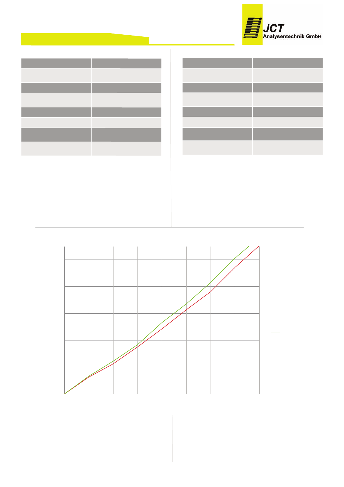
Pressure characteristics4.1.
(with new filter)
BA_DE_JES301E1_2.0 –––––––––––––––––––––––––– [ 10 ] ––––––––––––––––––––––––––
Manual JES-301E1
*1Befestigungsmaterial wird mitgeliefert
Technische Änderungen vorbehalten
Druckverlauf4.1.
(bei neuem Filter)
Elektrik
Anschlussspannung
115-230 VAC 50/60 Hz
Leistungsaufnahme
pro Heizelement
ca. 80 W
Heizelement
PTC selbstlimitierend
Einschaltstrom
pro Heizelement
ca. 2 A
Absicherung
Extern, bauseits
Einschaltdauer
100 %
Kabeleingang Versorgung
M - Verschraubung 20 x 1,5
(schwarz)
Elektrischer Anschluss
Schraubklemmen
0,2...4 mm
2
Electrical
Power supply 115-230 VAC 50/60 Hz
Power consumption per heating element
approx. 80 W
Heater PTC self limited
Inrush current per heating
element
ca. 2 A
Fusing External, on site
On-time 100 %
Cable entry supply M - panduit 20 x 1,5 (black)
Electrical connection
Screw type terminal
0,2...4 mm
2
0,00
20,00
40,00
60,00
80,00
100,00
0
400
600
800
1000
1200
1400
1600
1800
delta p [mbar]
Flow [l/h]
filter & air @ 20°C
2µ Filter
0,2µ Filter
Page 11
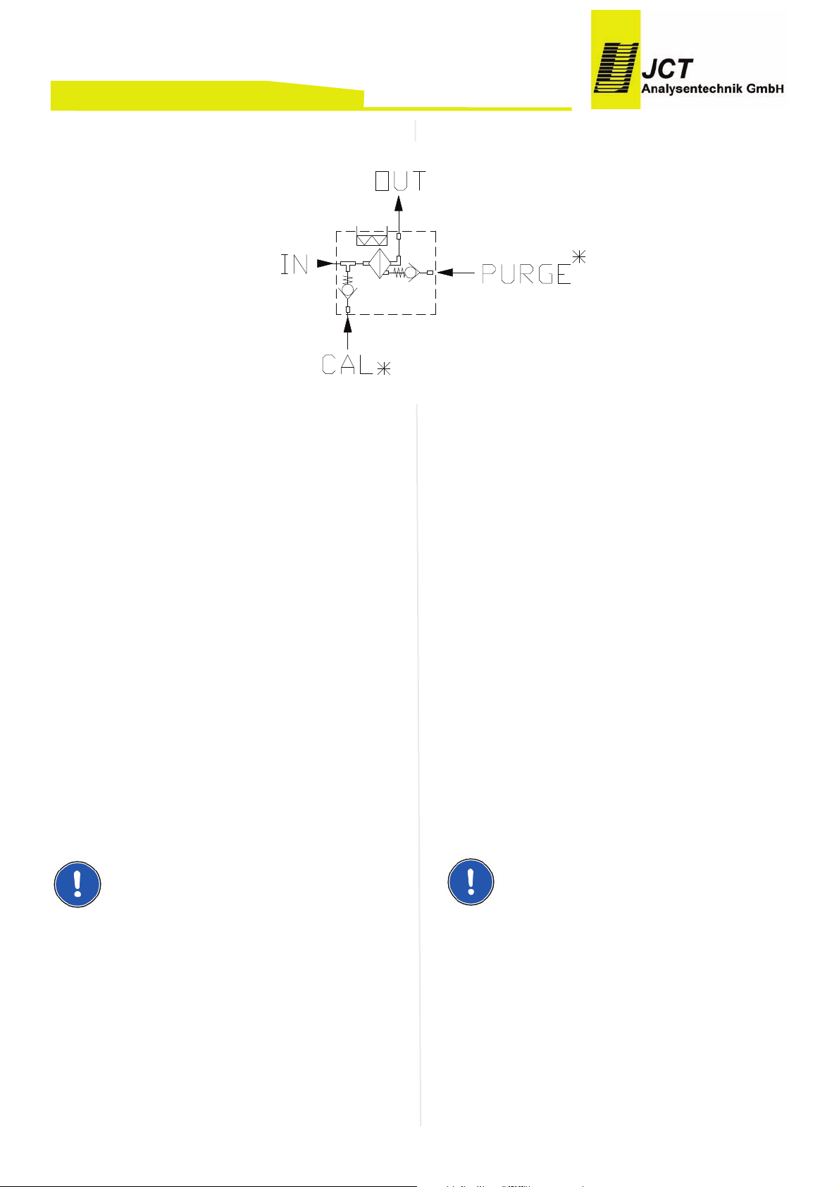
Flow charts4.2.
*...not in all models included
Installation, unpacking5.
Check instrument for any damage caused by shipping.
I
f any damage is established, contact the carrier and dis-
tributor immediately.
Check instrument and any other parts against order.
Installation instructions6.
Disconnect mains before working on electrical part•
of equipment.
The equipment has to be connected and grounded•
according to the local rules and regulations.
The probe mounting has to be done always with a•
minimum inclination of 5° towards the sampling pipe.
This is necessary to prevent a possible flow back
from condensate into the probe.
Mounting6.1.
Mount probe with gasket on the process flange.•
NOTE
The flange temperature must not exceed 200°c. Otherwise a change of construction is necessery, eg. use of a
thermal spacer.
Take care for correct mounting angel according tech-•
nical specification.
Mount 1/8“ NPT male connector at sample gas out-•
let.
Attach heated sample line on probe enclosure with•
moveable PG42 cable conduit or mounting clamp.
Connect the line with the connector fitting gas-tight.
BA_DE_JES301E1_2.0 –––––––––––––––––––––––––– [ 11 ] ––––––––––––––––––––––––––
Manual JES-301E1
Gasfluss Diagramm4.2.
*...nicht bei allen Modellen vorhanden
Installation, Sichtkontrolle5.
Nach dem Auspacken ist das Gerät auf allfällige Transportschäden
zu untersuchen. Wurde ein Schaden festgestellt, sind unverzüglich die verantwortliche Spedition
und der Händler zu benachrichtigen.
Es ist zu überprüfen, ob die Gerätelieferung Ihrer Bestellung entspricht.
Installationsvorschriften6.
Bei Arbeiten am elektrischen Teil des Gerätes ist es•
vom Netz zu trennen.
D
as Gerät muss entsprechend den örtlich geltenden•
Vorschriften angeschlossen und geerdet werden.
Die Sonde muss immer mit einer Mindestneigung•
von 5° gegen das Entnahmerohr hin montiert werden. Dies ist erforderlich um einen allfällig möglichen
Rückfluss des Kondensates in die Entnahmesonde
zu verhindern.
Montage6.1.
Sonde mit Dichtung am Prozessflansch montieren.•
HINWEIS
Die Flanschtemperatur darf 200°C nicht überschreiten,
sonst ist eine konstruktive Änderung, z.B: Einsatz eines
Thermal Spacers, notwendig.
Einbauwinkel gemäß technischer Spezifikation be-•
achten.
1/8“ NPT Einschrauber am Messgas Ausgang mon-•
tieren.
Beheizte Messgasleitung mit verschiebbarer PG42•
oder Montageschelle am Gehäuse befestigen und
mit dem Einschrauber gasdicht verbinden.
Page 12
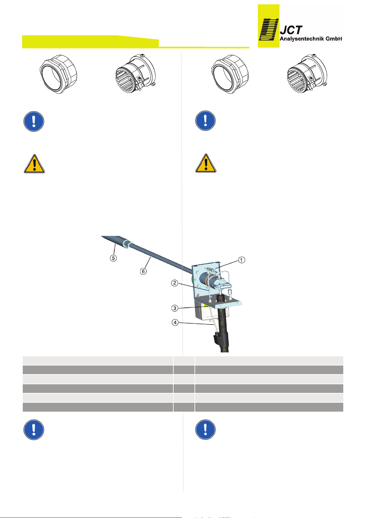
PG 42 Mounting clamp
NOTE
The heated sample line must be strain relieved and must
not be hung on the fitting.
CAUTION!
Never use grease for mounting sample pipe!
Calibration port (option)6.2.
Connect tube for calibration gas gas-tight with cali-•
bration port.
NOTE
For heated hoses with two inner cores on front side:
Open connections at check valve and bulkhead con-
nector, remove calibration gas pipe and connect calibration tube directly on check valve with the bulkhead
ferrules
BA_DE_JES301E1_2.0 –––––––––––––––––––––––––– [ 12 ] ––––––––––––––––––––––––––
Manual JES-301E1
PG 42 Montageschelle
HINWEIS
Die beheizte Messgasleitung muss zugentlastet und darf
nicht am Fitting abgehängt werden.
ACHTUNG!
Niemals Fett bei der Montage des Entnahmerohrs verwenden!.
Kalibriergasanschluss (Option)6.2.
Schlauch für Kalibriergas mit Kalibriergasanschluss•
gasdicht verbinden.
HINWEIS
Bei Einsatz von Heizleitungen mit zwei frontseitig herausgeführten Innenseelen:
Verbindungen bei Prüfventil und Schottverschraubung
lösen, Kalibriergasrohr entfernen und Kalibriergasleitung
mit Front und Backferrul der Schottverschraubung direkt
am Rückschlagventil montieren.
Prüfventil 1 Check valve
Kalibriergasrohr 2 Calibration gas pipe
Schottverschraubung 3 Buckhead connection
Kalibriergasleitung 4 Calibration tube
Vorfilter 5 Prefilter
Entnahmerohr 6 Sampling pipe
Page 13
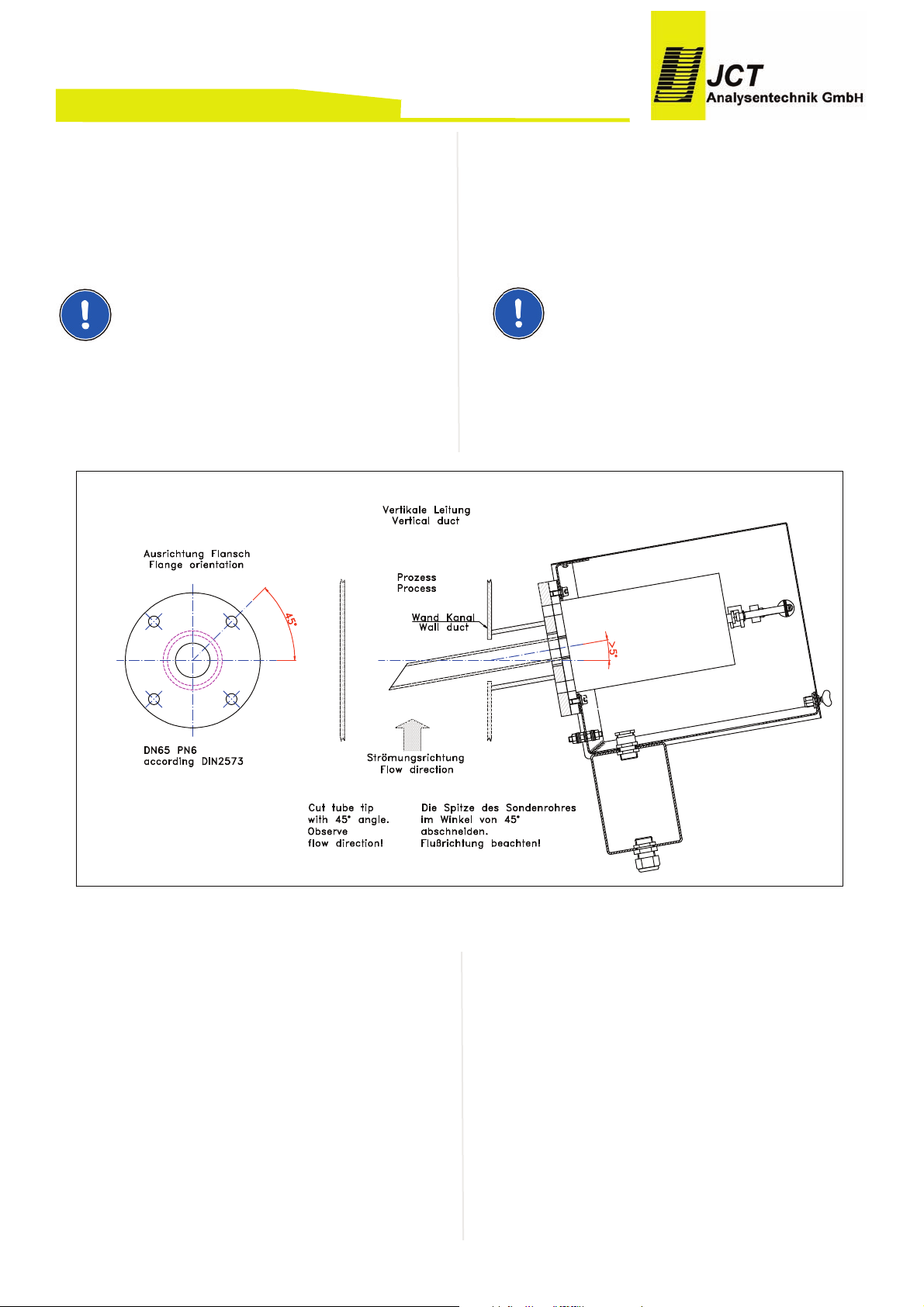
Back purge port (option)6.3.
Connect tube with inert gas coming from the optional
valve box JES-301KE1 gas-tight with back purge port.
NOTE
For back purging follow the documentation for the valve
box JES-301KE1.
Vertical duct installation6.4.
BA_DE_JES301E1_2.0 –––––––––––––––––––––––––– [ 13 ] ––––––––––––––––––––––––––
Manual JES-301E1
Anschluss für Rückspülung (Option)6.3.
Schlauch mit inertem Gas von der optionalen Ventilbox
JES-301KE1 mit dem Anschluss für Rückspülung gasdicht verbinden.
HINWEIS
Für Rückspülung ist die Dokumentation der Ventilbox
JES-301KE1 zu beachten
Montage an vertikalem Kamin6.4.
Page 14
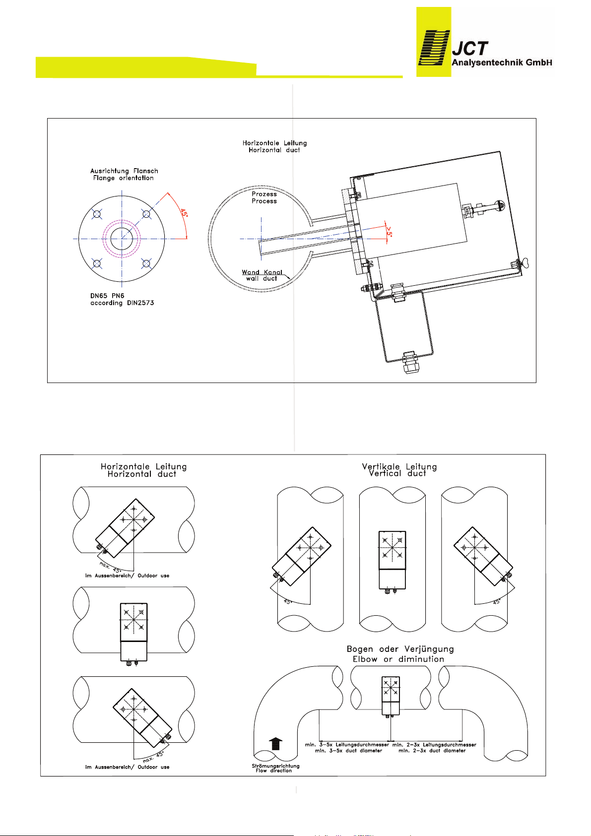
Horizontal duct installation6.5.
Mounting positions6.6.
BA_DE_JES301E1_2.0 –––––––––––––––––––––––––– [ 14 ] ––––––––––––––––––––––––––
Manual JES-301E1
Montage an horizontalem Kamin6.5.
Montage Positionen6.6.
Page 15
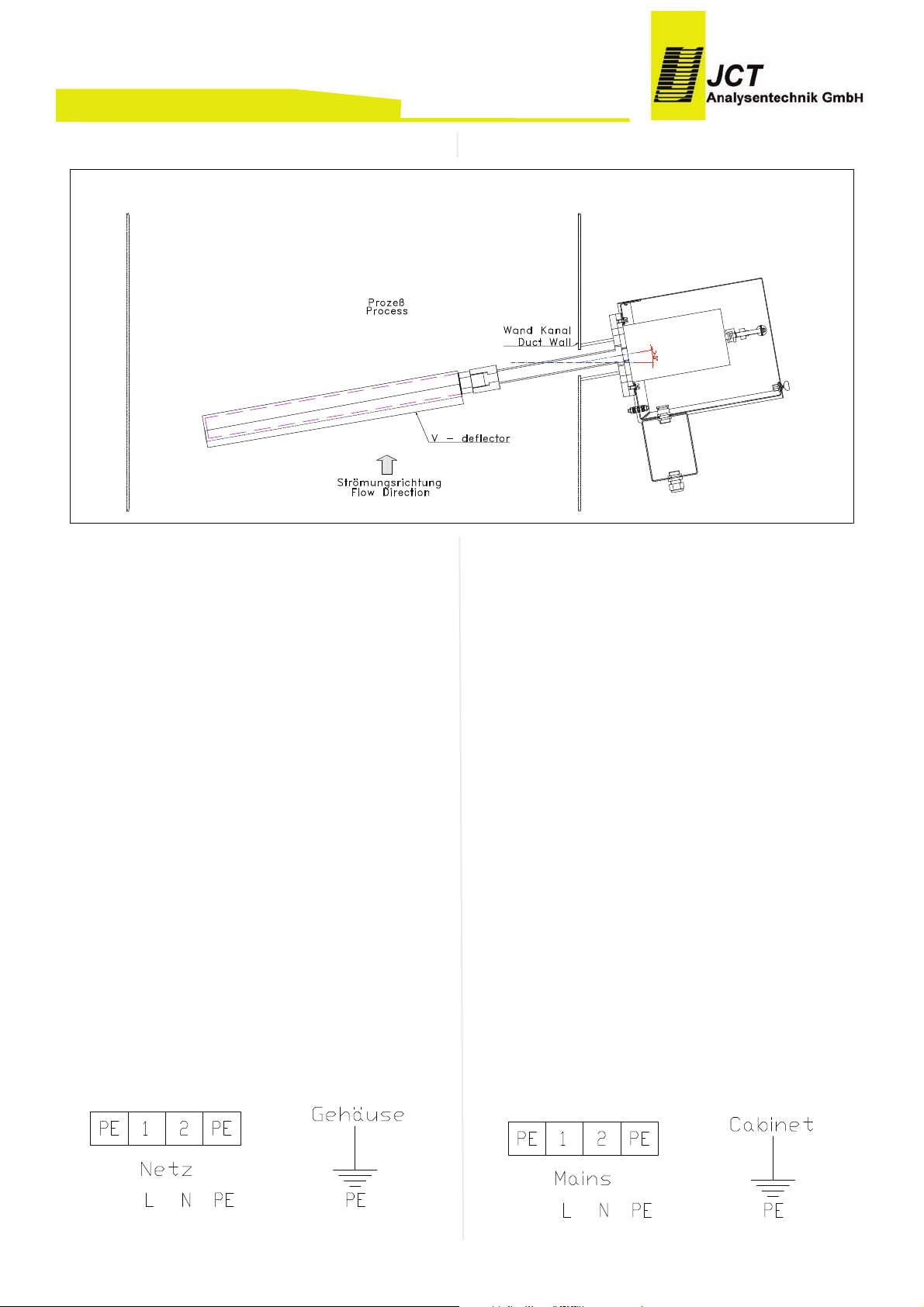
Mounting of In-situ pre filter6.7.
Electrical connections6.8.
Check local voltage, frequency and power consump-•
tion against type plate.
Connect a 2-pole switch in mains supply; the sample•
probe is not equipped with a switch.
The equipment has to be connected and additionally•
grounded with a wire of sufficient diameter on the
ground connection of the housing according to the
local rules and regulations.
The conductor isolation must reach to the terminal.•
The conductor itself must not be damaged (nicked)
when removing the insulation.
Ensure that the maximum permissible conductor•
temperatures are not exceeded by suitable selection
of cables and means of running them. The rated
cross-section of the wire strands from the cable
must be at lest 0,75mm² and may not exceed
2,5mm².
The operator must provide suitable stress relief.•
Fusing has to be done on site according local rules•
and regulations.
BA_DE_JES301E1_2.0 –––––––––––––––––––––––––– [ 15 ] ––––––––––––––––––––––––––
Manual JES-301E1
Montage In-situ Vorfilter6.7.
Elektrischer
Anschluss6.8.
Örtliche Netzspannung, Netzfrequenz und Leis-•
tungsaufnahme mit den Angaben am Typenschild
vergleichen.
In der Energieversorgungszuführung ist ein 2-poli-•
ger Netzschalter einzubauen, die Sonde besitzt keinen eigenen Netzschalter.
Das Gerät muss entsprechend den örtlich geltenden•
Vorschriften angeschlossen, sowie zusätzlich über
den Erdungsanschluss am Gehäuse, mit einem Leiter ausreichenden Querschnitts geerdet werden.
Die Leiterisolation muss bis an die Klemme heran-•
reichen. Beim Abisolieren darf der Leiter selbst nicht
beschädigt (gekerbt) werden.
Durch Auswahl einer geeigneten Anschlussleitung•
ist sicherzustellen dass die max. zulässigen Leitertemperaturen nicht überschritten werden. Der Bemessungsquerschnitt der Leitungsadern des Kabels
muss mindestens 0,75mm² betragen und darf
2,5mm² nicht überschreiten.
Der Betreiber muss eine entsprechende Zugentlas-•
tung der Kabel gewährleisten.
Eine Absicherung die den örtlich geltenden Vor-•
schriften entspricht ist bauseits vorzusehen.
Page 16
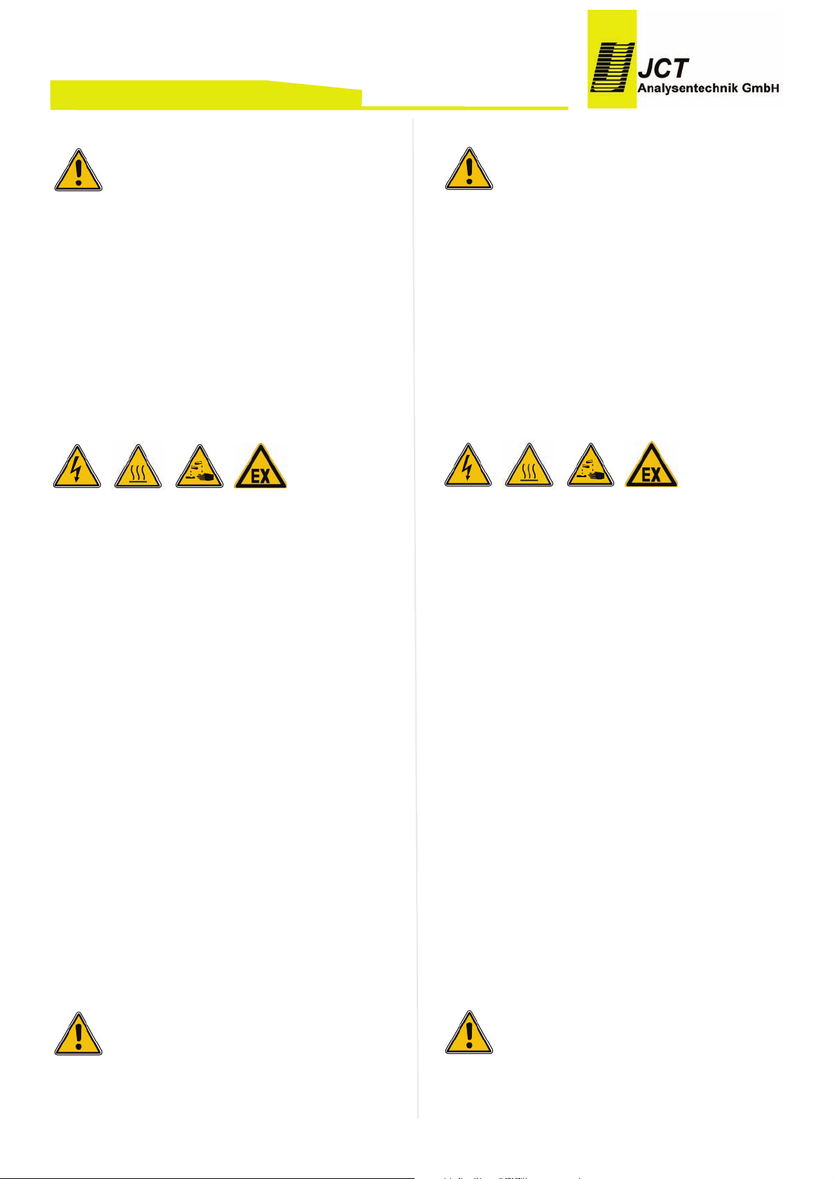
Terminal strip6.9.
CAUTION
This unit is operated with mains power. During operation
some parts of the unit are energised with dangerous voltage!
During operation the housing of the probe can get very
hot. Removing the probe housing will expose heated
parts. Disconnect power before repair or maintenance
and ensure that the internal temperature has dropped to
a safe level before working on it. Always wear heat resistant gloves. There is burn hazard if necessary precautionary steps are not taken.
If these warning notices are ignored possible serious injuries and/or damages may be caused.
Only qualified staff who has been trained according to
this manual should operate and maintain this instrument.
For certain and safe operation the instrument needs to
be transported carefully, be part of a well planned application, installed correctly as well as operated and maintained according to these instructions.
Requirements for qualifications of staff:
Qualified staff in the sense of this manual and/or the
warning references are persons, who are familiar with
assembly, mounting, start-up and operating of this product and have sufficient qualification for their tasks.
Start up7.
1. Check of the proper installation
2.
Review the equipment for damage.
3. Check for leaks.
4. Make sure the unit and connecting room are
clean and no foreign substances are inside.
5. Check all screws, nuts, terminals and cable en
tries for a tight fit.
CAUTION!
Before switching on sample probe ensure that the operating voltage of the unit and the line voltage are identical.
BA_DE_JES301E1_2.0 –––––––––––––––––––––––––– [ 16 ] ––––––––––––––––––––––––––
Manual JES-301E1
Klemmleiste6.9.
ACHTUNG
D
ieses Gerät wird mit Netzspannung betrieben. Beim
Betrieb dieses Gerätes stehen zwangsläufig bestimmte
Teile dieses Gerätes unter gefährlicher Spannung!
Im Betrieb kann das Gehäuse der Sonde sehr heiß werden. Durch Abnahme des Gehäuses werden heiße Teile
zugänglich. Bei jeglichen Arbeiten an der Sonde ist das
Gerät abzuschalten, die Abkühlung abzuwarten und in
jedem Fall sind Schutzhandschuhe zu tragen. Beim Berühren der internen Teile der Sonde besteht Verbrennungsgefahr.
Bei Nichtbeachtung der Warnhinweise können schwere
Personenschäden und/oder Sachschäden auftreten.
Nur entsprechend qualifiziertes und geschultes Personal
darf an diesem Gerät oder in dessen Nähe arbeiten.
Dieses Personal muss mit allen Warnungen und Instandhaltungs - Maßnahmen gemäß dieser Betriebs-anleitung vertraut sein.
Der einwandfreie und sichere Betrieb dieses Gerätes
setzt sachgemäßen Transport, fachgerechte Lagerung,
Aufstellung und Montage sowie sorgfältige Bedienung
und Instandhaltung voraus.
Anforderungen an die Qualifikation des Personals:
Qualifiziertes Personal im Sinne dieser Betriebsanlei-
tung bzw. der Warnhinweise sind Personen, die mit Aufstellung, Montage, Inbetriebsetzung und Betrieb dieses
Produktes vertraut sind und die über eine ihrer Tätigkeit
entsprechenden Qualifikation verfügen.
Inbetriebnahme7.
1. Kontrolle der vorschriftsgemäßen Installation
2.
Überprüfung des Gerätes auf Beschädigung
3. Dichtheitsprüfung durchführen.
4. Sicherstellen, dass Gerät und Anschlussraum
sauber sind und sich keine Fremdkörper darin
befinden.
5. Kontrolle aller Schrauben, Muttern Klemmen
und Leitungseinführungen auf festen Sitz.
ACHTUNG!
Vor dem Einschalten ist sicherzustellen, dass die am
Gerät eingestellte Betriebsspannung und die Netzspannung übereinstimmen.
Page 17
CAUTION!
Junction box has to be closed tight before start up!
6. Switch on the power supply of the sample probe.
After a lead time of approx. 180 min the operation temperature will be reached.
CAUTION!
Non-compliance with the control steps can lead to serious hazards or property damage and personal injury!
Feeding of calibration gas:
1. Feed calibration gas with minor over pressure (ap-
prox. 2l/min more than sample gas flow) into calibration
port.
2. Excess calibration gas flows off into the process.
NOTE
For back purging follow the documentation for the valve
box JES-301KE1.
Maintenance and service8.
NOTE
If
an item is returned to JCT Analysentechnik, for maintenance or repair reasons, it will only be accepted with
accompanied “Return Authorisation” and “Decontamination Statement”, fully completed and signed. This is to
ensure the security of JCT staff. The forms including a
valid “Return Authorisation Number” (RAN) are available
on request at the JCT service department or for download on the JCT website.
Replacement of filter element8.1.
Filter elements are consumables and have to be replaced regularly, at least once a year. For cleaning or replacing following steps should be done:
BA_DE_JES301E1_2.0 –––––––––––––––––––––––––– [ 17 ] ––––––––––––––––––––––––––
Manual JES-301E1
ACHTUNG!
Die Anschlussdose muss vor Inbetriebnahme dicht verschlossen sein!
6. Energieversorgung der Sonde einschalten.
Nach einer Vorlaufzeit von ca. 180 min wird die
Betriebstemperatur erreicht.
ACHTUNG!
Bei nicht Einhaltung der Kontrollschritte kann es zu
ernsthaften Gefährdungen oder zu Sach- und Personenschäden kommen!
Aufgabe von Kalibriergas:
1. Kalibriergas mit leichtem Überdruck (ca. 2l/min über
Druck des Messgasstroms) in Kalibriergasanschluss
einströmen lassen.
2. Abströmen des überschüssigen Kalibriergases erfolgt
in den Prozess.
HINWEIS
Für Rückspülung ist die Dokumentation der Ventilbox
JES-301KE1 zu beachten.
Wartung und Service8.
HINWEIS
Ist
es zu Wartungs- oder Reparaturzwecken notwendig,
das Gerät an JCT Analysentechnik zu schicken, sind die
„Return Authorisation“ und die „Erklärung zur gesundheitlichen Unbedenklichkeit“ vollständig ausgefüllt und
unterzeichnet beizulegen. Andernfalls kann das Gerät
zum Schutz der JCT Mitarbeiter nicht übernommen werden. Die Formulare sind mit einer gültigen Return Authorisation Number (RAN) auf Anfrage bei der
Serviceabteilung von JCT erhältlich und stehen auf der
JCT Website zum Download bereit.
Ersetzen des Filterelementes8.1.
Filterelemente sind Verbrauchsteile und sind abhängig
von den Einsatzbedingungen regelmäßig, mind. 1mal
pro Jahr zu warten. Für den Ersatz der Filterelemente
sind folgende Schritte vorzunehmen:
Page 18
NOTE
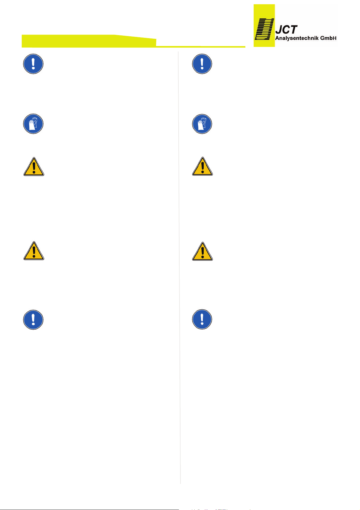
The ceramic filter elements are very fragile by their nature. Handle those elements with care and avoid dropping them.
Burn hazard!
Use heat resistant gloves.
CAUTION!
The housing of the probe may get very hot!
Take care, in case of process over pressure, explosive
and/or toxic gas emanation is possible.
To avoid accidents take care for necessary safety pre-
cautions in case of service and maintenance.
CAUTION!
Dropping parts can lead to formation of sparks!
When carrying out any work on the system the earth
connection must not be disconnected!
NOTE
Do not use earthing cable to hold weight of housing
cover.
Switch off the power supply and wait for cooling•
down of the probe.
Remove the weather protection housing.•
Turn away the handle (pos. 21) for pulling out the•
filter element. Swing the pivoting lever sideways and
pull out the support tube with the filter element.
Loosen tighten piston (pos. 6) from the support tube•
(pos. 9). Pull out filter element and gaskets.
Replace filter element (pos. 8) and/or gaskets•
(pos.7). clean groove on tighting piston of filter retainer (pos. 10) and remove O-rings (pos. 11 and 12)
with a non-metallic tool (wood or plastic wedge).
Apply a thin wetting of PTFE paste on O-rings and•
pull them on.
Remount gaskets (pos. 7) and filter element (pos.•
8).
BA_DE_JES301E1_2.0 –––––––––––––––––––––––––– [ 18 ] ––––––––––––––––––––––––––
Manual JES-301E1
HINWEIS
Die Keramikfilterelemente sind von ihrer Beschaffenheit
sehr zerbrechlich. Daher die Elemente vorsichtig handhaben und nicht fallen lassen.
Verbrennungsgefahr!
Hitzebeständige Handschuhe benutzen.
ACHTUNG!
Das Gehäuse der Sonde kann sehr heiß sein!
Bei Prozessüberdruck können explosive und/oder toxi-
sche Gase austreten.
Entsprechende Maßnahmen sind bei Wartung und Ser-
vice sowie Ersetzen oder Reinigen des Filterelementes
zu treffen.
ACHTUNG!
Durch Fallenlassen von Teilen kann es möglicherweise
zu Funkenbildung kommen!
Bei jeglichen Arbeiten am System darf die Schutzleiterverbindung am Gerät nicht getrennt werden!
HINWEIS
Gehäusedeckel nicht am Erdungsband abhängen.
Elektrische Zuleitung abschalten und warten bis die•
Sonde abgekühlt ist.
Wetterschutzhaube abnehmen.•
Durch Drehen des Griffs (Pos. 21) das Filterelement•
herausziehen. Schwenkarm zur Seite klappen und
Filterkolben herausziehen.
Filterelementverschraubung (Pos. 6) vom Träger-•
element (Pos. 9) lösen. Filterelement und Flachdichtungen herausnehmen.
Filter (Pos. 8) und/oder Flachdichtungen (Pos. 7) er-•
setzen. Nut am Dichtkolben des Filterhalter Trägerelements (Pos. 10) reinigen und die zwei
O-Ringemit einem nicht metallischen Werkzeug
(Holz- oder Kunststoffkeil) entfernen (Pos. 11 und
12).
Neue O-Ringe dünn mit PTFE-Paste benetzen und-•
aufziehen. Flachdichtungen (Pos. 7) und Filter (Pos.
Page 19

Screw on the filter element-screw (pos. 6).•
Clean the sealing surfaces in sample probe.•
Mount all other parts in vice versa sequence.•
Turn on heating.•
Demounting9.
Disconnect units supply at site. •
T
ake heated hose regarding its manual out of serv-•
ice.
Disconnect fitting from sample probe and loosen•
moveable PG42 from cabinet and remove heated
sample gas hose.
Ensure that sample probe can be removed from•
process without endangerment.
Remove probe from process flange.•
Disconnect cabinet grounding.•
Store and dispose with expertise.•
BA_DE_JES301E1_2.0 –––––––––––––––––––––––––– [ 19 ] ––––––––––––––––––––––––––
Manual JES-301E1
8) montieren.
Filterelementverschraubung festziehen (Pos. 6).•
Dichtungsflächen in der Sonde reinigen.•
Anschließend
erfolgt Montage in umgekehrter Rei-•
henfolge.
Beheizung einschalten.•
Demontage9.
Gerät anlagenseitig spannungsfrei machen.•
B
eheizte Messgasleitung gemäß dessen Bedie-•
nungsanleitung außer Betrieb nehmen.
Fitting an der Sonde lösen, verschiebbare PG42•
vom Gehäuse lösen und beheizte Messgasleitung
entfernen.
Sicherstellen, dass Sonde ohne Gefährdung vom•
Prozess getrennt werden kann.
Sonde vom Prozessflansch abmontieren.•
Erdungsanschluss vom Gehäuse trennen.•
Fachgerechte Aufbewahrung bzw. Entsorgung•
Page 20
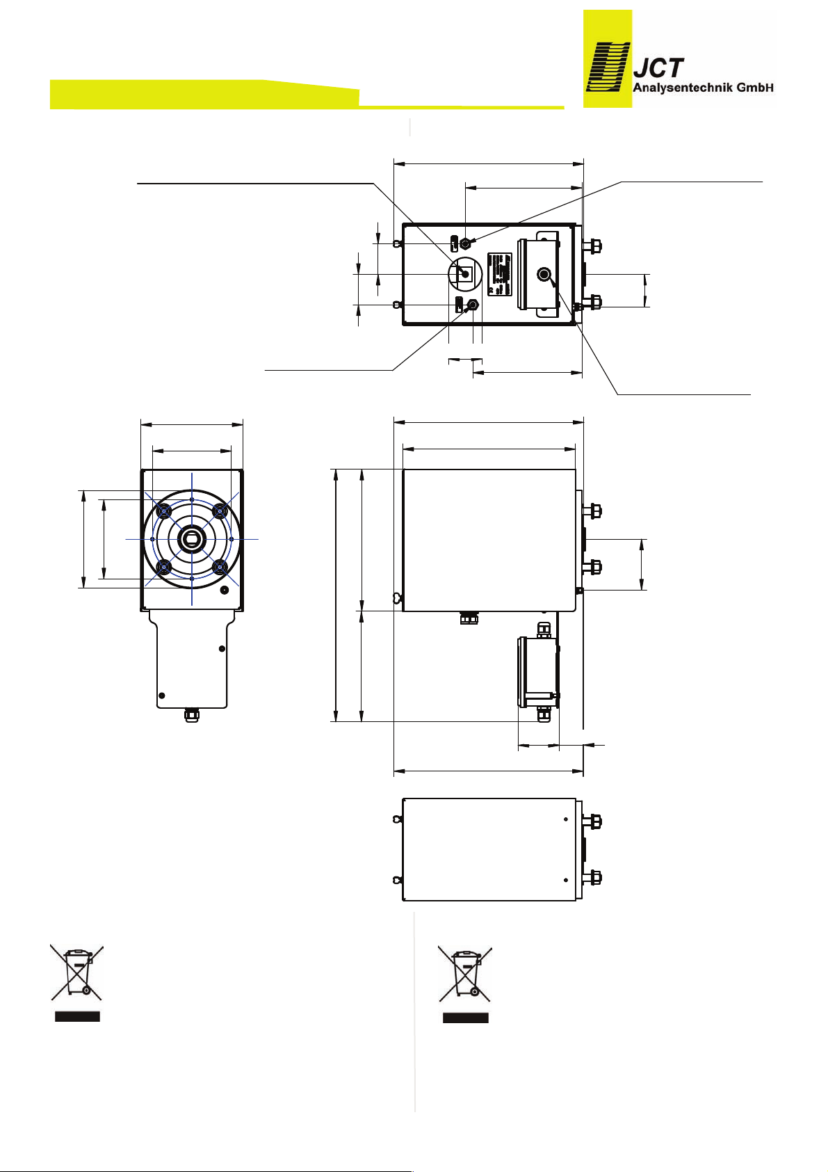
Dimensions10.
Recycling
The
unit contains elements which are suitable for recycling, and components which need special disposal. You
are therefore requested to make sure that the unit will
be recycled by the end of its service life.
BA_DE_JES301E1_2.0 –––––––––––––––––––––––––– [ 20 ] ––––––––––––––––––––––––––
Manual JES-301E1
Abmessungen10.
Recycling
Das
Gerät enthält Bauteile, die wiederverwertet werden
können, sowie Bauteile, die speziell entsorgt werden
müssen. Sorgen Sie deshalb dafür, dass das Gerät nach
der Verwendung der Wiederverwertung zugeführt wird.
/93.*1#,(
:(;*0
(.*/&(,:(&0
!" "# "$%
& '$
& (%"!!%"
)*'+* '$
,'+%!%"
.
..
"%!1%!%
!% 2
Page 21

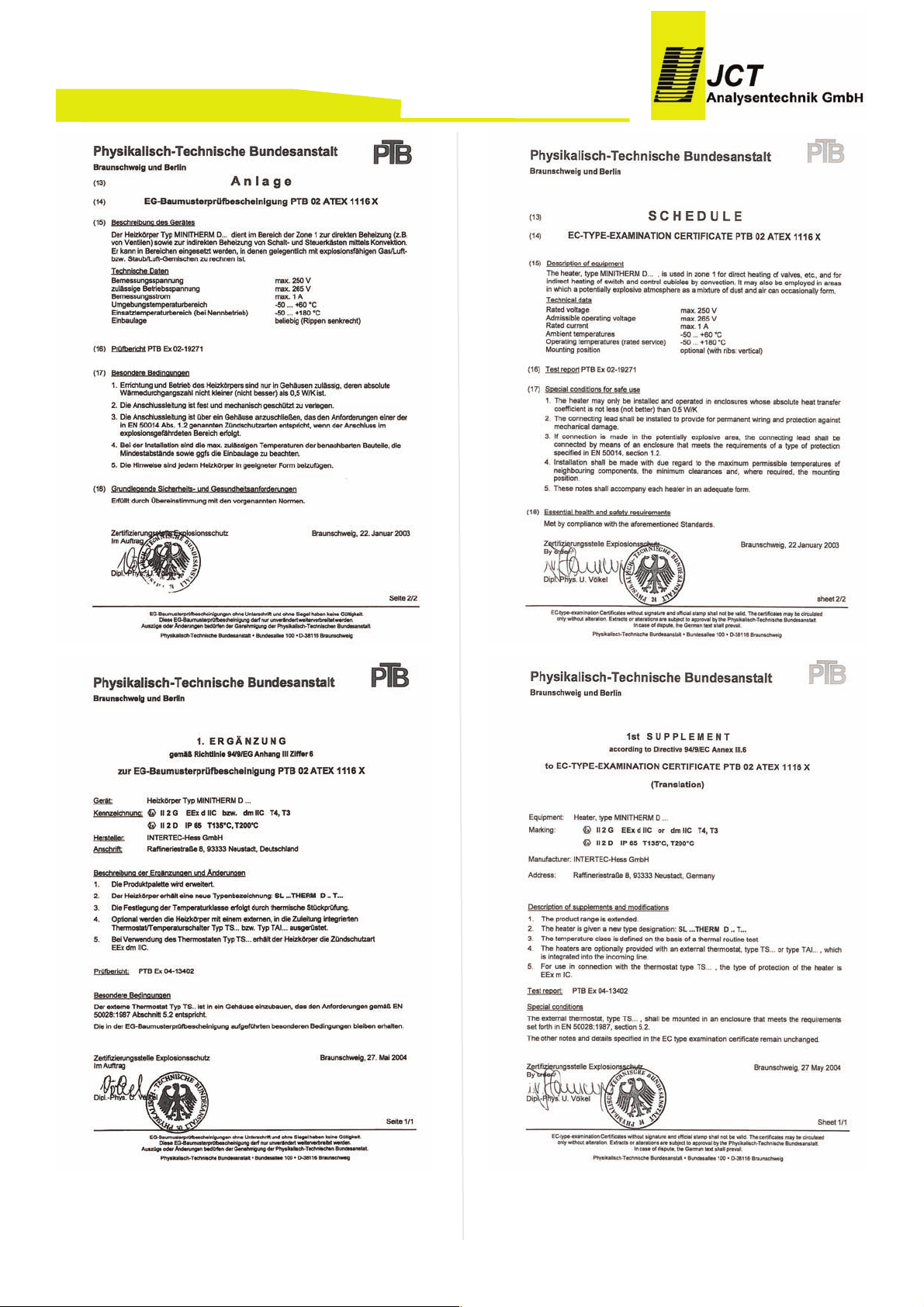
Certificates PTC heater11.
BA_DE_JES301E1_2.0 –––––––––––––––––––––––––– [ 21 ] ––––––––––––––––––––––––––
Manual JES-301E1
Zertifikate PTC Heizelement11.
Page 22
BA_DE_JES301E1_2.0 –––––––––––––––––––––––––– [ 22 ] ––––––––––––––––––––––––––
Manual JES-301E1
Page 23
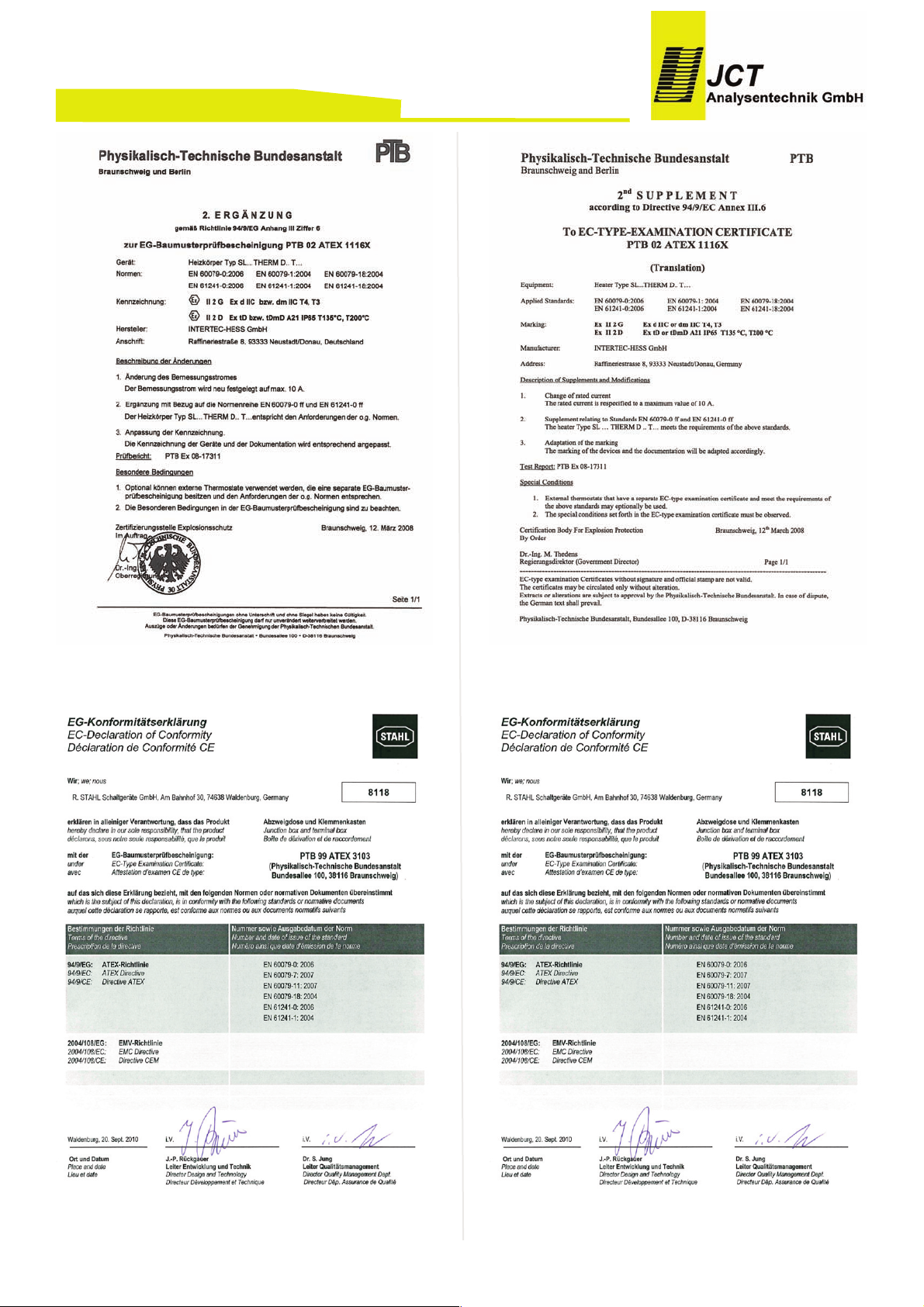
Certificates junction box12.
BA_DE_JES301E1_2.0 –––––––––––––––––––––––––– [ 23 ] ––––––––––––––––––––––––––
Manual JES-301E1
Zertifikate Klemmkasten12.
Page 24
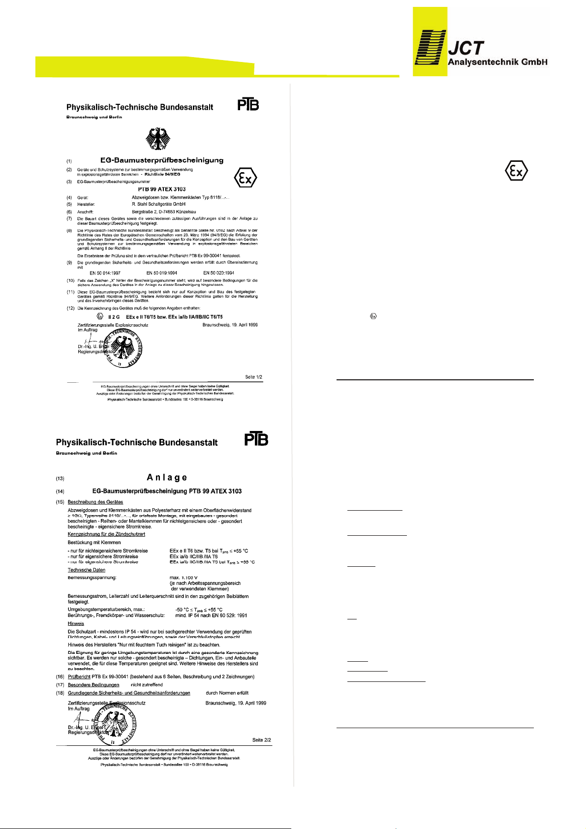
UNCERTIFIED TRANSLATION
Physikalisch-Technische Bundesanstalt
Braunschweig and Berlin
Page 1/2
EC-type-examination Certificates without signature and official stamp shall not be valid. The certificates may be circulated
only without alteration. Extracts or alterations are subject to approval by the Physikalisch-Technische Bundesanstalt.
In case of dispute, the German text shall prevail.
Physikalisch-Technische Bundesanstalt Bundesallee 100 D-38116 Braunschweig
(1) EC-TYPE-EXAMINATION CERTIFICATE
(2) Equipment and Protective Systems Intended for Use in
Potentially Explosive Atmospheres - Directive 94/9/EC
(3) EC Type Examination Certificate Number
PTB 99 ATEX 3103
(4) Equipment: Junction and Terminal Boxes Type 8118/...-...
(5)
Manufacturer
: R. Stahl Schaltgeräte GmbH
(6) Address: Bergstraße 2, D-74653 Künzelsau
(7) This equipment and any acceptable variation thereto are specified in the schedule to this
certificate.
(8) The Physikalisch-Technische Bundesanstalt, notified body No. 0102 in accordance with Article
9 of the Council Directive 94/9/EC of 23 March 1994, certifies that this equipment has been
found to comply with the Essential Health and Safety Requirements relating to the design and
construction of equipment and protective systems intended for use in potentially explosive
atmospheres, given in Annex II to the Directive.
The examination and test results are recorded in the confidential report PTB Ex 99-30041.
(9) Compliance with the Essential Health and Safety Requirements has been assured by
compliance with:
EN 50 014:1997 EN 50 019:1994 EN 50 020:1994
(10) If "X" is placed after the certificate number, it indicates that the equipment is subject to special
conditions for safe use specified in the schedule to this certificate.
(11) This EC-type-examination Certificate relates only to the design and construction of the
specified equipment in accordance with Directive 94/9/EC. Further requirements of this
Directive apply to the manufacture and supply of this equipment.
(12) The marking of the equipment shall include the following:
II 2 G EEx e II T6/T5 or EEx ia/ib IIA/IIB/IIC T6/T5
Zertifizierungsstelle Explosionsschutz Braunschweig, 19 April 1999
By order:
signed: U. Engel L.S.
Dr.-Ing. U. Engel
Regierungsdirektor
UNCERTIFIED TRANSLATION
Physikalisch-Technische Bundesanstalt
Braunschweig and Berlin
Page 2/2
EC-type-examination Certificates without signature and official stamp shall not be valid. The certificates may be circulated
only without alteration. Extracts or alterations are subject to approval by the Physikalisch-Technische Bundesanstalt.
In case of dispute, the German text shall prevail.
Physikalisch-Technische Bundesanstalt Bundesallee 100 D-38116 Braunschweig
(13) S C H E D U L E
(14)
EC-Type Examination Certificate PTB 99 ATEX 3103
(15) Description of the equipment
Junction and terminal boxes of polyester resin with a surface resistance ≥ 1 GΩ, Type series
8118/...-..., for fixed installation, with built-in - separately certified - line-up or hood-type
terminals for non-intrinsically safe or - separately certified - intrinsically safe circuits.
Marking of explosion protection
Fitting with terminals
- only for non-intrinsically safe circuits EEx e II T6 or T5 for T
amb
≤ + 55 °C
- only for intrinsically safe circuits EEx ia/ib IIC/IIB /IIA T6
- only for intrinsically safe circuits EEx ia/ib IIC/IIB /IIA T5 for T
amb
≤ +55 °C
Technical data
Rated voltage: max. 1100 V
(depending on the operating voltage range
of the terminals used)
Rated current, number of conductors and conductor cross section are determined in the
associated additional sheets.
Ambient temperature range, max.: -50 °C ≤ T ≤ +55 °C
Contact, foreign particles and water protection min. IP 54 to EN 60 529: 1991
Note
The degree of protection - at least IP 54 - is achieved only when the tested gaskets, cable
glands and stopping plugs are used properly.
Instruction of the manufacturer "Clean only with wet cloth" is to be followed.
The suitability for low ambient temperatures is visible by special marking. Only such separately
certified sealing gaskets and built-in and built-on components, which are suitable for these
temperatures, are used. Additional instructions of the manufacturer are to be followed.
(16) Test report PTB Ex 99-30041 (consisting of 6 pages, description and 2 drawings)
(17) Special requirements not applicable
(18) Essential health and safety requirements covered by standards
Zertifizierungsstelle Explosionsschutz Braunschweig, 19 April 1999
By order:
signed: U. Engel L.S.
Dr.-Ing. U. Engel
Regierungsdirektor
BA_DE_JES301E1_2.0 –––––––––––––––––––––––––– [ 24 ] ––––––––––––––––––––––––––
Manual JES-301E1
Page 25
BA_DE_JES301E1_2.0 –––––––––––––––––––––––––– [ 25 ] ––––––––––––––––––––––––––
Manual JES-301E1
Page 26
BA_DE_JES301E1_2.0 –––––––––––––––––––––––––– [ 26 ] ––––––––––––––––––––––––––
Manual JES-301E1
Page 27

BA_DE_JES301E1_2.0 –––––––––––––––––––––––––– [ 27 ] ––––––––––––––––––––––––––
Manual JES-301E1
Page 28

Werner Heisenberg - Str. 4 / A-2700 Wr. Neustadt / Tel +43 (0)2622 87 201 / Fax +43 (0)2622 87 2011
[email protected] / Firmenbuchgericht: Kreisgericht Wr. Neustadt FN 119682 d / UID - Nummer ATU 20559900
Manual JES-301E1
BA_DE_JES301E1_2.0 –––––––––––––––––––––––––– [ 28 ] ––––––––––––––––––––––––––
Manual JES-301E1
 Loading...