

Page 1
Global LCD Panel Exchange Center
SPECIFICATION
TFT-LCD MODULE
www.panelook.com
FOR
CJM16C0101
JILIN CAIJING DIGITAL TECHNOLOGY
PANELS Co., Ltd
1999/9/30
One step solution for LCD / PDP / OLED panel application: Datasheet, inventory and accessory!
www.panelook.com
Page 2
Global LCD Panel Exchange Center
CJM16C0101
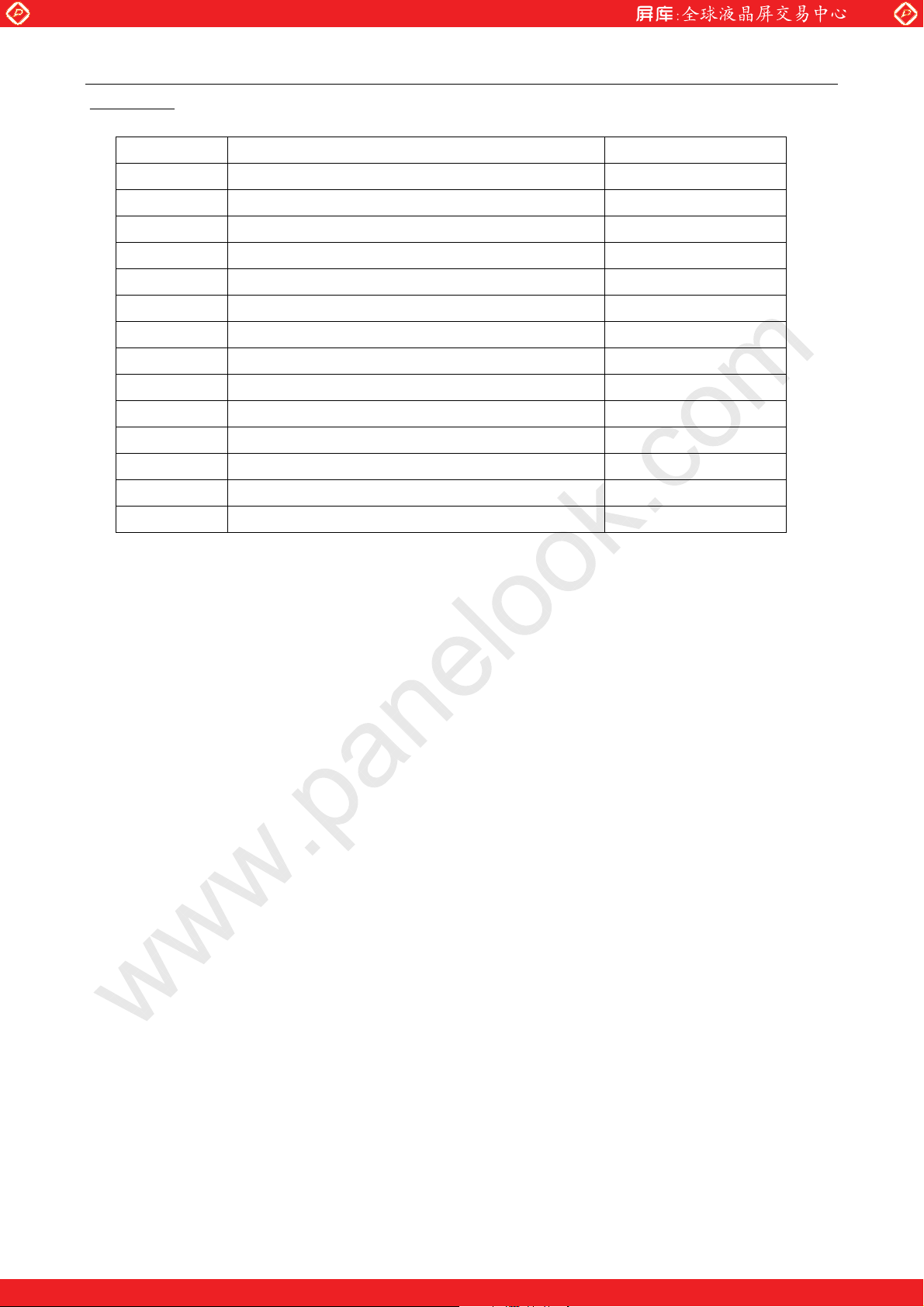
Contents
No. Item Page
1 Revision History 3
2 Mechanical Characteristics Data 4
3 Absolute Maximum Ratings 4
4 Optical Characteristics 5
5 Color Arrangement 8
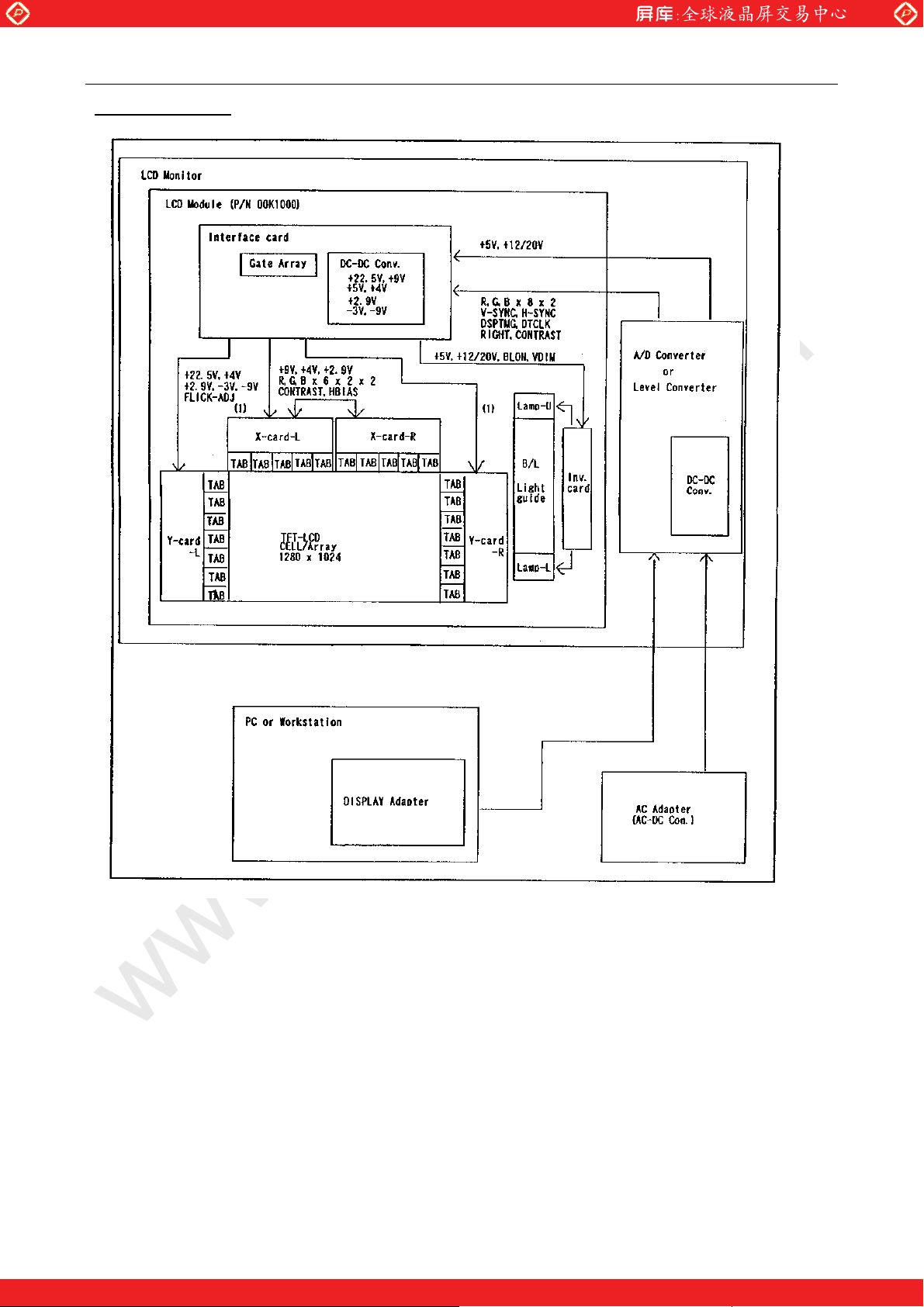
6 Block Diagram 9
7 Signal Interface 10
8 Color Code 12
9 Signal Specification 13
10 Interface Timing 14
11 Power Requirement 17
12 Power On/Off Sequence 18
13 Outline Dimension 19
www.panelook.com
14 Note 21
- - 2
One step solution for LCD / PDP / OLED panel application: Datasheet, inventory and accessory!
www.panelook.com
Page 3
Global LCD Panel Exchange Center
CJM16C0101
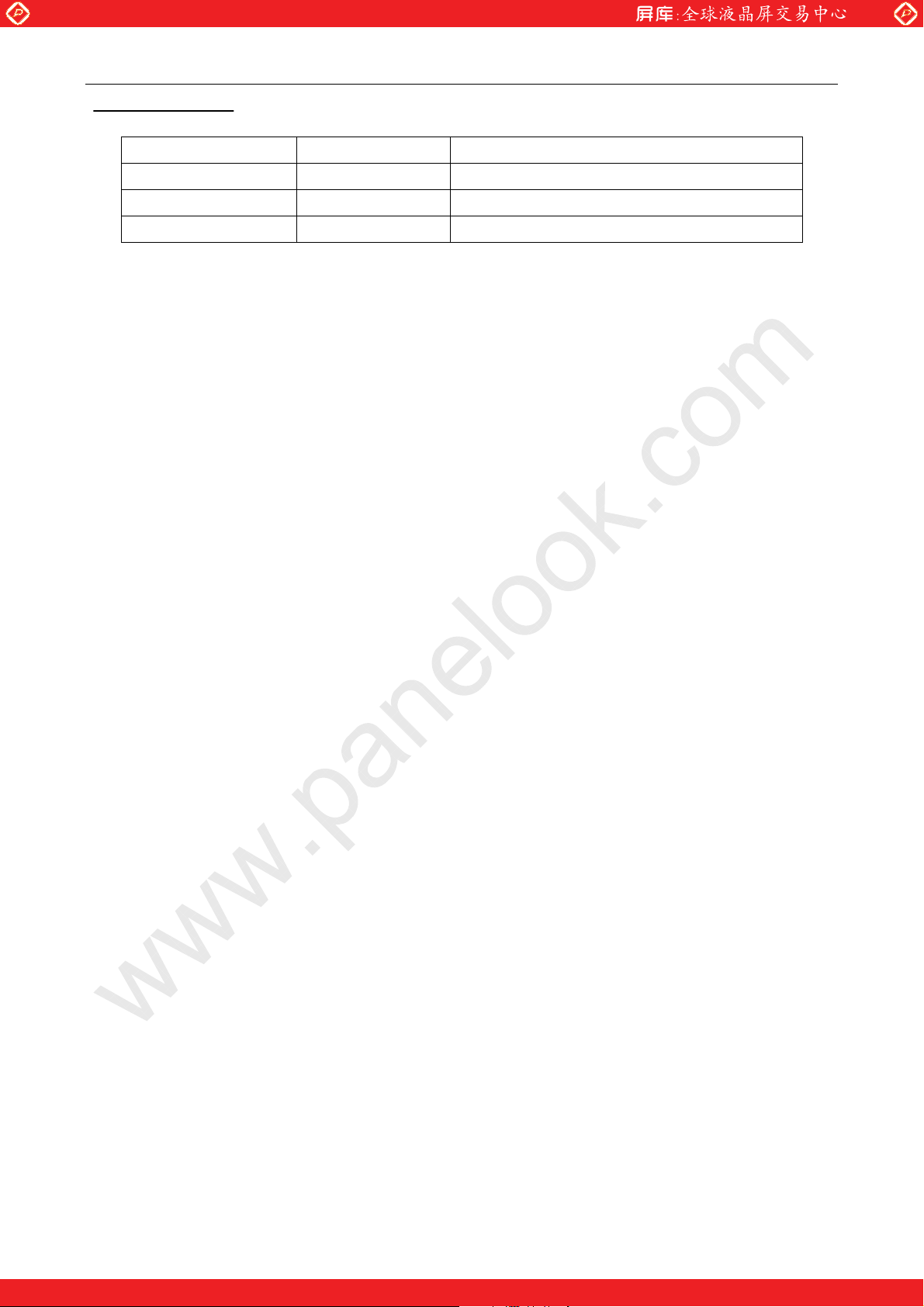
1.Revision History
Date of Revision Affected Pages Reasons of Revision
www.panelook.com
- - 3
One step solution for LCD / PDP / OLED panel application: Datasheet, inventory and accessory!
www.panelook.com
Page 4
Global LCD Panel Exchange Center
CJM16C0101
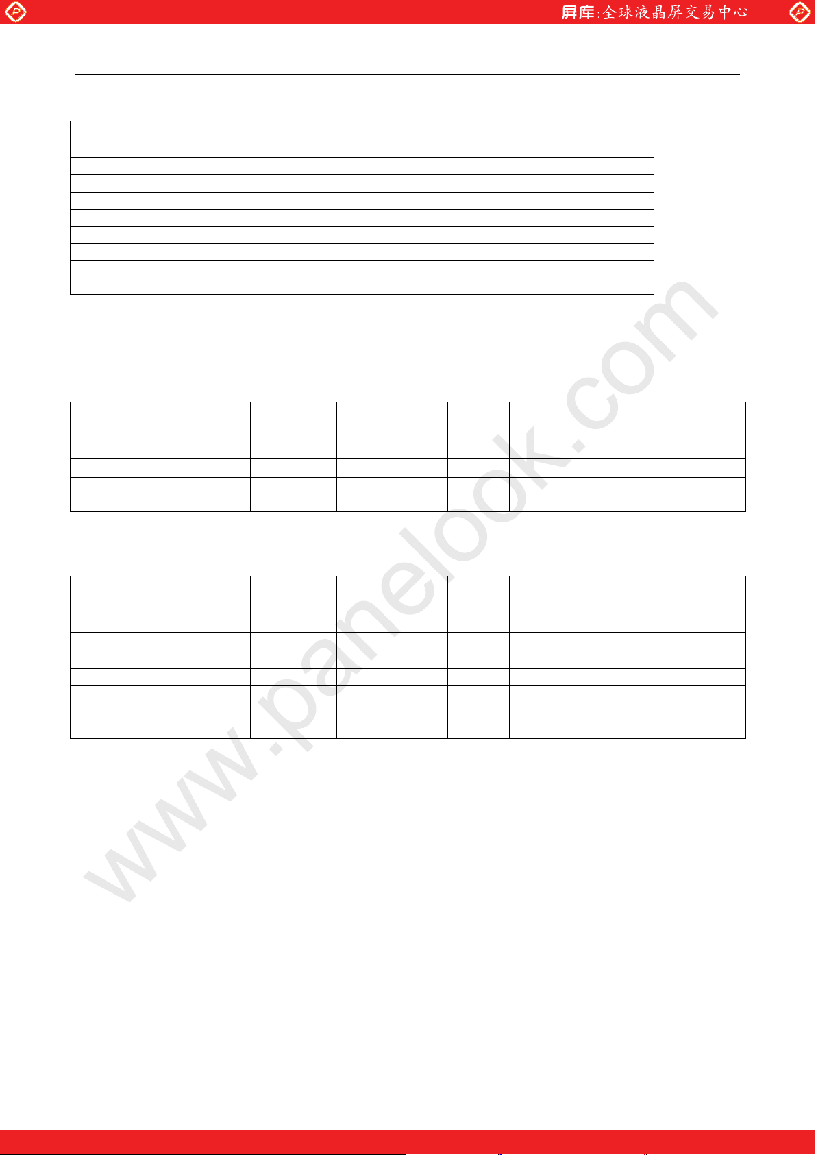
2.Mechanical Characteristics Data
Physical Size 400mm×333mm×40.7mm(Typ.)
Screen Diagonal
Active Area 318.7mm(H)×255.0mm(V)
Pixel Format 1280(×3)×1024
Pixel Pitch 0.249(per one triad)×0.249mm
Pixel Arrangement R,G,B in triad arrangement
Weight 3080 grams Max.
LCD Surface Treatment Antiglare and Hard coat 3H
Backlight
3.Absolute Maximum Ratings
Electrical Absolute Maximum Ratings
Rating Symbol Value Unit Conditions
Supply Voltage VDD
Supply Voltage VBL
Input Voltage VIN
Static Electricity
www.panelook.com
40.9cm(16.1ą)
Cold Cathode Fluorescent Lamp (CCFL)
with inverter
-0.3 +7.0
-0.3 +21.0
-0.3 +5.25
V
V
V
Operators should be grounded in
handling the TFT LCD Module
Environmental Absolute Maximum Ratings
Rating Symbol Value Unit Condition
Storage Temperature TST -20 to+60
Operation Temperature TOP 0 to+50
Operation Humidity 5 to 80 %RH
Vibration 1.5 G 10V/200Hz,X,Y,Z(Note1)
Trapezoidal Shock 35 G
Corrosive Gas
Note 1:At testing Vibration and Shock, the fixture in holding the Module to be tested have to be hard
and rigid enough so that the Module would not be twisted or bent by the fixture.
Not
Acceptable
ć
ć
At the glass surface
At the glass surface
Max wet bulb temp.29 ć No
condensation
20msec,fX,Y,Z(Note1)
- - 4
One step solution for LCD / PDP / OLED panel application: Datasheet, inventory and accessory!
www.panelook.com
Page 5
Global LCD Panel Exchange Center
CJM16C0101
4.Optical Characteristics
www.panelook.com
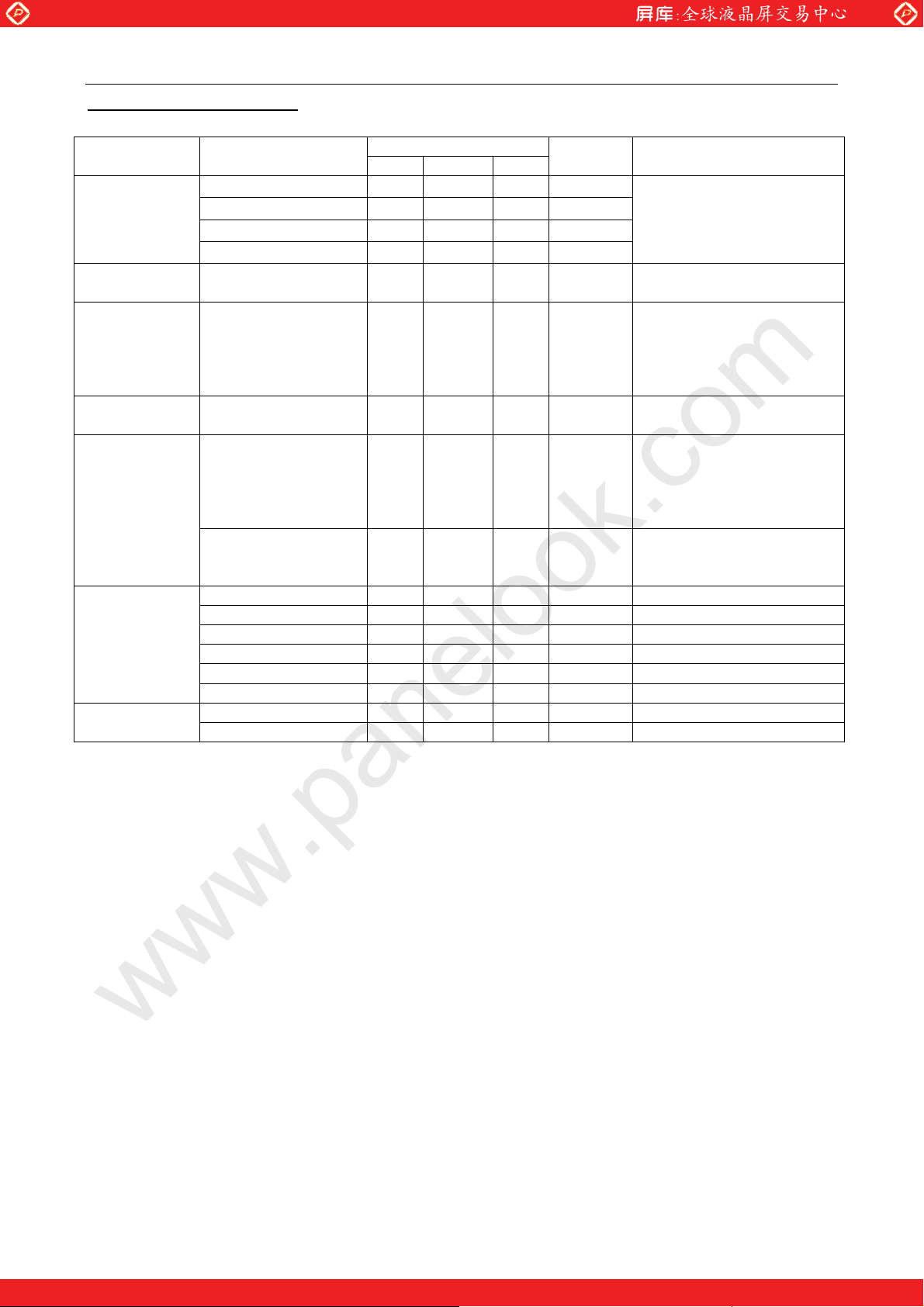
Item Conditions
h=0e,v=+20e
Viewing Angle
Contrast h=0,v=0 60 100
Response
Time
White
Luminance
Luminance
Uniformity
Chromaticity
White Balance
h=0e,v=-20e
h=±40e,v=0e
h=±20e,v=0e
Both On/Off.
From/To 10%
luminance To/From
90% luminance
level.
Gray Scale L=L255
h=0,v=0.
Adjacent Area 0.80
Screen Total 0.60
Red x 0.639 ±0.030
Red y 0.329 ±0.030
Green x 0.301 ±0.030
Green y 0.581 ±0.030
Blue x 0.137 ±0.030
Blue y 0.117 ±0.030
x 0.310 ±0.030
y 0.346 ±0.030
Specification
Min. Typ. Max.
5
20
10
45
30 50 msec
200 Cd/m
Unit Notes
2
In the unit of Contrast
Ratio K
In the unit of Contrast
Ratio K
Ambient Temperature
25 . At Center of LCD. ć
h=0,v=0
At Center of LCD
Ratio of (Ldark/Lbright)
over a circular area of
10mm diameter placed
any one of 81 points of the
screen.
Ratio of (Ldark/Lbright) for
any two of 81 measuring
points of the screen
- - 5
One step solution for LCD / PDP / OLED panel application: Datasheet, inventory and accessory!
www.panelook.com
Page 6
Global LCD Panel Exchange Center
CJM16C0101
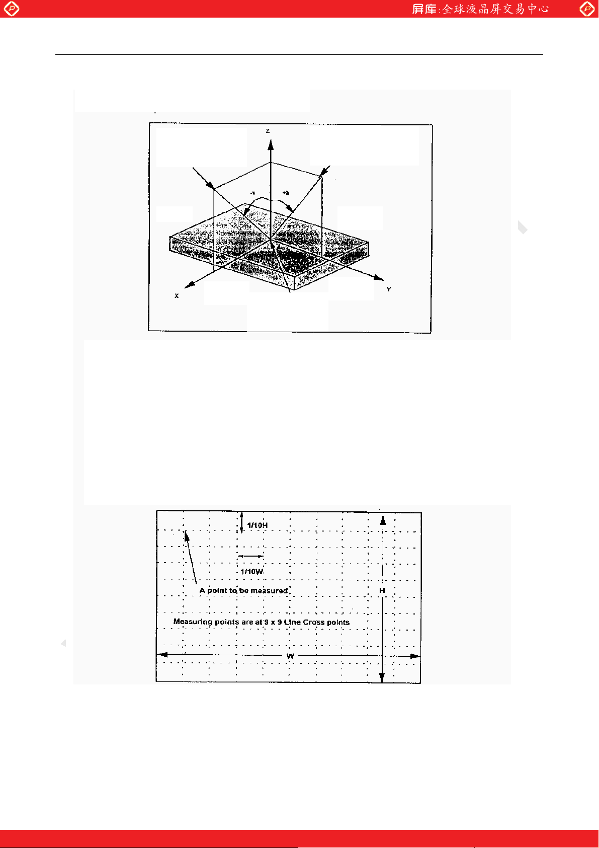
Notes for the Optical Characteristics:
Notes for the Optical Characteristics:
www.panelook.com
Viewing or Measuring
Direction
LEFT
LOWER
CENTER OF LCD
(X=0,Y=0,Z=0)
Viewing or Measuring
Direction
UPPER
RIGHT
gGray Scale Level is denoted by Lxx.(ex.L00 means all Pels are in the selected state)
(Uniformity Measurement)
g’Lbright’ represents the Luminance of the point that is brighter than the other point to be
compared.
g’Ldark’ represents the Luminance of the point that is darker than the other point to be
compared.
gMeasuring points are at the following.
- - 6
One step solution for LCD / PDP / OLED panel application: Datasheet, inventory and accessory!
www.panelook.com
Page 7
Global LCD Panel Exchange Center
CJM16C0101
gChromaticity and White Balance are defined as C.I.E. 1931 x,y coordinates at the center of LCD.
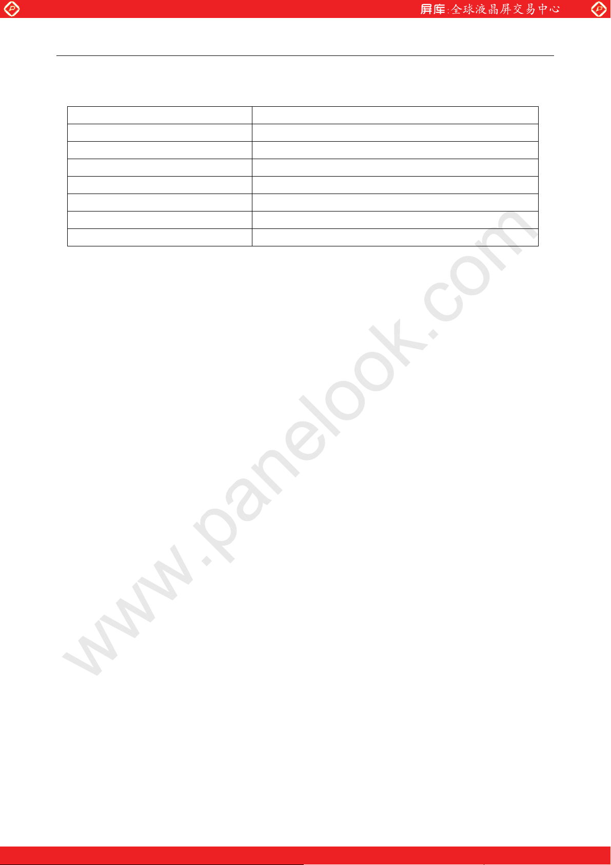
gThe measurement Equipment are as shown below table.
Item Measuring Equipment
Viewing Angle Pritchard 1980A by Photo Research Corp.
Contrast Pritchard 1980A by Photo Research Corp.
Response Time LCD-5000 by Ohtsuka Elec
White Luminance Pritchard 1980A by Photo Research Corp.
Luminance Uniformity Pritchard 1980A by Photo Research Corp.
Chromaticity LCD-5000 by Ohtsuka Elec
White Balance LCD-5000 by Ohtsuka Elec
The measurement is to be done after 30 minutes of Power-on of Back Light.
gUnless otherwise specified, the ambient conditions are as following.
www.panelook.com
Ambient Temperature˖25f2 (ć)
Ambient Humidity˖ 25-85 (%)
Atmospheric Pressure˖86-106 (kPa)
- - 7
One step solution for LCD / PDP / OLED panel application: Datasheet, inventory and accessory!
www.panelook.com
Page 8
Global LCD Panel Exchange Center
CJM16C0101
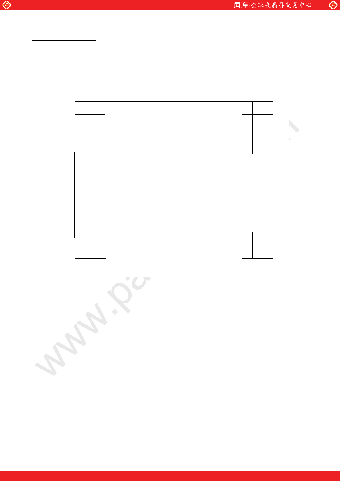
5.Color Arrangement
1ST
LINE
R G B R G B
R G B R G B
R G B R G B
R G B R G B
www.panelook.com
1280 TH
TRIAD
R G B R G B
1024TH
LINE
R G B R G B
- - 8
One step solution for LCD / PDP / OLED panel application: Datasheet, inventory and accessory!
www.panelook.com
Page 9
Global LCD Panel Exchange Center
CJM16C0101
6.Block Diagram
www.panelook.com
- - 9
One step solution for LCD / PDP / OLED panel application: Datasheet, inventory and accessory!
www.panelook.com
Page 10
Global LCD Panel Exchange Center
CJM16C0101
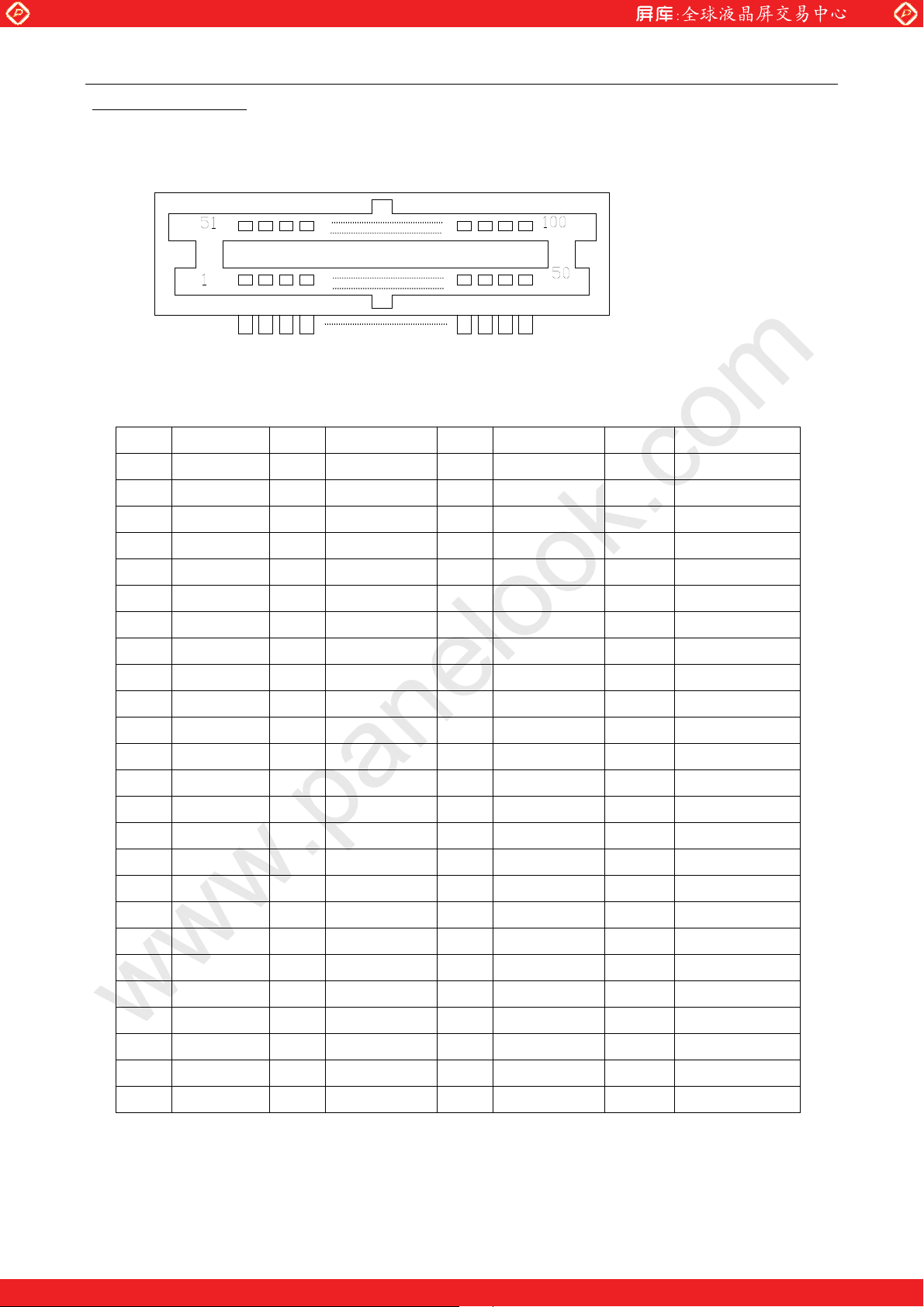
7. Signal Interface
(1) Signal connector
J1: PhEC100R-R211 (BURNDY, mate with PHEC100P-R211)
Front View
PIN# Signal name PIN# Signal name PIN# Signal name PIN# Sign name
www.panelook.com
1 VSYNC 26 GND 51 GND 76 OG5
2 GND 27 OG6 52 DOTCLK 77 GND
3 HSYNC 28 GND 53 GND 78 OG7
4 GND 29 EB2 54
DISP TIMING
79 GND
5 ER2 30 EB0 55 GND 80 EB3
6 ER0 31 EB4 56 ER3 81 EB1
7 ER4 32 GND 57 ER1 82 EB5
8 GND 33 EB6 58 ER5 83 GND
9 ER6 34 GND 59 GND 84 EB7
10 GND 35 OB2 60 ER7 85 GND
11 OR2 36 OB0 61 GND 86 OB3
12 OR0 37 OB4 62 OR3 87 OB1
13 OR4 38 GND 63 OR1 88 OB5
14 GND 39 OB6 64 OR5 89 GND
15 OR6 40 GND 65 GND 90 OB7
16 GND 41 RESERVE 66 OR7 91 GND
17 EG2 42 GND 67 GND 92 RESERVE
18 EG0 43 RESERVE 68 EG3 93 GND
19 EG4 44 DPOL 69 EG1 94 PPOL
20 GND 45 N.C. 70 EG5 95 N.C.
21 EG6 46
BRIGHTNESS
71 GND 96 CONTRAST
22 GND 47 FRCEN 72 EG7 97 DTREN
23 OG2 48 RESERVE 73 GND 98 -BL-OFF
24 OG0 49 GND 74 OG3 99 GND
25 OG4 50 +5V 75 OG1 100 +5V
- - 10
One step solution for LCD / PDP / OLED panel application: Datasheet, inventory and accessory!
www.panelook.com
Page 11
Global LCD Panel Exchange Center
CJM16C0101
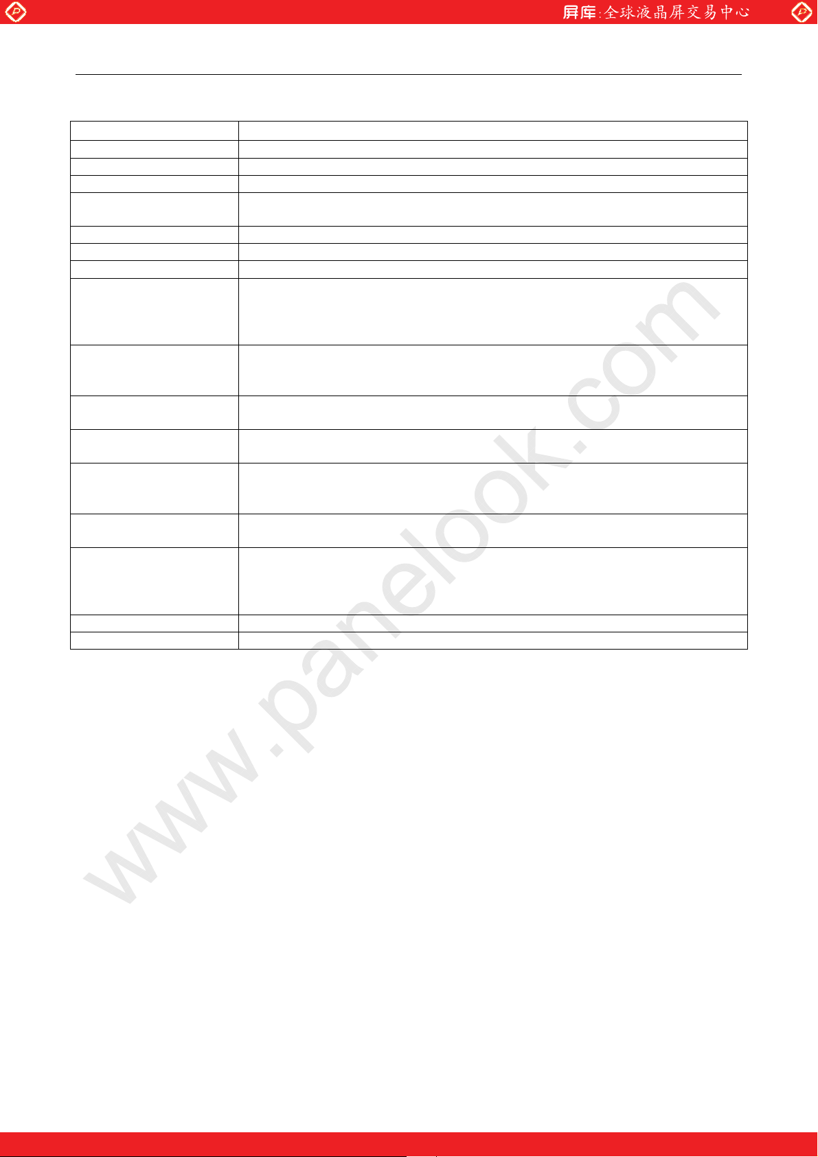
INTERFACE SIGNAL DESCRIPTION
SIGNAL NAME DESCRIPTION
RE(7:0),RO(7:0) Red data 7(MSB) to 0 (LSB)
GE(7:0),GO(7:0) Green data 7(MSB) to 0 (LSB)
BE(7:0),BO(7:0) Blue data 7(MSB) to 0 (LSB)
DOTCLK
DISP TIMING LCD Display Timing signal
VSYNC Vertical Synchronization
HSYNC Horizontal Synchronization
DPOL
(Note.1)
PPOL
(Note.1)
BRIGHTNESS
CONTRAST
FRCEN
(Note.1)
DTREN
(Note.1)
-BL-OFF
(Note.1)
+5V +5V output for test use.
GND Signal GND.
(Note.1) If this signal is not used, the signal should be open.
Dot Clock Input-The falling edge should be used to sample the other LCD
signal.
Display Timing Signal Polarity Control-This signal controls the polarity of
‘DISP TIMING’. The ‘DISP TIMING’ signal is high active when “DPOL’ is
high, low active when ’DPOL’ is low. This signal is pulled-up internally by 10k
ohm.
Pixel Data Polarity Control-This signal is used to indicate the digital video
data polarity.
This signal is pulled-up internally by 10k ohm.
Shall be connected with variable volume (Max=0 ohm, Min=10kohm)
Between this signal line and GND.
Shall be connected with variable volume (Max=0 ohm, Min=10k ohm)
between this signal line and GND.
Frame Rate Control Enable-When this signal is high, the Frame Rate Control
function is enabled.
This signal is pulled-up internally by 10k ohm.
Dithering Enable-When this signal is high, the Dithering function is enabled.
This signal is pulled-up internally by 10k ohm.
Back Light Off input-This signal is used to control the back light by external
input. When this signal is low, back light is off(pre-heating)and DC/DC
converter on the IF card is disabled.
This signal is pulled-up internally by 10k ohm.
www.panelook.com
- - 11
One step solution for LCD / PDP / OLED panel application: Datasheet, inventory and accessory!
www.panelook.com
Page 12
Global LCD Panel Exchange Center
CJM16C0101
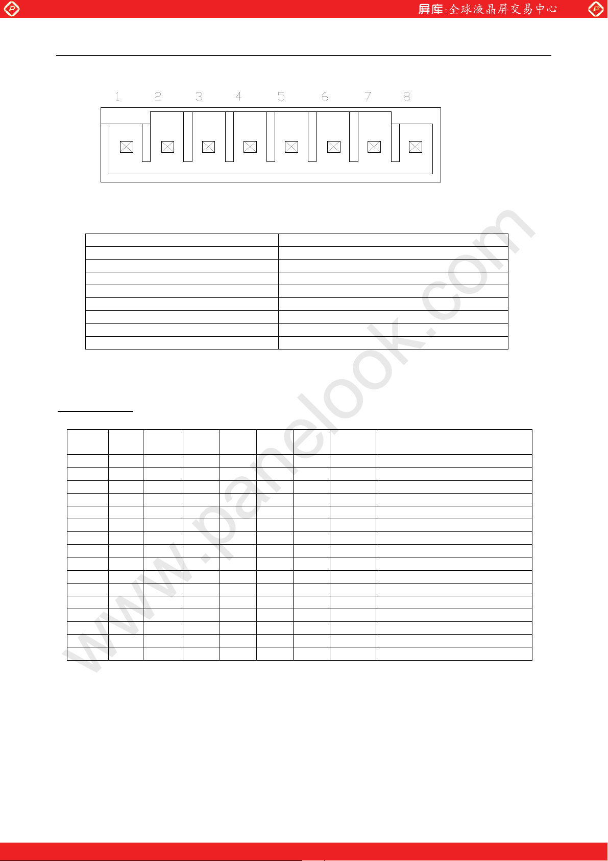
(2) Power connector
Compatible with ITSX80
J10: S8B-PH-SM3(JST, mate with PHR-8)
PIN# Signal name
8 +5V
7 +5V
6 GND
5 GND
4 +12/20V
3 +12/20V
2 AGND
1 AGND
www.panelook.com
8. Color Code
BIT7
(MSB)
ER7 ER6 ER5 ER4 ER3 ER2 ER1 ER0 Red of even column pixels.
OR7 OR6 OR5 OR4 OR3 OR2 OR1 OR0 Red of odd column pixels.
EG7 EG6 EG5 EG4 EG3 EG2 EG1 EG0 Green of even column pixels.
OG7 OG6 OG5 OG4 OG3 OG2 OG1 OG0 Green of odd column pixels.
EB7 EB6 EB5 EB4 EB3 EB2 EB1 EB0 Blue of even column pixels.
OB7 OB6 OB5 OB4 OB3 OB2 OB1 OB0 Blue of odd column pixels.
H H H H H H H H 255(brightest)
H H H H H H H L 254
H H H H H H L H 253
H H H H H H L L 253
L L L L L L H H 3
L L L L L L H L 2
L L L L L L L H 1
L L L L L L L L 0(darkest)
BIT6 BIT5 BIT4 BIT3 BIT2 BIT1
BIT0
(LSB)
Color code
- - 12
One step solution for LCD / PDP / OLED panel application: Datasheet, inventory and accessory!
www.panelook.com
Page 13
Global LCD Panel Exchange Center
CJM16C0101
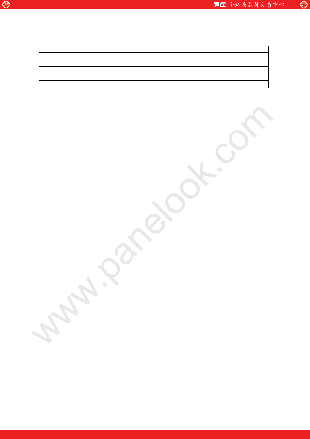
9.Signal Specification
R/G/B,DTCLK,DSPTMG,H/VSYNC signal specification
Parameter Condition Min. Max. Unit
Vih
Vil Low level input voltage 0 0.8 V
Iih High level input current
Iil Low level input current
High level input voltage 2.0 VDD+0.3 V
www.panelook.com
ˉ
ˉ
50 µA
-50 µA
- - 13
One step solution for LCD / PDP / OLED panel application: Datasheet, inventory and accessory!
www.panelook.com
Page 14
Global LCD Panel Exchange Center
CJM16C0101
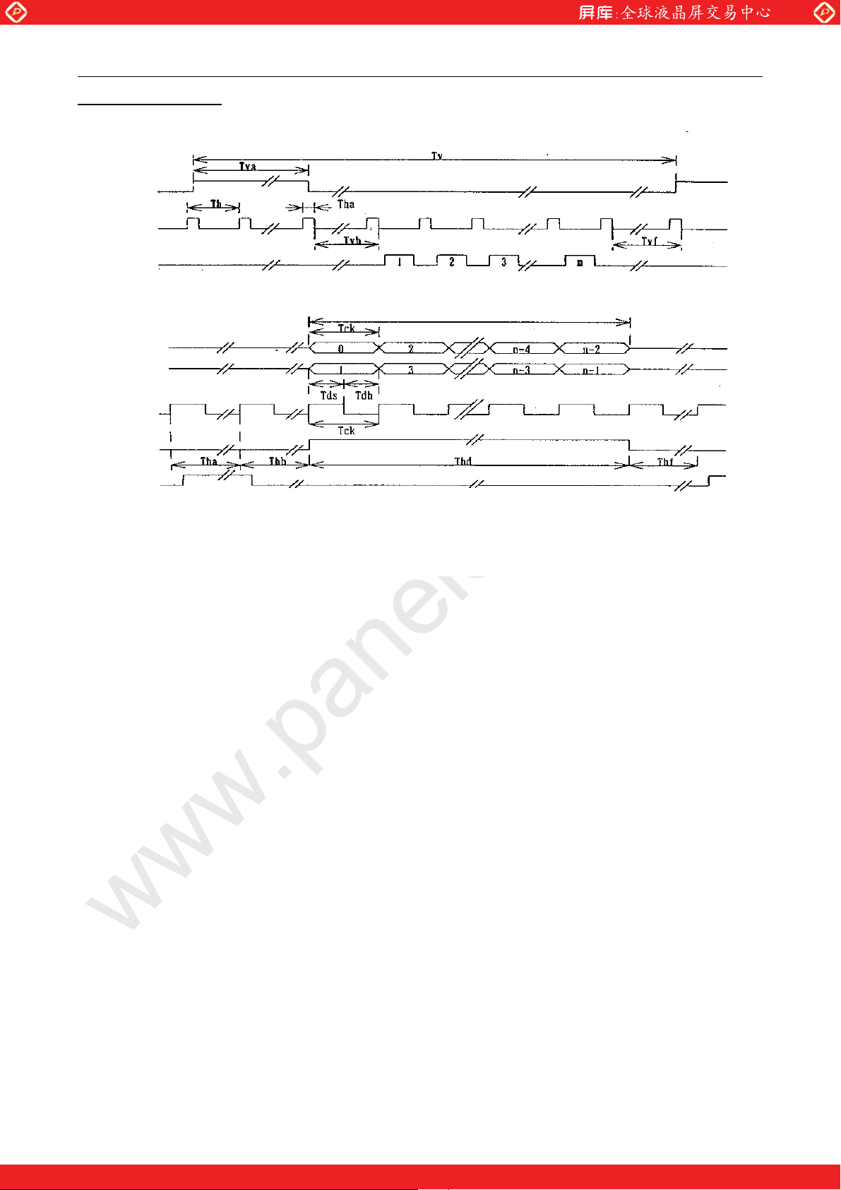
10.Interface Timing
VSYNC
HSYNC
DSPTMG
Vsync,Hsync and Display Timing
VIDEO(EVEN)
VIDEO(ODD)
DOTCLK
www.panelook.com
Thd
DSPTMG
HSYNC
Video signal and Dot clock
- - 14
One step solution for LCD / PDP / OLED panel application: Datasheet, inventory and accessory!
www.panelook.com
Page 15
Global LCD Panel Exchange Center
CJM16C0101
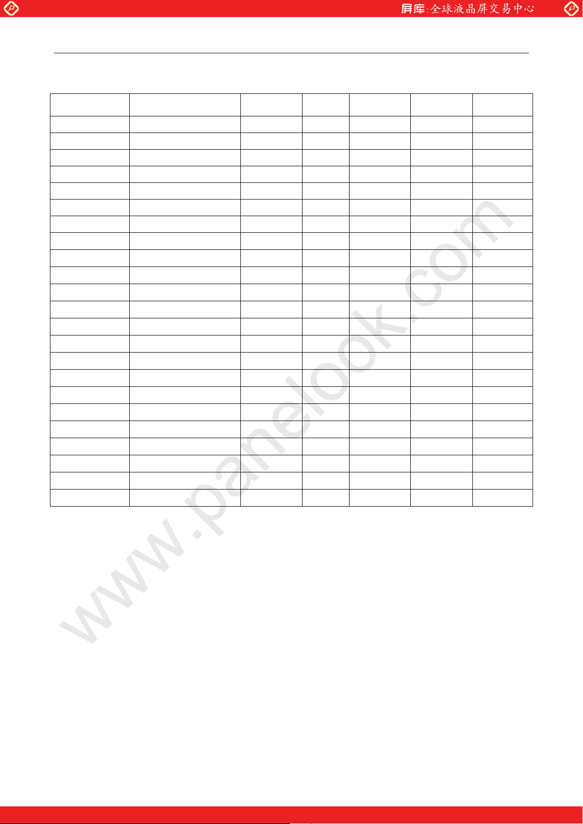
-1280×1024/60Hz, Dot Clock 55.76 MHz
Signal Item Symbol MIN. TYP. MAX. Unit
DTCLK Freq. Fdck 55.76 57 MHz
DTCLK Freq. Tck 17.5 17.9 ns
DTCLKWH Clock high width Twch 4 ns
DTCLKWL Clock low width Twcl 4 ns
+V-Sync Frame Rate 1/Tv 56.25 60 61 Hz
+V-Sync Cycle Tv 16.39 16.67 17.78 ms
+V-Sync Cycle Tv 1020 1056 lines
+V-Sync active level Tva 15.78 47.3 µs
+V-Sync active level Tva 1 3 lines
+V-Sync V-back porch Tvb 7 26 63 lines
+V-Sync V-front porch Tvf 1 3 lines
www.panelook.com
+DSPTMG V-Line m 1024 lines
+H-Sync Scan Rate 1/Th 63.36 KHz
+H-Sync Cycle Th 15.78 µsec
+H-Sync Cycle Th 820 880 Tck
+H-Sync active level Tha 1.79 µsec
+H-Sync active level Tha 10 100 Tck
+H-Sync Back porch Thb 8 127 Tck
+H-Sync Front porch Thf 8 13 Tck
+DSPTMG Display Thd 11.48 µsec
+VIDEO V-ODD/EVEN n 640 Tck
+VIDEO Data setup Tds 3 ns
+VIDEO Data hold Tdh 5 ns
- - 15
One step solution for LCD / PDP / OLED panel application: Datasheet, inventory and accessory!
www.panelook.com
Page 16
Global LCD Panel Exchange Center
CJM16C0101
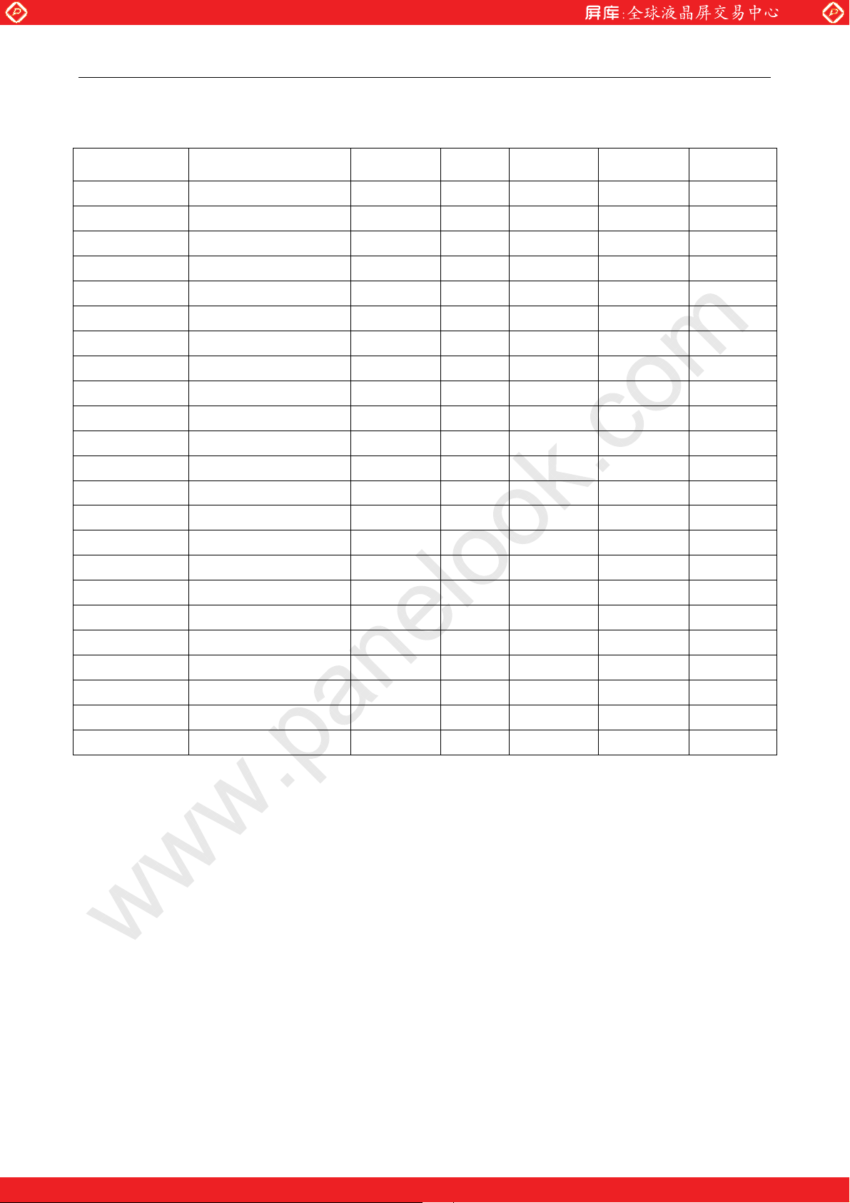
-1280h1024/60Hz,Dot Clock 50MHz
Signal Item Symbol MIN. TYP. MAX. Unit
DTCLK Freq. Fdck 50 MHz
DTCLK Freq. Tck 20 ns
DTCLKWH Clock high width Twch 4 ns
DTCLKWL Clock low width Twcl 4 ns
+V-Sync Frame Rate 1/Tv 57.74 Hz
+V-Sync Cycle Tv 17.32 ms
+V-Sync Cycle Tv 1056 lines
+V-Sync active level Tva 49.6 µs
+V-Sync active level Tva 3 lines
+V-Sync V-back porch Tvb 26 lines
www.panelook.com
+V-Sync V-front porch Tvf 3 lines
+DSPTMG V-Line m 1024 lines
+H-Sync Scan Rate 1/Th 60.98 KHz
+H-Sync Cycle Th 16.4 µsec
+H-Sync Cycle Th 820 Tck
+H-Sync active level Tha 2 µsec
+H-Sync active level Tha 100 Tck
+H-Sync Back porch Thb 67 Tck
+H-Sync Front porch Thf 13 Tck
+DSPTMG Display Thd 12.8 µsec
+VIDEO V-ODD/EVEN N 640 Tck
+VIDEO Data setup Tds 3 ns
+VIDEO Data hold Tdh 5 ns
- - 16
One step solution for LCD / PDP / OLED panel application: Datasheet, inventory and accessory!
www.panelook.com
Page 17
Global LCD Panel Exchange Center
CJM16C0101
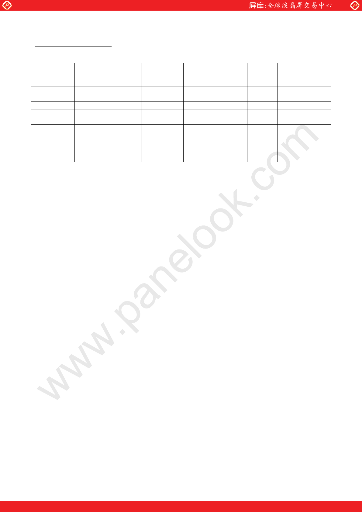
11.Power Requirement
SYMBOL PARAMETER Min. Typ. Max. Unit CONDITION
VDD Logic/LCD Drive
Voltage
IDD Logic Control
Current
VBL Backlight Voltage 10.8 12.0/20.0 21 V
IBL Backlight Current 2.5
PDD+PBL Total Power 30 33 W
VDDrp,
VBLrp
VDDns,
VBLns
Note:1.This requirements shall be met with ‘All black pattern’.
2.Maximum current does not include noise nor ripple current.
3.Voltage variation includes the ripple voltage.
Allowable Logic/LCD
Drive Ripple Voltage
Allowable Logic/LCD
Drive Ripple Noise
www.panelook.com
4.75 +5.0 5.25 V
0.6 A
A 12V
1.5
100 mVp-p
150 mVp-p
20V
- - 17
One step solution for LCD / PDP / OLED panel application: Datasheet, inventory and accessory!
www.panelook.com
Page 18
Global LCD Panel Exchange Center
CJM16C0101
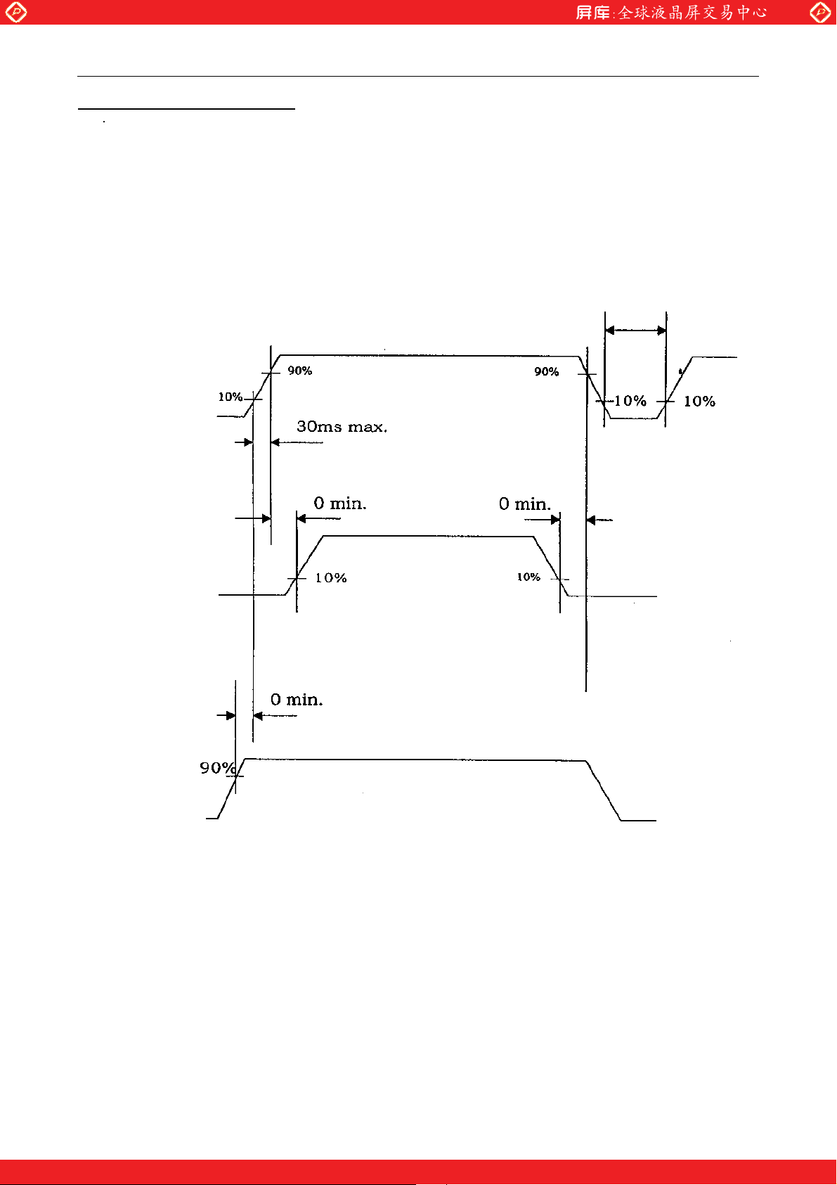
12.Power ON/OFF sequence
VDD
www.panelook.com
10ms min
0V
Signals
0V
VBL
0v
- - 18
One step solution for LCD / PDP / OLED panel application: Datasheet, inventory and accessory!
www.panelook.com
Page 19
Global LCD Panel Exchange Center
CJM16C0101
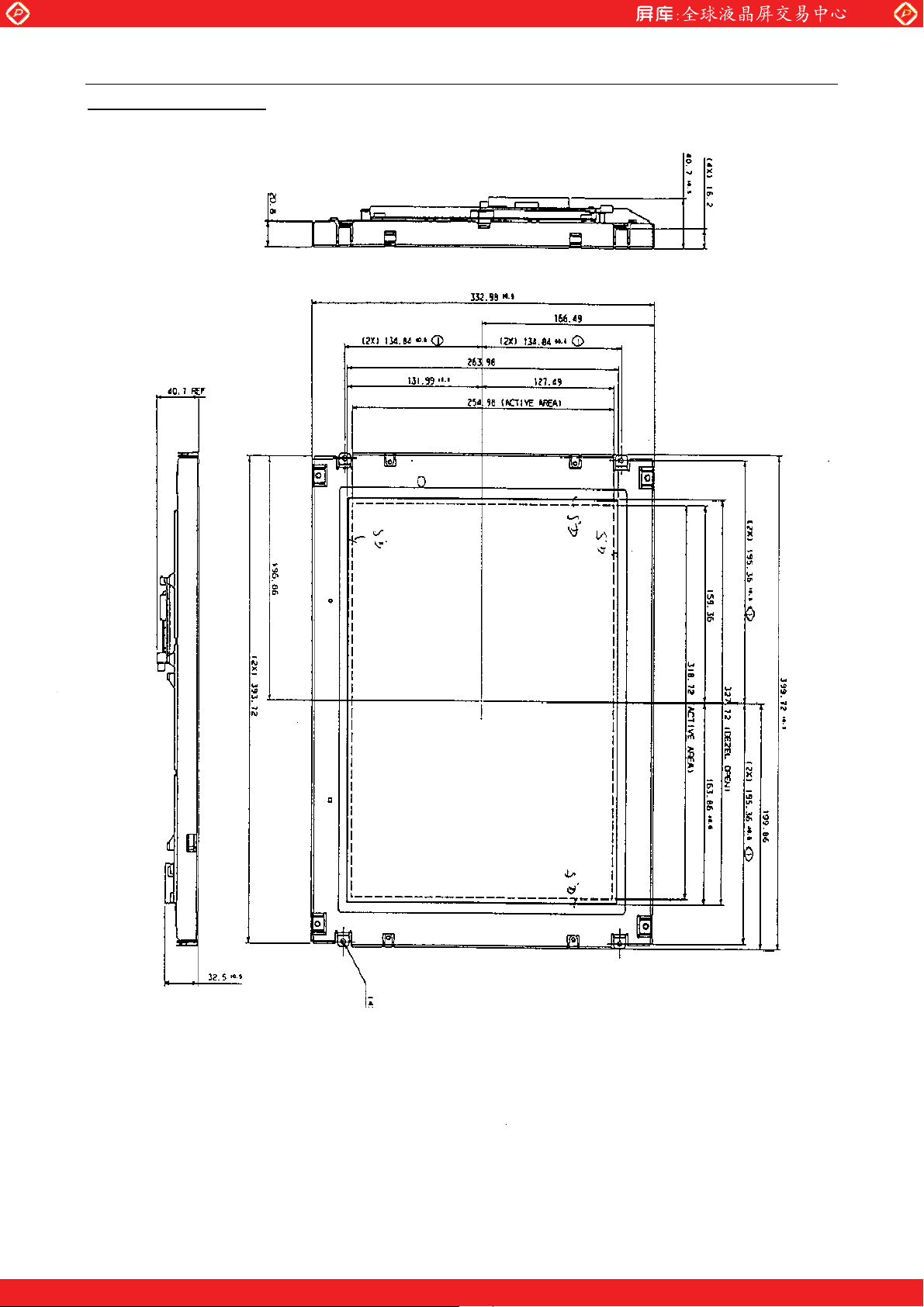
13.Outline Dimension
www.panelook.com
Front view
- - 19
One step solution for LCD / PDP / OLED panel application: Datasheet, inventory and accessory!
www.panelook.com
Page 20
Global LCD Panel Exchange Center
CJM16C0101
www.panelook.com
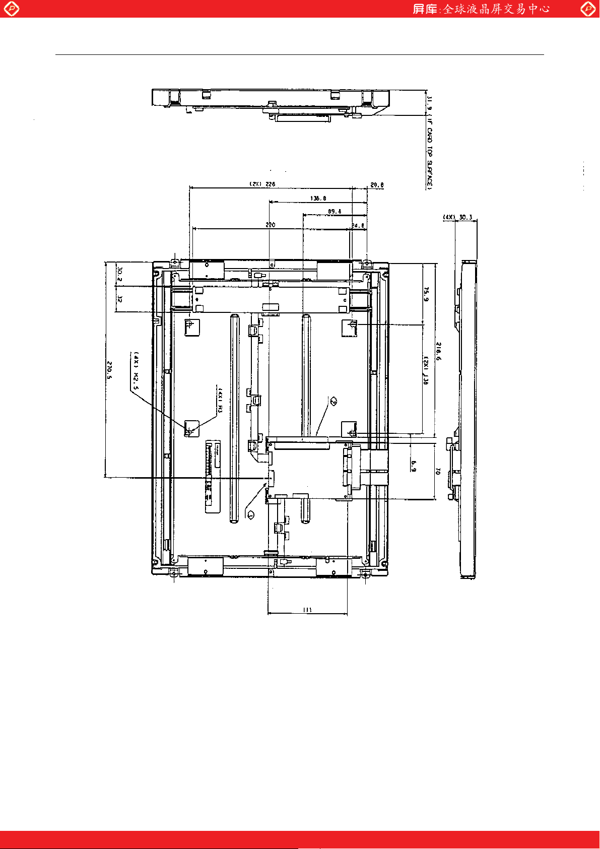
Rear view
- - 20
One step solution for LCD / PDP / OLED panel application: Datasheet, inventory and accessory!
www.panelook.com
Page 21
Global LCD Panel Exchange Center
CJM16C0101
14. NOTE
14.1 FOR SAFETY
LCD module is generally designed with precise parts to achieve light weighted thin mechanical
dimensions.
In using our Modules, make certain that you fully understand and put into practice the warnings
and safely precautions detailed in engineering information.
Refer to individual specifications and technical data for more detailed technical information.
1ˊ SPECIAL PURPOSES
A) JCT'S Standard LCD Modules have not been customized for operation in extreme
environments or for use in applications where performance failures could be life-threatening or
otherwise catastrophic.
B) Since JCT’S Standard LCD Modules have not been designed for operation in extreme
environments, they must never be used in devices that will be exposed to abnormally high
levels of vibration or shock which exceed JCT Corp. published specification limits.
C) In addition, since JCT Standard LCD Modules have not been designed for use in applications
where performance failures could be life-threatening or catastrophic, they must never be
installed in aircraft navigation control systems ǃcritical industrial process control systems(e.g.
those involved in the production of nuclear energy) or in critical medical device or patient
lift-support systems.
2ˊ DISASSEMBLING OR MODIFICATION
DO NOT DISASSEMBLE OR MODIFY the module. It may damage sensitive parts inside LCD
module, and may cause scratches or dust on the display.
JCT Corp. doses not warrant the module, if customer disassembled or modified it.
3ˊ BREAKAGE OF LCD PANEL
DO NOT INGEST liquid crystal material, DO NOT INHALE the material with skin, if LCD panel is
broken and liquid crystal material spills out.
If liquid crystal material comes into mouth or eyes, rinse mouth or eyes out with water immediately.
If this material contact with skin or cloth, wash it off immediately with alcohol and rinse thoroughly
with water.
4ˊ GLASS OF LCD PANEL
BE CAREFUL WITH CHIPS OF GLASS THAT MAY CAUSE INJURING FINGERS OR SKIN, when
the glass is broken.
5ˊ ELECTRIC SHOCK
DISCONNECT POWER SUPPLY before handling LCD module.
DO NOT TOUCH the parts inside LCD module and the fluorescent lamp’s connector or cables in
order to prevent electric shock, because high voltage is supplied to these parts from the inverter unit
while power supply is turned on.
6ˊ ABSOLUTE MAXIMUM RATINGS AND POWER PROTECTION CIRCUIT
DO NOT EXCEED the absolute maximum rating values under the worst probable conditions caused
by the supply voltage variation, input voltage variation, variation in parts’ constants, environmental
temperature, etc, otherwise LCD module may be damaged.
Employ protection circuit for power supply, whenever the specification or TD specifies it.
Suitable protection circuit should be applied each system design.
7ˊ DISPOSAL
When dispose LCD module, obey to the applicable environmental regulations
www.panelook.com
- - 21
One step solution for LCD / PDP / OLED panel application: Datasheet, inventory and accessory!
www.panelook.com
Page 22
Global LCD Panel Exchange Center
CJM16C0101
14.2 For Designing the System
(1) LCD module should be assembled to the system by using all mounting holes specified in this
specification and with the specified screws.
(2) DO NOT GIVE high voltage to “Low Voltage” side of the FL.
For example, DO NOT USE a flowing inverter which gives high voltage to “Low Voltage” side. That’s
because it has a possibility to burn or smoke around the FL.
(3) Make sure to connect correctly high-voltage wire and low-voltage wire between FL tube and inverter
unit.
(4) Input FL starting voltage (V
If it were less than one second, it may cause unstable operation of FL.
Please adjust inverter circuit parameters, such as capacitor, resistor, to assure the display quality is
maintained.
There is a possibility that flicker is observed by the interference of LCD operating signal timing and
FL driving condition (especially driving frequency).
(5) In case of severe environmental condition like outdoor usage, a proper transparent protective cover
(lens) over LCD module is recommended to apply in order to prevent scratches, and invasion of
dust, water, etc., from the system’s window onto LCD module.
Ultra-violet ray cut filter is recommended to apply onto LCD module for outdoor operation. Strong
ultra-violet ray may cause damage the panel.
(6) Design the system not to display same pattern for a long time in order to prevent image sticking on
the panel. Note that incorrect sequence of power supplies and input signals may cause the sticking
on the panels, too.
www.panelook.com
) should not be less than one second.
SFL
- - 22
One step solution for LCD / PDP / OLED panel application: Datasheet, inventory and accessory!
www.panelook.com
Page 23
Global LCD Panel Exchange Center
CJM16C0101
14.3 For Installation in Assembly
(1) The C-MOS LSI used in LCD module is very sensitive to ESD (Electro-static Discharge).
Ambient humidity of working area is recommended to be higher than 50%RH.
Person handling LCD modules should be ground with wrist band. Tools like soldering iron and screw
driver, and working benches should be grounded.
The grounding should be done through a resister of 0.5-1 Mohms in order to prevent spark of ESD.
(2) Reduce dust level in working area. Especially the level of metal particle should be decreased. Use
finger stalls or soft and dust-free gloves in order to keep clean appearance of LCD module when
handle for incoming inspection and assembly
(3) When remove protection film from LCD panel, peer off the film slowly (more than three second from
the edge of the panel to minimize ESD, using a soft-pointed tweezers covered by Teflon or adherent
tape.
(4) When LCD panel becomes dirty, wipe of the panel surface softly with absorbent cotton or another
soft cloth.
If necessary, breathe upon the panel surface and then wipe off immediately and softly again.
If the dirt can not be wiped off, absorbent cotton wetted a little with normal-hexane or petroleum
benzene can be used for wiping the panel.
Be careful not to spill this solvent into the inside of LCD module. Driver ICs and PCB area used
inside LCD module may be damaged by the solvent.
(5) AVOID THE DEWING OF WATER CONDENSATION
Wipe off a spot or spots of water of mist and chemicals of mist on LCD panel softly with absorbent
cotton or another cloth as soon as possible if happened, otherwise discoloration or stain may be
caused. If water invade into LCD module may cause its damages.
(6) Do not expose LCD module to the gas (which is not normally contained in the atmosphere),it may
cause mis-operation or defects.
(7) DO NOT APPLY MECHANICAL FORCES.
Do not bend or twist LCD module even momentary when LCD module is installed an enclosure of
the system. Bending or twisting LCD module may cause its damages.
Make sure to design the enclosure that bending/twisting forces are not applied to LCD module
when it is installed in the system.
Refrain from strong mechanical shock like dropping form the working bench or knocking against
hard object.
These may cause glass of the panel crack, damage of FL or other mis-operation.
(8) Refrain from excessive force like pushing the surface of LCD panel. This may cause damage of the
panel or electrical parts on PCB.
(9) Do not put heavy object such as tools, books, etc., and do not pile up LCD modules.
Be careful not to touch surface of the polarizer laminated to the panel with any hard and sharp
object. The polarizer is so soft that it can easily scratched, even the protect film covers it.
(10) When inserting or disconnecting the connectors to LCD module, be sure not to apply force against
PCB, nor connecting cables, otherwise internal connection of PCB and TAB drivers may be
damaged.
Do not fasten screws while putting cables like those for interface or FL between LCD module and
the enclosure.
Make sure to insert the module FL connector to the inverter connector in correct position.
If incorrect, this may cause smoke or burn or electrical parts by high voltage of FL circuit.
www.panelook.com
- - 23
One step solution for LCD / PDP / OLED panel application: Datasheet, inventory and accessory!
www.panelook.com
Page 24
Global LCD Panel Exchange Center
˖
CJM16C0101
(11) Be careful not to pull the FL cables of the backlight in order to avoid mechanical damage in FL
lamp and soldering area.
Be careful not to pull or not to hurt the FPC (Flexible Printed Circuit) cables.
(12) Power supplies should always be turned off in assembling process.
Do not connect or disconnect the power cables and connectors with power applied to LCD module.
This may cause damage of module circuit.
The signal should be applied after power is turned on. And the signal should be removed before
power supplies are turned off.
14.4 For Transportation and storage
(1) Do not store LCD module in high temperature, especially in high humidity for a long time
(approximately more than one month).
It is recommended to store LCD module where the temperature is in the range of 0 to 35
degrees Celsius and the relative humidity is lower than 70%.
(2) Store LCD module without exposure to direct sunlight or fluorescent lamps in order to prevent
the module from strong ultra violet ray.
(3) Avoid condensation of water on LCD module; otherwise it may cause mis-operation or defects.
Keep away LCD module from such ambient.
(4) In case of transportation of storage after opening the original packing. LCD module is
recommended to be repacked into original packaging with the same method, especially with
the same kind of desiccant.
www.panelook.com
CAUTION
1. JCT is not responsible for any undesirable result caused by the
abnormal operating by users.
2. For improvement, JCT reserves the right to change or alter any or all
specification or design this product and the content of the specification
without any prior notice.
3. No part of the product and the specification may be reproduced,
transmitted, transcribed, stored in a retrieval system, or translated into
any language in any form by any means. Otherwise, this will be
considered as a copyright infringement.
- - 24
One step solution for LCD / PDP / OLED panel application: Datasheet, inventory and accessory!
www.panelook.com
 Loading...