


User Manual
INTEGRA

Table of contents
Maintenance 3
Important safety instructions for inst allation 3
Important safety instructions for use 3
Equipmetn use 3
Description 4
Technical charac teris tics 4
Installation 5
Fitting the casing 5
Important considerations f or start-up 5
Oper ating 6
*Anti-intrusion f unction 7
Option sw itch 7
Input switch 8
Buttons 8
Times 8
Light indicators 8
Input light indicators 9
Parameter configuration from programmer 9
Programming 9
Programming with ends of runand automatic close 9
Opti onal cards 10
Receiver card 10
Traffic light card 10
This has t hree diff erent functions (with s witc h* to OFF) 10
Traffic control (with switch* to ON) 11
Signal card 11
RADIOBAND/RCS card 11
Magnetic detector c ard 11
Regulatory Data 12
EU Declaration of conformity 12
jcmtechnologies
2

Maintenance
Important safety instructions for installation
Disconnect the power supply whenever you proceed to the installation or repair
of the control panel.
•Before installing the panel, remove all unnecessary ropes or chains and disable any equipment such as locks that is not neces-
sary for theautomatic operation.
•Before installing the panel, check that the doo r is in good mechanical condition, correctly balanced and that it opens and
closes correctly.
•Install the manual unlocking devicea t a height lower than 1.8m.
•Install any permanent control next to the door away from any moving part and at a minimum height of 1.5m.
•An easily accessibledisconnection devicem ust be fitted to thewiring for permanently connected equipment. This device must
ensurethe single-pole cut-off of power. It is wise for this to be an emergencyswitch/isolator.
•Wherethe panel issupplied without an emergency sto p button, this must be incorporated on installation, connected to the
STOP terminal.
•For correct use of thesecurity edge, this must never be activated when thedo or is fully closed. It is wiseto install theends of run
before a ctivating theedge.
•This equipment can only be handled by a specialist f itter, bymaintenance staf f or by a suitably tra ined operator.
•To connect the power supply and motor wiring, 2.5 mm2 section terminals must be used.
•Fuses must only be handled when the appliance is disconnected from the ma ins.
•The instructions for using this equipment must remain in the possession of theuser.
•European door normative EN 124 53 and EN 12445 specify the following minimum protection a nd door safety levels:
- for single-family hom es, prevent thedo or being able to come into contact with any object o r limit thecontact force (e.g. secur-
ity edge) and, in theevent o f automatic closure, a presencedetector (e.g. photocell) must be added.
- for communal a nd public installations, prevent the door being ableto come into contact with any o bject or limit the contact
force (e.g. security edge) and detect presence(e.g. photocell).
Important safety instructions for use
•Do not allow children to play with the door controls.
•Keep the remote controls out of the reach of children.
•Watch thedoor movement and keep people a way until the door is f ully open or closed.
•Precaution when operating the m anual unlocking device, as the door may suddenly fall due to the bad condition of thesprings
or door unbalance. Details on how to use the manual unlocking device must be provided by the ma nufacturer or the device
installer.
•Examine theinstallation frequently, especiallythe cables, springs and supports, to detect signs of wear, damag e or unbalance.
Do not use the door if repair work or adjustments are required, as this may cause dam age.
Equipmetn use
Designed for t he automation of garage doors as per t he general description. Not guaranteed for other uses.
The manufacturer reserves the right to modify equipment specifications without prior notice.
jcmtechnologies
3
Description
Control panel for the control of three-phase motors to 3CV at 400V and single-phase motors to 1.5CV at 230V for industrial
doors. Allows for dead-man open and close operations, automatic dead-man close operations, semi-automatic operations and
automatic operations. Connection t o portable programmer.
Technical characteristics
INTEGRA-ECO
(standard box model)
Panel supply 400V ac3N / 230V ac
Power 3CV / 1.5CV
Optional cards Receiver card, Radioband/RCS, signal, magnetic detector
24Vac output 24V ac/ 0.5A (shared with photocell test output)
Photocellautotest output 24V ac/ 0.5A (shared with security device output)
Auxiliary contact outlet Electro-brake / Electro-lock/ Garage light
230V acoutlet
Operating temperature -20ºC to +85ºC
Sizes 225x195x85 mm 305x225x126 mm
Airtightness IP54 IP56
Equipment category Class II
Limited to (0.05A, 11W) powered at 400V
Limited to (3A, 600W) powered at 230 Vac
INTEGRA
(Industrial boxmodel)
jcmtechnologies
4

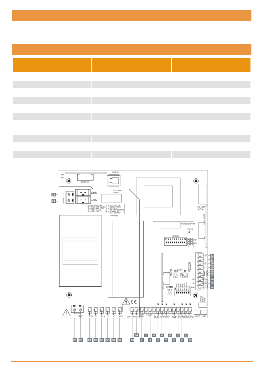
1 Test for security parts 14 Common securities 27 R(N) Power supplyconnection
230V/400V or neutral
2 Common for security part test
and 24Vacoutlet
3 24Vac outlet 16 Security Open contact (NC) 29 T(L) Power supplyconnection
4 Common ends of run and stop 17 Security Close edge (resistive
5 End of run Close ( NC) 18 Security Close edge (resistive
6 End of run Open (NC) 19 Sensor hallpower (+) 12Vd-
7 Stop button (NC) 20 “Sensor hall” HA signalinlet. 33 Auxiliary contact outlet
8 Common temperature contact 21 "Sensor hallpower" (-) 12Vd-
9 Temperature contact (NC) 22 “Sensor hall” HB signalinlet
10 Common buttons 23 230V acoutlet
11 Alternative button (NO) 24 230V acoutlet
12 Close button ( NO) 25 Earthing terminal
13 Start button (NO) 26 Earthing terminal
15 Security Close contact (NC) 28 S Power supply connection
400V
230V/400V
30 U triple phase motor con-
contact 8k2)
contact 8k2)
c/+5Vdcdepending on switch
c/5Vdc depending on switch
nection/ single phase
31 V triple phase motor con-
nection/ single phase
32 W(C) triple phase motor con-
nection/ common single phase
34 Auxiliary contact outlet
Warning: Where working with 230V connection, turn the switch to 230Vac, and
where working with 400V three-phase connection, turn the switch to 400Vac.
Installation
Any handling of the panel for installation must be carried out with the power supply disconnected.
Fitting the casing
•Pa rts: front casing and conta iner box.
•Unscrew thesecuring points. Insert thecables through thelower holes.
Important considerations for start-up
Check that the Open button opens and the Close butt on closes. Wherethis is not the c ase, invert motor cables U and V.
Any optional cards must be connected to t he panel with t he power s upply disconnected.
jcmtechnologies
5

Operating
Open
(OPEN)
Close
(CLOSE)
Start
(START)
Temper ature
(TEMP)
Stop
(STOP)
Ends of run
(FC.CL / F C.OP)
Security contact
(SEC.CL / SEC.OP)
Security edge
(SEC.EDGE)
24 Vac output
Auto-test output
(TEST. SEC)
Auxiliary Contact
(Aux. Contact)
Contact normallyopen to open. If pressed during the closing operation it stops and
opens (untilthe end of the limit switch). Acts as “Dead-Man” if kept pressed down with
Option 3 of the options switch triggered.
Contact normallyopen to close. If it is pressed while the door is opening, it stops. Acts as
“Dead-Man” if kept pressed down with Option 2of the options switch triggered.
Contact normallyopen to open and close. The first press opens, the second press
stops (until the limit switch) and the third closes. If pressed during the closing operation
it stops and inverts (untilthe end of the limit switch). The Start contact onlyacts as an
open button when using a traffic light card with traffic control enabled.
Contact normallyclosed for connection to a temperature sensor for the motor . When it
indicates that the motor has exceeded the security limit, the operation willstop until it
has cooled. Where not used, turn option 4 (TEMP) on the input switch to ON.
Contact normallyclosed. Thisdetains the operation on standby for a new order. Where
not used, turn option 3 (STOP) on the input switch to ON.
Contacts normallyclosed to mechanically indicate the open and closed end of run.
Where not used, turn option 1 (FC.CL) and 2(FC.OP) on the input switch to ON.
Contact normallyclosed, photocell or magnetic detector type. Thisacts by causing stoppage and partial inversion during opening and stoppage and total inversion dur ing closure. Where not used, turn option 5 (SEC.CL) and 6 (SEC.OP) on the input switch to
ON. The security close contact also acts as a close button when the vehicle has passed
if Option 10 on the options switch is enabled.
Resistive contact for resistive security edge. Thisacts on closing, causing stoppage and
inversion. Where not used, turn option 7 (SEC.EDGE) on the input switch to ON.
To power any equipment at a voltage of 24 Vacwith a maximum consumption of 0,5A
(shared with photocell test output).
24 Vac output for auto-test of security parts with a maximum consumption of 0,5A
(shared with 24Vacoutput).
Normallyopen contact that has three different functions depending on the position of
Option switches 7 and 8.
Auxiliary Contact Function Option switch 7 Option switch 8
Electro-brake: Enableselectro-brake to unblock
motor during operations.
ON OFF
Anti-intrusion function * ON ON
Electro-lock: Enables electro-lock 3 secondsbefore
the start of the opening operation.
Garage light: Enables gar age light during the door
operating time plus 2 minutes.
jcmtechnologies
6
OFF OFF
OFF ON

*Anti-intrusion function
Activates the auxiliary contact on the f ollowing cases:
•If during the opening o r closing movements, or with thedoor opened, it detects the passage of more than one vehicleby the
close safety contact (SEC.C L). If this occurs durning the opening movement, the door willf inish opening. If this occurs during
the closing, the doo r will invest up until being completely open. Thedo or remains opened, without m aking auto-colosing even if
it is activated.
•If the control panel has not given theo rder to open and closing end o f course (FC.CL) is deactivated. For example, if someone
tries to open thedo or by f orce.
Deactivation of the alarm (auxiliary contact)
•The a larm willbe disabled in any case using the buttons START, OPEN or C LOSE, o r by a transmitter programmed. The STOP
button stops the alarm when the door is wide open.
Operation
counter
An operation counter and operation limit number is fitted. On reaching the limit number
of operations, the panel switches to dead man operations and the POWER light flashes
(only INTEGRA model)
Option switch
Option
No. Lower position – OFF (default option) Upper position –ON
1 Does not close automatically Automatic closure
2 Operating normallyclose “Dead man” close*
3 Operating normallyopen “Dead man” open*
4 Operating without Pre-signal Pre-signal before handling
5 Operating without C. security close test C. security close test
6 Operating with C. securityopen test C. security open test
7 See table Auxiliary Contact Function
8 See table Auxiliary Contact Function
9 Allows for radio reverse on opening Does not allow for radio reverse on opening
10 The security close contact works are normal
* The “dead man” close and open moves the door while the button is pressed down.
The security close contact also acts asthe close
button when the vehicle has passed
jcmtechnologies
7

Input switch
Nº Opción Lower position - OFF Upper position – ON (default option)
1 (FC.CL) End of run close connected End of run close not connected
2 (FC.OP) End of run open connected End of run open not connected
3 (STOP) Stop button connected Stop button not connected
4 (TEMP) Temperature contact connected Temper ature contact non connected
5 (SEC.CL) Security Close contact connected SecurityClose contact not connected
6 (SEC.OP) Security Open contact connected Security Open contact not connected
7 (SEC.EDGE) Security Close edge connected Security Close edge not connected
Buttons
START Start/stop button
PROG Programming button
RES POS Position reset button. *
* This button performs the position reset when the panel operates using sensor hall. To do so, the
door must be totally closed and the button kept pressed down until the programming led flashes.
Times
Controlling Minimum Maximum
Motor operating 1s 180s
Wait for automatic close 1s 180s
Light indicators
POWER Indicates power
PROG Indicates programming
Number of flashes Error Code
1 flash
2 flashes
STOP/SAFETY
LAMP ( in INT EGRA
model)
Blinks indicating security activated
3 flashes
4 flashes Security edge error 4
5 flashes
6 flashes Sensor Hallerror 6
Security edge autotest
error
Security close contact
autotest
Security close contact
autotest
RADIOBAND/RCS card
autotest error
jcmtechnologies
8
1
2
3
5

Input light indicators
Function Indicates Default status
OPEN Open function Normallyoff
CLOSE Close function Normallyoff
START Open/close function Nor mally off
TEMP Temperature sensor Normallyon
STOP Stop button Normally on
FC.OP End of run Open Normally on
FC.CL End of run Close Normallyon
SEC.OP Security Open contact Nor mally on
SEC.CL Security Close contact Normallyon
Parameter configuration from programmer
There are different parameters that c an be c onfigured by portable programmer. Below is a description of the most basic. Refer
to the programmer instruction manualfor further information.
•Operation by Time: I ndicates / selects if the panel is programmed to operate by time.
•Operation by Pulses: Indicates / selects if the panel is program med to o perate by pulses.
•Oper. counter limit: I ndicates / selects the limit number of operations for the panel.
•Operation counter: Indicates thenumber of operations made to date.
•Oper.Count.Limit Active: Indicates / selects if there is a limited number of operations or not.
•Autoclosing time: Indicates / selects theseconds of automatic standby time.
•Equip.: Shows an equipment identifier.
Programming
•During programming, the control panel does not take all possible securities into account.
•Before starting any type of time programming, it is wiseto have the corresponding options correctly selected and ensurethe
cards to be used a re inserted.
•WhereRADIOBAND/RCS cards are used, thepanel must be pro grammed with the card inserted.
•Operations can be programmed indifferently using the “Test” / “Start” button or through a transmitter recorded on a pluggable
radio card for control pa nels.
•Wherea sensor hall is used, its pulse type is memorised in thepanel during programming.
Programming with ends of run and automatic close
Close the door with the limit switches (where applicable) duly connected.
Press the TIMER PROG butt on t o enter programming. The red PROG led w ith light up. T he first time TEST is pressed, the
door opens to the end of run openand the automatic standby timer begins. The second time TEST is pressed, the automatic
standby timer stops and t he door closes to t he end of run c lose.
Press the TIMER PROG butt on again to exit programming (the red PROG led will s witch off).
jcmtechnologies
9
Optional cards
Receiver card
This acts on the panel with t ransmitters, proximity keys or s mart cards in the same way as the start button.
If working with a receiver c ard f or dead-man (only available in 868MHz) and options 2 and 3 of the options switch are ON, chan-
nel 1 opens andchannel 2 closes.
In any other case, channel2 is not operative.
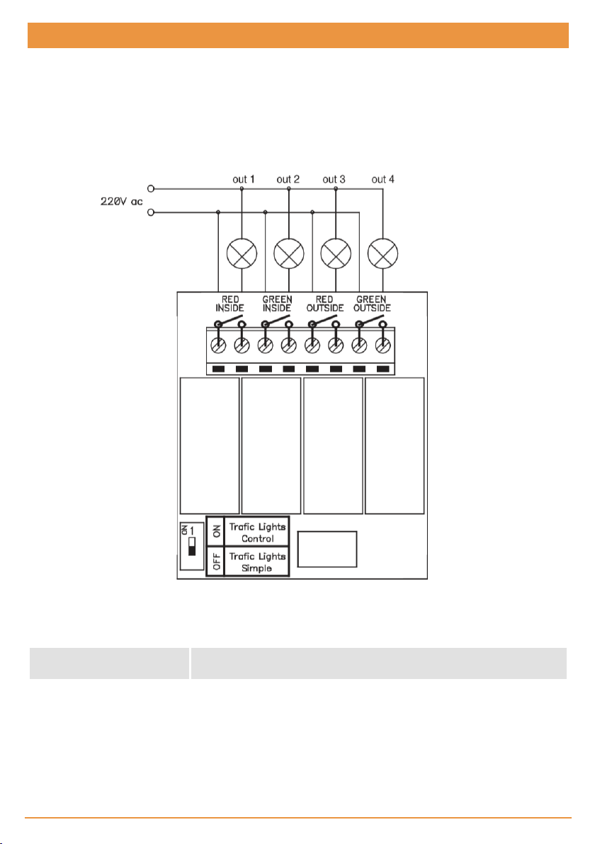
Traffic light card
This has three different functions (with switch* to OFF)
Output 1 Signal.
Output 2
Output 3 and 4
Light contact – acts for the entire time that the door is operating, plus 10
seconds
Traffic lights. Outlet 3 activates the red trafficlight that works during door
movement. Outlet 4 activates the green trafficlight that isonly lit when the
door isfullyopen
jcmtechnologies
10

Traffic control (with switch* to ON)
When this optionis activated, the traffic light interprets the Alternative contact as an outdoor open button and the Open c on-
tact as the indoor open button.
While the door remains closed, nosignals are given. When t he open order is received, the indoor and outdoor redlight contact
gives a warning f lash for 3 seconds before carryingout the operation.
As the door is opening, t he two red lights will switch on (indoor and outdoor).
Once t he door is open, t he correspondinglights will come on, depending on the act ivation point:
Pushbutton Activation Red signal Green signal
OPEN Interior open button Exterior lamp Inter ior lamp
START Exterior open button Interior lamp Exterior lamp
Before beginningthe close manoeuvre, the interior or exterior green light contact (depending on the case) w ill give an inter-
mittent pre-warningof 3 seconds. While the dooris closing, the two red lamps will light (interior/exterior).
* Warning: this switch must be enabled and disabled using when the power
supply to the panel is disconnected.
Signal card
Through the contact of a relay intermittently activated, this gives a warning3 s econds before the opening and c losing move-
ments are started and while t hey are underway.
RADIOBAND/RCS card
Optional radio-communications c ard f or security edges.
Magnetic detector card
This allows for the same f unction as an outside magnetic detector althoughwithout the need for an external power supply. It
can beused as an open button and/or security contact. It also includes the frequency changer s election and delay application
for presence deactivation.
jcmtechnologies
11

Regulatory Data
EU Declaration of conformity
The manufacturer JCM TECHNOLOGIES, S.A. declares that t he product INTEGRA cumple con los requisitos esenciales de
la Directiva RED 2014/53/UE y de la Directiva RoHS 2011/65/UE.
See website www.jcm-t ech.com/declarations/
JCM TECHNOLOGIES, SA
C/COSTA D'EN PARATGE, 6B
08500VIC (BARCELONA)
SPAIN
UM_3201266_Integra_EN_Rev01
jcmtechnologies
12
 Loading...