

User's Manual
EASY-ROLL

Maintenance
Important safety instructions for installation
Disconnect the power supply whenever you proceed to the installation or repair
of the control panel.
•The panelmust be installed while the power is disconnected.
•Before installing the panel, remove all unnecessary ropes or chains and disable any equipment such as
locks that is not necessary for the automatic operation.
•Before installing the panel, check that the door is in go od mechanical condition, correctly balanced and
that it opens and closes correctly.
•Install the manual unlocking device at a height lower than 1.8m.
•Install any permanent control next to the doo r away from a ny moving pa rt and at a minimum height of
1.5m.
•For permanently connected equipment, an easily accessible power disconnection device must be incor-
porated into the wiring. It is recommended that this be of the emergency switch type.
•If the control panel is supplied without emergency stop button, this will be incorporated in the installation,
connecting it to the STOP terminal.
•For correct use of the security edge, this must never be activated when the door is fully closed. It is wise to
install the ends of run before a ctivating the edge.
•This equipment can only be handled by a specialist fitter, by maintenance staff or by a suitably trained
operator.
•To connect the power supply and motor wiring, 2.5 mm2 section terminals must be used.
•Use protectiveg ogg les when handling the equipment.
•Fuses must o nly be handled when the appliance is disconnected fro m the mains.
•The instructions for using this equipment must remain in the possession of the user.
•European door normative EN 12453 and EN 12 445 specify the following minimum protection and
door safety levels:
- f or single-family dwellings, prevent the door from making contact with any object or limit the force of con-
tact (e.g. safety band), and in the case of a utomatic closing, it is necessary to com plement this with a pres-
encedetector (e.g. photocell).
- f or communal and public installations, prevent the door from mak ing contact with any object or limit the
force of contact (e.g. safety band), and complement this with a presencedetector (e.g. Photocell).
Important safety instructions for use
•Do not allow children to play with the door controls.
•Keep the remote controls out of the reach of children.
•Watch the door movement and keep people away until the door is fully open or closed.
•Precaution when operating the manual unlocking device, as the door may suddenly fall due to the bad
condition of the springs or door unbalance. Details on how to use the manual unlocking device must be
provided by the manufacturer or the deviceinstaller.
•Examine the installation f requently, especially the cables, springs and supports, to detect signs of wear,
damag e or unbalance. Do no t use the door if repair work o r adjustments are required, as this may cause
damag e.
Use of the equipment
Designed for automation of garage doors, in accordance with the general description. Not guaranteed for other uses. The man-
ufacturer reserves the right to alter equipment specifications without prior notification.
jcmtechnologies
2
Technical Data
Receiver characteristics
Parameter Value
Frequency 868,35 MHz
Codification High securityrolling code
Memory 15 codes
Panel characteristics
Parameter Value
Power supply 230Vac ±10%
Maximum motor power 0.75CV
Standby / operating consumption 23mA / 43mA
Motor fuses 6A
Inputs Start/stop, security contacts, stop, open and close but-
tons
Outputs Auxiliary contact, 24Vac and autotest outlets
Handling time 1 second - 45 seconds
Op. temperature -20 ºC to + 85 ºC
Airtightness IP54 (with IP65 packing seal)
Box dimensions 140 x 220 x 55 mm
RadioBand characteristics
Parameter Value
Frequency 868.90MHz
Memory 6 RADIOBAND/T
Range (guaranteed) 10 metres
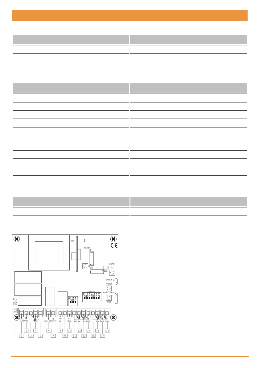
1 / 2 Power supply 230Vac
3 / 4 Motor
5 Common motor
6 Auxiliary contact outlet
7 Auxiliary contact outlet
8 24Vac outlet
9 24Vac common outlet
10 24Vac autotest outlet ( TEST
SEC.)
11 Common start/stop and
security contacts
12 Security close contact (NC)
(SEC.CL.)
jcmtechnologies
3
13 Security open
contact (NC)
(SEC.OP.)
14 Start/stop button
(NO) (START)
15 Common push-
buttons
16 Stop button (NC)
(STOP)
17 Close button
(NO) (CLOSE)
18 Open button
(NO) (OPEN)

GENERAL DESCRIPTION
Control panel with built-in receiver and Radioband system f or axis c entre motors and automatisms for roller doors and shut-
ters. For three types of operations: automatic operations, semi-automatic operations and “deadman” operations (with radio
buttons). Allows for 15 transmitters to be memorised.
It is fitted with one inlet for the s tart/stop button and one for the two security edges and an output for photocell supply and one
for autotesting.
Programming the independent openingand closing times.
INSTALLATION AND CONNECTIONS
Fit the rear of the box to the wall using the rawlplugs and screws supplied. Pass t he cables through the bottom of the equip-
ment. Connect the power supply cables to the terminals on the printed circuit, following the indications engraved on the board.
Fit the front of the equipment to the rear using the screws supplied.
If the door does not open when the button is first pushed, invert the motor cables.
OPERATION
Start (START)
Stop (STOP)
OPEN
CLOSE
Security contact ( SEC.CL. /
SEC.OP.)
Auto-test outlet (TEST SEC.) 24 Vac outlet for auto-test of security parts.
24 Vac outlet
Auxiliary contact outlet Voltage-free contact to activate garage light, for example (maximum 10 A).
Safety edge
Contact normally open to open and close. The first press opens, the second
press stops (until the limit switch) and the third closes.
Contact normally closed. This detains the operation on standby for a new
order. Where not used, turn option 3 ( STOP) on the input switch to ON.
Contact normally open to open. If it is pressed while the door isclosing, it will
stop and open.
Contact normally open to close. If it ispressed while the door isclosing, it will
not be triggered.
Contact normally closed, photocellor magnetic detector type. Thisacts on
opening and closing, causing stoppage and inversion. Where not used, turn
option 1 or 2 on the input switch to ON.
To power any equipment at a voltage of 24 Vac with a maximum consumption of 100 mA.
On opening it causesstoppage and inversion of 2 s and on closure causes
stoppage and complete movement inversion.
Power: When the panel is switched on, the green pilot light indicates the correct power
supply to the equipment.
jcmtechnologies
4

1- Automatic operation
Using buttons, radio transmitters or radio buttons
Turn option 6 (AUTOCLOSE) on the option sw itch to ON.
Connect a NO st art/stop butt on on the terminals marked START. This button c arries out two functions: start and stop.
Depending on the version, it is possible t o use the terminals indicated as OPEN, CLOSE and STOP to make the movement.
If option 5 on the option swit ch is turned to ON, the motor st arts when t he button is pressed for the f irst time. It st ops when
pressed for the second time and it closes when pressed for t he third time if the end of the openingtime is complete. If not, it
continues to open.
2- Semi-automatic operation (default option)
Using buttons, radio transmitters or radio buttons
Turn option 6 (AUTOCLOSE) on the option sw itch to OFF.
Connect a NO st art/stop butt on on the terminals marked START. This button c arries out two functions: start and stop.
Depending on the version, it is possible t o use the terminals indicated as OPEN, CLOSE and STOP to make the movement.
If option 5 on the option swit ch is turned to ON, the motor st arts when t he button is pressed for the f irst time. It st ops when
pressed for the second time and it closes when pressed for t he third time if the end of the openingtime is complete. If not, it
continues to open.
3- Open/close dead man operating
Turn options 1 and 2 on the option switch to ON.
Using pushbuttons
Connect two pushbuttons. One on the OPEN terminal that will operate as a deadman butt on in opening, and the other on the
CLOSE terminal t hat will operate as a dead man button in closing.
By radio
Radio dead-man operations are only possible using the radio button or t he radio key switch, previously programmed on the
equipment. I t is not possible wit h transmitters.
4- Semi-automatic operating in opening and dead man operating in closing
Turn option 2 on the option switch to ON.
Using pushbuttons
Connect two pushbuttons. One on the OPEN or START terminal that will operate as a start button in opening, and the other on
the CLOSE terminal that w ill operate as a dead man button in closing.
By radio
Radio dead-man operations are only possible using the radio button or t he radio key switch, previously programmed on the
equipment. I t is not possible wit h transmitters.
In automatic or semi-automatic mode, dead-man operations can be forced using the OPEN,
CLOSE and/or radio buttons. During this operating mode, the panel will take no enabled secur-
ities into account.
jcmtechnologies
5

Time programming
The door must be completely closed before starting time programming.
Press the PANEL PROG button for 1 second to enter programming. The red PRG pilot light will come on and t he equipment will
emit an acoust ic signal.
Use the START or T EST butt on to programme t he run.
When START/TEST is pressed for t he first time, t he door will act as follows: Opens slightly, closes to the lower st op, opens to
the upper stop and st ops moving. When START/TEST is pressed for the second time, the panel memorizes the automatic
standby time, closes to the lower stop, stops and exits the programming mode (the red pilot light goes out). The opening and
closing t ime will now have been programmed.
Option switch
ON position OFF position (default position)
1- DM OP
2- DM CL
3- AUTO-TEST OP
4- AUTO-TEST CL
5- OPEN-STOPOPEN
6- AUTO-CLOSE Automatic closure Does not close automatically
7- FLASH
Dead-man operation: The START button serves as
the Open button
Dead-man operation: The TEST button on the board
serves as the Close button
This carries out the auto-test for the security open
contact
This carries out the autot-est for the security open
contact
The panel always opens until the end of the opening
time
Courtesylight acts as the signal with a 1.5 sec. prewarning during door movement
Semi-automatic operation
Semi-automatic operation
No auto-test carried out
No auto-test carried out
Alternative operation: openstop-close-stop
Courtesylight acts as the garage light for 60 sec. after door
movement
Input switch
Option No. Lower position – OFF Upper position – ON (default option)
1- SEC.CL Security Close contact connected Security Close contact not connected
2- SEC.OP Security Open contact connected SecurityOpen contact not connected
3 STOP Stop button connected Stop button not connected
Light indicators
POWER Indicates power
PROG Indicates progr amming
SAFETY FiXED Indicates failure of safety or Radioband element autotest
SAFETY BLINKING Indicates security edge inhibiting
Lock and end of run detection
The panel includes a function that automatically detects the end of the run or detects when the motor is mechanically blocked,
stopping movement in both cases.
In programming mode, this circuit saves on users having to press START/TEST.
In operatingmode, the panel protect s the motor in the event of becoming blocked.
The f unction does not replace sensitive edge protection.
jcmtechnologies
6

Safety edge inhibition
The panel includes a function that automatically inhibits the s afety edge f or the last 4cm of t he run.
Continuous floor and ceiling level correction
The panel includes a continuous floor and ceiling level detection and correction sys tem that operates in operating mode
whenever the door has been fully opened or closed from its end positions.
Receiver operation
Upon receiving a code, the equipment checks whether it is in its memory, activating the correspondingrelay.
Manual programming
Normal programming
Press the PANEL PROG button for 1 sec. The programming pilot light will come on and t he equipment will emit an acoustic sig-
nal. The equipment will enter normal programming. Send the code and the channel to be programmed by pressing the trans-
mitter.
Every time a t ransmitter is programmed, t he equipment will issue an acoustic signal for 0.5 sec. After 10 seconds without pro-
gramming or by pressing the programmingbutton, the equipment will exit programming mode, issuing t wo 1 sec. acoustic sig-
nals. If, on programming a t ransmitter, t he equipment memory is full, it will issue seven 0.5 sec. acoustic signals and exit
programming.
By pressing the transmitter channel, opening and closure is activated in automatic operating mode.
Open/close programming
In normal programming, press the PANEL PROG button againand keep it pressed down until the red pilot light f lashes and the
equipment emits a short acoustic signal. The equipment will now have entered open/close programming. Press the required
channel of the transmitt er to be programmed. The first channel opens and the second closes (3rd channel opens and 4th chan-
nel closes).
Every time a t ransmitter is programmed, t he equipment will issue an acoustic signal for 0.5 sec. After 10 seconds without pro-
gramming or by pressing the programmingbutton, the equipment will exit programming mode, issuing t wo 1 sec. acoustic sig-
nals. If, on programming a t ransmitter, t he equipment memory is full, it will issue seven 0.5 sec. acoustic signals and exit
programming.
Each transmitter channel can be configured independently on the equipment, occupying only
one memory position.
Programming by radio
To enter programming, press t he first two buttons on a t ransmitter that has already been registered on the equipment. The
equipment will issue a 1 sec. acoustic signal. On pressing any button on the new transmitter, the equipment will issue another
1 sec. acoustic signal to indicate that it has been memorised. The new transmitt er will maintain t he same channel con-
figuration as the transmitter registered.
After 10 seconds wit hout programming or by quickly pressing t he programming button or pressing the first t wo transmit ter but-
tons, the equipment will exit programming mode, issuing two 1 s ec. acoustic signals.
jcmtechnologies
7

CODE CANCELLATION (TOTAL RESET)
In programming mode, the programming button is held down and the “MR” reset jumper is bridged for 3 secs. T he equipment
will issue 10 short acoustic warning s ignals followed by others at a faster pace to indicate that the operationhas been s uc-
cessf ul. The equipment is now in programming mode. The pilot programming light will also follow the acoustic indications by
flashing.
After 10 seconds wit hout programming or quickly pressing t he programming button, t he equipment will exit programming
mode, issuing two 1 sec. acoustic signals.
RADIOBAND/RC-RCS OPERATIONS
Use the PROG.RB. programming button to programme the safety edges. Follow the RADIOBAND system inst ructions.
Regulatory Data
EU Declaration of Conformity
JCM Technologies hereby declares t hat the product EASY-ROLLcomplies with the relevant fundamental requirements of the
RED Directive 2014/53/EU, as well as with the Machine Directive 2006/42/EC whenever its usage is foreseen; and with t he
2011/65/EU RoHS Directive.
See website www.jcm-tech.com/ en/declarations/
JCM TECHNOLOGIES, SA
C/Costa d’en Paratge, 6 B
08500VIC (BARCELONA)
SPAIN
UM_3201251_EASY-ROLL_EN_Rev01
jcmtechnologies
8
 Loading...