


jcmtechnologies
instruction manual
ACCESS-5K
ACCESS CONTROL UNIT
EN

ACCESS-5K
Contents
Introduction 3
General description 3
Installation 4
Fixing 4
Wiring 5
Power supply + relays 5
Proximity readers 6
Configuration 7
Verification 8
LED Indicators 8
Maintenance 9
Firmware update 9
Cell battery replacement for time/date loss 9
Technical Data 10
Electrical parameters 10
Physical parameters 10
Radiofrequency parameters 10
Solving problems 11
FAQs 11
Safety instructions 13
Use of the system 13
EC Declaration of conformity 13
2 - jcmtechnologies
ACCESS-5K
Introduction
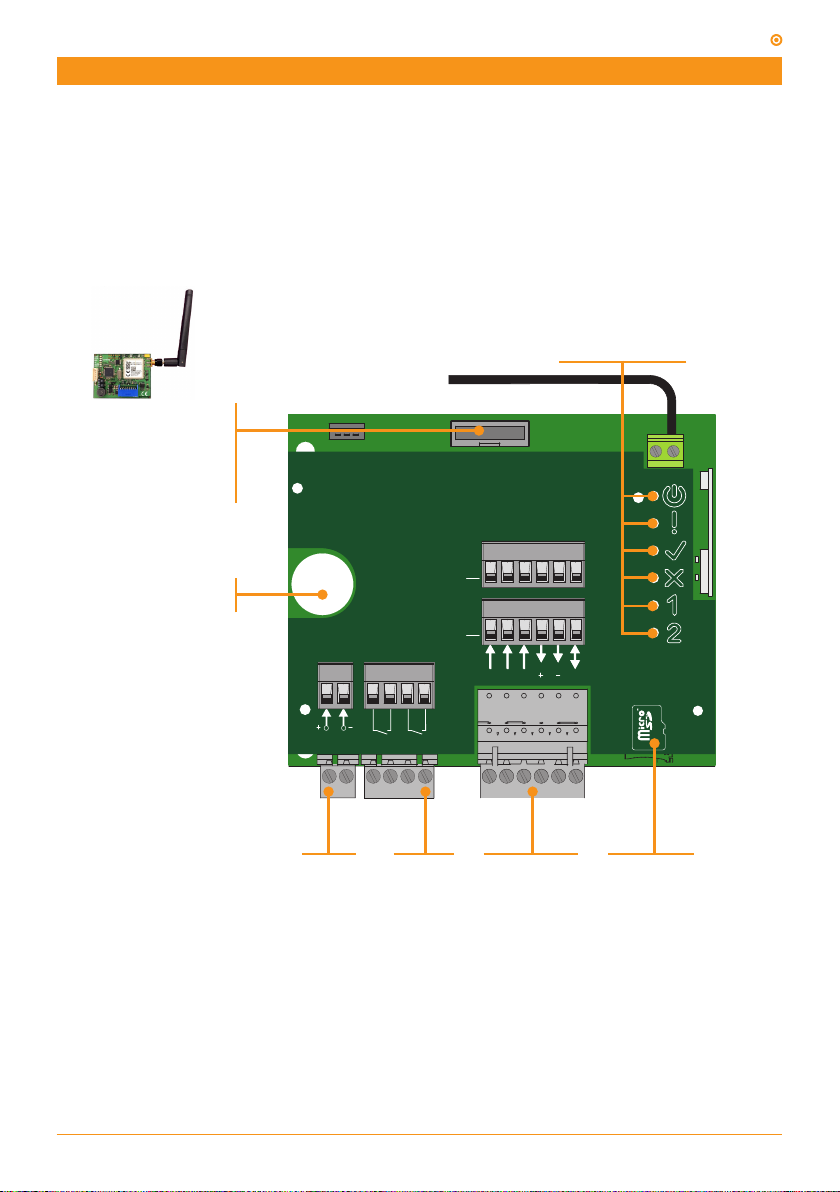
General description
The ACCESS-5K is an autonomous access control unit with time scheduling for small installations up
to 2 doors.
User management is only via Soft Assistant, it is secured against transmitter copies.
OPERATION LEDS
COMMUNICATIONS
CARD CONNECTOR
Optionally, if a GSM-CARD
is connected, the
ACCESS-5K can be remote
managed in real time.
COMMS. CARD
COMMS. CARD
ANT
ANT
Button cell CR2032
Memorises data and time
12/24V
R1 R2
ac/dc
POWER
SUPPLY
OUPUT
RELAYS
(R1/R2)
It completes the ACCESS family with advanced features:
• 5000 users and events
• Scheduling for groups and relays
• 12/24 Vac/dc power supply
• 2 independent Bus L / Wiegand26 inputs
• Improved events management
• Firmware update
3 - jcmtechnologies
RD2
RD1
D0
D1
LED
PROXIMITY
READERS
RD1/RD2
12Vdc
L
MEMORY
SLOT
MICRO SD
ACCESS-5K
ANT
COMMS. CARD
ANT
COMMS. CARD
R1 R2
LED
D0
12Vdc
L
D1
RD1
RD2
Installation
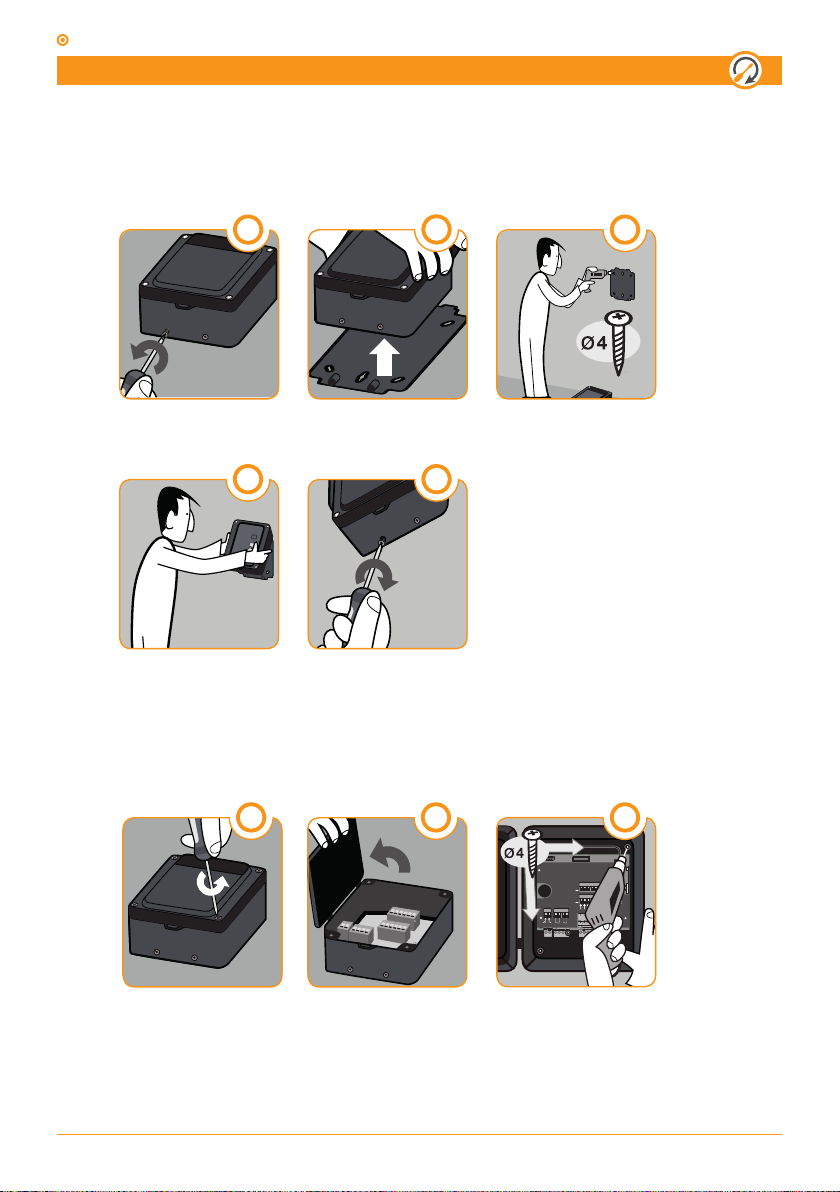
Fixing
Installation with support
UNSCREW
HANG DEVICE
Installation without support
1
REMOVE SUPPORT
4
2
3
DRILL
5
SCREW
UNSCREW
OPEN TOP COVER
4 - jcmtechnologies
21
3
DRILL
Installation
ANT
COMMS. CARD
ANT
COMMS. CARD
R1 R2
LED
D0
12Vdc
L
D1
RD1
RD2
ANT
COMMS. CARD
ANT
COMMS. CARD
RD2
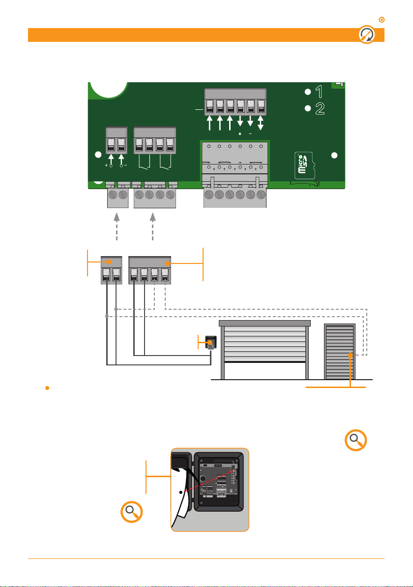
Wiring
Power supply and relays
RD1
LED
ACCESS-5K
12Vdc
D0
D1
L
12/24V
ac/dc
12/24
POWER SUPPLY
Vac/dc
Connect the power
supply cables
Example of installation in control panel.
Check the power supply led
is lighted when power
is turned on
R1 R2
POWER
R1 R2
CONTROL
PANEL
RELAYS
Connect the R1/R2 relay outputs (Normally
Open Contact) to the existing elements of
the installation
ELECTROLOCK
Check power supply
value for electrolock
5 - jcmtechnologies
ACCESS-5K
ANT
COMMS. CARD
ANT
COMMS. CARD
RD2
Installation
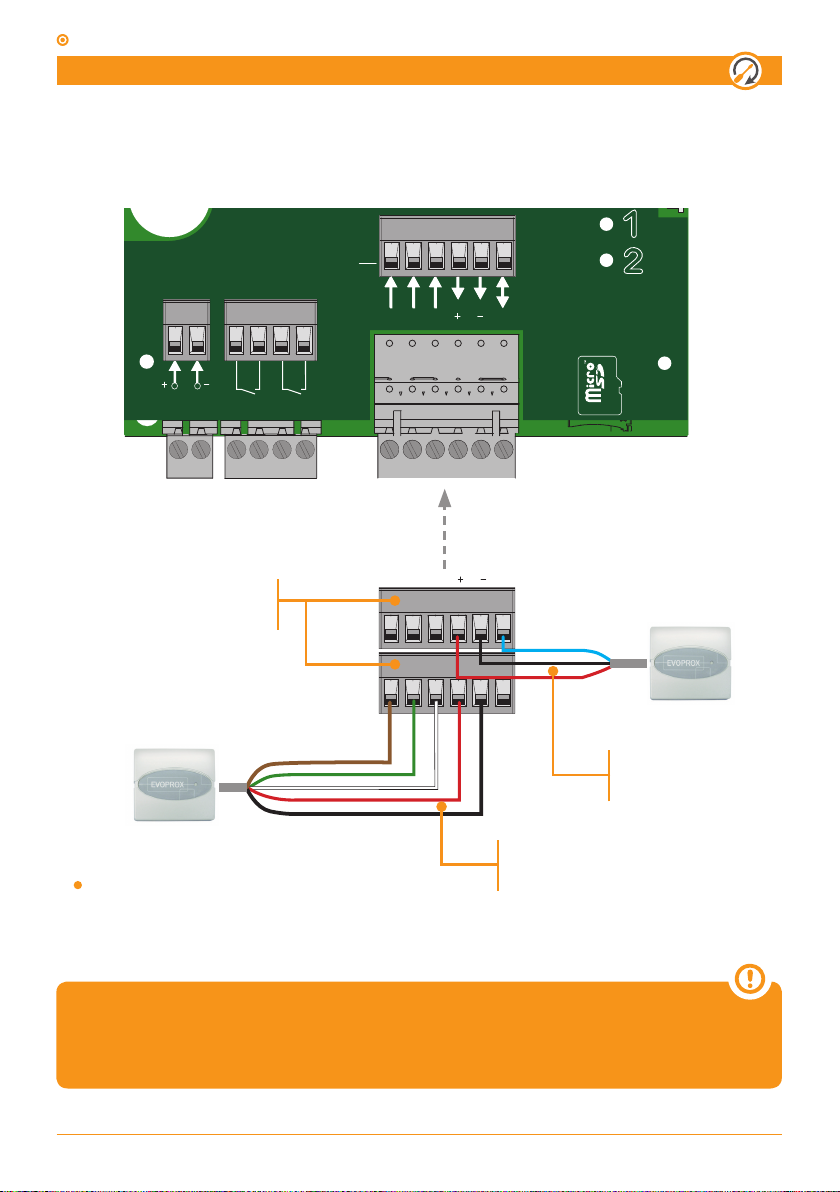
Wiring
Proximity readers
RD1
LED
12Vdc
D0
D1
L
12/24V
ac/dc
R1 R2
PROXIMITY READERS
Connect the desired readers to the
Example of installation in EVOPROX readers.
RD1/RD2 connectors
LED
RD1 RD2
12Vdc
L
D0
D1
BUS L
Channel is defined in
EVOPROX configuration
WIEGAND26
Channel 1 for RD1 reader
Channel 2 for RD2 reader
See the EVOPROX user manual for protocol and channel
configuration.
6 - jcmtechnologies
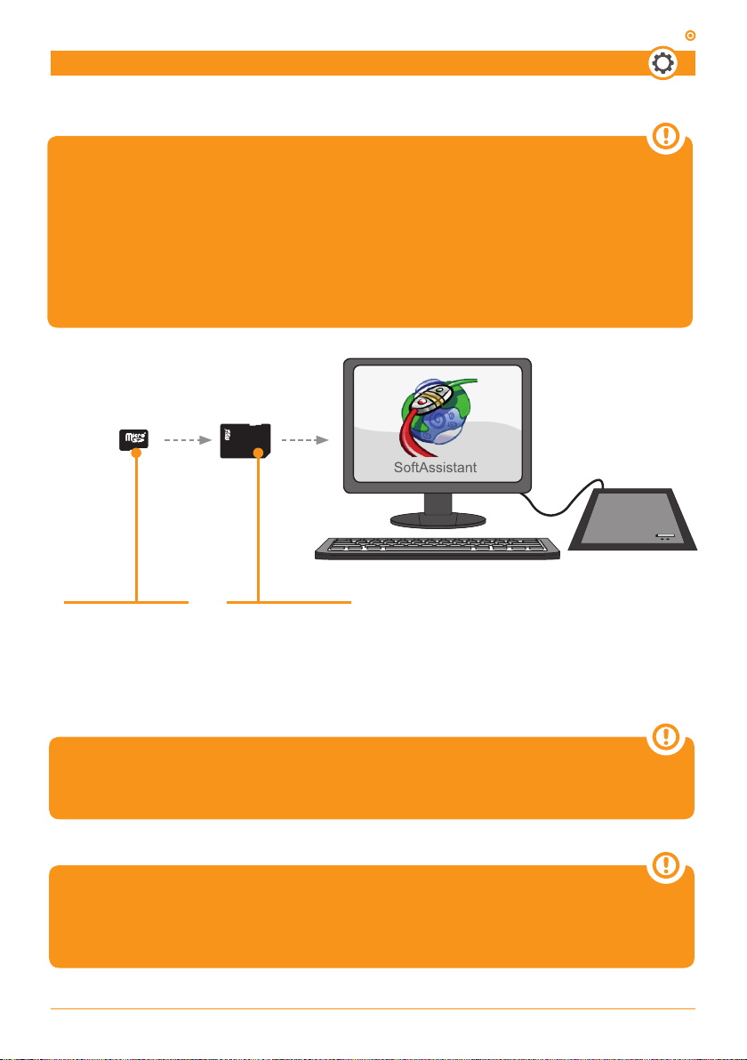
Configuration
This device can be only configured by the software
SoftAssitant.
Check its user manual and the ACCESS-5K specific annex for
details of creating an installation, adding devices, creating user
groups etc...
ACCESS-5K
MICRO SD CARD
Insert into the computer
and configure the system
using SoftAssistant
SD CARD ADAPTER
Use the SD adapter if
necessary
Keep the plastic cover of micro SD memory in a safe place as it
contains the label with the data for remote management.
For more information, visit:
www.jcm-tech.com/en/MAESTRO-PROGMAN-ASSISTANT/
7 - jcmtechnologies

ACCESS-5K
Verification
LED Indicators
WARNING (only A5K+)
Anti- passback input A activation
2 Flashes
Anti- passback input B activation
3 Flashes
Radio programming trial
4 Flashes
Anti-panic activation
Continous flashing
Tamper input activation
1 Flash
POWER SUPPLY
ANT
ANT
OK
1 Flash
Access garanted
Continous flashing
Reading memoy
ERROR
1 Flash
Forbiden access
2 Flashes
Out-of-schedule access
3 Flashes
Anti-passback violation
(only A5K+)
4 Flashes
Firmware update needed
hardware reset
5 Flashes
Transmitters code file not found
Continous flashing
No memory or bad memory format
MEMORY
ERROR
Continous flashing
Wrong customer
code
R1 ACTIVATED
R2 ACTIVATED
8 - jcmtechnologies

Maintenance
Firmware update
Steps to update the firmware in the ACCESS-5K:
• Insert the SD memory in your computer.
• COPY FILE ACCESS5K_AABBCCDD_bin.a5k (AABBCCDD = version) to the uSD memory.
• RENAME FILE copied in the SD to bin.a5k.
• Extract the SD memory from the computer.
• Power off your ACCESS-5K.
• Insert the SD memory in your ACCESS-5K.
• Power on your ACCESS-5K.
• If the OK led flashes fast, slowly and then fast once again. Then:
- The update has finished properly.
- The bin.a5k file has been deleted from SD memory.
• If the ERROR led keeps flashing slowly, an error has occurred:
- Check the file in the SD memory.
ACCESS-5K
- Delete the firmware file manually in order to allow the device to boot normally.
You can also check the current APP version in generated
A5KInfo.txt file in SD memory.
Replacement of the cell battery
In case the ACCESS-5K events lose the date, the button cell battery CR2032 must be changed.
9 - jcmtechnologies

ACCESS-5K
Technical Data
Electrical parameters
Power Supply 12 / 24V dc/ac
Standby / operating consumption <50 mA / 100 mA
Maximum power consumption 5W
Relay power (R1 / R2) 3A
Physical parameters
Operating temperature -20ºC … +55ºC
Size 180 x 150 x 85 mm
IP Rating IP65
Radiofrequency parameters
Motion Frequency 868 MHz
Motion Codification High-security rolling-code
10 - jcmtechnologies

Solving problems
FAQs
Q: How many users can Access 5k unit handle?
A: Up to 5000 users.
Q: How many codes can be added manually?
A: Codes cannot be added manually, they can only be added using SoftAssistant.
Q: Can the unit be blocked so that no one can delete or program more transmitters?
A: It is not necessary to block the unit as the codes can only be managed with the SoftAssistant.
Q: Can any SoftAssistant read the conguration of my unit?
A: ACCESS-5K can be protected through the customer code and the password.
Q: How can the events be read?
A: Connecting the SD card at the computer and opening the events le through SoftAssistant
Q: Can we power the unit at 230 V?
A: No, we can only supply low voltage, 12/24 Vac / dc.
Q: How many relay outputs does the unit have?
A: It has 2 relay outputs.
Q: Are the relays potential free?
A: Yes, also the relays can be used to switch power to an electric lock, for example.
Q: Which sort of readers can be connected?
A: It has 2 relays outputs.
Q: The relays are potential free?
A: There can be connected readers with Bus-L and Wiegand 26 protocol.
Q: How can I know there is an error if the door does not open?
A: A LED indicates the error. Identied by the number of flashes.
ACCESS-5K
11 - jcmtechnologies

ACCESS-5K
Safety instructions
Disconnect the power supply whenever you proceed to the installation
or repair of the control panel.
In accordance with the European low voltage directive, you are informed of the following requirements:
• For permanently connected equipment, an easily accessible connec tion device must be incorporated into the cabling.
• This system must only be installed by a qualified person that has
experience with automatic doors/gates and knowledge of the relevant
EU standards.
• The instructions for use of this equipment must always remain in the
possession of the user.
Use of the system
This equipment is designed for applications where pedestrian doors
installed on garage doors. It is not guaranteed for directly activating
equipment other than that specified.
The manufacturer reserves the right to change the specification of the
equipment without prior warning.
EC Declaration of conformity
JCM TECHNOLOGIES, S.A. declares herewith that the product ACCESS-5K complies with the requirements of the 1999/5/ CEE R&TTE Directive, and complies with the fundamental requirements of the
2004/108/EC Directive on electromagnetic compatibility and 2006/95/
EC on low voltage, insofar as the product is used correctly.
See web www.jcm-tech.com/en/declarations
UM_3200401_EN_Rev00.pdf
12 - jcmtechnologies
 Loading...