


Support: http://www.jcmglobal.com/en/contact/default.aspx Web-Site: http://www.jcmglobal.com
DT-300™ Series
Download Tool
Operator Integration Guide
Revision 1, April 1, 2013
P/N 960-000167R_Rev. 1 {EDP #214645}
Issue #4033-IGE-01-01
© 2013, Japan CashMachine Co., Limited

DT-300™ Series Download Tool Operator Integration Guide
or
or or
or
CE Warning
This is a class A product. In a domestic environment this product may cause radio interference in which case the user may be
required to take adequate measures.
FCC WARNING
Changes or modifications not expressly approved by the party responsible for compliance could void the user’s authority to
operate the equipment.
FCC NOTICE
This equipment complies with Part 15 of FCC Rules. Operation is subject to the following two conditions: (1) this device may not
cause interference, and (2) this device must accept any interference received, including interference that may cause undesired
operation.
This equipment generates, uses and can radiate radio frequency energy and, if not installed and used in accordance with the
instructions, may cause harmful interference to radio communications. Operation of this equipment in a residential area is likely to
cause harmful interference in which case the user will be required to correct the interference at his own expense.
IC NOTICE
This class A digital apparatus complies with Canadian ICES-003.
Cet appareil numerique de la classe A est conforme a la norme NMB-003 du Canada.
Issue #4033-IGE-01-01
REVISION HISTORY
Rev №. Date Reason for Update Comment
A 10/09/12
1 4/1/13
Initial Document
Display change
International Compliance
• RoHS Directives
• CE Mark
• FCC Directives See below.
Copyright © 2013 By Japan CashMachine Co., Limited
This product document (hereinafter referred to as “Manual”) is fully covered by legal Copyrights owned by the Japan
Cash Machine, Co., Ltd., (hereinafter referred to as “JCM”) under Japanese laws and foreign countries. This Manual
contains many copyrighted, patented or properly registered equipment items manufactured by JCM, that are prohibited
and illegal to duplicate, replicate, or copy in whole, or in part, without the express authorization by JCM with the following
exceptions:
1. When an authorized JCM agency or distributor duplicates the Manual for sales promotion and/or service
maintenance of the product, or technical service personnel education as required; and
2. When an end user duplicates the Manual to maintain operation of the product or operate the product in general.
JCM retains all rights to amend, alter, change or delete any portion of this Manual in whole, or in part, or add items
thereto without notice regarding the product or its related products.
JCM is a registered trademark of Japan CashMachine Co, Limited. All other product names mentioned herein may be
registered trademarks or trademarks of their respective companies. Furthermore,
in each case throughout this publication.
™, ® and © are not always mentioned

i
DT-300™ Series
Operator Integration Guide
Table of Contents
Page
TOC
1 GENERAL INFORMATION......................................................................................1
Description.......................................................................................................................... 1
DT-300 Device....................................................................................................................
2 COMPONENT NAMES ............................................................................................2
3 PRIMARY FEATURES.............................................................................................2
4 PRECAUTIONS........................................................................................................
User Cautions ................................................................................................................................. 3
5 SPECIFICATIONS....................................................................................................4
Technical Specifications...................................................................................................... 4
Environmental Specifications .............................................................................................. 4
Electrical Specifications ...................................................................................................... 4
Structural Specifications...................................................................................................... 4
6 INSTALLATION .......................................................................................................5
Battery Installation .............................................................................................................. 5
SD Card Installation............................................................................................................5
Installation to a PC or a Card Reader ............................................................................................. 5
SD Card Installation Into a DT-300 ...............................................................................................
DIP Switch Setting ..............................................................................................................6
Functions ..........................................................................................................................
Bootloader....................................................................................................................................... 6
MainApplication (Normal Mode).......
Boot Mode........................................................................................................................... 6
Authentication ...................................................................................................................
USB Cable Connection....................................................................................................... 6
Operation Procedures
(MainApplication) ................................................................................................................
Firmware Update Function.............................................................................................................. 6
Statistics Function...............................................................................................................
Reviewing an Acceptance Log (Total)........................................................................................... 7
Display the Acceptance Log .......................................................................................................
Enabling a Denomination Function............................................................................................... 8
Error Message Function ................
Version Check Function...........................................................................................................
Maintenance Function .............................................................................................................
Acceptance Log Function (Limited) .....................
Display the Number of the Banknote Acceptance Log ............................................................... 10
Language Function ...............................................................................................................
Operation Procedures
(Bootloader) ......................................................................................................................
DT-300 Firmware Update.............................................................................................................. 11
DT-300 EEPROM Update.............................................................................................................
Power Management.......................................................................................................... 12
Monitoring Battery Charge Level .................................................................................................. 12
Battery Condition Display........................................................................................................
Sleep Mode......................................................................................................................
Backlight Control.................................................................................................................
Software Data File .................
Received Log File ...............................................................................................................
Firmware File ...................................................................................................................
............................................................................................... 6
............................................................................................... 9
....................................................................... 10
............. 12
....................................................................................................... 13
............. 13
.. 5
.. 6
.. 6
............ 7
.. 8
..... 9
..... 9
...... 11
.11
11
...... 12
.......... 13
.......... 13
1
3
6
P/N 960-000167R_Rev. 1 {EDP #214645} © 2013, Japan CashMachine Co., Limited

ii
DT-300™ Series Operator Integration Guide
Table of Contents
Page
EEPROM Data File........................................................................................................................13
7 CONNECTOR PIN ASSIGNMENTS...................................................................... 13
8 UNIT DIMENSIONS ...............................................................................................
DT-300 Entire Unit Outside Dimensions........................................................................................14
9 COMPATIBILITY ................................................................................................... 14
10 ERROR CODES .................................................................................................... 15
Bootloader Error Codes.................................................................................................................15
MainApplication Error Codes.....................................................................................................
11 INTERNATIONAL COMPLIANCE......................................................................... 18
12 TECHNICAL CONTACT INFORMATION ............................................................. 19
America .........................................................................................................................................19
JCM American.............................................................................................................................19
Europe, Africa, Russia & Middle East .......................
JCM Europe GmbH.................................................................................................................
UK & Ireland .....................................................................................................................
JCM Europe (UK Office)..........................................................................................................
Asia & Oceania....................................................................................................................
JCM Gold (HK) Ltd. .....................................................................................................................19
Japan Cash Machine Co, Limited (HQ)...................
....................................................................19
.............19
....................................................................19
13 INDEX .................................................................................................................... 21
14
....15
....19
....19
..........19
P/N 960-000167R_Rev. 1 {EDP #214645} © 2013, Japan CashMachine Co., Limited

iii
DT-300™ Series
Operator Integration Guide
List of Figures
Page
LOF
Figure 1 DT-300 BlueWaveDX Device........................................................................1
Figure 2 DT-300 Component Names..........................................................................
Figure 3 Precautionary Symbols.................................................................................3
Figure 4 Type AAA Battery Installation
Figure 5 SD Card Insertion (PC or Card Reader) .......................................................
Figure 6 Model Name Creation...................................................................................5
Figure 7 Model Folder Creation ..................................................................................
Figure 8 SD Card Insertion (DT-300)
Figure 9 Cable Connection .........................................................................................6
Figure 10 SD Card Confirmation Screen 1 ...................................................................6
Figure 11 Function Selection Screen 1 .........................................................................6
Figure 12 Select the Download File ..............................................................................7
Figure 13 Download Waiting Screen.............................................................................7
Figure 14 Flash ROM Erase Standby Screen...............................................................7
Figure 15 Software Downloading Screen......................................................................7
Figure 16 Software Download Verifying Screen ...........................................................7
Figure 17 Software Download Complete Screen ..........................................................7
Figure 18 SD Card Confirmation Screen 2 ...................................................................7
Figure 19 Function Selection Screen 2 .........................................................................7
Figure 20 Acceptance Log Standby Screen 1...............................................................7
Figure 21 Acceptance Log Reading Screen .................................................................8
Figure 22 Log Read Complete Screen..........................................................................
Figure 23 SD Card Confirmation Screen 3 ...................................................................8
Figure 24 Function Selection Screen 3 .........................................................................8
Figure 25 Standby Screen 1 .........................................................................................8
Figure 26 Denomination Table Screen .........................................................................
Figure 27 SD Card Confirmation Scr
Figure 28 Function Selection Screen 4 .........................................................................9
Figure 29 Standby Screen 2 .........................................................................................
Figure 30 Active Error Code Indication Screen.............................................................9
Figure 31 SD Card Confirmation Scr
Figure 32 Function Selection Screen 5
Figure 33 Standby Screen 3 .........................................................................................9
Figure 34 Version, CRC & Serial Num
Figure 35 SD Card Confirmation Scr
.......................................................................5
..........................................................................5
een 4 ...................................................................9
een 5 ...................................................................9
.........................................................................9
ber Screen ........................................................9
een 6 ...................................................................9
2
5
5
8
8
9
P/N 960-000167R_Rev. 1 {EDP #214645} © 2013, Japan CashMachine Co., Limited

iv
DT-300™ Series Operator Integration Guide
List of Figures
Page
Figure 36 Function Selection Screen 6 ........................................................................ 9
Figure 37 Standby Screen 4......................................................................................... 9
Figure 38 Maintenance Request Screen.................................................................... 10
Figure 39 Maintenance Non-Request Screen ............................................................ 10
Figure 40 SD Card Confirmation Screen 7................................................................. 10
Figure 41 Function Selection Screen 7 ...................................................................... 10
Figure 42 Standby Screen 5....................................................................................... 10
Figure 43 Acceptance Log Reading Screen............................................................... 10
Figure 44 Log Read Complete Screen ....................................................................... 10
Figure 45 SD Card Confirmation Screen 8................................................................. 11
Figure 46 Function Selection Screen 8 ...................................................................... 11
Figure 47 Language Selection Screen ....................................................................... 11
Figure 48 Firmware Update Confirmation Screen ...................................................... 11
Figure 49 Firmware Update Progress Bar.................................................................. 11
Figure 50 Firmware Update Success Screen............................................................. 11
Figure 51 EEPROM Update Confirmation Screen ..................................................... 11
Figure 52 EEPROM Update Progress Bar ................................................................. 12
Figure 53 EEPROM Update Success Screen ............................................................ 12
Figure 54 Sleep Mode Screen.................................................................................... 12
Figure 55 DT-300 Download Tool Outside Dimensions ............................................. 14
P/N 960-000167R_Rev. 1 {EDP #214645} © 2013, Japan CashMachine Co., Limited

v
DT-300™ Series
Operator Integration Guide
List of Tables
Page
LOT
Table 1 DT-300 Technical Specifications....................................................................4
Table 2 DT-300 Environmental Specifications
Table 3 DT-300 Electrical Specifications.....................................................................4
Table 4 DT-300 Structural Specifications....................................................................
Table 5 Boot Mode Selection ......................................................................................
Table 6 Acceptance Log..............................................................................................8
Table 7 Reading Denomination Table.........................................................................
Table 8 Log Storage Limit .........................................................................................
Table 9 Acceptance Logs Available ..........................................................................10
Table 10 Performance and Battery Condition .............................................................12
Table 11 Battery Condition Indication .........................................................................12
Table 12 Various Sleep Mode Screens.......................................................................12
Table 13 Software Data File Information.....................................................................13
Table 14 Received Log Files.......................................................................................13
Table 15 Existing Firmware File..................................................................................13
Table 16 EEPROM Data File Information ...................................................................13
Table 17 DT-300 USB Type “A” Pin Assignments ......................................................13
Table 18 DT-300 Compatible Validators .....................................................................14
Table 19 Bootloader Error Codes................................................................................15
Table 20 MainApplication Error Codes........................................................................15
............................................................4
10
4
6
8
P/N 960-000167R_Rev. 1 {EDP #214645} © 2013, Japan CashMachine Co., Limited

vi
DT-300™ Series Operator Integration Guide
THIS PAGE INTENTIONALLY LEFT BLANK
P/N 960-000167R_Rev. 1 {EDP #214645} © 2013, Japan CashMachine Co., Limited
1
DT-300™ Series
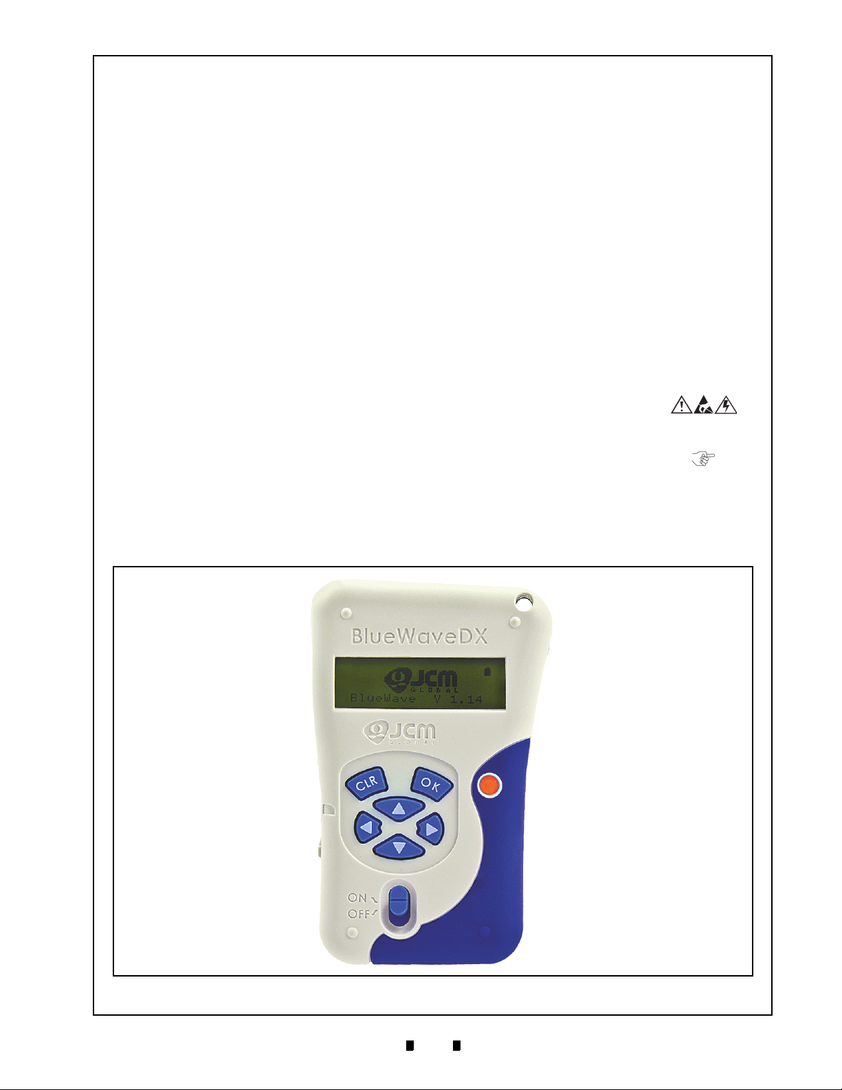
1 GENERAL INFORMATION
DT-300 Device
Figure 1 DT-300 BlueWaveDX Device
Download Tool
Operator Integration Guide
Revision 1
Description
This section provides a general overview of the
DT-300™ “BlueWaveDX” Downl
pictured in Figure 1. This first section is designed
to help the user navigate through this guide with
e and provides the following information:
eas
• DT-300™ Device
• Component Names
• Primary Features
• Precautions
• Specifications
• Installation
• Connector Pin Assignments
• Functions
• Unit Dimensions
• Compatibility
oad Tool Device
• Technical Contact Information.
In order to make operation of this device easier and
make
navigation within this manual simpler, the
following illustrations were used within the text:
• Safety Instructions
observed in order to protect the operators and
equipment, have been written in bold text and
have been given the pictographs:
• S
pecial Notes, which affect the use of the DT-
300™ Device, have been written in italic text
and have been given the pictograph:
teps, requiring the operator to perform
• S
specific actions are given sequential numbers
(1., 2., 3., etc.).
, which need to be
P/N 960-000167R_Rev. 1 {EDP #214645} © 2013, Japan CashMachine Co., Limited

2
DT-300™ Series Download Tool Operator Integration Guide
Figure 2 DT-300 Component Names
A. USB Connector Type A (Host)
B. LCD (Monochrome)
C. OK Button
D. CLR Button
E. Power LED (Red)
F. Direction Key Button
G. Power Switch
H. SD Card Slot
I. Battery Compartment Cover
J. Power Plug (Option)
K. Magnet
L. Magnet
A
B
C
D
E
F
G
H
I
K
J
L
2 COMPONENT NAMES
Figure 2 illustrates the DT-300™ Functional Component Part Names and Locations.
3 PRIMARY FEATURES
The DT-300™ “BlueWave” Series Download Tool contains the following primary features:
• The DT-300™ is a battery-driven device. The DT-300 transfers the softw
supplied Validator.
• The DT-300™ features an LCD Display. The Bootloade
selection are available by using the LCD Display. The Acceptance Log, Error Messages, Version/CRC/
Serial Number, Maintenance Condition, Enabled Denomination and Language Selection are also
confirmed by the LCD Display.
• Refer to “Operation Procedures (MainApplication)” on page 6 of this Guide for more details.
are data to the power-
r update and the MainApplication function
P/N 960-000167R_Rev. 1 {EDP #214645} © 2013, Japan CashMachine Co., Limited

3
DT-300™ Series Download Tool Operator Integration Guide
Type 1 Type 2 Type 3
Figure 3 Precautionary Symbols
Caution: DO NOT use a new Battery
along with an old Battery together.
Doing so will decrease the life of
both Batteries, or Battery liquid
content seepage may occur.
Caution: Pulling on the USB Cable
alone may damage the cable and
cause a fire, electrical shock or
both. Also do not damage, break,
or redesign the recommended USB
Cable.
Caution: Do NOT touch or pull on
the connecting Cables with wet
hands; this may cause an electrical
shock, equipment damage or both.
4 PRECAUTIONS
The Figure 3 symbols are defined as follows:
1. (Type 1) Do not use any other Cables except the
specified USB Type A Cable.
Type 2) Do not expose the Unit to water. The
2. (
Unit contains several precision electronic devices
that can be damaged if water or any type of
liquid is sprayed or spilled into the Unit.
Type 3) Do not expose the Unit in a dusty
3. (
environment.
U
SER CAUTIONS
1. Do not use or store the DT-300™ at the following locations:
• In direct Sunlight
• In a dusty environment
• Areas likely to be wet or humid
• Vibrating areas
• Near hazardous materials.
2. Do not insert and/or drop foreign objects
such as metals or flammable substances into
the DT-300™ Unit.
3. Use “AAA” Alkaline size Batteries (LR03)
to Power the Unit.
300’s Power OFF before replacing Batteries.
When replacing Batteries, change all four (4)
Batteries and install them in the correct direction.
Be sure to turn the DT-
5. Do not redesign or disassemble the
DT-300™ Device. Disassembly and repair
should only be
performed by a certified JCM
Service Center or a professional technician.
Unauthorized repair, use
by inadequately
trained personnel, or use outside the manufacture’s original intent voids the warranty.
6. Do not strike, drop or throw the DT-300™
Device
. Contact the local JCM distributor
immediately when identified damage or
internal repair conditions exist.
7. When a communication error occurs, turn the
V
alidator’s Power Switch OFF and then turn
it to ON again.
8. Do not touch the SD Card when downloading
data. Be sure to turn th
e DT-300’s Power
Switch OFF before inserting or removing the
SD Card.
9. Be sure that the Cable length connected to
the V
alidator is less than 3m.
10. Using strong pressure or impact on the Function Buttons may damage the Buttons.
11. Do not put recording mediu
m such as magnetic cards or magnetic tapes close to the DT300’
s Magnet portion. The data recorded in
the medium may be damaged or erased.
4. Be sure to turn the
before plugging or unplugging the USB
Cable. Be sure to remove the USB Cable by
firmly gripping on the plug and not on the
USB Cable itself.
P/N 960-000167R_Rev. 1 {EDP #214645} © 2013, Japan CashMachine Co., Limited
DT-300’s Power OFF

4
DT-300™ Series Download Tool Operator Integration Guide
Hydrothermal Condition Table
35ºC(86ºF)/80%RH
45ºC(113ºF)/30%RH
Temperature (ºC)
Humidity (%RH)
Allowable Operating Temperature
and Humidity Range
5 SPECIFICATIONS
Technical Specifications
Table 1 DT-300 Technical Specifications
Compatibility: UBA, iVIZION, VEGA, TBV, iPRO & RC Series Units
Software Download Time (from start to completion):
a) UBA-10 (USB): Approximately 60 seconds (Software Size/1MB)
b) UBA-14 (USB): Approximately 120 seconds (Software Size/2MB)
Processing Speed*:
Switches:
Interface:
Display:
*. Download Time depends on Models and/or files.
†. USB is available for only JCM products’ access.
c) iVIZION (USB): Approximately 70
d) VEGA (USB): Approximately 34 seconds (Software Size/2MB)
e) TBV-100 (USB): Approximately 124 seconds (Software Size/8MB)
f) iPRO (USB): Approximately 70 seconds (Software Size/8MB).
Power Switch, OK Button, CLR Button,
Direction Key Button (UP/DOWN/RIGHT/LEFT)
†
USB
Host Single Channel (USB 2.0, Full Speed)
SD Card (SDHC acceptable)
Monochrome LCD (122x32 dots with back light)
LED (Light-emitting Diodes) (Red)
Environmental Specifications
Table 2 DT
-300 Environmental Specifications
seconds (Software Size/8MB)
Operating Temperature: 5ºC to +45ºC (41ºF to 113ºF)
torage Temperature: -20ºC to +60ºC (-4ºF to 140ºF) (Batteries are exception)
S
Relative Operating Humidity: 30% to 80% RH (non-condensed)
Relative Storage Humidity: 15% to 95% RH (non-condensed)
Visible Light Sensitivity: Avoid Direct Sunlight
Electrical Specifications
Table 3 DT
Supply Voltage: Four (4) AAA/LR03 Size Alkaline Batteries (provided by User)
Current Consumption:
*. 70mA for less then ten (10) minutes while entering Standby.
Standby = 20mA
Downloading = 90mA
-300 Electrical Specifications
*
Structural Specifications
Weight Empty: Approximately 165g (5.82oz) without Batteries and SD Card
side Dimensions: Refer to “Unit Dimensions” on page 14 of this Guide
Out
P/N 960-000167R_Rev. 1 {EDP #214645} © 2013, Japan CashMachine Co., Limited
Table 4 DT-300 Structural Specifications

5
DT-300™ Series Download Tool Operator Integration Guide
Tabs
+
+
a
Figure 4 Type AAA Battery Installation
NOTE: When creating the storage Folder for
each Model, use the SD Card Slot of a PC or an
SD Card Reader.
SD Card
SD Card
SD Card
SD Card
Slot
Reader
Figure 5 SD Card Insertion (PC or Card Reader)
Space
Figure 6 Model Name Creation
NOTE: Up to twenty (20) Folders can be
created on an SD Card.
Figure 7 Model Folder Creation
NOTE: Refer to “Compatibility” on
page 14 for the details regarding each
Model’s setting.
NOTE: Do NOT erase the
“BWDXCARD.INF” Card Information File!
If the Card Information is lost, Card
Reading errors may occur.
NOTE: When removing the SD Card,
follow the User Guide of the PC, or the
SD Card Reader.
SD Card
SD Card Slot
Figure 8 SD Card Insertion (DT-300)
6 INSTALLATION
Battery Installation
Perform the following steps to install Batteries into
the DT-300™ Device:
1. Push the two (2) Tabs of the Battery Cover in the
direction of the Arrow illustrated in Figure 4a and
lift the Cover off of the Device.
2. Install four (4) AAA Batteries into their correct
arized position in the direction illustrated in
pol
Figure 4.
3. Place the Battery Cover back into its original
position, and
place.
listen for it to “Click” back into
SD Card Installation
I
NSTALLATION TO A
Perform the following steps to install the SD Card
into a PC or an SD Card Reader:
1. Insert the SD Card into an SD Card Reader, or an
SD Card Reader Slot of the PC.
PC OR A C
ARD READER
3. Save the Software Data Files (xxxxxxxxx.COM)
for each Model’s Folder. Refer to the “Software
Data File” on page 13 of this Guide for more
details.
SD C
ARD INSTALLATION INTO A
DT-300
Perform the following steps to install/remove the
SD Card into/from a DT-300™ Device:
1. Ensure the DT-300™ Power is OFF.
2. Slide the SD Card into the Unit in the direction
indicated
until it “clicks” in place.
by the Red Arrow shown in Figure 8
2. Create each model Folder in the first layer of the
SD Card. Each
“space” before the word “System”.
P/N 960-000167R_Rev. 1 {EDP #214645} © 2013, Japan CashMachine Co., Limited
Folder Name needs to include a

6
DT-300™ Series Download Tool Operator Integration Guide
NOTE: Do NOT push the SD Card in by
using excessive force!
NOTE: Refer to “Compatibility” on
page 14 of this Guide to select the “B” or
“Mini-B” Connection Terminal.
b
a
NOTE: Validator power must be supplied.
Figure 9 Cable Connection
Figure 10 SD Card Confirmation Screen 1
NOTE: Product specifications (e.g.,
version) may vary from illustrations, and
are subject to change without notice.
Figure 11 Function Selection Screen 1
3. When removing the SD Card from the DT-300™,
push in on the SD Card in the insertion direction
once and then pull the SD Card out of the DT300™ Device.
DIP Switch Setting
DIP Switch Settings are necessary to communicate
with the DT-300™ and a Validator. Refer to “Compatibility” on page 14 of this Guide for proper DIP
Switch Settings related to each Validator Model.
Functions
The following two (2) Functions exist for the DT300™ Device:
B
OOTLOADER
The Bootloader Function contains the following
two (2) Modes:
• “BlueWaveDX Firmware Update Mode” to
u
pgrade the Firmware in the DT-300™ Device
• “BlueWaveDX EEPROM Update Mode” to
update the EE
PROM data within the DT-300™
Device.
M
AINAPPLICATION
(N
ORMAL MODE
)
MainApplication (Normal Mode) contains the
following two (2) Functions:
• “Firmware Update Function” to upgrade the
Firmware within
the Validator
• “Acceptance Log Function” to receive and
play the Acceptance Log.
dis
Boot Mode
When the DT-300™ is initialized, three (3) Modes
will be available. Select one Mode by using the
Direction Key Button to move and select to the
desired Operational Mode (See Tab le 5).
Table 5 B
Mode Direction Key Button
DT-300 Firmware Update Mode UP + DOWN
DT-300 EEPROM Update Mode LEFT + RIGHT
Normal Mode (MainApplication)
oot Mode Selection
N/A (except the other
combinat
ions)
Authentication
When the MainApplication is booting, the DT300™ will authenticate itself with the information
on the SD Card.
2. Connect the USB Cable B or Mini-B terminal to
e Validator’s USB Port (See Figure 9 b).
th
Operation Procedures
(MainApplication)
This portion provides each MainApplication
procedure of the DT-300™ Device Operation.
F
IRMWARE UPDATE FUNCTION
To update the Firmware of the Validator, proceed
as follows:
1. Make sure that the SD Card contains the required
Software Data File (Refer to “Software Data File”
on page 13 of this Guide for details regarding
selection of the correct So
2. Turn the DT-300™ Power Switch ON; an SD
Card check will begin as shown in Figure 10.
3. Select “FIRMWARE UPDATE” Function on the
Function Selection Screen shown in Figure 11,
and press the
Erase process.
OK Key to begin the Firmware
ftware Data File).
USB Cable Connection
Perform the following steps to connect a PowerSupplied Validator to the DT-300™ Device:
1. Connect the USB Cable A Terminal to the DT300™ Unit’s Connector “A” Port (See Figure 9
a).
P/N 960-000167R_Rev. 1 {EDP #214645} © 2013, Japan CashMachine Co., Limited
4. Connect the USB Port of the V
300™ Device using a proper USB Cable.
5. Select the download File desired by pressing the
UP Key or the DOWN Key , and then
alidator to the DT-

7
DT-300™ Series Download Tool Operator Integration Guide
NOTE: The DT-300 screen can display
up to (20) files using the UP or
DOWN key. [The SD card may have
additional storage, but files exceeding
twenty (20) will not display.]
Figure 12 Select the Download File
NOTE: If the connection between the
Validator and the DT-300 fails, or the
Software selected is inappropriate for the
Validator, a Software download will not
begin!
Figure 13 Download Waiting Screen
Figure 14 Flash ROM Erase Standby Screen
NOTE: While downloading Software, NO
Keyboard operations will be accepted!
Figure 15 Software Downloading Screen
Figure 16 Software Download Verifying Screen
Figure 17 Software Download Complete Screen
NOTE: The Acceptance Log File is generated on
the SD Card when it is successfully received
from the Validator. Refer to “Received Log File”
on page 13 of this Guide for details regarding the
Acceptance Log File.
Figure 18 SD Card Confirmation Screen 2
Figure 19 Function Selection Screen 2
Figure 20 Acceptance Log Standby Screen 1
NOTE: While reading the Acceptance
Log, NO Keyboard operations will be
accepted!
press the OK Key to select it (See Figure 12).
[“M:” indicates the “Model
Name” and “V:” indi-
cates the “Version”.]
6. Press the OK Key to begin the Software
download (See Figure 13). Press the
to return to the previous File Selection
Screen.
CLR Key
Download Complete Screen once the OK Key
or the
CLR Key is pressed.
S
TATISTICS FUNCTION
Reviewing an Acceptance Log (Total)
To review the total number Acceptance Log from
the a Validator, proceed as follows:
1. Turn the DT-300™ Power Switch ON, and an SD
Card check will begin (See Figure 18).
2. Select “
Screen, and then press the
it (See Figure 19).
STATISTICS” on the Function Selection
OK Key to accept
7. Ensure that the LCD Display shows the Flash
ROM is in Erase Standby after pressing the
Key
.
The LCD Screen will display a Progress Bar
during the Software download (See Figure 15).
OK
3. Connect the USB Port of the Validator to the DT-
30
0™ Device using a proper USB Cable
(See Figure 20). Once detected, the connection
between the Validator and the DT-300™ will
automatically begin
to receive the Validator’s
Acceptance Log.
4. The LCD Screen will
display a Progress Bar
while the Acceptance Log is being read
(See Figure 21).
After the Software Download is complete
8.
(See Figure 17), the LCD Screen will display the
P/N 960-000167R_Rev. 1 {EDP #214645} © 2013, Japan CashMachine Co., Limited

8
DT-300™ Series Download Tool Operator Integration Guide
Figure 21 Acceptance Log Reading Screen
Figure 22 Log Read Complete Screen
NOTE: The maximum number of Folders allowed
in a DT-300 Device is 20. If more than twenty (20)
Folders are saved in the SD Card Folder, their
functions may not work properly.
Figure 23 SD Card Confirmation Screen 3
Figure 24 Function Selection Screen 3
Figure 25 Standby Screen 1
Figure 26 Denomination Table Screen
NOTE: If the information cannot be
displayed within 3-digits, the rest of the
information can be shown by scrolling
the Display using the UP/DOWN Key.
5. Once reading of the Acceptance Log is complete,
the LCD will display a “
Log Read Complete”
Screen, as shown in Figure 22.
Enabling a Denomination Function
To view/display the Denomination Table, proceed
as follows:
1. Turn the DT-300™ Power Switch ON and an SD
Card check will begin (See Figure 23).
Display the Acceptance Log
To confirm the Acceptance Log, use the UP
Key or the
Press the
DOWN Key to display the Log.
CLR Key to return to the previous
Function Selection Screen. The Acceptance Log
will be read again when re-connecting t
he USB
Cable between the Validator and the DT-300™.
Table 6 listed the available Acceptance Log Displays.
Table 6 Acceptance Log
Screen Description
Model Name
2. Select “
Selection Screen, and then press the
ENABLE DENOMI.” on the Function
OK Key
to select it (See Figure 24).
3. Ensure that the LCD Display shows the Standby
Screen shown in Figure 25.
4. Press the
tion Table Screen (See Figure 26). Press the
OK Key to display the Denomina-
CLR
Key to return to the previous Function Selection Screen.
5. Confirm that the current denomination selected
from
the Denomination Table is correct.
P/N 960-000167R_Rev. 1 {EDP #214645} © 2013, Japan CashMachine Co., Limited
Version
Banknote
Acceptance Rate
Ticket
Acceptance Rate
Denomination,
Country Code, Year
and Acceptance Rate
Table 7 Reading Denomination Table
Code Example
C
D Banknote (5-digit) 100, 200, 500 etc.
E Denomination ($ or €) $ or €
Y Issued Year (2-digit) 02
Country Code (3-digit) EUR, USA etc.

9
DT-300™ Series Download Tool Operator Integration Guide
Figure 27 SD Card Confirmation Screen 4
Figure 28 Function Selection Screen 4
Figure 29 Standby Screen 2
Figure 30 Active Error Code Indication Screen
Figure 31 SD Card Confirmation Screen 5
Figure 32 Function Selection Screen 5
Figure 33 Standby Screen 3
Figure 34 Version, CRC & Serial Number Screen
Figure 35 SD Card Confirmation Screen 6
Figure 36 Function Selection Screen 6
Figure 37 Standby Screen 4
Error Message Function
To receive/display the error condition from the
Validator, proceed as follows:
1. Turn the DT-300™ Power Switch ON, and the
SD Card check will begin (See Figure 27).
3. Ensure that the LCD displays the Standby Screen
shown in Figure 33.
2. Select the “
tion Selection Screen and press the
ERROR MESSAGE” from the Func-
OK Key to
select it (See Figure 28).
3. Make sure that the LCD displays the Standby
Screen shown
4. Press the
in Figure 29.
OK Key to display the Active Error
Code Indication Screen shown in Figure 30. Press
the
CLR Key to return to the previous Func-
tion Selection Screen.
4. Press the
OK Key to display the Version,
CRC and Serial Number Indication Screen
(See Figure 34). Press the
CLR Key to return
to the previous Function Selection Screen.
5. Confirm the Version, CRC and Serial Number.
Press the
OK Key or the CLR Key to
return to the previous Standby Screen.
Maintenance Function
To review/display the Maintenance Condition
information of the Validator, proceed as follows:
1. Turn the DT-300™ Power Switch ON, and the
SD Card check will begin (See Figure 35).
5. Confirm the Active Error Code. Press the
Key or the
CLR Key to return to the previ-
ous Standby Screen.
Version Check Function
To obtain the Version, CRC and Serial Number
from the Validator, proceed as follows:
1. Turn the DT-300™ Power Switch ON, and the
SD Card check will begin (See Figure 31).
2. Select “
Selection Screen and press the
select it (See Figure 32).
P/N 960-000167R_Rev. 1 {EDP #214645} © 2013, Japan CashMachine Co., Limited
VERSION CHECK” from the Function
OK
OK Key to
2. Select “
Selection Screen and press the
MAINTENANCE” from the Function
OK Key to
select it (See Figure 36).
3. Ensure that the LCD displays the
(See Figure 37).
Standby Screen

10
DT-300™ Series Download Tool Operator Integration Guide
Figure 38 Maintenance Request Screen
Figure 39 Maintenance Non-Request Screen
Figure 40 SD Card Confirmation Screen 7
Figure 41 Function Selection Screen 7
Figure 42 Standby Screen 5
NOTE: While reading the Acceptance
Log, NO Keyboard operations will be
accepted!
Figure 43 Acceptance Log Reading Screen
Figure 44 Log Read Complete Screen
4. Press the OK Key to display the Maintenance
Request Indication Screen. Press the
CLR Key
to return to the previous Function Selection
Screen.
5. Confirm the Maintenance Request (See Figure 38
& Figure 39). Press the
OK Key or the CLR
Key to return to the previous Standby Screen.
4. The LCD Screen will display a Progress Bar
during the Acceptance Log reading process as
show
n in Figure 43.
Acceptance Log Function (Limited)
The possible storage amount for Banknote Log
Data is limited for each Validator Type. Tab le 8 lists
each Validator Type’s Log Storage limitation.
Table 8 Log Storage Limit
Model Series Storage Limit
UBA Series 50 Notes
iVIZION Series 1000 Notes
VEGA Series N/A
TBV-100 Series N/A
iPRO Series 50 Notes
To view/display the Banknote Log Data limit of the
V
alidator being tested, proceed as follows:
1. Turn the DT-300™ Power Switch ON, and the
SD Card check will begin (See Figure 40).
2. Select “
Selection Screen and press the
select it (See Figure 41).
ACCEPTANCE LOG” from the Function
OK Key to
5. Once reading of the Acceptanc
e Log is complete,
the LCD will display the Log Read Complete
Screen shown in Figure 44.
Display the Number of the Banknote Acceptance Log
To confirm the amount in the Banknote Acceptance
Log, use the
display the record desired. Press the
to return to the previous Function Select
UP Key or the DOWN Key to
CLR Key
ion Screen.
The Banknote Acceptance Log value will be read
again when re-connecting a USB Cable between
the Validator and the DT-300™ Device.
Table 9 lists the various Acceptance Log Displays
available.
Table 9 Acceptance Logs Available
Screen Description
Record Start Date
3. Connect a proper USB Cable between the Validator and the DT-300™ Device. When the connection is detected, the reload operation will begin
automatically (See Figure 42).
P/N 960-000167R_Rev. 1 {EDP #214645} © 2013, Japan CashMachine Co., Limited
Model Name
Version
Total Number of the
Banknote Insertions

11
DT-300™ Series Download Tool Operator Integration Guide
Figure 45 SD Card Confirmation Screen 8
Figure 46 Function Selection Screen 8
Figure 47 Language Selection Screen
NOTE: The Firmware File should be
newer than the current Firmware Version
presently in the DT-300.
Figure 48 Firmware Update Confirmation Screen
Figure 49 Firmware Update Progress Bar
Figure 50 Firmware Update Success Screen
Figure 51 EEPROM Update Confirmation Screen
Table 9 Acceptance Logs Available (Continued)
Screen Description
Tota l T i cke t
Acceptance Rate
Limited Number of the
Banknote
Acceptance Rate 1
Limited Number of the
Banknote
Acceptance Rate 2
Language Function
To change a Language from English to another
Language, proceed as follows:
1. Turn the DT-300™ Power Switch ON, and the
SD Card check will begin (See Figure 45).
2. Select “
Screen and press the
desired Language from the list available
(See Figure 46).
LANGUAGE” from the Function Selection
OK Key to select the
2. Turn the DT-300™ Power Switch ON while
pressing the
UP Key and the DOWN
Key . The Firmware Update Confirmation
Screen shown in Figure 48 will appear.
3. Press the
OK Key to begin the DT-300™
Firmware update. The LCD Screen will display a
Prog
ress Bar during the Firmware updating pro-
cess as shown in Figure 49.
4. Once the update is comp
display the new “
lete, the LCD Screen will
Bootloader X.XX Succeeded.”
Message (See Figure 50).
3. Select the preferred language; English or Deutsch
(G
erman) as shown in Figure 47 in this example.
Operation Procedures
(Bootloader)
This portion provides each Bootloader procedure of
the DT-300™ Device operation.
DT-300 F
To update the Firmware of the DT-300™, proceed
as follows:
1. Ensure that the SD Card contains the latest Ver-
IRMWARE UPDATE
sion of Firmware (Refer to “Firmware File” on
page 13 of this Guide for details regarding the
proper Firmware File selection).
DT-300 EEPROM U
PDATE
To update the EEPROM Data in the DT-300™
Device, proceed as follows:
1. Ensure that the SD Card contains the EEPROM
Data (Refer to “EEPROM Data File” on page 13
of this Guide for details regarding the EEPROM
Dat
a File).
2. Turn the DT-300™ Power Switch ON while
ng the
pressi
The EEPROM Update Confirmation Screen
shown in Figure 51 will appear.
3. Press the
update. The LCD Screen will display a Progress
Bar
during the EEPROM updating process as
shown in Figure 52.
LEFT Key or the RIGHT Key .
OK Key to begin the EEPROM
P/N 960-000167R_Rev. 1 {EDP #214645} © 2013, Japan CashMachine Co., Limited

12
DT-300™ Series Download Tool Operator Integration Guide
Figure 52 EEPROM Update Progress Bar
Figure 53 EEPROM Update Success Screen
Figure 54 Sleep Mode Screen
4. Once the update is complete, the LCD Screen will
display the “
Bootloader X.XX Succeeded.” mes-
sage (See Figure 53).
Power Management
M
ONITORING BATTERY CHARGE LEVEL
Three (3) Levels of a Battery Charge condition
exist: FULL, LOW and EMPTY. The DT-300™
Unit’s performance is limited by the Battery condition. Table 10 lists the DT-300™ available performance for each Battery condition case.
Table 10 Performance and Battery Condition
Performance Function
LCD Display
LCD Backlight O O X
Key Input O O X
Function Selection O O X
Firmware Update Function O O X
Statistics Function O O X
Enabled Denomination Function O O X
Error Message Function O O X
Version Check Function O O X
Maintenance Function O O X
Acceptance Log Function O O X
Language Function O O X
Bootloader
*. When booting, check the Battery Charge Level. The Bootloader will be
available only when the Battery is FULL. If the Battery condition is
LOW or EMPTY, an error message will appear.
*
Battery Condition
FULL LOW EMPTY
O O O
O X X
Table 11 lists the various Battery Condition Displays.
Table 11 Battery Condition Indication
Display Condition
Battery FULL
Battery LOW
Battery EMPTY
S
LEEP MODE
When no operation has been performed for 10 minutes, the DT-300™ Device will enter Sleep Mode
automatical
(See Figure 54)
ly in order to extend its battery life
. Once Power is re-supplied, or any
Function Key is pressed, the DT
-300™ will again
be ready to begin operation.
When the DT-300™ Device enters Sleep Mode
while downloading the Software or
receiving the
Acceptance Log, the LCD Screen will display the
following messages shown in Tabl e 12.
Table 12 Various Sleep Mode Screens
Screen Description
Download Complete
Download Failed
B
ATTERY CONDITION DISPLAY
The Battery condition is monitored regularly. When
the Battery condition is EMPTY, the existing performance Function will terminate, and all Functions will no longer be available; the Error Display
appe
ars.
P/N 960-000167R_Rev. 1 {EDP #214645} © 2013, Japan CashMachine Co., Limited
Acceptance Log
Receipt Complete
Acceptance Log
Receipt Failed

13
DT-300™ Series Download Tool Operator Integration Guide
NOTE: The Backlight is lit each time a Key is
pressed; however, there is no specific
Function Key that controls it.
7 CONNECTOR PIN ASSIGNMENTS
Table 17 lists the DT-300™ USB “Type A” Connector Pin Assignments, respectively.
B
ACKLIGHT CONTROL
The DT-300™ Device contains the following Backlight Control Functions:
Bootloader: – The Backlight is always lit.
MainApplication: – The Backlight is lit by
pressing any Function Key or by booting the
MainApplication (after a short delay). It is
extinguished automatically, following a delay.
S
OFTWARE DATA FILE
Table 13 lists the Software Data File information.
Table 13 Software Data File Information
Item Description
File Name
File Contents Download Software Data
*. An arbitrary name is present with a “COM” extension.
R
ECEIVED LOG FILE
xxxxxxxxx.COM
*
Table 14 lists the received Log File. The received
Log File is always created as a new File.
Table 14 Received Log Files
Item Description
UBA: mmm_ssssssssssss_nnnn.DAT
File Name
TBV/iVIZION/iPRO:
mmm_ssssssssssss_
mmm: Model Name
ssssssssssss: Serial Number (12-digit
decimal. If the number was not read, none.)
nnnn: Number (4-digit decimal)
e.g., “UBA_0001.DAT”, “iPRO1234.LOG”
nnnn.LOG
* †
Table 14 Received Log Files (Continued)
Item Description
File Contents
Time Stamp Fixed
*. Creating file name with valid small Serial Numbers.
†. An error will occur once a “9999” Serial Number is exceeded.
F
IRMWARE FILE
Binary Format File written Log Information.
Save the Data received from the Device
without pr
ocessing.
Table 15 lists the MainApplication Firmware File
presently written in the DT-300™ Device
Table 15 Existing Firmware File
Item Description
File Name
File Contents Motorola S Type Format Program File
*. “yyxx” indicates the Version Number (e.g., Version 1.23=0123).
EEPROM D
BWDXFyyxx.hex
ATA FILE
*
Memory.
Table 16 lists the saved File written into the
EEPROM of the DT-300™ Device.
Table 16 EEPROM Data File Information
Item Description
File Name BWDXINFO.INF
File Contents Text Format File written data for the EEPROM
Table 17 DT-300 USB Type “A” Pin Assignments
DT-300 USB Type “A” Connector
UBA-4R-D14T-4D (JST)
Pin No. Signal Name
1
VBUS OUT +5V
I/O
*
2 DM IN/OUT USB Data3 DP IN/OUT USB Data+
4 Ground -
*. I/O (Input/Output) Terminals as viewed from outside the DT-300™ Device.
P/N 960-000167R_Rev. 1 {EDP #214645} © 2013, Japan CashMachine Co., Limited
Power Ground
Function
14
DT-300™ Series Download Tool Operator Integration Guide
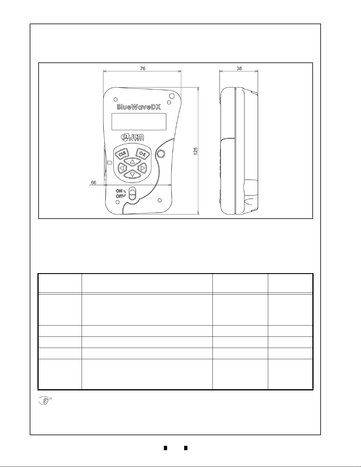
8 UNIT DIMENSIONS
DT-300 E
NTIRE UNIT OUTSIDE DIMENSIONS
Figure 55 illustrates the DT-300™ entire Unit outside dimensions.
All Dimension are
in Millimeters
Figure 55 DT-300 Download Tool Outside Dimensions
NOTE: The Destination Folder intended for download to the specific DT-300 Device must be EXACTLY as
shown in the Table 18 Column, including the “Space” existing before the word “System”.
Twenty (20) Software Programs can be saved in the DT-300 Destination Folder. If saving over twenty (20)
Software Programs in the DT-300 Device, the functions may not work properly.
9 COMPATIBILITY
Table 18 lists the Validator Types compatible with the “BlueWaveDX” DT-300™ Device. Refer to the
“DT-300 Software Storage Destination Folder” Column to create the proper compatible Validator's
Destination Folder for each DT-3
Compatible
Validator
DIP Switch Settings are not required.
UBA Series
iVIZION Series
VEGA Series
TBV-100 Series
iPRO Series
UBA Series downloading is available when the DT-300 Status
is either “
necessary to set the DT-300 into “Download Mode”, set DIP
Switches #6, #7 & #8 to ON, and keep DIP Switches #1
through #5 in their OFF position.
Set DIP Switches #6, #7 & #8 to ON, and keep DIP Switches
#1 thr
Set DIP Switches #1, #7 & #8 to ON, and keep DIP Switches
#2 thr
Set DIP Switches #1, #6, #7 & #8 to ON, and keep DIP
Switches #2 th
DIP Switch Settings are not required.
iPRO Series downloading is available when the DT
is either “Download Mode” or not “Download Mode”. If it is
necessary to set the DT-300 into “Download Mode”, set DIP
Switches #6, #7 & #8 to ON, and keep DIP Switches #1
through #5 in their OFF position.
Download Mode” or not “Download Mode”. If it is
ough #5 OFF.
ough #6 OFF.
00™ Device being Programmed.
Table 18 DT-300 Compatible Validators
Validator Download Setting
rough #5 OFF.
-300 Status
DT-300 Software
Storage Destination
USB Connection
Folder
UBA System Type A - Type B
iVIZION System Type A - Mini B
VEGA System Type A - Mini B
TBV-100 System Type A - Mini B
iPRO System Type A - Mini B
P/N 960-000167R_Rev. 1 {EDP #214645} © 2013, Japan CashMachine Co., Limited

15
DT-300™ Series Download Tool Operator Integration Guide
NOTE: The Detailed Error Code “Dxxx” description is actually the same as the Error Code “Exxx” but
contains more information concerning the error.
10 ERROR CODES
This portion provides the Error Codes displayed on the LCD Display Screen when an error occurs.
B
OOTLOADER ERROR CODES
Table 19 lists the Bootloader Error Codes.
Table 19 Bootloader Error Codes
No. Error Code Error Message Description Remark
1 E01
2 E50 System Error. There is no valid Main Application
3 E51 Battery Low! Battery EMPTY
4 E52 Update Error. Firmware File Version Error Same Version or old Version
5 E53 Update Error. Firmware File Open Error
6 E54 Update Error. Firmware File Access Error
7 E55 Update Error. Firmware File Format Error
8 E56 Update Error. Firmware File Write Error
9 E57 EEPROM Error. EEPROM Data File Open Error
10 E58 EEPROM Error. EEPROM Data File Access Error
11 E59 EEPROM Error. EEPROM Data File Format Error
12 E60 EEPROM Error. EEPROM Write Error
13 E61 SD Card Error. Card Information File Authentication Error
14 E62 SD Card Error. SD Card (MMC Driver) Initialize Error
15 E63 SD Card Error. SD Card Power Control Error
16 E64 SD Card Error. SD Card non-detection Error
17 E65 SD Card Error. SD Card removal-detection Error
18 E66 SD Card Error. SD Card (MMC Driver) Finalize Error
19 E67 SD Card Error. File Relative Initialize Error
20 E68 SD Card Error. File Relative Finalize Error
21 E69 System Error. Task Control Error
22 E70 System Error. Mail Box Control Error
Abnormal Parameter For Debug
M
AINAPPLICATION ERROR CODES
The following two (2) MainApplication Error Code types exist:
Exxx: – Error Code identifying the Error condition.
•
•
Dxxx: – Detailed Error Code for identifying the Error Condition of the error source causing the Error
Code. The Detailed Error Code “
Dxxx” description is same as the Error Code “Exxx”.
Table 20 lists the MainApplication Error Codes.
Table 20 MainApplication Error Codes
No. Error Code Error Message Description Remark
1 E001 Battery Low!
2 E002 SD Card Error. SD Card Error
3 E003 Unit Type Error. Product ID Error
4 E010 USB Error. USB Host Driver Initialize Error
5 E011 USB Error. Open Error
6 E012 USB Error. Control Transfer Error
7 E013 USB Error. Information Receive Error
8 E014 USB Error. Transfer Error
9 E015 USB Error. Close Error
10 E016 USB Error. USB Host Drive Finalize Error
11 E017 USB Error. USB Connection Time Out
12 E018 USB Error. Cancel Error
13 E019 USB Error. Transfer Time Out
14 E030 SD Card Error. File System Initialize Error
Battery EMPTY
P/N 960-000167R_Rev. 1 {EDP #214645} © 2013, Japan CashMachine Co., Limited

16
DT-300™ Series Download Tool Operator Integration Guide
Table 20 MainApplication Error Codes (Continued)
No. Error Code Error Message Description Remark
15 E031 SD Card Error. Mount Error
16 E032 SD Card Error. Non mount Error
17 E033 SD Card Error. Directory Creation Error
18 E034 SD Card Error. File Open Error
19 E035 SD Card Error. File Write Error
20 E036 SD Card Error. File Write Size Error
21 E037 SD Card Error. File Read Error
22 E038 SD Card Error. File Secure Error
23 E039 SD Card Error. File Close Error
24 E040 SD Card Error. File Data Compare Error
25 E041 SD Card Error. File Flash Error
26 E042 SD Card Error. File Detection First Time Error
27 E043 SD Card Error. File Detection Continuous Error
28 E044 SD Card Error. File Detection End Error
29 E045 SD Card Error. File Erase Error
30 E050 EEPROM Error. EEPROM Open Error
31 E051 EEPROM Error. EEPROM Read Error
32 E052 EEPROM Error. EEPROM Write Error
33 E053 EEPROM Error. EEPROM Close Error
34 E054 EEPROM Error. The number of possible EEPROM Read Error
35 E055 EEPROM Error. The number of update EEPROM Read Error
36 E056 EEPROM Error. EEPROM Update Error
37 E057 EEPROM Error. EEPROM Selected Language Read Error
38 E058 EEPROM Error. EEPROM Selected Language Write Error
39 E070 SD Card Error. MMC Driver Initialize Error
40 E071 SD Card Error. SD Card Power ON Error
41 E072 SD Card Error. SD Card Power OFF Error
42 E073 SD Card Error. SD Card non-placed Error
43 E100 Unit Type Error. Log Unsupported Model Error
44 E101 File Error. Log File Name Creation Error
45 E102 File Error. Log File Open Error
46 E103 File Error. Log File Write Error
47 E104 File Error. Log File Close Error
48 E105
49 E106 Mode Error. SetMode (0x01) Command Send Error
50 E107 Mode Error. SetMode (0xFF) Command Send Error
51 E108 Log Read Error. Log Receive Request Retry Error
52 E109 Checksum Error. Log Checksum Error
53 E110 File Error. Log File Conversion Error
54 E200 File Error. Firmware File Open Error
55 E201 File Error. Firmware File Version Error
56 E202 File Error. Firmware File Read Error
57 E203 File Error. Firmware File Close Error
58 E204 Update Count Error. The number of possible Firmware update Error
59 E300 Send Error. Status Request Error
60 E301 Receive Error. Status Response Error
61 E302 Send Error. Download Start Request Error
62 E303 Receive Error. Download Start Response Error
63 E304 Send Error. Download Data Size Send Error
64 E305 Send Error. Download Data Send Error
File Error. Log File Read Error
P/N 960-000167R_Rev. 1 {EDP #214645} © 2013, Japan CashMachine Co., Limited

17
DT-300™ Series Download Tool Operator Integration Guide
Table 20 MainApplication Error Codes (Continued)
No. Error Code Error Message Description Remark
65 E306 Receive Error. Download Data Response Error
66 E307 Send Error. Download Finalize Request Error
67 E308 Receive Error. Download Finalize Response Error
68 E309 Send Error. Version Number Request Error
69 E310 Receive Error. Version Number Response Error
70 E311 Reset Error. Reset Request Error
71 E312 Mode Error. SetMode (0x00) Command Send Error
72 E313 Mode Error. SetMode (0xFF) Command Send error
73 E350 Receive Error. Status Request Retry Error
74 E351 Receive Error. Download Start Request Retry Error
75 E370 Reset Error. Reset Request Error (Control Transfer)
76 E380 Unit Busy Error. Downloaded Firmware Status Error
77 E381 CRC Check Error, Downloaded Firmware CRC Error
78 E382 Version Error. Downloaded Firmware Version Error
79 E400 Send Error. Enable Denomination Receive Start Request Error
80 E401 Receive Error. Enable Denomination Receive Start Response Error
81 E402 DSend Error. Enable Denomination ENG Request Error
82 E403 Receive Error. Enable Denomination ENQ Response Error
83 E404 Mode Error. SetMode (0x0A) Command Send Error
84 E405 Mode Error. SetMode (0xFF) Command Send error
85 E420 Send Error. Error Code Receive Request Error
86 E421 Receive Error. Error Code Receive Response Error
87 E422 Mode Error. SetMode (0x0A) Command Send Error
88 E423 Mode Error. SetMode (0xFF) Command Send Error
89 E440 Send Error. Maintenance Request Error
90 E441 Receive Error. Maintenance Response Error
91 E442 Mode Error. SetMode (0x0A) Command Send Error
92 E443 Mode Error. SetMode (0xFF) Command Send Error
93 E460 Send Error. Version Request Error
94 E461 Receive Error. Version Response Error
95 E462 Send Error. CRC16 Request Error
96 E463 Receive Error. CRC16 Response Error
97 E464 Send Error. Serial Request Error
98 E465
99 E480 Unit Type Error. Limited number of unsupported model Error
100 E481 File Error. Limited number of log file name creation Error
101 E482 File Error. Limited number of log file open Error
102 E483 File Error. Limited number of log file write Error
103 E484 File Error. Limited number of log close Error
104 E485 File Error. Limited number of log file read Error
105 E486 Mode Error. SetMode (0x01) Command Send Error
106 E487 Mode Error. SetMode (0xFF) Command Send Error
107 E488 Log Read Error. Limited number of log request Error
108 E489 Checksum Error. Limited number of log checksum Error
109 E490 File Error. Limited number of log file conversion Error
Receive Error. Serial Response Error
P/N 960-000167R_Rev. 1 {EDP #214645} © 2013, Japan CashMachine Co., Limited

18
DT-300™ Series Download Tool Operator Integration Guide
or
or or
or
CE Warning
This is a class A product. In a domestic environment this product may cause radio interference in which case the User may be
required to take adequate measures.
FCC WARNING
Changes or modifications not expressly approved by the party responsible for compliance could void the user’s authority to
operate the equipment.
FCC NOTICE
This equipment complies with Part 15 of FCC Rules. Operation is subject to the following two conditions: (1) this device may not
cause interference, and (2) this device must accept any interference received, including interference that may cause undesired
operation.
This equipment generates, uses and can radiate radio frequency energy and, if not installed and used in accordance with the
instructions, may cause harmful interference to radio communications. Operation of this equipment in a residential area is likely to
cause harmful interference in which case the user will be required to correct the interference at his own expense.
IC NOTICE
This class A digital apparatus complies with Canadian ICES-003.
Cet appareil numerique de la classe A est conforme a la norme NMB-003 du Canada.
11 INTERNATIONAL COMPLIANCE
• RoHS Directives
• CE Mark
• FCC Directives .
P/N 960-000167R_Rev. 1 {EDP #214645} © 2013, Japan CashMachine Co., Limited

19
DT-300™ Series Download Tool Operator Integration Guide
12 TECHNICAL CONTACT INFORMATION
To obtain further Technical Information regarding the DT-300™ Device, please contact the closest office
listed below:
A
MERICA
JCM A
MERICAN
Phone: +1-702-651-0000
Fax: +1-702-644-5512
925 Pilot Road, Las Vegas, NV 89119
E-mail: support@jcmglobal.com
E
UROPE
JCM E
, A
FRICA
UROPE GMB
, R
H
USSIA
& M
Phone: +49-211-530-645-60
Fax: +49-211-530-645-65
Muendelheimer Weg 60
D-40472 Duesseldorf Germany
E-mail: support@jcmglobal.eu
UK & I
JCM E
RELAND
UROPE
(UK O
FFICE
)
Phone: +44(0)190-837-7331
Fax: +44 (0) 190-837-7834
Unit B, Third Avenue
Denbigh West Business Park
IDDLE EAST
A
SIA
& O
CEANIA
JCM G
OLD
(HK) LTD.
Phone: +852-2429-7187
Fax: +852-2929-7003
Unit 1-7, 3/F., Favor Industrial Centre
2-6 Kin Hong Street, Kwai Chung,
N.T. Hong Kong
E-mail: asiapactechsuppor
J
APAN CASH MACHINE CO
t@jcmglobal.com
, L
IMITED
(HQ)
Phone: +81-6-6703-8400
Fax: +81-6-6707-0348
2-3-15, Nishiwaki, Hirano-ku, Osaka 547-0035
JAP
AN
E-mail: Shohin@jcm-hq.co.jp
All of these Websites are available via:
http:/
/www.jcmglobal.com
Bletchley, Milton Keynes,
Buckinghamshire MK1 1DH UK
E-mail: support@jcm-uk.com
P/N 960-000167R_Rev. 1 {EDP #214645} © 2013, Japan CashMachine Co., Limited

20
DT-300™ Series Download Tool Operator Integration Guide
THIS PAGE INTENTIONALLY LEFT BLANK
P/N 960-000167R_Rev. 1 {EDP #214645} © 2013, Japan CashMachine Co., Limited

DT-300™ Series
21
13
INDEX
Operator Integration Guide
Index
C
Cautions
special boxed areas providing important safty
information… 3
Contact Information
Address and Telephone Numbers for… 19
D
Dimensions
entire unit clearance
illustrated drawing for… 14
DT-300 Device
photo of a… 1
I
Installation
steps required for… 5
N
Navigation
within manual
procedure for… 1
P
Pin Assignments
51-Pin-D Sub Connector
Table Listing of… 13
Precautionary Symbols
types of… 3
Primary Features
DT-300 Product Series… 2
S
Safety
Pictographs indicating
1 to 3 symbols inside boxed area… 1
Special Notes
italic text highlights
finger points to… 1
Specifications
Electrical
Table listing of… 4
Environmental
Table listing of… 4
Structural
Table listing of… 4
Technical
Table listing of… 4
Steps
sequential numbering of… 1
Symbols
Precautionary
definitions of… 3
P/N 960-000167R_Rev. 1 {EDP #214645} © 2013, Japan CashMachine Co., Limited

22
DT-300™ SeriesOperator Integration Guide
THIS PAGE INTENTIONALLY LEFT BLANK
P/N 960-000167R_Rev. 1 {EDP #214645} © 2013, Japan CashMachine Co., Limited

DT-300™ SeriesOperator Integration Guide
P/N 960-000167R_Rev. 1 {EDP #214645} © 2013, Japan CashMachine Co., Limited

DT-300™ SeriesOperator Integration Guide
Issue #4033-IGE-01-01
P/N 960-000167R_Rev. 1 {EDP #214645} © 2013, Japan CashMachine Co., Limited
 Loading...