

Page 1
Web site: http://www.jcmglobal.com
UBA Pro RT/RQ™ Series
Banknote Recycler
Integration Guide
Revision A, October 23, 2019
P/N 960-000209R_Rev. A
Issue #4115-IGE-01-00
© 2019, JAPAN CASH MACHINE CO., LTD.
Page 2

UBA Pro RT/RQ™ Series Banknote Recycler Integration Guide
See Below.
See Below.
See Below.
See Below.
See Below.
Issue #4115-IGE-01-00
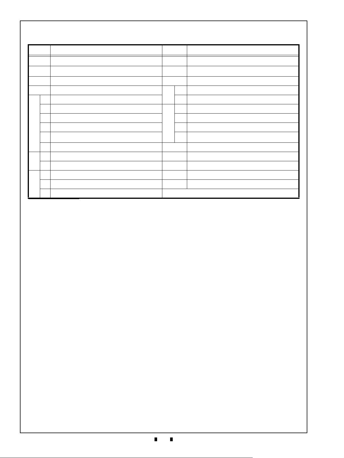
REVISION HISTORY
Rev №. Date Reason for Update Comment
A Oct. 23, 2019 Initial Document
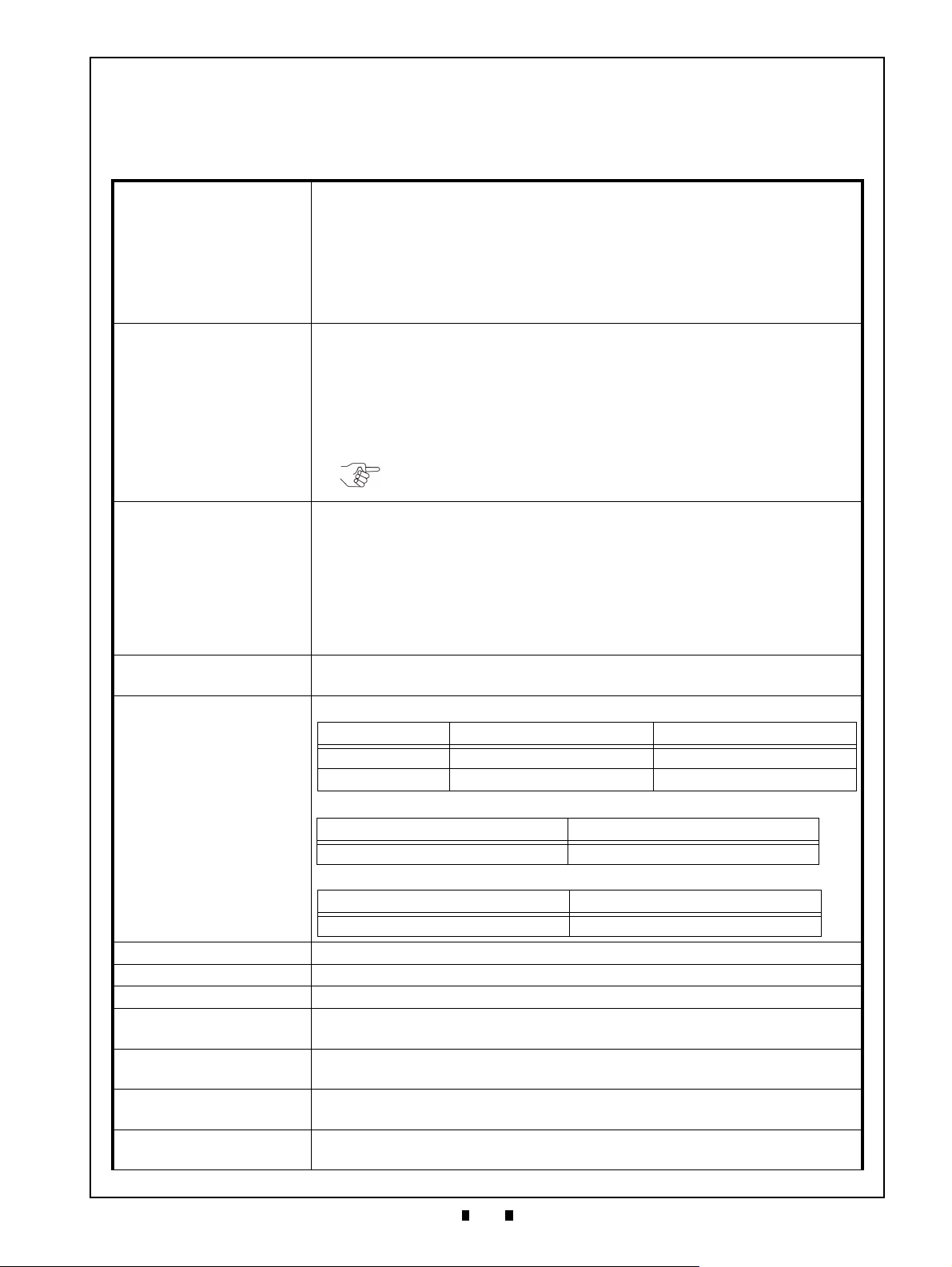
International Compliance
• RoHS Directives
• UL & c-UL Marks
• CE Mark
• CB Scheme
• FCC & ISED Regulations
NOTE: All the compliance confirmations above are currently being examined for approval.
Electrical Current Symbol
Direct Current: indicates Direct Current values on product labels.
Copyright © 2019 By JAPAN CASH MACHINE CO., LTD.
This product document (hereinafter referred to as “Manual”) is fully covered by legal Copyrights owned by the JAPAN
CASH MACHINE CO., LTD. (hereinafter referred to as “JCM”) under Japanese laws and other Foreign Countries.
This Manual contains many copyrighted, patented or properly registered equipment items manufactured by JCM, that
are prohibited and illegal to duplicate, replicate, copy in whole, or in part, without the express authorization by JCM with
the following exceptions:
1. When an authorized JCM agency or distributor duplicates the Manual for sales promotion and/or service
maintenance of the product, or technical service personnel education as required; and
2. When an end user duplicates the Manual to maintain operation of the product or operate the product in general.
JCM retains all rights to amend, alter, change or delete any portion of this Manual in whole, or in part, or add items
thereto without notice regarding the product or its related products.
JCM is a registered trademark of JAPAN CASH MACHINE CO., LTD. All other product names mentioned herein may be
registered trademarks or trademarks of their respective companies. Furthermore,
in each case throughout this publication.
™, ® and © are not always mentioned
Page 3

UBA Pro RT/RQ™ Series
i
Banknote Recycler
Table of Contents
Page
1 GENERAL INFORMATION ........................................................................................1
RT and RQ Units.................................................................................................................1
Model Descriptions............................................................................................................2
Type Descriptions..............................................................................................................2
Software Descriptions .......................................................................................................2
Precautions.........................................................................................................................2
User Cautions ......................................................................................................................3
Installation Cautions........................................................................................................................ 3
Mounting, Dismounting & Transportation........................................................................................ 3
Operation Cautions ......................................................................................................................... 3
Preventive Maintenance.......................................................................................................3
Disposal Considerations ......................................................................................................4
Banknote Fitness Requirements..........................................................................................4
Primary Features................................................................................................................4
Transport UnitComponent Names....................................................................................5
2 SPECIFICATIONS ......................................................................................................7
Technical Specifications ......................................................................................................7
Environmental Specifications ......................................................................................................... 8
Electrical Specifications .......................................................................................................8
Structural Specifications.......................................................................................................8
3 INSTALLATION ..........................................................................................................9
Installation Procedure .......................................................................................................9
Grounding ...........................................................................................................................9
Side Installation (For Standard and Stacking Up (SU) Installation types)............................9
Bottom Installation (For Standard Installation Type Only)..................................................10
Bezel Installation ................................................................................................................10
External Harness Installation .............................................................................................10
Cash Box Lock Installation.................................................................................................10
Unlock Procedure...............................................................................................................11
DIP Switch Configurations ..............................................................................................11
Denomination Acceptance Settings (DIP Switches at the front) ........................................11
SW1 and SW2 Configurations ...........................................................................................11
Interface and Recycler Settings (Sub Board 2)..................................................................12
LED Flashing Patterns.....................................................................................................13
4 CONNECTOR PIN ASSIGNMENTS.........................................................................14
USB Interface Connector Pin Assignments (UBA Pro Side)..............................................14
Photo Coupler Interface Connector Pin Assignments (UBA Pro Side) ..............................15
RS232C Interface Connector Pin Assignments (UBA Pro Side)........................................16
cc-Talk Interface Connector Pin Assignments (UBA Pro Side)..........................................17
Power Supply Connector Pin Assignments (RT/RQ Side).................................................18
Interface Connector Pin Assignments (RT/RQ Side).........................................................18
Bezel Connector Pin Assignments (UBA Pro Side) ...........................................................18
5 PREVENTIVE MAINTENANCE ................................................................................19
P/N 960-000209R_Rev. A © 2019, JAPAN CASH MACHINE CO., LTD.
Page 4

ii
UBA Pro RT/RQ™ Series Banknote Recycler
Table of Contents
Page
Refilling Banknotes..........................................................................................................19
Collecting Banknotes ......................................................................................................19
Collecting Banknotes into the Cash Box by the Button......................................................19
Collecting Banknotes into the Cash Box by Command......................................................19
Dispense Settings ..............................................................................................................19
Clearing a Banknote Jam ................................................................................................20
Find where a Banknote Jam occurred ...............................................................................20
Jammed in UBA Pro Unit ...................................................................................................20
Jammed in RT Transport Banknote ...................................................................................20
Jammed in RQ Transport...................................................................................................21
Jammed in Recycler Drum.................................................................................................22
Jammed in Cash Box .........................................................................................................22
Cleaning Procedure .........................................................................................................22
Sensor Cleaning Procedure ...............................................................................................22
Sensor, Roller and Belt Cleaning Locations.......................................................................24
6 STANDARD INTERFACE CIRCUIT SCHEMATICS................................................ 27
Bezel Connector Interface Circuit Schematics...................................................................27
RT/RQ Interface Circuit Schematics (Sub Board 2)...........................................................28
7 OPERATIONAL FLOWCHART ............................................................................... 29
RT/RQ Main Flow Process.................................................................................................29
RT/RQ Accepting Banknotes Flow Process.......................................................................30
RT/RQ Transporting to Recycler Flow Process .................................................................31
RT/RQ Transporting to Cash Box Flow Process................................................................32
RT/RQ Dispensing Flow Process (Normal)........................................................................33
RT/RQ Dispensing Flow Process (Abnormal)....................................................................34
RT/RQ Collecting in Cash Box Flow Process1 ..................................................................34
RT/RQ Collecting in Cash Box Flow Process 2 .................................................................35
8 TROUBLESHOOTING ............................................................................................. 36
Introduction ......................................................................................................................36
Troubleshooting Overview..............................................................................................36
LED Error Codes ..............................................................................................................36
9 UNIT DIMENSIONS.................................................................................................. 39
RT Unit With SH2 Box Outside Dimensions and Installation/Maintenance Space
Requirement.......................................................................................................................39
RT Unit With SH2 Box Outside Dimensions and Installation/Maintenance Space
Requirement.......................................................................................................................40
RQ Unit With SH2 Box Outside Dimensions and Installation/Maintenance Space
Requirement.......................................................................................................................41
RQ Unit With Large Box Outside Dimensions and Installation/Maintenance Space
Requirement.......................................................................................................................42
Bezel Outside Dimensions .................................................................................................43
10 TECHNICAL CONTACT INFORMATION ................................................................ 44
Americas ............................................................................................................................44
JCM American ...............................................................................................................................44
Europe, Middle East, Africa & Russia ................................................................................44
P/N 960-000209R_Rev. A © 2019, JAPAN CASH MACHINE CO., LTD.
Page 5

iii
UBA Pro RT/RQ™ Series Banknote Recycler
Table of Contents
Page
JCM Europe GmbH....................................................................................................................... 44
UK & Ireland.......................................................................................................................44
JCM Europe (UK Office) ............................................................................................................... 44
Asia and Oceania...............................................................................................................44
JCM Gold (HK) Ltd........................................................................................................................ 44
JAPAN CASH MACHINE CO., LTD. (HQ) .................................................................................... 44
11 INDEX .......................................................................................................................45
P/N 960-000209R_Rev. A © 2019, JAPAN CASH MACHINE CO., LTD.
Page 6

iv
THIS PAGE INTENTIONALLY LEFT BLANK
P/N 960-000209R_Rev. A © 2019, JAPAN CASH MACHINE CO., LTD.
Page 7
v
UBA Pro RT/RQ™ Series
Banknote Recycler
List of Figures
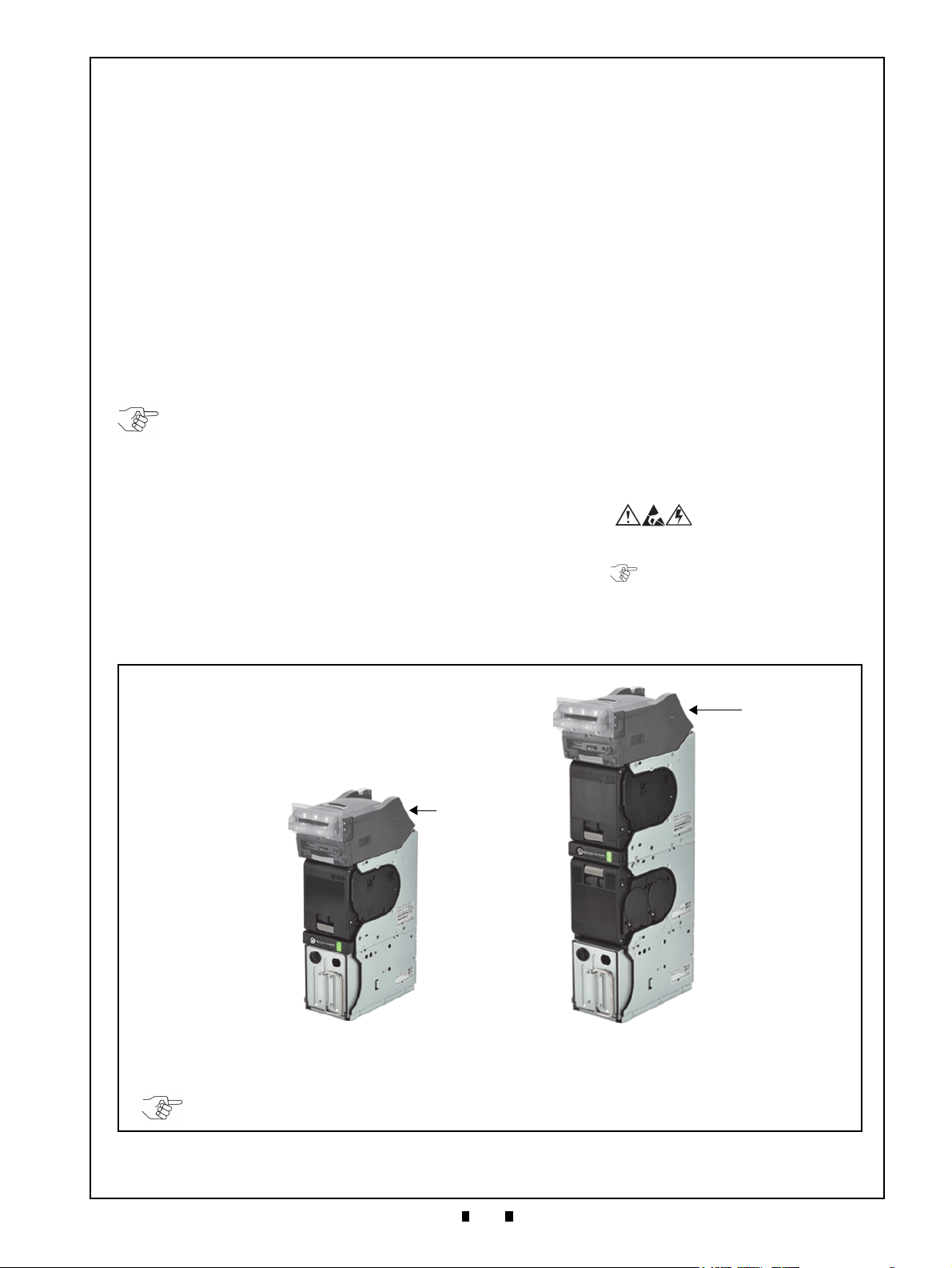
Figure 1 RQ and RT Units ........................................................................................1
Figure 2 Precautionary Symbols ..............................................................................2
Figure 3 Unacceptable Banknotes ...........................................................................4
Figure 4 RT/RQ Component Locations ....................................................................5
Figure 5 Grounding ..................................................................................................9
Figure 6 Side Installation (Standard and SU Installation Types) ..............................9
Figure 7 Bottom Installation (Standard Installation Type) ......................................10
Figure 8 Bezel Installation ......................................................................................10
Figure 9 External Harness Installation ...................................................................10
Figure 10 Key Hole Location ....................................................................................10
Figure 11 Key Hole Dimension & Cylinder Length ...................................................11
Figure 12 Key Lock Rotation Requirement ..............................................................11
Figure 13 Key Cap Installation .................................................................................11
Figure 14 SW1 and SW2 Switches ..........................................................................11
Figure 15 Refilling Banknotes ..................................................................................19
Figure 16 Collecting Banknotes 1 ............................................................................19
Figure 17 Collecting Banknotes 2 ............................................................................19
Figure 18 UBA Pro Unit Banknote Jam Clear ..........................................................20
Figure 19 RT Transport Banknote Jam Clear 1 .......................................................20
Figure 20 RT Transport Banknote Jam Clear 2 .......................................................20
Figure 21 RT Transport Banknote Jam Clear 3 .......................................................20
Figure 22 RT Transport Banknote Jam Clear 4 .......................................................20
Figure 23 RT Transport Banknote Jam Clear 5 .......................................................21
Figure 24 RQ Transport Banknote Jam Clear 1 .......................................................21
Figure 25 RQ Transport Banknote Jam Clear 2 .......................................................21
Figure 26 RQ Transport Banknote Jam Clear 3 .......................................................21
Figure 27 RQ Transport Banknote Jam Clear 4 .......................................................21
Figure 28 RQ Transport Banknote Jam Clear 5 .......................................................21
Figure 29 Recycler Drum Banknote Jam Clear 1 .....................................................22
Figure 30 Recycler Drum Banknote Jam Clear 2 .....................................................22
Figure 31 Recycler Drum Banknote Jam Clear 3 .....................................................22
Figure 32 Cash Box Banknote Jam Clear ................................................................22
Figure 33 Sensor and Roller Cleaning .....................................................................23
Figure 34 RT/RQ Sensor, Roller and Belt Cleaning Locations ................................24
Figure 35 Bezel Connector Interface Circuit Schematics .........................................27
Figure 36 RT/RQ Interface Circuit Schematics (Sub Board 2) .................................28
Figure 37 RT/RQ Main Flow Process .......................................................................29
Figure 38 RT/RQ Accepting Banknotes Flow Process .............................................30
Figure 39 RT/RQ Transporting to Recycler Flow Process .......................................31
Figure 40 RT/RQ Transporting to Cash Box Flow Process ......................................32
Figure 41 RT/RQ Normal Dispensing Flow Process ................................................33
Figure 42 RT/RQ Abnormal Dispensing Flow Process ............................................34
Figure 43 RT/RQ Collecting in Cash Box Flow Process 1 .......................................34
Page
P/N 960-000209R_Rev. A © 2019, JAPAN CASH MACHINE CO., LTD.
Page 8
vi
UBA Pro RT/RQ™ Series Banknote Recycler
List of Figures
Page
Figure 44 RT/RQ Collecting in Cash Box Flow Process 2 ....................................... 35
Figure 45 RT Unit With SH2 Box Outside Dimension and Installation/
Maintenance Space Requirement ........................................................... 39
Figure 46 RT Unit With Large Box Outside Dimension and Installation/
Maintenance Space Requirement ........................................................... 40
Figure 47 RQ Unit With SH2 Box Outside Dimension and Installation/
Maintenance Space Requirement ........................................................... 41
Figure 48 RQ Unit With Large Box Outside Dimension and Installation/
Maintenance Space Requirement ........................................................... 42
Figure 49 Bezel Outside Dimensions ...................................................................... 43
P/N 960-000209R_Rev. A © 2019, JAPAN CASH MACHINE CO., LTD.
Page 9

vii
UBA Pro RT/RQ™ Series
Banknote Recycler
List of Tables
Table 1 RT/RQ Product Model Number Specifications............................................2
Table 2 RT/RQ Type Number Specifications...........................................................2
Table 3 RT/RQ Software Number Specifications.....................................................2
Table 4 RT/RQ Component Names.........................................................................6
Table 5 RT/RQ Technical Specifications .................................................................7
Table 6 RT/RQ Environmental Specifications..........................................................8
Table 7 RT/RQ Electrical Specifications ..................................................................8
Table 8 RT/RQ Structural Specifications .................................................................8
Table 9 Denomination Acceptance Settings ..........................................................11
Table 10 Sub Board 2 Interface Settings .................................................................12
Table 11 Recycler and Transport LEDs Flashing Patterns ......................................13
Table 12 Status LED Flashing Patterns ...................................................................13
Table 13 USB Interface Connector Pin Assignments (UBA Pro Side).....................14
Table 14 Photo Coupler Interface Connector Pin Assignments (UBA Pro Side) .....15
Table 15 RS232C Connector Pin Assignments (UBA Pro Side)..............................16
Table 16 cc-Talk Interface Connector Pin Assignments (UBA Pro Side).................17
Table 17 Power Supply Connector Pin Assignments (RT/RQ Side)........................18
Table 18 Interface Connector Pin Assignments (RT/RQ Side) ................................18
Table 19 Bezel Connector Pin Assignments (UBA Pro Side) ..................................18
Table 20 RT/RQ Sensor Cleaning Methods.............................................................25
Table 21 LED Error Codes.......................................................................................36
Page
P/N 960-000209R_Rev. A © 2019, JAPAN CASH MACHINE CO., LTD.
Page 10

viii
THIS PAGE INTENTIONALLY LEFT BLANK
P/N 960-000209R_Rev. A © 2019, JAPAN CASH MACHINE CO., LTD.
Page 11
UBA Pro RT/RQ™ Series
1
1 GENERAL INFORMATION
NOTE: Refer to the UBA Pro Series
Universal Banknote Acceptor Integration
Guide for the UBA Pro product‘s details.
RT and RQ Units
Figure 1 RQ and RT Units
Figure 1 RQ and RT Units
RT Unit
RQ Unit
UBA Pro
(1 Recycler, Twin Drums)
(2 Recyclers, Quad Drums)
NOTE: The Stacking Up (SU) installation is also available by using a specified SU Bezel.
UBA Pro
Banknote Recycler
Integration Guide
Revision A
This section provides a general overview of the
UBA Pro RT/RQ™ Series Banknote Recycler (RT/
RQ) pictured in Figure 1.
The RT/RQ Unit is a Banknote Recycler compatible with the UBA Pro Series Universal Banknote
Acceptor.
This section is designed to help you navigate
through this guide with ease, and provides the following information:
• RT and RQ Units
• Model Descriptions
• Type Descriptions
• Software Descriptions
• Precautions
• Primary Features
• Component Names
• Specifications
• Unit Dimensions
• Technical Contact Information
In order to make operation of this device easier and
make navigation within this manual simpler, the
following illustrations were used within the text:
• Safety Instructions need to be observed in order to
protect the operators and the equipment; these are
identified with Bold text and the following
pictographs:
• Special Notes affect the use of the RT/RQ Unit;
these are identified with italic text and the following
pictograph:
• Steps require the operator to perform specific
actions; these are identified with sequential
numbers (1, 2, 3, etc.).
P/N 960-000209R_Rev. A © 2019, JAPAN CASH MACHINE CO., LTD.
Page 12
2
Section 1 UBA Pro RT/RQ™ Series Banknote Recycler General Information
Model: UBA - 5 * 0 - (*) * * (*) - * *
(1)
(2)(3)(4) (6) (7) (8)(5)
Typ e: * * * - * * - * * * * * * *
(1)(2)(3)
(4)
(6)(7)(8)(9)(10)(11)(12)
(5)
Typ e: * * * - * * - * * * * * * *
(1)(2)(3)
(4)
(6)(7)(8)(9)(10)(11)(12)
(5)
(A)
(D)
UBA-5**-(*)**(*)-RC-T/Q * * * - 0 * * - V * .**
(B) (C)
Caution: User cautions should be
included in any user guides or manuals.
Figure 2 Precautionary Symbols
Type1 Type2 Type3
Figure 2 Precautionary Symbols
NOTE: Refer to “Banknote Fitness
Requirements” on page 4.
Model Descriptions
Table 1 lists the RT/RQ Product Model Number Descriptions.
Table 1 RT/RQ Product Model Number
Specifications
o
N
(1)
Model Name (UBA Pro Series)
Validation Sensor
(2)
5 = World Wide Type 1 (Standard)
6 = Reserved
Barcode Sensor Board (Optional)
(3)
0 = Upper only (Standard)
1 = Upper and Lower
Acceptor Head Unit Type
(4)
0 = Centering Type (Banknote Short Side: 62mm - 85mm)
1 = Reserved
Input Section Unit (Optional)
(5)
None = Standard
Stacking Type
(6)
SH2 = Horizontal Down (82mm, SH2 Box)
SS = Vertical Down (85mm, Large Box)
Cash Box Access
(7)
None = Front Access (Standard)
Recycler Type
(8)
RT = 1 Recycler (Twin Drums)
RQ = 2 Recyclers (Quad Drums)
*. Refer to the UBA Pro Series Universal Banknote Acceptor Integration Guide for
the UBA Pro Unit’s details.
†. The acceptable Banknote width depends on the Cash Box. Refer to “Technical
Specifications” on page 7 for each Cash Box’s acceptable Banknote size.
*
†
Type Descriptions
Table 2 lists the RT/RQ Type Number Descriptions.
Table 2 RT/RQ Type Number Specifications
Tab le 2 RT/RQ Type Number Specifications
o
N
Interface Setting (Factory Default)
(9)
P = Photo-Coupler Isolation
R = RS232C
External Harness
0 = Reserved
(10)
1 = Standard Harness (with power cord)
2 = USB I/F Harness (with power cord)
Cash Box Faster/Lock (Optional)
(11)
0 = None
1 = Thumb Twist Lock Fastener for the Cash Box
Battery (For Recycler Detection)
(12)
0 = No Battery
1 = Battery Equipped
*. Small pieces of paper or receipts might accidentally be inserted into the UBA Pro
Unit. The Bezel Spacer makes the distance to the Sensor longer and the Sensor
may not detect such foreign objects. Also, small pieces of paper or receipts are difficult to detect and remove.
†. Refer to “SW1 and SW2 Configurations” on page 11 for details.
†
Software Descriptions
Table 3 lists the RT/RQ Software Number
Descriptions.
Table 3 RT/RQ Software Number Specifications
o
N
(A) Software Model Name
(B)
Country Code (Denomination)
(C) Interface Protocol Name
(D) Software Version
*. The Country Code is indicated by three (3) Alphabetical Characters following the
JIS Standard.
*
Precautions
o
N
Cash Box Capacity
(1)
4 = 400 notes, SH2 Box (New Banknote)
8 = 800 notes, Large Box, (New Banknote)
Cash Box Type
(2)
0 = Standard
Cash Box Handle
(3)
0 = Standard
Sub Board Type
0 = Reserved
1 = Reserved
(4)
2 = Sub Board 2 (RS232/Photo-Coupler Isolation/TTL/ccTalk/1 USB)
3 = Reserved
4 = Reserved
Acceptor Head Unit Cover
(5)
0 = Black (Standard)
Bezel
0 = No Bezel
1 = Black/2 Green LEDs (Bezel 85) (Standard Installation)
2 = Reserved
(6)
8 = Reserved
9 = Reserved
A = Reserved
B = Black/2 Blue LEDs (SU Installation)
Bezel Spacer
(7)
0 = No Bezel Spacer
1 = With Bezel Spacer
Optional Circuit Board
(8)
0 = Reserved
*
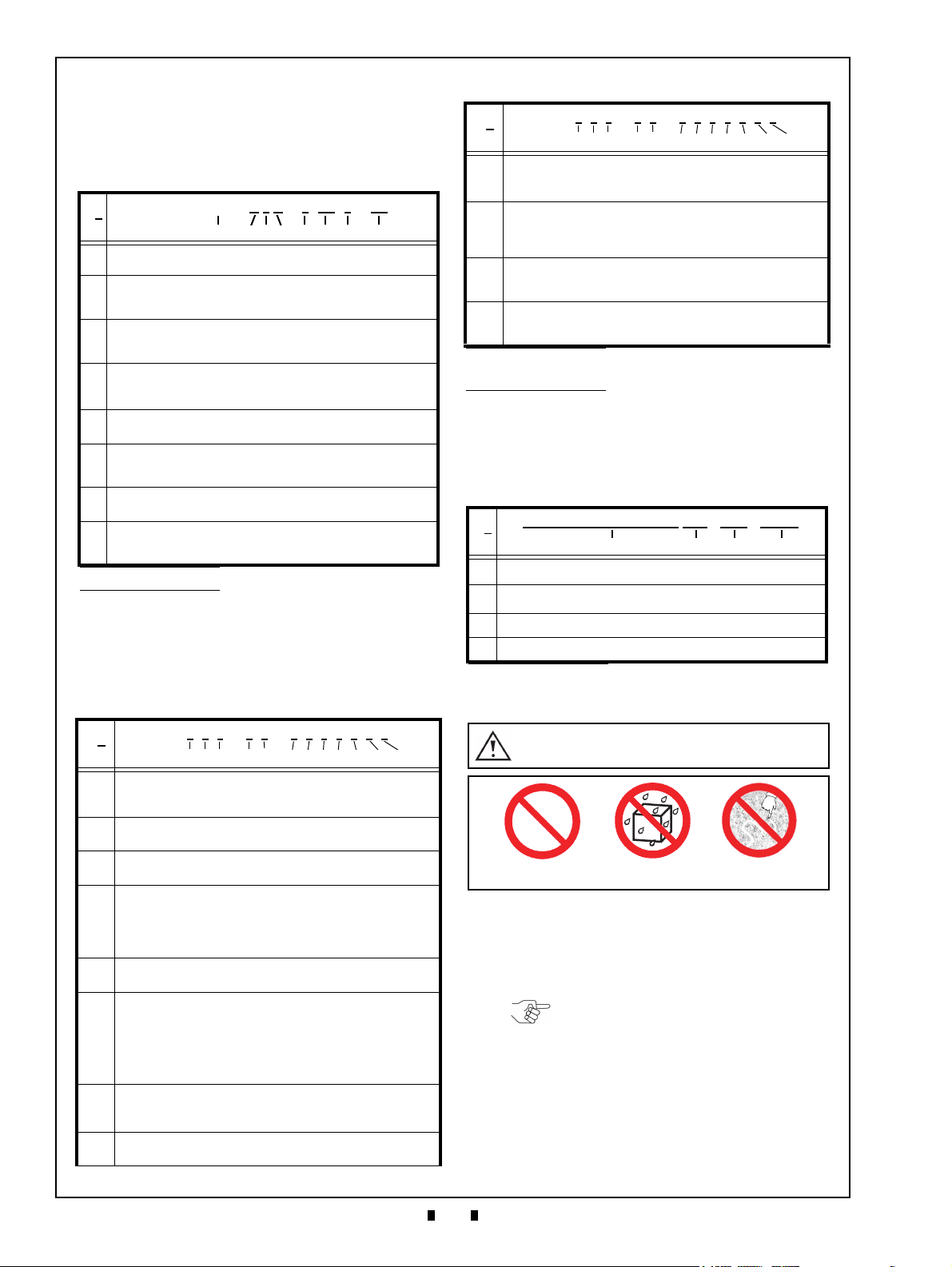
The Figure 2 symbols are defined as follows:
1. (Type 1) Do not insert a damaged or exhibited
unfit condition Banknote; it may cause a jam
inside the unit.
2.
(Type 2) Do not expose the unit to water. The unit
contains several precision electronic devices that
can be damaged if water or any liquid is sprayed
or spilled into the unit.
3.
(Type 3) Do not install the unit in a dusty
environment. Dust may damage the unit or
degrade its performance.
P/N 960-000209R_Rev. A © 2019, JAPAN CASH MACHINE CO., LTD.
Page 13
3
General Information UBA Pro RT/RQ™ Series Banknote Recycler Section 1
Caution: DO NOT use any alcohol,
solvents, abrasive cleaning agents,
or citrus-based cleaners that can
damage the plastic surface of the
device when cleaning it.
WARNING: This Unit is designed
for use with a Limited Power
Source! Design the Host Cabinet
space to meet all local related
safety standards.
Caution: Make Interface Harness
connections to the Host Machine
shorter than 9.84 Feet (3 Meters) in
length. Cut off all unused portions
of the Interface Harness wiring to
avoid static electrical effects or
short circuit possibilities that
could cause damage to the Unit.
User Cautions
Careful measures are taken in the design of this
product to ensure its quality; however, the following cautions should be read and understood by all
users in order to confirm safe operation.
Installation Cautions
The Installation Cautions are defined as follows:
1. Do not allow the Unit to endure or operate at a
high temperature, in high humidity and/or in a
dusty environment.
2. Do not install the Unit into an area where excessive vibration or shock are present.
3. The Unit is not designed for outside installation.
Be sure that the Host Machine contains enough
protection to avoid wet or dusty conditions when
installing in either an indoor or open-air space.
4. Avoid exposing the Unit to direct Sunlight and/or
Incandescent Lamp illumination having a
Gradient Angle of 15 Degree or more, and an
illumination index of 3000 Lux or less.
5. Ensure that the Host Machine is designed for
daily operational access for maintenance and/or
clearing a Banknote jam (refer to “Unit Dimensions” on page 39).
6. When installing the equipment, connect the
Frame Housing to the Frame Ground of the Host
Machine.
7. If an unused Interface Harness exists, cut the
Harness off short to avoid attracting static electricity or a short circuit possibility that may cause
damage to the Unit.
8. Because this equipment is a component product,
close the Host Machine’s door before using it.
9. Do not operate the RT/RQ Unit without the Cash
Box and/or the Recycler or while the Cash Box
and/or the Recycler’s door is open.
10. This Unit is designed to use a Limited Power
Source. Be sure that the Host Machine’s cabinet
material design meets local safety standards.
11. Do not use the Unit where it may be exposed to
airborne evaporated or sporadic chemicals and/or
oil.
12. Ensure that the Host Machine is designed considering the risk of electronic components that can
cause induced noise. The noise generated by the
components on the Host Machine may affect and
degrade the Validation performance.
Mounting, Dismounting & Transportation
Methods for Mounting, Dismounting, and Transporting the Unit are as follows:
1. Be sure to remove the Power from the RT/RQ
Unit before attaching or unplugging Connector
Plugs to avoid the risk of damage to the Unit.
2. Be sure to carry the Unit by both hands when
transporting it. Holding the Unit by one hand
may cause personal injury if the Unit accidentally
becomes disassembled and falls away from the
Frame housing.
3. Be careful not to use excessive outside pressure
on the Recycler, or subject it to excessive vibration during transportation.
P/N 960-000209R_Rev. A © 2019, JAPAN CASH MACHINE CO., LTD.
4. Check that the UBA Pro Unit does not drop off
the Unit Frame while pulling the Recycler forward from the Frame.
Operation Cautions
The Operation Cautions are defined as follows:
1. When closing the UBA Pro Unit, ensure it firmly
clicks into place.
2. When installing the Recycler, ensure it firmly
clicks into place.
3. Do not remove the Recycler and/or the Cash Box
during operation.
4. Do not throw or pound hard on the Recycler.
5. Be sure to follow the specified measures when
removing or re-seating any removal unit of the
RT/RQ Unit. Improper handling may cause personal injury and/or damage to the equipment.
6. The Recycler is not protected by a key. Caution is
advised for cash handling.
Preventive Maintenance
The Preventive Maintenance requirements are
defined as follows:
1. Be sure to remove the Power from the RT/RQ
Unit before beginning a maintenance procedure,
except for the Recycler and the Cash Box. The
equipment produces improper operating signals
while in maintenance mode that may cause personal injury.
2. If the Transport Path and/or Sensors are dirty due
to dust, foreign objects or other such debris
adhering to it, the Banknote acceptance rate will
degrade. Clean the Unit once a month to keep its
performance optimal.
3. Use a soft, lint-free cloth, cotton swab or a compressed air spray to clean dust and debris from
the Banknote path and the inside areas of the
Recycler.
4. Do not redesign or disassemble the Recycler.
Unauthorized use by inadequately-trained
personnel, or use outside the original manufacturer’s intent for operation voids the warranty.
Page 14
4
Section 1 UBA Pro RT/RQ™ Series Banknote Recycler General Information
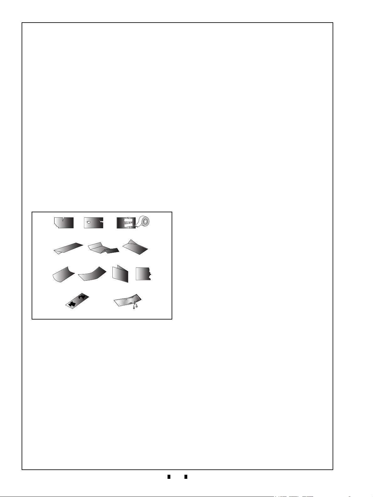
Figure 3 Unacceptable Banknotes
Figure 3 Unacceptable Banknotes
Damaged or Taped Banknotes
Wrinkled or Folded Banknotes
Curled, Folded or Partial Banknotes
Dirty Banknotes
Wet or Oiled Banknotes
Disposal Considerations
The battery disposal requirements are defined as
follows:
1. Do not allow positive (+) and negative (-) battery
terminals to touch each other.
2. Use caution so that batteries stored or transported
together do not short circuit.
3. Follow federal, state and local regulations for
battery disposal.
Banknote Fitness Requirements
The following Banknote types may not validate
correctly, or can cause a Banknote jam and/or damage to the Unit’s Transport path. Banknotes exhibiting the conditions listed below and illustrated in
Figure 3 should be avoided:
• Torn
• Worn
• Taped
• Excessive folds or wrinkles
• Dirty
• Wet
• Adhering foreign objects and/or oil
• Excessive miscuts, misaligns and/or misprints
• The Automatic Centering Mechanism allows the
Unit to read Banknotes ranging from 62 to 85mm in
width, and it will automatically center Banknotes
inserted obliquely to help improve the acceptance
rate (the acceptable Banknote width depends on the
Cash Box).
• Easily access to all the note paths for maintenance
efficiency.
• Able to stack up to 800 Banknotes in the plastic
Cash Box (only Large Box).
• The JCM patented Anti-Pullback Mechanism
provides powerful protection against Banknote
stringing operations.
Primary Features
The RT/RQ Unit contains the following primary
features:
• The RT Unit is equipped with one high capacity
compact Recycler, containing two drums for
recycling two denominations of Banknotes.
• The RQ Unit is equipped with two high capacity
compact Recyclers, each containing two drums for
recycling four denominations of Banknotes.
• Each Recycler’s Drum can store up to 30
Banknotes.
• The Recycler is lockable and removal, and contains
a memory device to assure safe and secure cash
handling.
• Processing speed is approximately double or
greater than the previous UBA-RC Series Units.
P/N 960-000209R_Rev. A © 2019, JAPAN CASH MACHINE CO., LTD.
Page 15
General Information UBA Pro RT/RQ™ Series Banknote Recycler Section 1
5
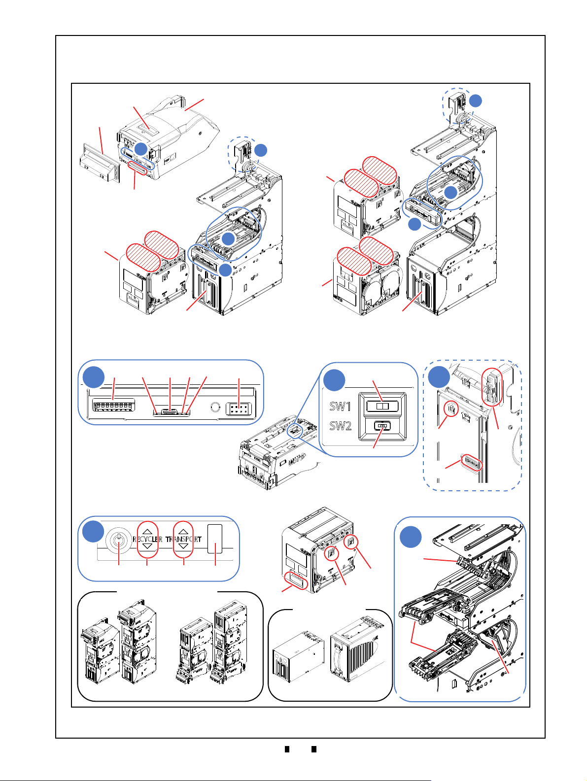
Figure 4 RT/RQ Component Locations
Figure 4 RT/RQ Component Locations
Standard
Stacking Up (SU)
SH2 Box
Large Box
RQ Unit
RT Unit
Recycler Direction
for RT Transport
Recycler Direction
H
1
H
1
I I
D
r
u
m
1
D
r
u
m
2
L
M
}
}
L
}
H
2
D
r
u
m
2
D
r
u
m
1
D
r
u
m
1
D
r
u
m
2
3
4
1
K
2
G
G
K
K
for RQ Transport (flipped)
A
B
C
D
E
J
J
Recycler
N
P
O
Installation Type
Cash Box
UBA Pro Bottom View
5
6
4
3
1
2
E
1
2
F
1
2
G
3
J
1
2
2
Transport UnitComponent Names
Figure 4 illustrates the RT/RQ component names and locations.
P/N 960-000209R_Rev. A © 2019, JAPAN CASH MACHINE CO., LTD.
Page 16
Section 1 UBA Pro RT/RQ™ Series Banknote Recycler General Information
6
Table 4 RT/RQ Component Names
Sym. Description Sym. Description
A Acceptor Head Unit (UBA Pro)
B Upper Guide Access Lever
H
Recycler (RT Transport)
1
H
Recycler (RQ Transport)
2
C Bezel I Cash Box
D Acceptor Head Unit Release Lever
1 Transport Unit
J
1 DIP Switches (Front) 2 Front Transport Unit
2 UBA Pro Status LED (Orange)
1 Recycler Lock
3 USB Type-C Connector (Maintenance) 2 Recycler LED
E
4 UBA Pro Status LED (Green) 3 Transport LED
5 UBA Pro Status LED (Red) 4
K
Status LED/Collect Button
*
6 Bezel Connector L RT Transport
1 SW1 (Bottom) M RQ Transport
F
2 SW2 (Bottom) N Recycler Release Lever
1 Interface Connector O Drum 1 Shaft
G
2 Power Connector P Drum 2 Shaft
3 DIP Switches (Rear) -
*. With the Collect Button (Status LED), the Banknotes are sent from the Recycler into the Cash Box. Refer to “Collecting Banknotes into the Cash Box by the Button” on
page 19.
P/N 960-000209R_Rev. A © 2019, JAPAN CASH MACHINE CO., LTD.
Page 17
Specifications UBA Pro RT/RQ™ Series Banknote Recycler Section 2
7
NOTE: In case of Large Box, a Banknote wider than 82mm (3.22in.)
up to 85mm (3.44in.) is directly transported to the Cash Box.
Destination RT RQ
Collect to Recycler Approx. 2 seconds (to Drum 1) Approx. 2 seconds (to Drum 3)
Collect to Cash Box Approx. 2.9 seconds Approx. 3.2 seconds
RT RQ
Approx. 2 seconds (from Drum 1) Approx. 2 seconds (from Drum 1)
RT RQ
Approx. 2.4 seconds (from Drum 1) Approx. 2.7 seconds (from Drum 1)
2 SPECIFICATIONS
This section provides specifications of the UBA Pro RT/RQ™ Series Banknote Recycler (RT/RQ).
Technical Specifications
Acceptance Rate:
Banknote Types Accepted:
Table 5 RT/RQ Technical Specifications
98% or greater
The following Banknote Types are excluded:
*
• Banknotes with excess or unclear graphics
• Double (dual) Banknotes
• Worn, dirty, wet, stained, torn or excessively-wrinkled Banknotes
• Banknotes having folded corners or edges
• Banknotes having the wrong cut dimensions or a printing displacement
RT/RQ Unit with SH2 Box
• Length: 120-170mm (4.72-6.69in.)
• Width: 62-82mm (2.44-3.22in.)
RT/RQ Unit with Large Box
• Length: 120-165mm (4.72-6.49in.)
• Width (for Recycler): 62-82mm (2.44-3.22in.)
• Width (for Cash Box): 62-85mm (2.44-3.44in.)
Standard Specification
• Interleaved Barcode Read: 2 of 5
• Narrow Bar Width: 0.5mm-0.6mm (0.019-0.023 in.)
Barcode Coupon†:
• Wide Bar to Narrow Bar ratio = 3:1
• Characters: 18 Characters
• Print Position: Middle (Divides a Coupon equally to the left, right, top and bottom
of the Coupon’s center line)
• Print Width: Wider than 10mm (0.39 in.)
Insertion Direction:
‡
Processing Speed
Escrow: 1 Note
Validation Method: Optical
Anti-Pullback Mechanism: Pull-Back (PB) Unit (Anti-pullback System - JCM Patented)
Diagnostic Indicators:
Cash Box
Cash Box Capacity
Recycler:
††
:
:
‡‡
:
Banknote:
Barcode Coupon: Four-way with Upper and Lower Barcode Sensor option
From Banknote insertion to stacking operation completion
From Recycler to completion of dispensing operation
From Recycler to completion of collecting operation (into Cash box):
Acceptor Head Unit (UBA Pro): Status LEDs (Red/Green)
RT/TQ Unit: Full-color LEDs (White/Yellow/Red/Green/Magenta/Cyan/Blue)
SH2 Box (Metal): Secure Type
Large Box (Plastic): Secure Type
SH2 Box (Metal): 400 Notes
Large Box (Plastic): 800 Notes (New Banknotes Only)
2 Denomination Integral Recycler
Drum Type (2 Drums are equipped in a Recylcer Unit)
Refer to the specific Country’s “Software Information Sheet”
**
:
(New Banknotes Only)
**
:
P/N 960-000209R_Rev. A © 2019, JAPAN CASH MACHINE CO., LTD.
Page 18
Section 2 UBA Pro RT/RQ™ Series Banknote Recycler Specifications
8
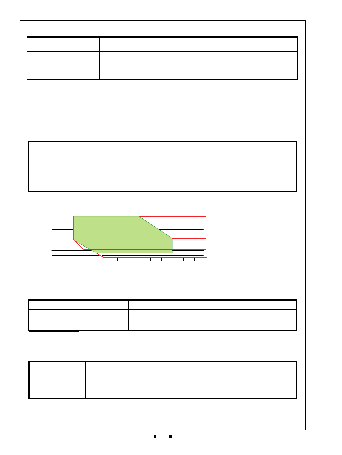
100
90
80
70
60
50
40
30
20
10
0
0 5 10 15 20 25 30 35 40 45 50 55 60
Hydrothermal Condition Table
Humidity [%RH]
Allowable
and Humidity Range
35ºC/85RH%
50ºC/40RH%
Operating Temperature
15ºC/15RH%
5ºC/40RH%
Temperature [°C]
Table 5 RT/RQ Technical Specifications (Continued)
Recycler Capacity
***
:
RT Unit: Max. 60 Notes (Max. 30 Notes x 2 Drums)
RQ Unit: Max. 120 Notes (Max. 30 Notes x 4 Drums)
USB (USB Specification Rev. 2.0 Compliance) (Full Speed/12Mbps)
Interfaces:
Photo-Coupler Isolation
RS232C
cc-Talk
*. The Banknotes accepted on the second attempt are included. The Acceptance Rate Test was conducted on more than 100 Banknotes. Refer to the “Software Information
Sheet” for each Country’s Acceptance Rate parameters.
†. Refer to the specific Country’s Barcode Ticket Specification for more details.
‡. Excludes the time lag associated with Host Communication (Power Supply: +24V DC, Temperature: 25º C ±5º C).
**. The average per note when 10 notes are inserted.
††.A key and lock are not included (A tang is provided). Refer to “Cash Box Lock Installation” on page 10 for the installation. (2 Key Hole Caps are fitted in place to cover existing
holes when shipped).
‡‡.The number of Polymer Banknotes stacked depends on the Banknote’s condition and denomination.
***.150mm New Banknote Only
Environmental Specifications
Table 6 RT/RQ Environmental Specifications
Operating Temperature: 5ºC to +50ºC (41ºF to 122ºF) *Depends on hydrothermal conditions
Storage Temperature: -20ºC to +60ºC (-4ºF to 140ºF) *Depends on hydrothermal conditions
Relative Operating Humidity: 15% to 85% RH (non-condensing)
Relative Storage Humidity: 30% to 85% RH (non-condensing)
Visible Light Sensitivity: Avoid contact with direct Sunlight
Installation: Indoors Only
Electrical Specifications
*
Supply Voltage†:
Current Consumption:
*. Measured on a new and factory default RQ Unit.
†. Use a Limited Power Source.
Table 7 RT/RQ Electrical Specifications
24V DC (±5%) (6A or higher Recommended)
Standby: 0.4A
Operation: 2.0A
Peak: 3.8A
Structural Specifications
Table 8 RT/RQ Structural Specifications
Weight Empty:
Mounting:
Outside Dimensions: Refer to “Unit Dimensions” on page 39 of this Service Manual Section.
P/N 960-000209R_Rev. A © 2019, JAPAN CASH MACHINE CO., LTD.
RT (with SH2 Box): 8kg (17.63lbs)
RQ (with SH2 Box): 11.4kg (25.13lbs)
Horizontal, 0 degrees, ±0 degrees angle
(Stacking Up (SU) installation is available. Refer to “Installation Procedure” on page 9.)
Page 19

9
Installation UBA Pro RT/RQ™ Series Banknote Recycler Section 3
3 INSTALLATION
NOTE: Do Not exert external pressure
on the UBA Pro Unit. Strong pressure
on the Unit may cause the Unit‘s
performance to degrade.
NOTE: Ensure that there is sufficient
space to open, clean and maintain a UBA
Pro Unit. (Refer to “Unit Dimensions” on
page 39).
Caution: Be sure to use specified Screw
Holes when installing the Unit.
Caution: To keep the Unit’ performance
optimal, ensure that the mounting
location is horizontally at 0 degrees on a
flat surface and strong enough to
ensure the Unit weight.
Caution: Be sure to connect the Frame
Housing to the Frame Ground of the
Host Machine.
NOTE: Prepare the following Grounding
Wire, Screw and Washer for grounding:
• Grounding Cable with Conductor Diameter
1.6mm or lager
• M4 W Washer (Large) Pan Head, Iron/
Chromium (III), 12mm or shorter
• Toothed Washer
• Tightening Torque: 120N·cm
NOTE: Refer to “Unit Dimensions” on
page 39) for each Frame Ground
location.
Figure 5 Grounding
Figure 5 Grounding
Edge Side
Round
Side
a
b
c
d
NOTE: Prepare the following Screw:
• M4 Screw (the length of each M4 Screw
should not extend more than 6mm long
from the inside of the Frame)
• Tightening Torque: 120N·cm
Figure 6 Side Installation (Standard and SU
Figure 6 Side Installation (Standard and SU
Installation Types)
a
1
a
2
a
3
a
4
a
5
a
6
a
7
a
8
a
1
a
2
a
3
a
4
a
5
a
6
a
7
a
8
SH2 Box Frame Large Box Frame
This section provides installation and operating
instructions for the UBA Pro RT/RQ™ Series
Banknote Recycler (RT/RQ). The information
within contains the following features:
• Installation Procedure
• Cable Interconnection
• DIP Switch Configuration
• LED Flashing Patterns
Installation Procedure
Holes are provided in each Frame Unit to accommodate mounting the RT/RQ Unit
tion. Select and perform the following steps
required to install the RT/RQ Unit.
during installa-
Grounding
1. Install the Toothed Washer (Figure 5 a), the
Grounding Wire (Figure 5 b) and then the Screw
(Figure 5 c) into the Frame Ground (Figure 5 d)
in order.
2. Tighten the Screw to secure the Wire and Washer.
P/N 960-000209R_Rev. A © 2019, JAPAN CASH MACHINE CO., LTD.
Side Installation (For Standard and Stacking Up (SU) Installation types)
When a side mounting configuration is preferred, per-
form the following procedure:
1. Secure the left and right side of the RT/RQ Frame
into its intended location using 8 (eight) M4
Screws from each side of the Frame (Figure 6 a
through a
).
8
1
Page 20

10
Section 3 UBA Pro RT/RQ™ Series Banknote Recycler Installation
Caution: This installation is allowed only
when the RT/RQ unit is used as Standard
installation.
NOTE: Prepare the following Screw:
• From Inside: M4 Screw
• From Outside: φ4 Stud (the maximum length
of each Stud should not extend more than
10mm long from the inside of the Bottom
Frame
• Tightening Torque: 120N·cm
Figure 7 Bottom Installation (Standard Installa-
Figure 7 Bottom Installation (Standard Installation
Type)
a
1
a
2
a
3
a
4
b
1
b
2
b
3
b
4
NOTE: Prepare the following Screw:
• M3x16 Screw (provided)
• Tightening Torque: 60N·cm
Figure 8 Bezel Installation
Figure 8 Bezel Installation
b
1
a
b
2
NOTE: Prepare the following Screw:
• M3x12 Screw (provided)
• Tightening Torque: 80N·cm
Figure 9 External Harness Installation
Figure 9 External Harness Installation
d
1
d
2
a
b
c
Figure 10 Key Hole Location
Figure 10 Key Hole Location
Key Holes
Bottom Installation (For Standard Installation Type Only)
When a bottom mounting configuration is preferred,
perform the following procedure:
1. From Inside:
Secure the inside of the RT/RQ Bottom Frame
into its intended location using four (4) M4
Screws (Figure 7 a
From Outside:
Secure the outside of the RT/RQ Bottom Frame
into its intended location using the four (4)
threaded φ4 Studs (Figure 7 b
through a4).
1
1
through b4).
External Harness Installation
1. Pug in the Power Cable (Figure 9 a) and the
Interface Harness (Figure 9 b) into each Connector.
2. Secure the Connector (Figure 9 c) using two (2)
specified Screws (Figure 9 d
& d2).
1
Bezel Installation
1. Secure the Bezel (Figure 8 a) using two (2) specified Screws (Figure 8 b
& b2).
1
P/N 960-000209R_Rev. A © 2019, JAPAN CASH MACHINE CO., LTD.
Cash Box Lock Installation
One or two security locks can be installed onto a
Cash Box. When installing a security lock, the following attachment accessories may be required:
• Two Key Spacers
• Plate Lock Keys
• Key Cap Attachment.
Page 21

11
Installation UBA Pro RT/RQ™ Series Banknote Recycler Section 3
Figure 11 Key Hole Dimension & Cylinder
Length
Figure 11 Key Hole Dimension & Cylinder Length
Ø
1
9
.
1
16.1 mm
1
-1
/
8
i
n
.
5
/
8
i
n
.
2
0
.5
m
m
NOTE: When two locks are installed, they
must rotate in the same direction as
illustrated in Figure 12.
Figure 12 Key Lock Rotation Requirement
Figure 12 Key Lock Rotation Requirement
Unlock
Unlock
5/8” or 1-1/8” hole
20.5mm hole
NOTE: When using only one lock, the
remaining blank hole does not provide
access to Cash Box contents. However,
some regulatory authorities may require
installation of a Key Cap.
Figure 13 Key Cap Installation
Figure 13 Key Cap Installation
Use Key Cap
NOTE: There are many lock designs, and
Key Spacer washers may be required for
some lock types. Locks vary greatly in price,
security, keying policies, et cetera. The
customer is responsible for selecting a Lock
with performance that fits the intended
purpose. JCM does not test or endorse
any
specific brand of Lock for its security
characteristics.
NOTE: Front DIP Switch settings may vary
based on Software. Refer to each Country’s
“Software Information Sheet” for making the
proper switch settings.
ON
OFF
NOTE: Refer to the UBA Pro RC Series
Banknote Recycler Integration Guide for
the Recycler options.
Figure 14 SW1 and SW2 Switches
Figure 14 SW1 and SW2 Switches
SW1
SW2
Bottom View
Choose a Lock that fits a standard 5/8”, 1-1/8” or
20.5mm hole dimension format (Figure 11). In
addition, when two locks are to be installed, both
locks must be identical.
Unlock Procedure
Make sure lock(s) are installed and rotates in the
correct direction(s).
DIP Switch Configurations
Denomination Acceptance Settings (DIP Switches at the front)
Table 9 lists the default Front DIP Switches configurations for the acceptable denominations.
Table 9 Denomination Acceptance Settings
Switch No. Switch ON/OFF Description
1
2
3
4
5
6
7
8
*. Not Applicable (N/A). Never Switched to ON.
ON VEND 1 INHIBIT
OFF VEND 1 ACCEPT
ON
OFF VEND 2 ACCEPT
ON
OFF VEND 3 ACCEPT
ON
OFF VEND 4 ACCEPT
ON
OFF VEND 5 ACCEPT
ON
OFF VEND 6 ACCEPT
ON
OFF VEND 7 ACCEPT
*
OFF
VEND 2 INHIBIT
VEND 3 INHIBIT
VEND 4 INHIBIT
VEND 5 INHIBIT
VEND 6 INHIBIT
VEND 7 INHIBIT
OFF (Fixed)
P/N 960-000209R_Rev. A © 2019, JAPAN CASH MACHINE CO., LTD.
SW1 and SW2 Configurations
The UBA Pro CPU Circuit Board contains two (2)
DIP Switches that are located adjacent to one
another. The interface and the Recycler option can
be configured by these Switches (Figure 14).
Page 22

12
Section 3 UBA Pro RT/RQ™ Series Banknote Recycler Installation
NOTE: For the USB interface, no need to
configure the SW1 switch.
SW 1
SW 2
Front
Back
Interface and Recycler Settings (Sub Board 2)
The SW1 switch equipped on the Sub Board 2 is to
set an interface RS232C, Photo-Coupler Isolation,
or ccTalk (Table 10).
Table 10 Sub Board 2 Interface Settings
Settings Description
Photo-Coupler Isolation
SW1
-
RS232C
cc-Talk
USB
To use a UBA Pro Unit
with a Recycler Unit(s)
SW2
To use a UBA Pro Unit
without a Recycler(s)
*. Refer to the UBA Pro Series Operation and Maintenance Manual for using the
UBA Pro unit with a Recycler(s).
*
P/N 960-000209R_Rev. A © 2019, JAPAN CASH MACHINE CO., LTD.
Page 23

Installation UBA Pro RT/RQ™ Series Banknote Recycler Section 3
13
NOTE: Refer to “LED Error Codes” on page 36 for a detailed explanation of each error code.
OFF
OFF
OFF
OFF
ON
ONONON
Status LED
OFF
Cyan Flashes
White ON
Blue Flashes
Green ON
Yellow Flashes
White Flashes
Red Flashes
Green Flashes
Green ↔ Red
Flashes
Magenta Flashes
LED Flashing Patterns
The LED Color Pattern indications listed in Table 11 and Table 12 occur during various RT/RQ Unit operating and error conditions.
Table 11 Recycler and Transport LEDs Flashing Patterns
Recycler LED Cause and Solution Transport LED Cause and Solution
Operating Operating
Operating Operating
Error occurred in a Drum of the RT
Transport side.
Error occurred in a Drum of the RQ
Transport side.
Error occurred in the RT Transport side.
Error occurred in the RQ Transport side.
Table 12 Status LED Flashing Patterns
Status LED Cause and Solution Status LED Cause and Solution
Stand-by (Test Mode)/Operating
or
Error occurred in the UBA Pro Unit.
(Refer to the UBA Pro Series Universal
Banknote Acceptor Integration Guide
for the UBA Pro Unit’s details.)
Turning power on
Stand-by (Normal Mode)
Error occurred while a Banknote
was being dispensed.
Return the cash in the RT/RQ Unit.
Error occurred after a Banknote
was determined to dispense.
Return the cash to the customer.
Error occurred while a Banknote
was being accepted.
Return the cash to the customer.
Error occurred while turning power on.
Error occurred when the Unit was in
stand-by.
Error occurred when Banknotes were
being collected.
P/N 960-000209R_Rev. A © 2019, JAPAN CASH MACHINE CO., LTD.
Error occurred after a Banknote
was determined to accept.
Return the cash in the RT/RQ Unit.
Downloading softer from Acceptor
Head Unit to Recycler.
Page 24

Section 4 UBA Pro RT/RQ™ Series Banknote Recycler Connector Pin Assignments
14
4 CONNECTOR PIN ASSIGNMENTS
This section provides the pin assignments of the UBA Pro RT/RQ™ Series Banknote Recycler (RT/RQ).
The information within contains the following features:
• USB Interface Connector Pin Assignments (UBA Pro Side)
• Photo Coupler Interface Connector Pin Assignments (UBA Pro Side)
• RS232C Interface Connector Pin Assignments (UBA Pro Side)
• cc-Talk Interface Connector Pin Assignments (UBA Pro Side)
• Power Supply Connector Pin Assignments (RT/RQ Side)
• Interface Connector Pin Assignments (RT/RQ Side)
• Bezel Connector Pin Assignments (UBA Pro Side)
USB Interface Connector Pin Assignments (UBA Pro Side)
Table 13 USB Interface Connector Pin Assignments (UBA Pro Side)
Socket (UBA Pro Unit Side): DRA-20PC-FO (JAE)
Contact (UBA Pro Unit Side): D02-22-26P-10000 (JAE)
Socket (Frame Side): DRA-20SC-FO (JAE)
Contact (Frame Side): D02-22-26S-10000 (JAE)
Contact (Frame Side) Pin No.3, No.13: D02-22-22S-10000 (JAE)
Recommended Wires: Slit Wire UL1061 AWG #26
Pin No. Signal Name
1 - - Reserved (For the UBA Pro Side)
2 - - Reserved (For the UBA Pro Side)
3 M.RES IN Acceptor Reset Signal Line
4 NC - No Connection
5 - - Reserved (For the UBA Pro Side)
6 NC - No Connection
7 NC - No Connection
8 Vbus IN USB Communication Vbus Signal Line (+5V DC)
9 -DATA IN/OUT USB Communication Input/Output Signal Line
10 +DATA IN/OUT USB Communication Input/Output Signal Line
11 - - Reserved (For the UBA Pro Side)
12 GND (USB) - USB Communication Ground (0V DC)
13 NC - No Connection
14 LED POWER - LED Drive Line (Anode)
15 - - Reserved (For the UBA Pro Side)
16 NC - No Connection
17 - - Reserved (For the UBA Pro Side)
18 LED - - LED Drive Line (Cathode)
19 NC - No Connection
20 - - Reserved (For the UBA Pro Side)
*. I/O (input/output) is the terminal as viewed from the RT/RQ Unit’s side.
I/O
*
Function
P/N 960-000209R_Rev. A © 2019, JAPAN CASH MACHINE CO., LTD.
Page 25

Connector Pin Assignments UBA Pro RT/RQ™ Series Banknote Recycler Section 4
15
NOTE: The Interface setup is required. Refer to “Interface and Recycler Settings (Sub Board 2)” on
page 12 for the settings.
Photo Coupler Interface Connector Pin Assignments (UBA Pro Side)
Table 14 Photo Coupler Interface Connector Pin Assignments (UBA Pro Side)
Socket (UBA Pro Unit Side): DRA-20PC-FO (JAE)
Contact (UBA Pro Unit Side): D02-22-26P-10000 (JAE)
Socket (Frame Side): DRA-20SC-FO (JAE)
Contact (Frame Side): D02-22-26S-10000 (JAE)
Contact (Frame Side) Pin No.3, No.13: D02-22-22S-10000 (JAE)
Recommended Wires: Slit Wire UL1061 AWG #26
Pin No. Signal Name
I/O
*
Function
1 - - Reserved (For the UBA Pro Side)
2 - - Reserved (For the UBA Pro Side)
3 M.RES IN Acceptor Hard Reset Signal Line
4 TXD OUT Output Signal Line from Acceptor to Host
5 - - Reserved (For the UBA Pro Side)
6 RXD IN Input Signal Line from Host to Acceptor
7 GND (I/F) - Interface Power Supply (Photo Coupler 0V DC)
8 NC - No Connection
9 NC - No Connection
10 NC - No Connection
11 - - Reserved (For the UBA Pro Side)
12 NC - No Connection
13 NC - No Connection
14 LED POWER - LED Indicator Power Supply Line (Anode)
15 - - Reserved (For the UBA Pro Side)
16 NC - No Connection
17 - - Reserved (For the UBA Pro Side)
18 LED - LED Indicator Control Line (Cathode)
19 NC - No Connection
20 - - Reserved (For the UBA Pro Side)
*. I/O (input/output) is the terminal as viewed from the RT/RQ Unit’s side.
P/N 960-000209R_Rev. A © 2019, JAPAN CASH MACHINE CO., LTD.
Page 26

Section 4 UBA Pro RT/RQ™ Series Banknote Recycler Connector Pin Assignments
16
NOTE: The Interface setup is required. Refer to “Interface and Recycler Settings (Sub Board 2)” on
page 12 for the settings.
RS232C Interface Connector Pin Assignments (UBA Pro Side)
Table 15 RS232C Connector Pin Assignments (UBA Pro Side)
Socket (UBA Pro Unit Side): DRA-20PC-FO (JAE)
Contact (UBA Pro Unit Side): D02-22-26P-10000 (JAE)
Socket (Frame Side): DRA-20SC-FO (JAE)
Contact (Frame Side): D02-22-26S-10000 (JAE)
Contact (Frame Side) Pin No.3, No.13: D02-22-22S-10000 (JAE)
Recommended Wires: Slit Wire UL1061 AWG #26
Pin No. Signal Name
I/O
*
Function
1 - - Reserved (For the UBA Pro Side)
2 - - Reserved (For the UBA Pro Side)
3 M.RES IN Acceptor Hard Reset Signal Line
4 TXD OUT Output Signal Line from Acceptor to Host
5 - - Reserved (For the UBA Pro Side)
6 RXD IN Input Signal Line from Host to Acceptor
7 NC - No Connection
8 NC - No Connection
9 NC - No Connection
10 NC - No Connection
11 - - Reserved (For the UBA Pro Side)
12 NC - No Connection
13 GND (I/F) - Interface Power Supply (RS232C 0V DC)
14 LED POWER - LED Indicator Power Supply Line (Anode)
15 - - Reserved (For the UBA Pro Side)
16 NC - No Connection
17 - - Reserved (For the UBA Pro Side)
18 LED - LED Indicator Control Line (Cathode)
19 NC - No Connection
20 - - Reserved (For the UBA Pro Side)
*. I/O (input/output) is the terminal as viewed from the RT/RQ Unit’s side.
P/N 960-000209R_Rev. A © 2019, JAPAN CASH MACHINE CO., LTD.
Page 27

Connector Pin Assignments UBA Pro RT/RQ™ Series Banknote Recycler Section 4
17
NOTE: The Interface setup is required. Refer to “Interface and Recycler Settings (Sub Board 2)” on
page 12 for the settings.
cc-Talk Interface Connector Pin Assignments (UBA Pro Side)
Table 16 cc-Talk Interface Connector Pin Assignments (UBA Pro Side)
Socket (UBA Pro Unit Side): DRA-20PC-FO (JAE)
Contact (UBA Pro Unit Side): D02-22-26P-10000 (JAE)
Socket (Frame Side): DRA-20SC-FO (JAE)
Contact (Frame Side): D02-22-26S-10000 (JAE)
Contact (Frame Side) Pin No.3, No.13: D02-22-22S-10000 (JAE)
Recommended Wires: Slit Wire UL1061 AWG #26
Pin No. Signal Name
I/O
*
Function
1 - - Reserved (For the UBA Pro Side)
2 - - Reserved (For the UBA Pro Side)
3 M.RES IN Acceptor Hard Reset Signal Line
4 NC - No Connection
5 - - Reserved (For the UBA Pro Side)
6 NC - No Connection
7 NC - No Connection
8 NC - No Connection
9 NC - No Connection
10 NC - No Connection
11 - - Reserved (For the UBA Pro Side)
12 NC - No Connection
13 GND (I/F) - Interface Power Supply (cc-Talk 0V DC)
14 LED POWER - LED Indicator Power Supply Line (Anode)
15 - - Reserved (For the UBA Pro Side)
16 TXD OUT Output Signal Line from Acceptor to Host
17 - - Reserved (For the UBA Pro Side)
18 LED - LED Indicator Control Line (Cathode)
19 NC - No Connection
20 - - Reserved (For the UBA Pro Side)
*. I/O (input/output) is the terminal as viewed from the RT/RQ Unit’s side.
P/N 960-000209R_Rev. A © 2019, JAPAN CASH MACHINE CO., LTD.
Page 28

Section 4 UBA Pro RT/RQ™ Series Banknote Recycler Connector Pin Assignments
18
413
2
143257
86
9
10
Power Supply Connector Pin Assignments (RT/RQ Side)
Table 17 Power Supply Connector Pin Assignments (RT/RQ Side)
Header Type: 43045-0424 (MOLEX)
Contact Type: 43030-0001 (MOLEX)
Housing: 43025-0400 (MOLEX)
Recommended Wires: Slit Wire UL1007 AWG #20-24
Pin No. Signal Name I/O Function
1 VHOST24V - +24V DC Power Supply
2 NC - No Connection
3 PGND - 0V DC Power Supply
4 NC - No Connection
Interface Connector Pin Assignments (RT/RQ Side)
Table 18 Interface Connector Pin Assignments (RT/RQ Side)
Header Type: B10B-PADSS-1 (JST)
Contact Type: SPH-002T-P0.5L (JST)
Housing: PADP-10V-1-S (JST)
Recommended Wires: Slit Wire UL1061 AWG #22-28
Pin No. Signal Name I/O Function
1 - - Reserved (The pin is used on the UBA Pro Side)
2 - - Reserved (The pin is used on the UBA Pro Side)
3 - - Reserved (The pin is used on the UBA Pro Side)
4 - - Reserved (The pin is used on the UBA Pro Side)
5 - - Reserved (The pin is used on the UBA Pro Side)
6 - - Reserved (The pin is used on the UBA Pro Side)
7 - - Reserved (The pin is used on the UBA Pro Side)
8 - - Reserved (The pin is used on the UBA Pro Side
9 - - Reserved (The pin is used on the UBA Pro Side)
10 NC - No Connection
Bezel Connector Pin Assignments (UBA Pro Side)
Table 19 Bezel Connector Pin Assignments (UBA Pro Side)
Header Type: RF-H08(07)2SD-1110 (JST)
Contact Type: RF-SC2210 (JST)
Housing: RF-08 (JST)
Recommended Wires: Slit Wire UL1007 AWG #24-26
Pin No. Signal Name
1 NC - No Connection
2 NC - No Connection
3 NC - No Connection
4 NC - No Connection
5 +13V (Power) - +13V DC Power (from UBA Pro)
6 GND (Power) - 0V DC Power (from UBA Pro)
7 LED Power - LED Drive Line (Anode)
8 LED- - LED Drive Line (Cathode)
*. I/O (input/output) is the terminal as viewed from the RT/RQ Unit’s side.
I/O
*
Function
P/N 960-000209R_Rev. A © 2019, JAPAN CASH MACHINE CO., LTD.
Page 29

19
Preventive Maintenance UBA Pro RT/RQ™ Series Banknote Recycler Section 5
5 PREVENTIVE MAINTENANCE
NOTE: Do Not manually refill the
Banknotes directly into the Recyclers.
Figure 15 Refilling Banknotes
Figure 15 Refilling Banknotes
NOTE: Enable the Collect Button function
by sending a Command from the Host
Machine (disabled by default).
NOTE: The Banknotes in each Drum
will be transported note-by-note into
the Cash Box.
Figure 16 Collecting Banknotes 1
Figure 16 Collecting Banknotes 1
a
Figure 17 Collecting Banknotes 2
Figure 17 Collecting Banknotes 2
a
b
c
NOTE: The Banknotes in each Drum
will be transported note-by-note into
the Cash Box.
NOTE: Before setting the Recycler’s
denomination values, check the Banknote
sizes against the Recycler’s size limitation
settings (refer to “Technical Specifications”
on page 7). This operation should be
performed once appropriate Operator
training has been completed.
This section provides the preventive maintenance
for the UBA Pro RT/RQ™ Series Banknote Recycler (RT/RQ). It includes the following information:
• Refilling Banknotes
• Collecting Banknotes
• Clearing a Banknote Jam
• Cleaning Procedures
Refilling Banknotes
Banknotes can be refilled into the Recycler by
using the UBA Pro Unit.
To refill Banknotes into the Recycler, perform the
following procedure:
1. Insert Banknotes note-by-note in a single fashion
into the Insertion Slot or Bezel (Figure 15).
2. Remove the Cash Box (Figure 17 a).
3. Use the appropriate User-supplied Key(s) to
unlock the Cash Box (Figure 17 b).
4. Open the Cash Box Door and remove the collected Banknotes (Figure 17 c).
Collecting Banknotes
To collect Banknotes from the Recycler, perform
one (1) of the following two (2) procedures.
Collecting Banknotes into the Cash Box by the Button
1. Press the Collect Button on the RT/RQ Unit (Figure 16 a).
Collecting Banknotes into the Cash Box by Command
1. Send a Command to the RT/RQ Unit from the
Host Machine in order to collect Banknotes.
2. Remove the Cash Box (Figure 17 a).
3. Use the appropriate User-supplied Key(s) to
unlock the Cash Box (Figure 17 b).
4. Open the Cash Box Door and remove the collected Banknotes (Figure 17 c).
Dispense Settings
Dispensing Banknotes from each Drum of the
Recycler to the Insertion Slot or the Bezel is possible. Banknote denomination dispensing is predetermined by settings made for each Drum.
To change the dispensable Banknote denomination
values, replace the Recycler with another Unit containing the different denomination settings.
P/N 960-000209R_Rev. A © 2019, JAPAN CASH MACHINE CO., LTD.
Page 30

20
Section 5 UBA Pro RT/RQ™ Series Banknote Recycler Preventive Maintenance
NOTE: Do Not re-insert a removed
Banknote caused by Banknote Jam or
error.
NOTE: Refer to the UBA Pro Series
Universal Banknote Acceptor
Integration Guide for the UBA Pro
Unit’s details.
Figure 18 UBA Pro Unit Banknote Jam Clear
Figure 18 UBA Pro Unit Banknote Jam Clear
a
b
Figure 19 RT Transport Banknote Jam Clear 1
Figure 19 RT Transport Banknote Jam Clear 1
a
Figure 20 RT Transport Banknote Jam Clear 2
Figure 20 RT Transport Banknote Jam Clear 2
b
c
a
Figure 21 RT Transport Banknote Jam Clear 3
Figure 21 RT Transport Banknote Jam Clear 3
a
b
c
Figure 22 RT Transport Banknote Jam Clear 4
Figure 22 RT Transport Banknote Jam Clear 4
a
b
Clearing a Banknote Jam
Find where a Banknote Jam occurred
Check each LED to determine where and/or in
which Unit a Banknote is jammed (refer to “LED
Error Codes” on page 36).
Jammed in UBA Pro Unit
To remove jammed Banknotes from the UBA Pro
Unit, proceed as follows to clear it.
1. Lift up on the Upper Guide Access Lever to open
the UBA Pro’s Cover (Figure 18 a).
2. Remove any jammed Banknote found there. (Figure 18 b).
3. Remove any jammed Banknote found there (Figure 20 c).
4. If the Banknote jam location is not visible, press
down on the Front Transport Unit’s Release
Lever (Figure 21 a) to pull up the Front Transport
Unit (Figure 21 b).
5. Remove any jammed Banknote found there (Figure 21 c).
Jammed in RT Transport Banknote
To remove jammed Banknotes from the RT Transport, proceed as follows to clear it.
1. Unlock the Recycler Release Lock (Figure 19 a).
6. If the Banknote jam location is not visible, pull
and release the Transport Unit’s Release Lever
(Figure 22 a) to lift the Transport Unit (Figure 22
b).
2. Press down on the Release Lever (Figure 20 a) of
P/N 960-000209R_Rev. A © 2019, JAPAN CASH MACHINE CO., LTD.
the Recycler installed in the RT Transport to
remove the Recycler (Figure 20 b) out of the RT
Transport.
7. Remove the Transport Unit out of the RT Transport (Figure 23 a).
Page 31

21
Preventive Maintenance UBA Pro RT/RQ™ Series Banknote Recycler Section 5
Figure 23 RT Transport Banknote Jam Clear 5
Figure 23 RT Transport Banknote Jam Clear 5
a
b
Figure 24 RQ Transport Banknote Jam Clear 1
Figure 24 RQ Transport Banknote Jam Clear 1
a
Figure 25 RQ Transport Banknote Jam Clear 2
Figure 25 RQ Transport Banknote Jam Clear 2
b
c
a
Figure 26 RQ Transport Banknote Jam Clear 3
Figure 26 RQ Transport Banknote Jam Clear 3
b
c
a
Figure 27 RQ Transport Banknote Jam Clear 4
Figure 27 RQ Transport Banknote Jam Clear 4
b
a
Figure 28 RQ Transport Banknote Jam Clear 5
Figure 28 RQ Transport Banknote Jam Clear 5
a
b
8. Remove any jammed Banknote found there (Figure 23 b).
Jammed in RQ Transport
To remove jammed Banknotes from the RQ Transport, proceed as follows to clear it.
1. Unlock the Recycler Release Lock (Figure 24 a).
5. Remove any jammed Banknote found there (Figure 26 c).
6. If the Banknote jam location is not visible, press
down on the Transport Unit’s Lever (Figure 27 a)
to pull down the Transport Unit (Figure 27 b).
2. Press up on the Release Lever (Figure 25 a) of
the Recycler installed in the RQ Transport to
remove the Recycler (Figure 25 b) out of the RQ
Transport.
3. Remove any jammed Banknote found there (Figure 25 c).
4. If the Banknote jam location is not visible, press
P/N 960-000209R_Rev. A © 2019, JAPAN CASH MACHINE CO., LTD.
up on the Front Transport Unit’s Lever (Figure 26
a) to pull down the Front Transport Unit (Figure
26 b).
7. Remove the Transport Unit (Figure 28 a).
8. Remove any jammed Banknote found there (Figure 28 b).
Page 32

22
Section 5 UBA Pro RT/RQ™ Series Banknote Recycler Preventive Maintenance
NOTE: Be sure to send a command and
update the number of Banknotes in the
Recycler(s) after removing a jammed
Banknote in order to maintain the
Banknote count match.
Figure 29 Recycler Drum Banknote Jam Clear 1
Figure 29 Recycler Drum Banknote
Jam Clear 1
a
Figure 30 Recycler Drum Banknote Jam Clear 2
Figure 30 Recycler Drum Banknote
Jam Clear 2
a
RT Transport
RQ Transport
b
b
b
NOTE: Do Not manually rotate any Drum
when there is no Banknote to avoid the
risk of damage to the Recycler.
NOTE: Do Not put a tool directly inside
of the Recycler to remove a jammed
Banknote. A winded film may be pulled
out resulting in damage to the Recycler.
Figure 31 Recycler Drum Banknote Jam Clear 3
Figure 31 Recycler Drum Banknote
Jam Clear 3
b
6mm Hex
a
Nut Driver
Figure 32 Cash Box Banknote Jam Clear
Figure 32 Cash Box Banknote Jam Clear
a
b
NOTE: Performing specified routine
cleaning at least once a month is required to
maintain optimal performance.
NOTE: Refer to the UBA Pro Series
Universal Banknote Acceptor
Integration Guide for the UBA Pro
Unit’s details.
Jammed in Recycler Drum
To remove jammed Banknotes from the Recycler
Drum, proceed as follows to clear it.
1. Unlock the Recycler Release Lock (Figure 29 a).
Jammed in Cash Box
To remove jammed Banknotes from the Cash Box,
proceed as follows to clear it.
1. Pull the Cash Box (Figure 32 a) out of the Frame.
2. Remove any jammed Banknote found there (Figure 32 b).
2. Release the Release Lever (Figure 30 a) of the
desired Recycler to remove the desired Recycler
(Figure 30 b) out of the Frame.
3. Flip the Recycler.
4. Use a 6mm Hex Nut Driver to rotate the desired
Drum Shaft (Figure 31 a) in the dispense direction indicated by the arrow.
5. Remove the jammed Banknote (Figure 31 b).
P/N 960-000209R_Rev. A © 2019, JAPAN CASH MACHINE CO., LTD.
Cleaning Procedure
To clean the RT/RQ Unit Banknote path, gently rub
the Sensors and Rollers using a dry, soft, lint-free,
Micro-fiber Cloth ONLY.
Sensor Cleaning Procedure
Perform the following steps to clean the UBA Pro
and RT/RQ Unit’s Sensors:
1. Remove electrical power from the RT/RQ Unit.
2. Open the UBA Pro Unit’s Cover.
3. Clean the Sensor Lens and Rollers in the
Banknote Path.
4. Pull the Recycler out of the RT/RQ Frame.
5. Clean the Sensor Lenses, Roller and Belts located
in the RT/RQ Frame, Recycler and/or Cash Box.
Page 33

Preventive Maintenance UBA Pro RT/RQ™ Series Banknote Recycler Section 5
23
Caution: DO NOT use alcohol, solvents,
abrasive cleaning agents, or citrusbased cleaners that can damage the
plastic surface of the device when
cleaning it. The lenses can become
clouded by chemical evaporation
residue that may cause acceptance
errors.
Caution: Be sure to use non-flammable
compressed air only.
Caution: DO NOT let liquids or fluids
drip into the Unit’s interior; otherwise,
the Unit may not operate correctly.
NOTE: When closing or installing the UBA
Pro Unit or the Recycler, ensure it firmly
clicks into place. Also, when re-assembling
the RT/RQ Unit, ensure that it re-seats
correctly into place when reassembly is
complete.
NOTE: Wipe and clean all of the Green-
colored Rollers and Belts shown in Figure
34 on page 24 using a slightly damp (not
wet), lint-free Micro-fiber cloth.
NOTE: Cleaning the Pick Roller should be
performed only when appropriate Operator
training has been completed!
Figure 33 Sensor and Roller Cleaning
Figure 33 Sensor and Roller Cleaning
Lens
Roller
Lint-free Cloth/Cotton Swab/Air
Before
Cleaning
After
Cleaning
Belt
P/N 960-000209R_Rev. A © 2019, JAPAN CASH MACHINE CO., LTD.
Page 34

Section 5 UBA Pro RT/RQ™ Series Banknote Recycler Preventive Maintenance
24
Figure 34 RT/RQ Sensor, Roller and Belt Clean-
ing Locations
Figure 34 RT/RQ Sensor, Roller and Belt Cleaning Locations
2
1
D
F
E
RQ Unit
H
6
5
4
Recycler
A
or
D
B or E
C or F
NOTE: Refer to the UBA Pro Series Universal Banknote Acceptor Operation and Maintenance
Manual for the UBA Pro Unit’s sensor locations.
RT Unit
C
A
B
H
1
2
3
1
2
3
4
5
6
B
A
C
B
A
A
C
D
E
F
D
E
F
D
I
I
I
2
1
G
Sensor, Roller and Belt Cleaning Locations
Figure 34 illustrates the various RT/RQ Unit’s sensor and roller cleaning locations.
P/N 960-000209R_Rev. A © 2019, JAPAN CASH MACHINE CO., LTD.
Page 35

Preventive Maintenance UBA Pro RT/RQ™ Series Banknote Recycler Section 5
25
NOTE: Wipe and clean all of the Green colored Rollers and Belts shown in Figure 34 using a
slightly damp, lint-free, Micro-fiber cloth. Do not allow liquids or fluids to drip into the Unit, to
minimize the risk of damage or improper performance.
Table 20 RT/RQ Sensor Cleaning Methods
Sym. Sensors Cleaning Method
A Note Position Sensor A (RT Transport)
B Note Position Sensor B (RT Transport)
C Note Position Sensor C (RT Transport)
Wipe clean using a dry lint free cloth/cotton swab
D Note Position Sensor D (RQ Transport)
E Note Position Sensor E (RQ Transport)
F Note Position Sensor F (RQ Transport)
Drum 1 Tape Full Empty Sensor 1
1
G
(RT/RQ Transport)
Drum 2 Tape Full Empty Sensor 2
2
(RT/RQ Transport)
Clean using non-flammable Compressed Air
H Exit Prism Wipe clean using a dry lint free cloth/cotton swab
1 Note Position Sensor 1 (RT Transport)
2 Note Position Sensor 2 (RT Transport)
Note Position Sensor 3 (RT Transport)
3
I
*This sensor is not visible.
Wipe clean using a dry lint free cloth/cotton swab
Clean using non-flammable Compressed Air
4 Note Position Sensor 4 (RQ Transport)
Wipe clean using a dry lint free cloth/cotton swab5 Note Position Sensor 5 (RQ Transport)
6 Note Position Sensor 6 (RQ Transport)
P/N 960-000209R_Rev. A © 2019, JAPAN CASH MACHINE CO., LTD.
Page 36

Section 5 UBA Pro RT/RQ™ Series Banknote Recycler Preventive Maintenance
26
THIS PAGE INTENTIONALLY LEFT BLANK
P/N 960-000209R_Rev. A © 2019, JAPAN CASH MACHINE CO., LTD.
Page 37

27
Figure 35 Bezel Connector Interface Circuit
Schematics
Figure 35 Bezel Connector Interface Circuit Schematics
N.C
N.C
12V
12V
N.C
N.C
O-TTL3(TXD0)
PW GND
LED POWER LED POWER
GND
220Ω
LED LED
1
2
3
4
7
8
DC5V
4R7K
DC12V
D12V
I-TTL3(port4)
N.C
N.C
PW GND
5
6
GND
DC5V
GND
UMH3N
100Ω
GND
DC3.3V
GND
UMH3N
DC3.3V
100Ω
1
2
3
4
7
8
5
6
Host Machine (Reference)
UBA Pro
Standard Interface Circuit Schematics UBA Pro RT/RQ™ Series Banknote Recycler Section 6
6 STANDARD INTERFACE CIRCUIT SCHEMATICS
This section provides the interface circuit schematics of the UBA Pro RT/RQ™ Series Banknote Recycler (RT/RQ).
Bezel Connector Interface Circuit Schematics
P/N 960-000209R_Rev. A © 2019, JAPAN CASH MACHINE CO., LTD.
Page 38

28
Figure 36 RT/RQ Interface Circuit Schematics
(Sub Board 2)
Figure 36 RT/RQ Interface Circuit Schematics (Sub Board 2)
POWER(VIN)
GND (VIN )
M-RESET
DC24V
POWER(VIN)
GND (VIN )
+12V( I/F)
M-RESET
USB Vbus(user1)
USB DM(user1)
USB DP(user1)
DC5V
GND
D-
D+
USB CONTROLLER
USB Specification
Rev.2.0
Full speed
USB Vbus(user 1)
USB DM(user1)
USB DP(user1)
GND
TLP291
2R2K 1SS352
DC3.3V
GND
GND
33Ω
33Ω
1uF
TPD2E2U06
NYI
GND (USB)
GND
GND (USB)
GND
100Ω
125
3
8910
12
GND
GND
DC24V
Removal C onnector
Opto GND
GND
Opto GND
GND
PC400
DC5V
100pF
4R7K
NYI
DC3.3V
NYI
PC400
DC3.3V
2R2K
1SS352
7
GNDGND
GND
Serial IN
GND
Serial O UT
Serial IN
GND GND
Serial O UT
DOUT
RIN
INVENVCC
V+V-GND
DIN
ROUT
FOFFFON
C1+
C1-
C2+
C2-
DC3.3V
GNDGNDGND
DC3.3V
GNDGNDGND
DC3.3V
DC3.3V
GND
10K
DC3.3V
0.1uF
0.1uF
0.1uF
0.1uF
0.1uF
0.1uF
TPD2E007
4
6
13
GND
GND
GND
CMS-420 2
DOUT
RIN
INVENVCC
V+V-GND
DIN
ROUT
FOFFFON
C1+
C1-
C2+
C2-
DC3.3V
cc-Talk(+) I-TTL2 cc-Talk(+) I-TTL2
16
GND
10K
UMH3N
NYI
1SS352
CUS357
1SS352
4R7K
DC12V
DC12V
GND
DC5V
DC5V
DC5V
GND
GND
GND
GND
GND
DC3.3V
DC5V
I-TTL1
I-TTL3
SS/SU:RC
O-TTL3
O-TTL2
GND
201918
15
17
DC5V
R-5V
220Ω
14
O-TTL1
11
R-5V
O-TTL3
O-TTL1
4R7K×2
100Ω
100Ω×3
1000pF×4
SS/SU RC
GND
UMH3N×4
O-TTL2
RS232CPh oto-C oupl ercc-Talk TTL
USB
Photo- Coupl er
(SW1)
(SW2)
I/F 12V
PGND
VHOST 24V
VHOST 24V
PGND
TXD
RDY
MAIN RESET
MRESET
I/F C onnector
Power Cord
GND
1
3
I/F GND
GND
1
2
VHOST24V
UMH3N
3
IF12V
9
GND
4
5
8
UMH3N
7
10K
TLP291
2R2K
1SS352
DC3.3V
GND
IF12V
10K
RXD
10
Recycler
DC5V
NC
NC
2
4
VHOST24V
1K
DC5V
NC
6
1K×2
100Ω
4R7K
4R7K
1K
GND
0.1uF
GND
4R7K
GND
1000pF
GND
RS23 2C
cc-Talk
Host Machine (Reference)
UBA Pro (with Sub Board 2)
RT/RQ Unit
P/N 960-000209R_Rev. A © 2019, JAPAN CASH MACHINE CO., LTD.
RT/RQ Interface Circuit Schematics (Sub Board 2)
Section 6 UBA Pro RT/RQ™ Series Banknote Recycler Standard Interface Circuit Schematics
Page 39

Operational Flowchart UBA Pro RT/RQ™ Series Banknote Recycler Section 7
29
Figure 37 RT/RQ Main Flow Process
Figure 37 RT/RQ Main Flow Process
a) Initializing
b) Stand-by
c) Inhibit acceptance?
e) Status LED is ON
f) Taking the Banknote in?
g) Dispensing the Banknote?
A) Return To “A” in this flowchart
h) Collecting the Banknote?
Apply Power to the Unit.
d) Status LED is OFF
b
c
d
e
f
A
A
NO
YES
NO
g
h
NO
YES
YES
YES
B1
B2
B3
a
Power On
NO
A) Return from “h” or “d” in this flowchart
B1) To “B1” Accepting Banknotes flowchart (Figure 38)
B2) To “B2” Dispensing Banknotes flowchart (Figure 41)
B3) To “B3” Collecting in Cash Box flowchart (Figure 43)
7 OPERATIONAL FLOWCHART
This section provides operational flowcharts of the UBA Pro RT/RQ™ Series Banknote Recycler (RT/
RQ).
RT/RQ Main Flow Process
P/N 960-000209R_Rev. A © 2019, JAPAN CASH MACHINE CO., LTD.
Page 40

Section 7 UBA Pro RT/RQ™ Series Banknote Recycler Operational Flowchart
30
Figure 38 RT/RQ Accepting Banknotes Flow
Process
Figure 38 RT/RQ Accepting Banknotes Flow Process
a
f
YES
NO
b
c
d
e
h
i
l
j
k
C1
B1
YES
YES
YES
NO
NO
NO
g
B1) From “Main” flowchart (Figure 37)
b) Centering the Banknote
c) Transporting the Banknote
e) Stop Transportation
f) Is the Banknote authentic?
g) Return the Banknote
h) Inhibit acceptance?
a) Take the Banknote in
d) Sampling the Banknote Data
i) Sending VEND Signal
l) Return the Banknote.
j) Transport the Banknote to the Recycle?
C1) To “C1“ Transporting to Recycler flowchart (Figure 39)
k) Transport the Banknote to the Cash Box?
A) To “C2“ Transporting to Cash Box flowchart (Figure 40)
C2
RT/RQ Accepting Banknotes Flow Process
P/N 960-000209R_Rev. A © 2019, JAPAN CASH MACHINE CO., LTD.
Page 41

Operational Flowchart UBA Pro RT/RQ™ Series Banknote Recycler Section 7
31
Figure 39 RT/RQ Transporting to Recycler Flow
Process
Figure 39 RT/RQ Transporting to Recycler Flow Process
C1) From “Accepting Banknotes” flowchart (Figure 38)
c) Retried the transportation operation three (3) times?
d) Rotate the Anti-Pullback (PB) Unit
g) Sending an Acceptance VEND Signal
i) Is the Recycler full?
j) Stop operation. Sending FULL Signal (*2)
a) Transporting the Banknote to the Recycler
f) Stop operation (Abnormal Signal Output (*1)
b) Was the Banknote transported to the Recycler?
e) Was an Abnormal Error detected by the PB Unit?
h) Collecting the Banknote
A) Return to “A” Main flowchart (Figure 37)
a
b
A
C1
YES
NO
c
d
e
f
g
h
j
i
YES
YES
NO
NO
NO
YES
*1). When an abnormal signal is received, remove and re-supply Power to the RT/RQ Unit after resolving the problem, or send a
RESET Command from the Host Machine.
*2). When a Recycler(s) is full, the recyclable Banknotes are collected into the Cash Box until the “Full” detection is cleared. The
RT/RQ responds via Status Request from the Host Machine while it is performing when a Recycler(s) is full.
RT/RQ Transporting to Recycler Flow Process
P/N 960-000209R_Rev. A © 2019, JAPAN CASH MACHINE CO., LTD.
Page 42

Section 7 UBA Pro RT/RQ™ Series Banknote Recycler Operational Flowchart
32
Figure 40 RT/RQ Transporting to Cash Box
Flow Process
Figure 40 RT/RQ Transporting to Cash Box Flow Process
C2) From “Accepting Banknotes” flowchart (Figure 38)
c) Retried the transportation operation three (3) times?
d) Rotate the Anti-Pullback (PB) Unit
g) Sending an Acceptance VEND Signal
i) Is the Cash Box full?
j) Stop operation. Sending a FULL Signal (*2)
a) Transporting the Banknote to the Cash Box
f) Stop operation (Abnormal Signal Output (*1)
b) Was the Banknote transported to the Cash Box?
e) Was an Abnormal Error detected by the PB Unit?
h) Collecting the Banknote
A) Return to “A” Main flowchart (Figure 37)
a
b
A
C2
YES
NO
c
d
e
f
g
h
j
i
YES
YES
NO
NO
NO
YES
*1). When an abnormal signal is received, remove and re-supply Power to the RT/RQ Unit after resolving the problem, or send a
RESET Command from the Host Machine.
*2). When a “Cash Box Full” Signal is received, remove the Banknotes from the Cash Box and re-seat the Cash Box back into
the Unit. The RT/RQ will automatically start initializing.
RT/RQ Transporting to Cash Box Flow Process
P/N 960-000209R_Rev. A © 2019, JAPAN CASH MACHINE CO., LTD.
Page 43

Operational Flowchart UBA Pro RT/RQ™ Series Banknote Recycler Section 7
33
Figure 41 RT/RQ Normal Dispensing Flow Pro-
cess
Figure 41 RT/RQ Normal Dispensing Flow Process
B2) From “Main” flowchart (Figure 37)
b) Sampling the Banknote Data
d) Was the Banknote transported to the Exit Slot?
e) Retried the transportation operation ten (10) times?
f) Stop operation. Dispensing signal output(*1)
h) Was the Banknote removed?
a) Transporting the Banknote
c) Is the Banknote in an abnormal condition?
g) Sending an Abnormal Operation Signal
F) Return To “F” in this flowchart
i) Sending a Dispensing VEND Signal
j) Was the required number of Banknotes is dispensed?
E) To “E” Abnormal Dispensing flowchart (Figure 42)
*1). The specific Banknote position may be treated as Abnormal, and an “Abnormal Condition Error” state will occur instead of
the normal “Dispensing VEND Signal” being sent.
B2
E
A
a
b
c
d
e
h
f
g
i
j
YES
YES
YES
YES
YES
NO
NO
NO
NO
NO
F
F
F) Return from “j” in this flowchart
A) Return to “A” Main flowchart (Figure 37)
RT/RQ Dispensing Flow Process (Normal)
P/N 960-000209R_Rev. A © 2019, JAPAN CASH MACHINE CO., LTD.
Page 44

Section 7 UBA Pro RT/RQ™ Series Banknote Recycler Operational Flowchart
34
Figure 42 RT/RQ Abnormal Dispensing Flow
Process
Figure 42 RT/RQ Abnormal Dispensing Flow Process
E) From “Dispensing (Normal)” flowchart (Figure 41)
b) Sending an Abnormal Operation Signal
d) Stop transporting the Banknote
a) Is the Banknote still in the abnormal condition (second time)?(*1)
C3) To “C3” Collecting in Cash Box 2 flowchart (Figure 44)
c) Was the Banknote transported out of the Recycler?
*1). The specific Banknote position, or an abnormal Banknote may be treated as an “Abnormal Error” occurrence condition.
C3
E
b
c
YES
NO
d
a
NO
YES
Figure 43 RT/RQ Collecting in Cash Box Flow
Process 1
Figure 43 RT/RQ Collecting in Cash Box Flow Process 1
E) From “Collecting in Cash Box 2” flowchart (Figure 44)
d) Stop transporting the Banknote
a) Transporting the Banknote
C3) To “C3” Collecting in Cash Box flowchart 2 (Figure 44)
c) Was the Banknote transported out of the Recycler?
B3
C3
a
c
b
YES
NO
RT/RQ Dispensing Flow Process (Abnormal)
RT/RQ Collecting in Cash Box Flow Process1
P/N 960-000209R_Rev. A © 2019, JAPAN CASH MACHINE CO., LTD.
Page 45

Operational Flowchart UBA Pro RT/RQ™ Series Banknote Recycler Section 7
35
Figure 44 RT/RQ Collecting in Cash Box Flow
Process 2
Figure 44 RT/RQ Collecting in Cash Box Flow Process 2
C3) From “Collecting in Cash Box 2” flowchart (Figure 43)
b) Was the Banknote transported to the Cash Box?
f) Is the Cash Box full?
g) Stop operation. Sending a FULL Signal (*2)
h) Was the Banknote collected due to the Abnormal
Banknote condition while dispensing?
B2) To “B2” Normal Dispensing (Figure 41)
a) Transporting the Banknote to the Cash Box
d) Stop operation (Abnormal Signal Output (*1)
i) Was the desired number of Banknotes collected
during “Collecting in Cash Box” sequence?
A) Return to “A” Main flowchart (Figure 37)
B3) To “B3” Collecting in Cash Box 1 (Figure 43)
e) Collecting the Banknote
c) Retried the transportation operation three (3) times?
c
b
f
h
i
a
d
e
g
C3
A
B2
B3
YES
NO
YES
NO
YES
YES
YES
NO
NO
NO
*1). When an abnormal signal is received, remove and re-supply Power to the RT/RQ Unit after resolving the problem, or send
a RESET Command from the Host Machine.
*2). When a “Cash Box Full” Signal is received, remove the Banknotes from the Cash Box and re-seat the Cash Box back into
the Unit. The RT/RQ will automatically start initializing.
RT/RQ Collecting in Cash Box Flow Process 2
P/N 960-000209R_Rev. A © 2019, JAPAN CASH MACHINE CO., LTD.
Page 46

36
Section 8 UBA Pro RT/RQ™ Series Banknote Recycler Troubleshooting
8 TROUBLESHOOTING
White: While powering up
Green: Stand-by
Magenta: While collecting
Cyan: While dispensing
Blue: After dispensed
Yell ow : While accepting
Red: After accepted
* Status LED color shows the Unit‘s operation
OFF
OFF
OFF
OFF
OFF
NOTE: Refer to the UBA Pro Series Universal
Banknote Acceptor Operation and Maintenance
Manual for the UBA Pro Unit’s details.
OFF
OFF
OFF
OFF
Flashes 1 Time
ON
OFF
OFF
ONONON
OFF
OFF
Flashes 1 Time
OFF
ON
This section provides Troubleshooting instructions
for the UBA Pro RT/RQ™ Series Banknote Recycler (RT/RQ). This section contains the following
information:
• Introduction
• Troubleshooting Overview
• LED Error Codes
Introduction
Most Banknote Recycler failures are due to minor
causes. Before replacing any parts, ensure that all
Assembly and Circuit Board Connectors are properly fitted and the Harness is properly connected.
Poor performance by the Recycler is often caused
when dust or foreign objects adhere to the Sensors
or the Transport Belts. Clean the Banknote Insertion Section first, then observe the operating state
of the Recycler in detail when re-initializing
Power, in order to locate any causes of failure, and
the possible fault locations.
Perform all repairs by referring to Calibration and
Testing in Section 6 and Disassembly/Reassembly
Table 21 LED Error Codes
in Section 4 of the RT/RQ Operation and Maintenance Manual.
Troubleshooting Overview
This product allows the Operator to perform fault
diagnosis by checking various fault Table listings
against the symptom, and surveying the cause(s) of
any failure occurrences during process.
After determining the cause of a failure, repair the
Unit by replacing any appropriate parts deemed
necessary. Perform the Performance Tests, and
then perform a Sensor readjustment to complete
the repair.
LED Error Codes
The RT/RQ Unit contains LEDs to indicate various
Error Codes when specific errors occur (e.g., a
Banknote Jam inside the Unit). The Green and Red
LEDs of the UBA
Color LEDs (White/Green/Red/Ye ll o w/Magenta/
Cyan/Blue) of the RT/RQ Unit indicate Error Sta-
tus and Communication Error conditions via their
flashing and extinguished lighting sequences.
Table 21 lists the Error Code indications of the Status LED, Recycler LED and Transport LED.
Pro Unit and the eight (8) Multi-
Recycler
LED
P/N 960-000209R_Rev. A © 2019, JAPAN CASH MACHINE CO., LTD.
Transport
LED
Status LED* Error Causes
Stand-by/Operating or an error occurred in the UBA Pro Unit.
ROM error (Boot I/F)
RT Transport: Recycler Drum 1 and/or Drum 2 timeout
RQ Transport: Recycler Drum 1 and/or Drum 2 timeout
RT Transport: Transport Motor timeout
RQ Transport: Transport Motor timeout
Page 47

37
Troubleshooting UBA Pro RT/RQ™ Series Banknote Recycler Section 8
White: While powering up
Green: Stand-by
Magenta: While collecting
Cyan: While dispensing
Blue: After dispensed
Yell ow : While accepting
Red: After accepted
* Status LED color shows the Unit‘s operation
OFF
OFF
OFF
OFF
Flashes 2 Times
ON
OFF
OFF
ON
ONONOFF
OFF
OFFONOFF
OFF
OFF
OFF
Flashes 3 Times
ON
OFF
OFFONON
OFF
OFF
OFF
OFFONOFF
OFF
ON
OFF
Flashes 4 Times
OFFONON
ON
OFF
OFF
OFFONOFF
OFF
ON
OFF
Flashes 5 Times
OFFONON
OFF
OFF
OFF
Flashes 5 Times
OFF
ON
Table 21 LED Error Codes (Continued)
Recycler
LED
Transport
LED
Status LED* Error Causes
ROM error (Main)
RT Transport: Recycler Drum 1 and/or Drum 2 Motor Lock-up
RQ Transport: Recycler Drum 1 and/or Drum 2 Motor Lock-up
RT Transport: Transport Motor lock-up
RQ Transport: Transport Motor lock-up
Hardware error
RT Transport: Banknote Jam in Recycler Drum 1 and/or Drum 2
RQ Transport: Banknote Jam in Recycler Drum 1 and/or Drum 2
A Banknote is jammed in the Rear Transport path
A Banknote is jammed in the Rear Transport path
RT Transport: Recycler Drum 1 and/or Drum 2 is full
RQ Transport: Recycler Drum 1 and/or Drum 2 is full
RT Transport: Banknote Jam in a transport path
RQ Transport: Banknote Jam in a transport path
RT Transport: Recycler Drum 1 and/or Drum 2 is empty
RQ Transport: Recycler Drum 1 and/or Drum 2 is empty
RT Transport: Transport Motor Speed error
RQ Transport: Transport Motor Speed error
P/N 960-000209R_Rev. A © 2019, JAPAN CASH MACHINE CO., LTD.
Page 48

Section 8 UBA Pro RT/RQ™ Series Banknote Recycler Troubleshooting
38
White: While powering up
Green: Stand-by
Magenta: While collecting
Cyan: While dispensing
Blue: After dispensed
Yell ow : While accepting
Red: After accepted
* Status LED color shows the Unit‘s operation
OFF
OFFONOFF
Flashes 6 Times
OFF
ON
ON
ON
OFF
OFF
OFFONONONOFF
OFF
Flashes 7 Times
OFFONON
OFF
OFF
OFF
Flashes 8 Times
OFFONON
OFF
OFF
OFF
Flashes 9 Times
OFFONON
OFF
OFF
OFF
Flashes 10 Times
OFF
ON
Table 21 LED Error Codes (Continued)
Recycler
LED
Transport
LED
Status LED* Error Causes
RT Transport: Recycler Drum 1 and/or Drum 2 speed
adjustment error
RQ Transport: Recycler Drum 1 and/or Drum 2 speed
adjustment error
Dispensing error. Banknote is longer than specified length.
Dispensing error. Banknote is longer than specified length.
Dispensing error. Banknote is shorter than specified length.
Dispensing error. Banknote is shorter than specified length.
RT Transport: Flapper timeout
RQ Transport: Flapper timeout
RT Transport: Flapper Lever error
RQ Transport: Flapper Lever error
RT Transport: Flapper Motor lock-up
RQ Transport: Flapper Motor lock-up
P/N 960-000209R_Rev. A © 2019, JAPAN CASH MACHINE CO., LTD.
Page 49

39
Figure 45 RT Unit With SH2 Box Outside
Dimension and Installation/Maintenance Space
Figure 45 RT Unit With SH2 Box Outside Dimension and Installation/Maintenance Space Requirement
Max Depth 6mm
Max Depth 6mm
Max Depth 10mm
234.2
7.3
215.5
214
80 50
4xM4
21.6
138.1156.9
123.4
363.3
397.3
7.5
4xM4
221.1
100 10
281.2
69.1
374.4 2
100
100
30
40
4xM4
4xØ4
114
80
17
Frame Ground
162
207.5218
555.8
90°
NOTE: All dimensions in millimeters
Unit Dimensions UBA Pro RT/RQ™ Series Banknote Recycler Section 9
9 UNIT DIMENSIONS
This section provides unit dimensions and space requirement of the UBA Pro RT/RQ™ Series Banknote Recycler (RT/RQ).
RT Unit With SH2 Box Outside Dimensions and Installation/Maintenance Space Requirement
Figure 45 illustrates the RT Unit with a SH2 Box (400 Notes) Outside Dimension and the spaces required to clean and maintain the RT Unit.
P/N 960-000209R_Rev. A © 2019, JAPAN CASH MACHINE CO., LTD.
Page 50

40
Figure 46 RT Unit With Large Box Outside
Dimension and Installation/Maintenance Space
Figure 46 RT Unit With Large Box Outside Dimension and Installation/Maintenance Space Requirement
Max Depth 6mm
Max Depth 6mm
Max Depth 10mm
234.2 7.3
215.5
214
80 50
4xM4
21.6
138.1225
185
431.4
465.4
13
4xM4
226
100 10
349.3
137.2
442.5 2
100
100
30
40
4xM4
4xØ4
114
8017
9
0°
623.9
207.5
162
229
Frame Ground
NOTE: All dimensions in millimeters
Section 9 UBA Pro RT/RQ™ Series Banknote Recycler Unit Dimensions
RT Unit With SH2 Box Outside Dimensions and Installation/Maintenance Space Requirement
Figure 46 illustrates the RT Unit with a Large Box (800 Notes) Outside Dimension and the spaces required to clean and maintain the RT Unit.
P/N 960-000209R_Rev. A © 2019, JAPAN CASH MACHINE CO., LTD.
Page 51

41
Figure 47 RQ Unit With SH2 Box Outside
Dimension and Installation/Maintenance Space
Figure 47 RQ Unit With SH2 Box Outside Dimension and Installation/Maintenance Space Requirement
Max Depth 6mm
Max Depth 6mm
Max Depth 10mm
234.2 7.3
215.5
214
80 50
4xM4
21.6
138.1306.4
138.1
512.8
546.8
123.4
4xM4
221.1
100 10
430.7
69.1
523.9 2
100
100
30
40
4xM4
4xØ4
114
80
17
7.5
138.7
Frame Ground
162
207.5
218
705.3
9
0
°
NOTE: All dimensions in millimeters
Unit Dimensions UBA Pro RT/RQ™ Series Banknote Recycler Section 9
RQ Unit With SH2 Box Outside Dimensions and Installation/Maintenance Space Requirement
Figure 47 illustrates the RQ Unit with a SH2 Box (400 Notes) Outside Dimension and the spaces required to clean and maintain the RQ Unit.
P/N 960-000209R_Rev. A © 2019, JAPAN CASH MACHINE CO., LTD.
Page 52

42
Figure 48 RQ Unit With Large Box Outside
Dimension and Installation/Maintenance Space
Figure 48 RQ Unit With Large Box Outside Dimension and Installation/Maintenance Space Requirement
Max Depth 6mm
Max Depth 10mm
234.2 7.3
215.5
214
80 50
Max Depth 6mm
4xM4
21.6
138.1
374.5
138.1
580.9
614.9
185
4xM4
226
100 10
498.8
137.2
592 2
100 30
100 40
4xM4
4xØ4
114
80
17
13
206.8
Frame Ground
90°
773.4
207.5
162
229
NOTE: All dimensions in millimeters
Section 9 UBA Pro RT/RQ™ Series Banknote Recycler Unit Dimensions
RQ Unit With Large Box Outside Dimensions and Installation/Maintenance Space Requirement
Figure 48 illustrates the RQ Unit with a Large Box (800 Notes) Outside Dimension and the spaces required to clean and maintain the RQ Unit.
P/N 960-000209R_Rev. A © 2019, JAPAN CASH MACHINE CO., LTD.
Page 53

Unit Dimensions UBA Pro RT/RQ™ Series Banknote Recycler Section 9
43
Figure 49 Bezel Outside Dimensions
Figure 49 Bezel Outside Dimensions
25.1
2.5
11
7.1
55
35
2.5
20.8
1.4
25.1
2.5
11
7.1
55
35
2.5
23.1
1.3
For Stacking Up (SU) Installation
For Standard Installation
NOTE: All dimensions in millimeters
Bezel Outside Dimensions
Figure 49 illustrates the Bezel Outside Dimensions.
P/N 960-000209R_Rev. A © 2019, JAPAN CASH MACHINE CO., LTD.
Page 54

44
Section 10 UBA Pro RT/RQ™ Series Banknote Recycler Technical Contact Information
10 TECHNICAL CONTACT INFORMATION
To obtain further technical information regarding the RT/RQ Unit, please contact the nearest location
listed below:
Americas
JCM American
Phone: +1-702-651-0000
Fax: +1-702-644-5512
925 Pilot Road, Las Vegas, NV 89119
E-mail: support@jcmglobal.com
Europe, Middle East, Africa & Russia
JCM Europe GmbH
Phone: +49-211-530-645-60
Fax: +49-211-530-645-85
Mündelheimer Weg 60
D-40472 Düsseldorf Germany
E-mail: support@jcmglobal.eu
UK & Ireland
JCM Europe (UK Office)
Phone: +44 (0) 190-837-7331
Fax: +44 (0) 190-837-7834
Unit B, Third Avenue
Denbigh West Business Park
Bletchley, Milton Keynes,
Buckinghamshire MK1 1DH, UK
Asia and Oceania
JCM Gold (HK) Ltd.
Phone: +852-2429-7187
Fax: +852-2929-7003
Unit 1-7, 3/F., Favor Industrial Centre
2-6 Kin Hong Street, Kwai Chung,
N.T. Hong Kong
E-mail: asiasupport@jcmglobal.com
JAPAN CASH MACHINE CO., LTD. (HQ)
Phone: +81-6-6703-8400
Fax: +81-6-6707-0348
2-3-15, Nishiwaki, Hirano-ku, Osaka 547-0035
JAPAN
E-mail: Shohin@jcm-hq.co.jp
The JCM Website for all locations is:
http://www.jcmglobal.com
E-mail: support@jcmglobal.eu
P/N 960-000209R_Rev. A © 2019, JAPAN CASH MACHINE CO., LTD.
Page 55

45
UBA Pro RT/RQ™ Series
11 INDEX
Banknote Recycler
Index
B
Banknote Jam
clearing a ...19
C
Contact Information
Address and Telephone Numbers for ...44
D
Dimensions
entire unit clearance illustrated drawing for ...39
F
Flowchart
operational ...29
I
Installation
steps required for ...9
J
Jam
Banknote/Ticket
Clearing a ...20
Recycler
acronym for a ...1, 7, 9, 14, 19, 27, 29, 36, 39
RT/RQ
UBA Pro RT/RQ Series Banknote Recycler
acronym for a ...1, 7, 9, 14, 19, 27, 29, 36, 39
S
Software Descriptions
Software Specifications of ...2
Special Notes
italic text highlights
finger points to ...1
Steps
sequential numbering of ...1
T
Troubleshooting
Instructions for ...36
Type Descriptions
Product Type Specifications of ...2
U
UBA Pro
Universal Banknote Acceptor
acronym for a ...1, 7, 9, 14, 19, 27, 29, 36, 39
P/N 960-000209R_Rev. A © 2019, JAPAN CASH MACHINE CO., LTD.
N
Navigation
within manual
procedure for ...1
P
Precautionary Symbols
types of ...2
Preventive Maintenance
cleaning material requirements ...19
Primary Features
UBA Pro RT/RQ Product Series of ...4
R
RC
Page 56

46
Section 11 UBA Pro RT/RQ™ Series Banknote Recycler Index
THIS PAGE INTENTIONALLY LEFT BLANK
P/N 960-000209R_Rev. A © 2019, JAPAN CASH MACHINE CO., LTD.
Page 57

UBA Pro RT/RQ™ Series Banknote Recycler
P/N 960-000209R_Rev. A © 2019, JAPAN CASH MACHINE CO., LTD.
Page 58

Issue #4115-IGE-01-00
UBA Pro RT/RQ™ Series Banknote Recycler
P/N 960-000209R_Rev. A © 2019, JAPAN CASH MACHINE CO., LTD.
 Loading...