

Page 1
JCM UAC™ Device Operator Guide September, 2016 September, 2016
8
1
®
®
925 Pilot Road, Las Vegas, Nevada 89119
Office & Technical Support: (800) 683-7248 (option 1 after hours), FAX: (702) 651-0214
E-mail: techsupport@jcmglobal.com http://www.jcm-american.com
JCM is a registered trademark of JCM American Corporation. All other product names
mentioned herein may be registered trademarks or trademarks of their respective companies.
Furthermore, ™, ® and © are not always mentioned in each case throughout this publication.
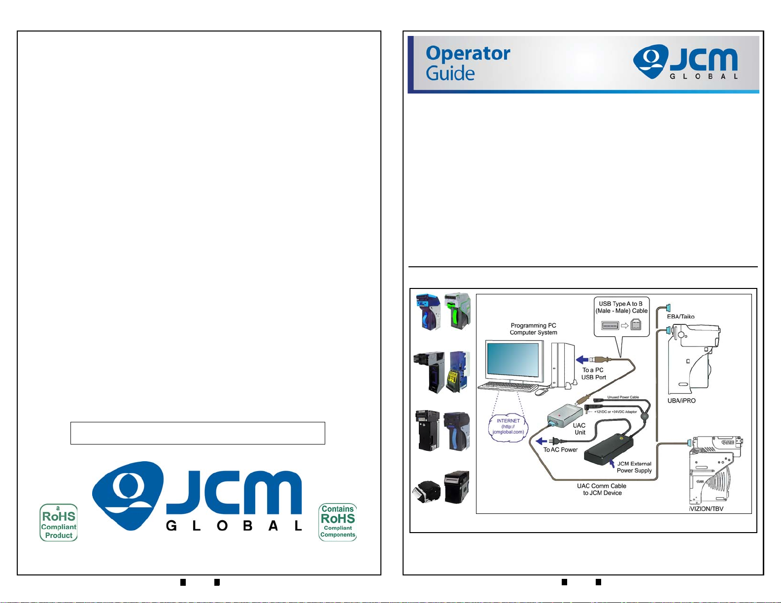
Figure 1 Primary UAC Kit Interconnection Scheme
Typical UBA & iVIZION
Units (Not Included)
Typical EBA & iPRO Units
(Not Included)
Typical TBV & DBV-30x
Units (Not Included)
Typical UAC Installa tion Equipment & Cable Requirements
Typical Taiko & Vega Units
(Not Included)
Operator Guide
JCM UAC™ Device
Operational Instructions
This document contains information for configuring and operating the JCM
Universal Acceptor Connector
™
The UAC
is a TTL and RS-232 to USB Protocol Converter that allows a JCM
Product to directly connect to a PC using its standard USB Communications
Port. JCM Products utilize either an Opto-isolated Current Loop (TTL) or an
RS-232 Protocol for communication.
™
The UAC
eliminates Jumper changing, Power Supply re-configuration, RS-232
Circuit Board removal, or using other complicated harness configurations to
connect a Banknote Acceptor to a Comp
UAC DEVICE KIT PRIMARY COMPONENTS
Figure 1 illustrates the primary component parts of a JCM UAC™ Kit.
™
(UAC) Device.
uter for testing operations.
Part No. 960-100194R_Rev. 3
© 2016 JCM American Corporation Part No. 960-100194R_Rev. 3 © 2016 JCM American Corporation
Page 2
2
7
JCM UAC™ Device Operator Guide September, 2016 JCM UAC™ Device Operator Guide September, 2016
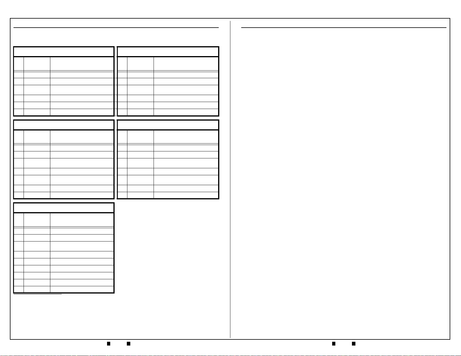
UAC™ INTERFACE KIT AVAILABILITY
Table 1 lists the five (5) available UAC™ Interface Kit components:
Table 1 Available UAC™ Interface Kits
UBA/iPRO UAC Kit (P/N 701-100103R) iVIZION/TBV UAC Kit (P/N 701-100112R)
JAC/JCMG
Qty.
Part
No.
1 501-100218R UAC Module 1 501-100218R UAC Module
1 G00286 DC Power Adaptor 1 G00286 DC Power Adaptor
1 302-100007RA
1 400-100249R USB Male A/B Cable 1 400-100249R USB Male A/B Cable
1 302-200409R UBA-WBA Comm Cable 1 40i-000026R Harness, iVIZION, UAC
1 960-100194R UAC Operators Guide 1 960-100194R UAC Operators Guide
Item & Part Number (P/N)
*
Power Adaptor AC Power Cord
(USA Version)
DBV-30x UAC Kit (P/N 701-000251R) Taiko (PUB7-11) UAC Kit (P/N 701-100104R)
JAC/JCMG
Qty.
Part
No.
1 501-100218R UAC Module 1 501-100218R
1 G00286 DC Power Adaptor 1 G00286
1 302-100007RA
1 400-100249R USB Male A/B Cable 1 400-100249R
1 G00599 Harness, DBV-30x Adapter 1 302-200410R
- 960-100194R UAC Operat ors Guide 1 3 02-200411R
- - N/A 1 960-100194R
Item & Part Number (P/N)
*
Power Adaptor AC Power Cord
(USA Version)
JAC/JCMG
Qty
.
Part No.
1 302-100007RA
JAC/JCMG
Qty
.
Part
No.
1 302-100007RA
Item & Part Number (P/N)
*
Power Adaptor AC Power Cord
(USA Version)
Item & Part Number (P/N)
*
UAC Module
DC Power Adaptor
Power Adaptor AC Power Cord (USA
Ver sion )
USB Male A/B Cable
Taiko PUB 7/11 ID-0E3 (ccTalk) Test
Adaptor Cable
Taiko ID-003 Test Adaptor Cable
UAC Operators Guide
PERSONAL NOTES AND COMMENT AREA
Write any pertinent notes or comments regarding your particular installation
here.
EBA UAC Kit (P/N 701-100105R)
JAC/JCMG
Qty.
Part
No.
1 501-100218R UAC Module
1 G00286 DC Power Adaptor
1 302-100007RA
1 400-100249R USB Male A/B Cable
1 302-200404R EBA-1x Test Adaptor Cable
1 302-200405R EBA-03 Test Adaptor Cable
1 302-200406R EB-200 Test Adaptor Cable
1 302-200407R EBA-3x/EBA-40 Test Adaptor Cable
1 960-100194R UAC Operators Guide
* JAC Product Numbers designate products developed by JCM American Corporation in the
USA and, JCMG EDP Product Numbers beginning with the letter “G” designate products
developed by JCM-E Germany.
Item & Part Number (P/N)
*
Power Adaptor AC Power Cord
(USA Version)
Part No. 960-100194R_Rev. 3 © 2016 JCM American Corporation Part No. 960-100194R_Rev. 3 © 2016 JCM American Corporation
Page 3

JCM UAC™ Device Operator Guide September, 2016 JCM UAC™ Device Operator Guide September, 2016
6
3
Figure 2 Primary UAC Kit Component Parts
UAC Module
Selectable DC Output Power Adaptor
USB
Male A
to B
Cable
NOTE: Component photographs are for illustration
only, JCM may change part manufacturer or
style, based on availability.
UAC Communications Cable
(Cable will vary by Acceptor)
Power Adaptor AC Power Cord
DB-9 Output End DB-9 Pin Configuration
Pins as viewed
from connector side
Power & USB Input End
USB-B Pin
Config
+DC
Input
Pin 1 = V Bus +5VDC
Pin 2 = DPin 3 = D+
Pin 4 = Ground
Pin 1 = LED Anode
Pin 2 = Tx (RS232/TTL)
Pin 3 = Rx (RS232/TTL)
Pin 4 = GND
Pin 5 = +12VDC or +24VDC
Pin 6 = LED Cathode
Pin 7 = Tx (SEB-40x)
Pin 8 = Reserved
Pin 9 = Reserved
PART NUMBER CROSS REFERENCE
Table 4 provides a cross reference comparison list of UAC™ Part Descriptions
related to various JCM Products th
Table 4 Part Number Cross Reference List
JCMG
Part No.
*
G00205 501-100218R
G00286
Use JAC #
Use JAC #
Use JAC #
→
→
→
G00262 40i-000026R
G00241 400-100669R
G00249
G00599
G00388
G00183 302-200411R
G00182 302-200410R
G00154 302-200409R
G00153 302-200404R
G00054 302-200405R
G00055 302-200406R
G00163 302-200407R
G00289
Use JAC #
→
GA0012
Use JAC #
* JCMG Product Numbers beginning with the letter “G” designate products developed by
JCM-E Germany.
† JAC Product Numbers designate products developed by JCM American Corporation in the
USA.
→
JAC
Part No.
†
← Use EDP #
302-100007RA
40i-000001R
302-000001R
← Use EDP #
← Use EDP #
← Use EDP #
← Use EDP #
400-000158R
← Use EDP #
960-100194R
at are supported with the UAC™.
Part Description
UAC Module
DC Power Adaptor
2 Prong, USA AC Power Cord
Harness Adapter, UBA to iVIZION
Harness, USB Cable Male A to mini B
Cable, Test Adapter, iVIZION/TBV
Cable, Test Adapter, Vega ID-003
Cable, Test Adapter, Vega ID-0E3
Cable, Test Adapter, DBV-30x
Cable, Test Adapter, iPRO-RC ID-003/cc-Talk
Cable, Test Adapter, Taiko ID-003
Cable, Test Adapter, Taiko ID-0E2 cc-Talk
Cable, Test Adapter, UBA/ WBA/iPRO
Cable, Test Adapter, EBA-1x
Cable, Test Adapter, EBA-03
Cable, Test Adapter, EB-200
Cable, Test Adapter, EBA-3x/EBA-40
Cable, Test Adapter, UBA-RC ID-003
Cable, Test Adapter, DBV-500
Cable, Test Adapter, DBV-400
Manual, UAC Operators Guide
UAC DEVICE KIT PRIMARY COMPONENTS
Figure 2 illustrates the primary component parts of a typical JCM UAC™ Kit.
UAC CONNECTORS
Table 2 illustrates and lists the connector types found on the UAC™ Device.
Table 2 UAC Connector Configurations
No. Connector Function Remark
+12 VDC 3.5A or +24 VDC 3.0A Input from
1
Power Adaptor
USB Type B Connector Jack
2
Serial 9 Pin-D Connector
Power Adaptor Input Voltage Range
= 110 to 240 VAC.
For USB Type A/B Cable connection
between the UAC and a PC USB
Jack.
For the Serial 9 Pin-D Connector of a
Part No. 960-100194R_Rev. 3 © 2016 JCM American Corporation Part No. 960-100194R_Rev. 3 © 2016 JCM American Corporation
3
Communications Cable to a
Banknote Acceptor’s Connector
(Cables can be ordered individually
for the Banknote Acceptor Model
desired).
Page 4

4
5
JCM UAC™ Device Operator Guide September, 2016 JCM UAC™ Device Operator Guide September, 2016
NOTE: The +12 VDC Power Adapter provides an operating Voltage designed to power
the Banknote Acceptor while running Diagnostic or Acceptance Tests.
NOTE: Ensure the proper Voltage level is set for the JCM Acceptor.
An incorrect Output Voltage can damage a JCM Acceptor.
Ensure the AC power source is disconnected from the Power Supply
before switching it’s DC Output Voltage levels!
Set 24 VDC Output
Set 12 VDC Output
NOTE: Ensure that the proper Voltage level is set for the JCM Acceptor being
tested. An incorrect Voltage setting can damage a JCM Acceptor.
ON
OFF
Four Position Piano Key
Snap Style DIP Switch Block
NOTE: All Switches shown
in the OFF Position.
SPECIFICATIONS
The UAC™ Specifications are as follows:
• USB 1.1 or USB 2.0 compliant
• Power consumption less than 100 mA
• Power Supply: Input = 110V to 240VAC, Output = + 12 VDC @ 3.5A & +24 VDC @ 3.0A
• Dimensions = 3.54 x 1.97 x 0.945 in. (90 x 50 x 24 mm).
UNIVERSAL POWER SUPPLY
P
OWER SUPPLY
I/O
• Input: 110V to 240VAC
• Output: +12VDC 3.5A or +24VDC 3.0A
One of the above two DC Voltage Levels is acceptable to most JCM Acceptors.
O
PERATIONAL VOLTAGE SELECTION
To switch Voltage levels, proceed as follows:
1. Disconnect AC power from Adapto r.
2. Use a Flat Blade Screwdriver to rotate the
Yellow Selector Switch to the desired
Voltage Output.
3. Reapply DC Adaptor’s AC power.
DRIVER INSTALLATION
A USB Driver needs to be installed so a PC will be able to communicate with
the UAC
UAC
™
. Perform the following steps to install the necessary Drivers for the
™
Device:
1. Download the required drivers from the following location, or contact JCM for
the required Device Drivers:
http://www.ftdichip.com/Drivers/VCP.htm
2. Select
the Virtual Comm Port (VCP) Drivers for the PC Operating System being
used on the PC. The CDM 2.04.16 (or newer) Application will be downloaded.
3. Run the CDM 2.04.16 Application to load the required Drivers onto the PC.
When the UAC
™
is connected, the PC will indicate that Drivers are needed.
4. Follow the prompts, selecting the Folder directory where the Drivers were stored
from the previous step.
Documentation for the UAC
™
Drivers is available at the following location:
http://www.ftdichip.com/support/ftdocuments.htm
LOCATING THE REQUIRED UAC COMMUNICATIONS PORT
Proceed as follows to locate the PC Comm Port being used by the UAC™:
1. Open the Control Panel on the PC.
2. Click the System ICON and select the Device Manager.
3. Open the required Ports (Comm and LPT).
4. Identify the Comm Port to which the UAC
™
is attached. This is the Comm Port
that will be selected by the application to enable the desired Banknote Acceptor
communications.
OPERATION
Proceed as follows to operate the UAC™ Device:
DIP SWITCH SETTINGS
The four position, Snap Style DIP Switch shown in Table 3 is used to set the
™
UAC
output signal levels.
Table 3 UAC Connector Configurations
1. Connect the UAC to the PC using the USB A/B Cable.
2. Connect the proper RS232C/TTL Cable from the UAC to
the Banknote Acceptor
(see list of Cables for JCM Acceptors in Table 4 on page 6).
UAC LED I
NDICATORS
The LED Indications present on the top of a UAC™ Device Housing are as
follows:
• The Green LED will light when the USB Communications Port is active,
indicating a good USB connection, and that power is applied to the UAC
• If either the USB connection is not established,
or power is not applied to the UAC™,
the Green LED will be OFF (Out).
SW No. Switch OFF Switch ON
• The Red LED
The Red LED indicates
the Status Indication for the Banknote Acceptor.
is
errors while in the Test or Diagnostic mode.
Refer to the appropriate Banknote Acceptor Service Manual for the proper
1
2
3
4
Part No. 960-100194R_Rev. 3 © 2016 JCM American Corporation Part No. 960-100194R_Rev. 3 © 2016 JCM American Corporation
TTL Output to Banknote Acceptor RS232C Output to Banknote Acceptor
RS232C for the SEB-40x Series BV Standard/Normal Setting
Reserved Reserved
Reserved Reserved
Code definition.
™
.
Error
 Loading...