

Page 1

Office: (800) 683-7248 Technical Support: (702) 651-3444 FAX: (702) 651-0214
E-Mail: techsupport@jcm-american.com Web-Site: www.jcm-american.com
Thermal Printer Series - 100
JCM part No. 960-000038
2002 JCM – American, Corp.
Page 2

Table of Contents
Introduction.............................................................................................................................. 1
Model Classification ................................................................................................................ 2
General Specifications ............................................................................................................. 3
Dip Switch Settings ................................................................................................................. 5
Thermal Paper Specifications .................................................................................................. 6
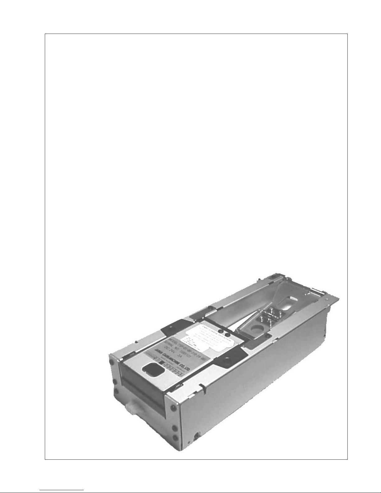
Photo of Printer ........................................................................................................................ 9
Pin Outs ................................................................................................................................. 10
Installation ............................................................................................................................. 11
Typical Mounting Holes ........................................................................................................ 11
Operation ............................................................................................................................... 12
Calibration ............................................................................................................................. 12
Troubleshooting ..................................................................................................................... 14
Cleaning ................................................................................................................................. 17
System Logic Diagram .......................................................................................................... 18
Illustrated Parts Breakdown ................................................................................................... 20
Parts List ................................................................................................................................ 21
JCM and the JCM logo are registered trademarks of Japan Cash Machine Co., Ltd. and JCM American Corpo-
ration. All other marks in this publication are registered trademarks of their respective owners.
Page 3
Introduction
The Thermal Security Printer – TSP-01
The TSP-01 is a multi-purpose printer that is
suitable for any application requiring quality
printing ability.
JCM provides the thermal paper specifications for optimum performance (see page X),
while allowing the customer the freedom to
create a unique 4-color design on the top
surface. The thermal side is reserved for the
barcode created by the thermal printer, which
is read by bill acceptors and other barcode
reading devices. The TSP-01 uses pre-cut,
pre-printed paper that offers the following
advantages:
• No curled paper or tickets from the end of
a roll that could cause a jam when inserted into a bill validator.
• No wasted paper such as found when
using roll or fanfold thermal paper.
• No complex paper loading procedures
such as found with rolled or fanfold
paper.
• Customers can reload the pre-cut paper at
any time to the maximum quantity.
Read-After-Write (RAW)
JCM’s RAW feature verifies the accuracy and
quality of the printed ticket prior to dispensing it. If the printer senses a problem, it
stores the ticket internally, and sends an error
message to the host machine. The printer
then attempts to reprint the ticket.
• No cutting device necessary within the
printer that can cause failures or malfunctions during operations.
1
Page 4

Model Classification
How to read the Model Classification Number
CATEGORY 813 TSP PRINTER
TSP – X X – X X – X XX – X X –XXX
(1) (2) (3) (4)(5)(6) (7) (8)
(1) TSP Thermal Security Printer
(2) CPU
01 4 MB EPROM w/barcode verify
(3) Mounting & Cable Bracket configuration
00 No mounting brackets, no cabling.
01 No mounting brackets, 024 cable output
02 Front hook bracket, long rear bracket; 024 cable output
03 Flat front bracket, short rear bracket; 024 cable output
04 No mounting brackets; ribbon cable output
05 No front bracket, small rear bracket; ribbon cable output
06 No front bracket; small rear bracket; ribbon cable w/header
(4) Paper capacity
3 250 notes
5 500 notes
(5) Paper size
1 65 mm x 156 mm (US $)
(6) Faceplate
0 No Faceplate
(7) Type of Software
03 ID-003 JCM Standard
24 ID-024 IGT Netplex
(8) Other Options
001 – Standard configuration
Examples:
TSP-01-05-310-03-001
Printer model 01 with no front bracket, small rear style mounting, 003 ribbon style cable; 250 note
capacity;
USA size paper; no faceplate; ID-003 software, no special options.
2
Page 5
General Specifications
Outside Dimensions
Width : 113 mm (4.448 inches)
Height : 67.5 mm (2.657 inches)
Depth : 279.4 mm (11 inches)
Weight
1.5 Kg, or 3.3 lbs
Power Requirements
DC 24V (+10%, -5%)
3A (50% print ratio)
Paper Hopper Capacity
250 standard.
Optional hopper extensions
for 500 pre-cut pieces available
Recommended Thermal Paper
Part No. KF50 - HDA or compatible
NOTE: Using other paper may affect the
quality and thermal printer head longevity.
Contact your JCM account repesentative
for a list of qualified suppliers.
Paper Dimensions
66 mm Width
156 mm Length
3
Page 6

General Specifications: Cont’d
Paper Rejection Function - .
R.A.W - Read After Write
When sensors detect double paper, or a barcode print failure condition, the paper is sent to an
internal reject area and an error code is sent to the host application.
The reject area has a capacity of 5 sheets.
Installation
Indoors
No Sunlight
A lengthwise installation angle between 0
Operating Environment
Temperature : +5O C ~ +45O C
Humidity : 10 ~ 90% RH (no condensation)
Storage Environment
Temperature : -25O C ~ +70O C
Humidity : 10 ~ 90% RH (no condensation)
O and 45O degrees
Types of Sensor Detectors
Paper Out Sensor
Paper Near Out Sensor
Paper Dispensed Sensor
Paper Reject Sensor
Double Paper Sensor
Barcode Read Sensor
Printing Method Dot Density Effective Print Dot Area
Thermal line dot method 8 dots / mm 480 dots wide
1200 dots long
Effective Print Area Maximum Print Speed Thermal Print Head Rating
60 mm X 150 mm 75 mm / second Pulse Life : 50 million pulses
Abrasion Life : 50 km
Handling Time
From receipt of data to full dispense : ~ 5 seconds
Paper pick up time (from box to head) : ~ 1 second
Print time : ~ 2 seconds
Dispense time (from print finish to full dispense) : ~ 2 seconds
4
Page 7
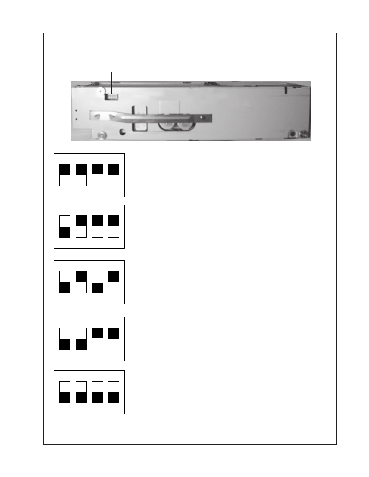
Dip Switch Settings
Dip Switches
OFF
4 3 2 1
OFF
4 3 2 1
OFF
4 3 2 1
OFF
4 3 2 1
Normal Operating Setting - This is the default setting for
normal communication via the host application.
Dip Switch #1: Off = Barcode check
On = No barcode check
Others are default to OFF position
Coupon Print Test - Will print a ticket and check the barcode. If
there is something wrong with the barcode, VOID will be printed
on the ticket and it will be transported to the reject area.
Print Bar Sensor Signal and Data - A barcode ticket is printed.
The sensor signal and data are printed on the following piece of
paper. This is used to make sure barcode and transparency sensors are adjusted properly.
Print Test pattern and Version Information - Print a test
pattern, model name and version number. This feature is useful
for quickly checking print quality.
OFF
4 3 2 1
NOTE: Dip switches must be set with the power OFF. W#hen power is turned ON, the operation begins.
Adjust Barcode and Transparency Sensors - To be used when
attempting to use the Sensor Adjustment procedure.
5
Page 8

Thermal Paper Specifications
1. Overview
This specification is for thermally coated tickets designed for use with the JCM
TSP-01 thermal printer.
2. General Characteristics
2.1 Tickets to be pre-cut sheets.
2.2 Ticket edges must be smooth to prevent double feeding.
2.3 Ticket size: 65 ± 1 mm x 156 ± 1 mm.
2.4 Tickets to be supplied in bulk stacks of 200.
2.5 Each stack shall have a tear off band.
2.6 Tickets must be processed and cut in a manner that minimizes paper dust.
3. Thermal Paper Specification
ITEM SPEC.
Weight g/m² 102 Avg
Caliper µ 114 Avg (4.5 mils)
Brightness % 89 Avg
Smoothness sec. 2000 Avg
Image Colors Black
Initial Activation Temp. ° C 74 ± 5 O.D. = 0.2
Effective Activation Temp. ° C 83 ± 5 O.D. = 0.8
Optimum Activation Temp. ° C 90 ± 5 O.D. = 1.2
Resistance of Oils Very Good
Resistance of Alcohol, Solvents Very Good
15 Hr. Water Immersion Very Good
6
Page 9

4. Paper Curl
The deformation (curl and warp) of papers used for TSP-01 printers is limited as follows.
Deformation to be measured after paper has been stabilized for a minimum of 48 hours
at 20 ± 5o C, 55 ± 15% RH.
POSITIVE WARP
ZERO ALLOWED
POSITIVE CURL
ZERO ALLOWED
THERMAL SIDE UP
NEGATIVE CURL
5MM TOTAL MAX.
5MM PER 67MM IS
.075INCHES/INCH
THERMAL SIDE UP
NEGATIVE WARP
5MM TOTAL MAX.
5MM PER 156MM IS
.032INCHES/INCH
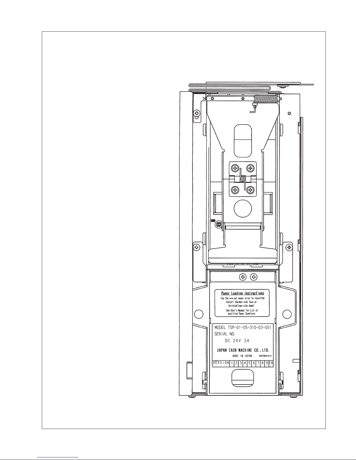
5. Thermal side printing
5.1 Ticket shall have the text: “INSERT THIS SIDE UP” preprinted in heat resistant
black ink along the 65 mm edge as show in Figure 1. Font size shall be 12 pt.
5.2 Lot code, date code or other information identifying the printing date or batch number
shall be printed in heat resistant black ink along one of the 65 mm edges as shown in
Figure 1. An arrow or other symbol indicating paper grain orientation shall also be
included. Font size shall be 4 pt.
5.3 No other preprinting is allowed on the thermal side without prior approval of JCM
American Corp.
6. Non-thermal side printing
6.1 The non-thermal side may be preprinted with multi colored graphic images. All
printing on the non-thermal side must be within the area shown in Figure 2.
7
Page 10

6.2 It is recommended that non-thermal side printing be pre-approved by JCM American
Corp. prior to use to ensure no negative impacts on print or printer reliability.
7. Packaging
7.1 Paper shall be packaged in cartons or boxes designed to protect tickets from damage.
7.2 Packaging must shield tickets from ambient light.
7.3 Package to have “THIS SIDE UP” or similar marking in large bold print to ensure
that tickets are shipped and stored horizontally to minimize warp and curl.
7.4 Package to have suggested storage temperature and humidity conditions printed on
carton. (Example: Store at 70oF and 50% RH)
8
Page 11

Paper Positioning Guide
Positioning
Sensor and
Doubler Paper
Sensor
Positioning
Sensor
and Double
Page Sensor
Barcode
Sensor
Positioning
Sensor
Exit Sensor
Positioning Sensor & Double Page Sensor
9
Page 12

Pin Outs (ID-003)
FUNCTION SIGNAL PIN
N/C 1
N/C 2
Green edge of ribbon
N/C 3
N/C 4
N/C 5
RS-232CTXD TXD 6
RS-232CRXD RXD 7
LED POWER (24V) RCTR24 8
N/C 9
LED GND COM 10
N/C 11
N/C 12
RS-232 GND GND 13
N/C 14
N/C 15
N/C 16
DC24VDC 24V 17
DC24VDC 24V 18
GND PGND 19
GND PGND 20
* N/C = Not Connected
10
Page 13

Installation
1. Install the printer mounting frame in the host
machine using the appropriate mounting holes in
the bottom of the frame.
2. Attach the ribbon cable to
the host machine.
3. Slide the printer into the
frame by pushing in on the
arm covering the EPROM.
Attach the ribbon cable to
the printer before pushing
the printer all the way in.
Typical Mounting Hole Locations
11
Page 14

Operation
Loading the Paper
1. Fan the pre-cut paper before placing it in
the hopper.
2. Lift the spring-loaded pressure plate.
3. Place the paper stack in the hopper with
the printed side down.
4. Release the pressure plate.
NOTE: The hopper will hold 200 sheets of
pre-cut paper unless the hopper extension has
been added.
5. Replace the printer in the host machine.
Calibration Procedure
1. Make sure the power is turned off or disconnected
from the printer.
2. Put all Dip switches in the ON position (see Fig. 1).
3 Open the printer head by pulling the printer halfway out of
the frame and pulling up on the metal bar.
4. Place the white calibration paper (Part No. 501-000045)
over the barcode and double-note sensors (see Fig. 2).
5. Close the printer head.
6. Apply power to the printer (30 second warm-up delay).
7. The LED flashes, 100 ms ON, 1 sec. OFF (see Fig. 3).
8. Open the printer head and remove the white calibration
paper.
OFF
4 3 2 1
Figure 1.
12
Figure 2.
Page 15

LED
Figure 3.
9. Place the black calibration paper (Part No. 501-000044) in the same position.
10. Close the printer head.
11. Move Dip switch No. 4 to OFF (see Fig. 4)
12. The LED flashes 100 ms ON, 1 sec. OFF (see Fig. 3).
13.Open printer head and remove the black calibration paper.
14.Place the white calibration paper over the barcode and
double-note sensors again.
15.Close the printer head.
16.Move Dip switch No. 1 to OFF (see Fig. 5).
17.Wait until the LED comes on steady, approximately 15
seconds (A blinking LED indicates an error).
18.Open the printer head and remove the white calibration
paper, then close the head.
OFF
4 3 2 1
Figure 4
OFF
4 3 2 1
Figure 5
OFF
4 3 2 1
19.Move Dip switch No. 3 to OFF (see Fig. 6).
20.The LED flashes, 200 ms ON, 200 ms OFF.
21.Turn off the power to the printer.
22.Move all Dip switches to OFF.
Figure 6
13
Page 16

Troubleshooting
When the printer receives a message from the host, it moves a single piece of paper from the
hopper into the printer and prints the barcode information. The piece of paper is moved into
another section where it is read to confirm accuracy. If there is an error condition, it moves
the paper to the reject area, informs the host there was a problem, and waits further
instructions.
If the printer detects more than a single piece of paper, it moves the paper to the reject area
and attempts to re-print the ticket.
When the printer prints a single piece of paper and reads accurate barcode information, it
releases the paper.
Out of paper sensor
There are two sensors in the hopper section.
One sensor informs the host that the supply of
paper is low, and the other sensor informs the
host when the hopper is empty. There are
other sensors along the path the paper takes
that detect double papers and positioning.
Paper low sensor
If there is a paper jam, the printer sends a
message to the host and the host signals a
paper jam. The only time a service technician
becomes involves with the printer is when
there is a paper jam, where there is a software
update, and when the printer needs more paper (see “Loading Paper”).
Whenever the printer requires service, it is recommended that the reject area be cleared. To
do this disconnect the ribbon cable from the computer, remove the printer from the frame,
turn it over and remove the tickets.
14
Reject area
Page 17

Troubleshooting (Cont.)
It may become necessary to increase the
printer contrast if the host receives a
contrast error message. Use a small flathead screwdriver to adjust the contrast
control wheel (lower numbers increase
contrast). Make minor adjustments, then
test the printer to verify the results.
To replace the EPROM, it is necessary to
remove the four (4) screws securing the
side of the printer. Do not remove the
screw securing the spring-loaded bar.
Slide the side panel toward the rear of the printer to release it.
When replacing the side panel, make sure all the tabs are inside the body slots before sliding
the panel toward the front of the printer. Secure it with the four (4) screws.
15
Page 18

Troubleshooting (Cont.)
Problem Possible Cause Possible Solution
No power
Printer reject
Printer reject
1. Ribbon cable not seated
properly
2. Printer is not all the way
in the frame
Double paper sensed
a. Sheets automatically go
to reject area
b. Printer will try to print a
single sheet for 20 seconds
c. Printer will send failure
message to host
Bar code error
a. Mismatched bar code
data
b. Incorrect narrow bar
width
c. Incorrect wide bar width
d. Black/white contrast too
low
e. Too many bars
f. First bar code character
invalid
Check ribbon connector at the rear
of the printer
Make sure the printer is all the way
in the frame
Remove all paper from the paper
hopper and fan it
Load additional sheets in paper
hopper
Run test to make sure paper pickup isn’t worn.
Clean the printer, test the software
Clean the printer, test the software
Clean the printer, test the software
Adjust with contrast screw
Clean the printer, test the software
Clean the printer, test the software
Paper jam in
hopper
Paper jam in
printer
Printer will not
accept Print
message from
host
16
Mis-aligned paper
Mis-aligned paper
Printer head overheated
Remove all paper from the paper
hopper and fan it.
Remove jammed piece.
Carefully replace paper in hopper
Open printer head.
Remove jammed piece.
Test for proper alignment
Once the print head has cooled
down, this problem will not occur.
Page 19

To clean the TSP-01 remove all
paper from the hopper and use
compressed air to blow out any
residue. Concentrate on the
rollers and the sensors.
Cleaning
Open the head and use compressed air to remove any
debris from the area. Then use
a lint-free cloth and a 25%
alcohol solution to gently
clean the head area indicated
in the photograph.
17
Page 20

18
System Logic Diagram
Page 21

System Logic Diagram (Cont.)
19
Page 22

Illustrated Parts Breakdown
20
Page 23

PARTS LIST
No. EDP Part No. Description Qty.
1 071874 0667PT0110B Side Cover (R) 1
2 071875 0667PT0111B Side Cover (L) 1
3 071846 0667BU0101A Slide Guide Bush 3
4
5 025205 M3X5 Bind (Fe CR) 9
6 071872 0667PT0108B Harness Guide (L) 1
7
8 074078 0667KS0106 Paper pusher spring 1
9 073770 0667PT0125A Paper pusher (B2) 1
10 072277 0667PT0120C Paper pusher (A) 1
11 073769 0667PT0124A Paper pusher (B1) 1
12 073773 0667SH0117A Paper pusher F 1
13 073775 TH-61SUS-1 Spring Hinge 1
14 073774 0667SH0118B Paper pusher shaft 1
15 071873 0667PT0109A Front plate 1
16
17 071901 0667PE0104B Sub Board Seat 1
18 071882 667-3140-06-02C-01 I/F Assy 1
19
20
21
22
23 071849 667-3140-06-06A-01 Barcode sensor PCB 1
24 040342 RE-7AJ04A Sensor bush (f 5) 2
25 052523 0943RE0129A Bush (RE) 1
26
27 071867 0667PT0102B Head bracket 1
28 071842 0667SH0113 Head shaft 1
29 071885 0667CS0102 Head spring 2
30
31 071909 0667RE0101 Pinch roller 7
21
Page 24

No. EDP Part No. Description Qty.
32
33 071884 0667CS0101 Tension roller spring 2
34 071913 0667RE0105 Spring stopper 1
35 071921 0667RE0113B Upper guide 1
36 071920 0667RE0112 Reject lever 2
37
38 071836 0667SH0107 Lock shaft 2
39 071881 0667TS0102 Lever spring 2
40 071880 0667TS0101 Lock spring 1
41
42
43 071761 3140-05-04A Sensor (B) harness 1
44 071900 0667PE0103B CPU Board seat 1
45 071768 667-3140-06-0 1B-01CPU Assy 1
46 071760 3140-05-03D Sensor harness 1
47 071914 0667RE0106 Gate roller cover 1
48 071843 0667SH0114 Gate roller shaft 1
49 071886 0667CS0103 Gate roller spring 2
51 071856 0667RU0104 Gate roller 1
52 017669 NHF06 One way clutch 1
53 071907 0667GE0105A Feed gear 4
54 071922 0667RE0114 Clutch 1
55 071847 0667CO0101 Clutch collar 1
56 071887 0667CS0104A Clutch spring 1
57 033218 DDLF-850ZZ Bearing 8
58 072272 5X7XT0.4 Polyslider 6
60 071906 0667GE0104A Feed gear (B) 4
66 071915 0667RE0107A Gate roller guide 1
67 071839 0667SH0110 Feed shaft 1
69 071853 0667RU0101 Platen 1
76 071908 0667GE0107A Idol gear (C) 5
78 034397 B-F5-53 Metal bearing 6
82 071904 0667GE0103A Feed gear (A) 1
22
Page 25

No. EDP Part No. Description Qty.
83 071903 0667GE0102 Idol gear (A) 1
84 071905 0667GE0106 Idol gear (B) 1
102 071918 0667RE0110A Lower guide (C) 1
103 071863 0667SH0104 Pinch roller lever F 1
104 071890 0667KS0103 Pinch roller SP(B)R 1
105 071891 0667KS0104 Pinch roller SP(B)L 1
106 071848 667-3140-06-04A Refractive sensor 4
107 052524 0943RE0130A Bush (LED) 3
109 071869 0667PT0104 Pinch roller lever 1
111 071864 0667SH0105 Pinch roller shaft (C) 1
112 071865 0667SH0106 Pinch roller shaft (D) 1
114 071895 0667AS0103B Side frame (L) assy 1
120 071916 0667RE0108A Lower guide (A) 1
123 071917 0667RE0109A Lower guide (B) 1
129 071919 0667RE0111 Lower guide (E) 1
130 071859 0667SH0101 Pinch roller BKT F 1
131 071888 0667KS0101 Pinch roller SP(A)R 1
132 071889 0667KS0102 Pinch roller SP(A)L 1
137 073918 PM35L048ZWE5G Stepping motor 1
139 071876 0667PT0112 Unit base 1
140 046767 M3X8 Pan screw 2
141 077339 0667PT0135 Paper pusher plate 1
142 077341 0667PT0136 Upper guide plate (L) 1
143 077340 0667PT0134 Upper guide plate (R) 1
144 M3X5 Bind (Black) F 3
145 076149 0667SH0119 Feed shaft (G) 1
146 071912 0667RE0105A Feed roller (C) pulley 6
147 071857 0667RU0105A Feed roller (C) 6
148 075615 667-3140-05-50-01 Buzzer assy 1
149 078241 0667PR0902 PCB SIM plate (4)
23
Page 26

Office: (800) 683-7248, Tech. Support: (702) 651-3444, FAX: (702) 651-0214
E-mail: techsupport@jcm-american.com http://www.jcm-american.com
925 Pilot Road, Las Vegas, Nevada 89119
 Loading...