

Page 1
1
Triton
INSTRUCTION MANUAL
Page 2

2
CONTENTS
Introduction ......................................................................................................................... 3
Where to find the Serial No & Size Labels .......................................................................... 3
Measurements & Useful Info ............................................................................................... 4
Seating System Components ............................................................................................. 5
Important Safety Advice ...................................................................................................... 6
Important Safety Advice -(Accessories) .............................................................................. 7
Operating Brakes (Indoor Base Frames) ............................................................................ 7
Important - Chest Harness Adjustment .............................................................................. 8
Important - Lap Strap Safety ............................................................................................... 9
Useful Info - Adjustment Points & Lever Use .................................................................... 10
Lever Use - Using Index Plungers ..................................................................................... 11
Adjusting Shoulder Protraction Pads ................................................................................ 11
Mounting of Seating Unit................................................................................................... 12
Removal of Seating Unit .................................................................................................... 13
Manual Seat Height Adjustment (Multi Height & Tilt Base) .............................................. 13
Powered Base Height Adjustment (upgrade option) ........................................................ 13
Tilt In Space (Multi Height & Tilt Base) .............................................................................. 14
Folding Push Handle (Multi Height & Tilt Base) ................................................................ 14
5 Star Base Adjustments ................................................................................................... 15
Back Angle Adjustment ................................................................................................... 16
Back Height Adjustment ................................................................................................... 16
Seat Depth Adjustment ..................................................................................................... 17
Fitting a Tray ...................................................................................................................... 18
Sacral Pad Adjustment ..................................................................................................... 18
Hip Pad Adjustment .......................................................................................................... 19
Thigh Pad Adjustment ....................................................................................................... 20
Headrest Adjustment ........................................................................................................ 22
Lateral Support Adjustment ............................................................................................. 23
Arm Rest Adjustment ........................................................................................................ 24
Legrest Adjustment & Removal– Split Option................................................................... 25
Foot Positioning Adjustment ............................................................................................. 26
Setting Up the Dynamic Back Mechanism ....................................................................... 28
Cleaning & Care ................................................................................................................ 30
General Maintenance ........................................................................................................ 30
Servicing via Approved Repairer ....................................................................................... 31
Service Record Log ........................................................................................................... 32
Warranty ............................................................................................................................ 33
Inspecting & Reissuing of Equipment ............................................................................... 34
Page 3
3
The Triton is designed to provide comfort and postural support. The system is available in
five sizes to accommodate children from as young as 6 months through to adult.
This instruction manual contains very important information about the Triton seating
system, how to use it safely and obtain the best results from it. Please read all the
information contained in this manual before using the chair and retain for future
reference. Ensure everyone using the equipment is aware of the contents of this manual
and understands how to use the equipment safely.
These instructions provide guidance on the adjustments for professionals, but they also
give information on how the equipment should be safely used, maintained, checked, and
correctly assembled by anyone who uses the seating system.
In every case the equipment should be supplied via qualified professionals who will have
adjusted the equipment, checked its compliance and tested it appropriately.
The seating system should only ever be adjusted by qualified professionals and persons
that are suitably trained. For further information please do not hesitate to contact us - all
contact details are on the back cover of the manual.
Thank you for purchasing our product, we
hope you enjoy your new seating system.
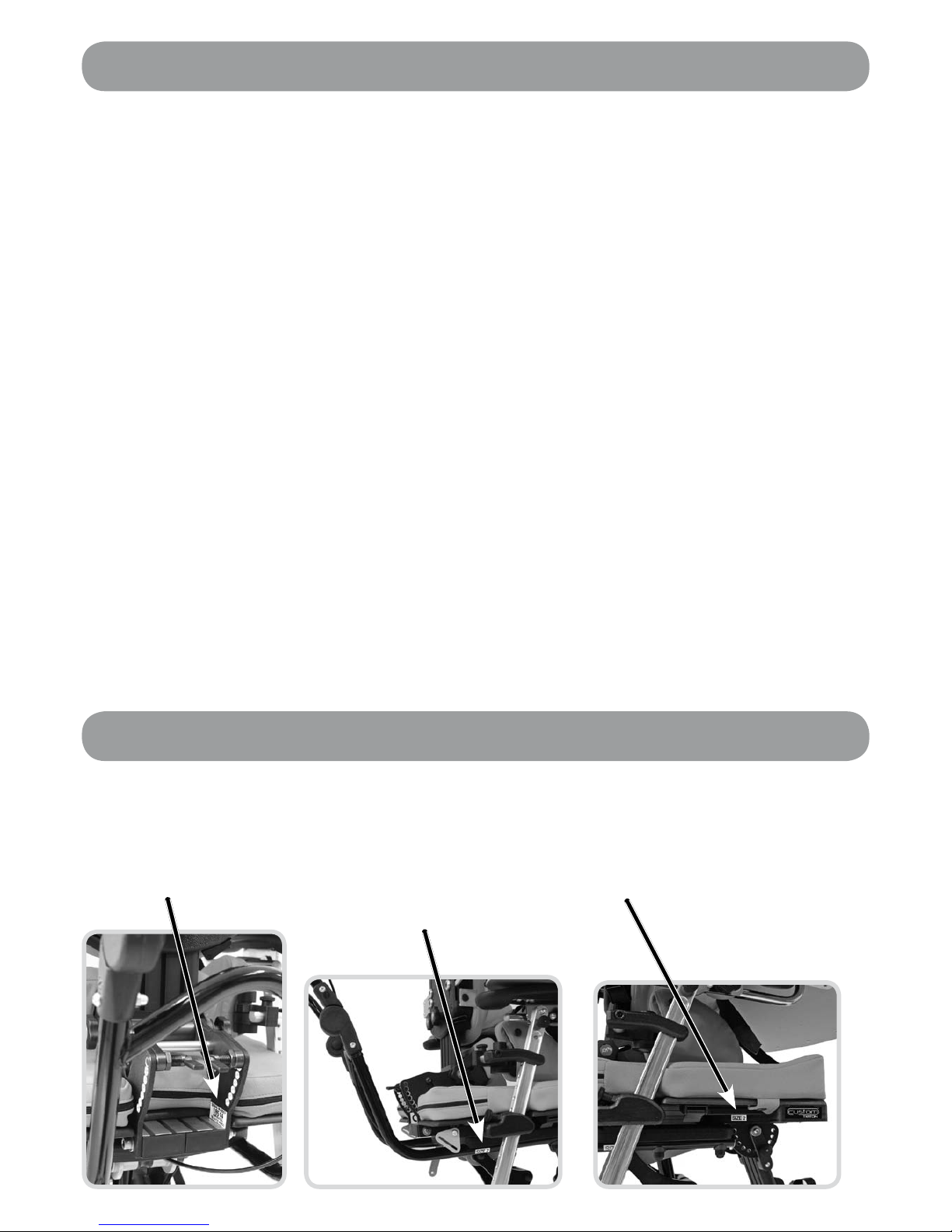
Where to find the Serial No & Size Labels
Handle Size
Located on the
right hand side
of the handle
where the handle
feeds beneath the
seating unit.
Serial Number
Located at the lower
back of the seat on
the inside of the back
angle adjustment
section.
Introduction
Seating Unit Size
Located on the right
hand side underneath
the seating unit, just
above where the leg
rest joins.
Page 4

4
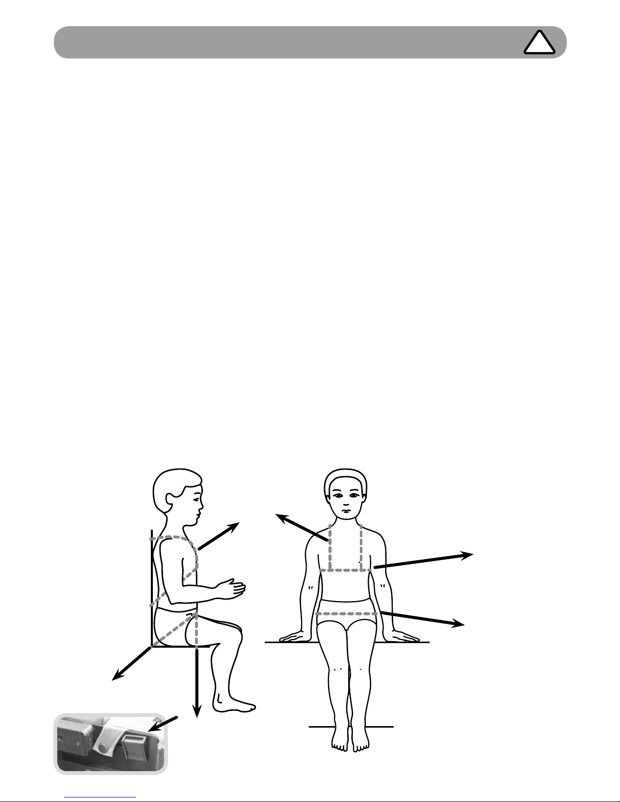
Measurements & Useful Info
MEASUREMENTS (mm)
Triton 0 Triton 1 Triton 2 Triton 3
Notes
MIN MAX MIN MAX MIN MAX MIN MAX
A Seat Depth 150 300 200 350 300 450 400 550
B Seat Width
(Between Hips)
125
225
(290)
150
250
(315)
230
330
(395)
310
410
(475)
(mm) - When Hip
Pads Removed
C Seat to Top of Shoulder 260 360 300 440 390 560 480 680
D Chest Breadth 125 225 150 270 230 350 310 430
E Seat to Footplate 120 300 190 370 260 440 330 510
Leg Length has 2 Settings
to Achieve Min/Max
F Seat to Back Angle 25° Recline 5° Forward
Seat Weight 13.5 kgs 14.5 kgs 17.0 kgs 19.5 kgs
Guideline (inc Arms, Hips,
Lats, Footplates)
Load capacity 100 kgs
Always Refer to Chassis
Capacities
Age Guideline
3 months - 3
years
4-9 years 8-13 years 12-adult
Measurements when fitted to Multi Height & Tilt Base
G Seat to Floor
75mm Castor: Min - 325
/ Max - 785
100mm Castor: Min - 355
/ Max - 815
100mm is Standard
H Tilt / Prone Angle 25° Tilt / 15° Prone
I Base Footprint 740 x 570mm
The Triton is a modular seating system where at assessment the selection of Seat, Back and Leg Widths & Lengths can be
specified. The Seating system will then be built to ensure best fit & maximum growth from the outset. Dimensions provided
here provide guidance on the standard sizes available.
Please note that all measurements given are for indication only. JCM can tailor the chair to your precise
requirements. Our Product Specialists will assess your child to ensure the chair is fit for purpose both
now and for the future.
F
E
A
H
G
C
B
I I
D
Page 5
5
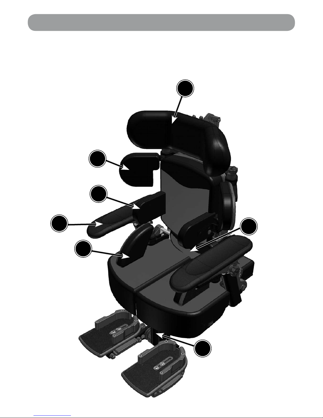
Seating System Components
A
C
D
E
B
A Headrest
B Shoulder Protraction Pads
C Lateral Supports
D Hip Pads
E Sacral Pad
F Armrest
G Legrest
G
F
Page 6

6
• Ensure all adjustment mechanisms are secure and in place before operation. If it is
likely that the hand-wheels will be repeatedly loosened, JCM can supply allen key
bolts as an alternative. We strongly recommend this if there is a danger from those in
the vicinity of the user.
• After completing any alterations ENSURE all nuts, bolts, knobs, hand wheels and
other fixings are securely tightened and in position, and that they are regularly
checked as part of the maintenance of the chair. Never over adjust or over tighten
moving parts.
• All postural support straps and harnesses should be in place and properly adjusted to
the user, prior to usage of any kind (see pages 8 & 9).
• When fitted to an indoor base frame the Triton should always be positioned on a
level, flat floor. The Triton chair can be moved between one working area and another.
For safety ALWAYS return the product to a neutral position and lower before moving
(lower in height, level the seat, ensure the back is upright etc). After the chair has been
moved and during use the chair should be placed in a static position with the brakes
applied. Indoor base frames such as the multi height and tilt base are designed to be
used inside, however it is acceptable to take these bases externally for a brief period if
transferring the chair from one indoor area to another.
• Heavy items on the tray will affect stability. The fitting of anything other than the
standard JCM tray may substantially affect the stability of the seating system and
should therefore be checked before issue.
• If at any time it is noted that areas of the users skin remain reddened after being out of
the seating system for around 10 minutes, urgently contact the qualified professional
who performed the hand over of the equipment. This may be a sign of excessive
pressure being exerted by the seating. This might occur in the initial use of a new seat
where further adjustment may be required, where the user has been badly placed,
grown or where an underlying medical problem exists. Review may be necessary in
such cases
• Keep all products away from excessive sources of heat, cigarettes and naked flames.
• If you suspect that the system may be faulty, cease use of the equipment straight
away and immediately contact the organization who supplied the system. (JCMs
contact information can be found on the back cover).
• The equipment will be labelled with important information. NEVER REMOVE these
information labels or allow them to be defaced, overlaid or altered.
• All modifications, adjustments, reconditioning, repairs, disposal, and servicing of the
seating unit must ONLY be carried out by the agencies who supplied the equipment
(see pages 30-31).
Important Safety Advice
!
We at JCM are committed to producing products of the highest standard. All of
our products fulfil the essential safety and environmental requirements as defined
in the European Directives. However, improper use of the products will potentially
put the users at risk and therefore JCM strongly suggest that the following
information is strictly adhered to at all times.
Throughout the manual there are important points to note identified by the symbol:
!
Page 7
7
Important Safety Advice -(Accessories)
!
Multi Adjustable Head support
Wings on the head support are ideally set at 45 degrees. Do NOT bring the wings in tight
to the head. Ensure that the head support is set in such a way that the child cannot loop
their head around the wings and get stuck.
Flexi-Supports and Lateral Supports
Ensure the straps do not infringe on any feeding tubes the child may have.
Abductors
These parts are designed to abduct the users knees to help keep the hips in a good
position. Do NOT use the abducters as a way of holding the user in the seat. Flip down
the abducter when transferring the user in and out of the seat.
Foot Sandals and Straps
Should only be fixed when the user is wearing shoes or boots.
Tray
Do NOT use the tray as a way of securing children in a chair always ensure that the lap
strap and any other straps supplied are used. Ensure that the tray clips are secure on
both sides of the tray. If the tray is damaged, ensure that this will not be a hazard to the
user. Never leave hot items on the tray while children are unattended.
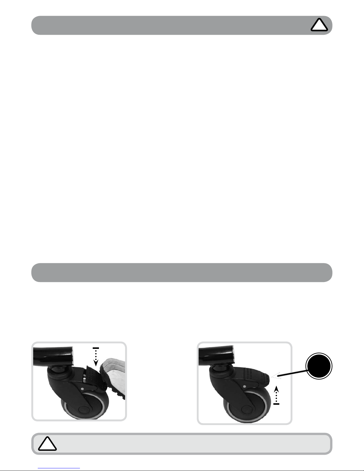
Operating Brakes (Indoor Base Frames)
Always apply the brakes while the chair is stationary.
!
Applying Brakes
Depress lever (A) with your foot. To
secure the chair in place you should
suppress all the brakes fitted to the
wheels on the base.
Releasing Brakes
To release the brakes you should flick
the levers up using the top of your foot.
When all brakes are released the chair
will be free to travel in any direction.
A
Page 8
8
If there is any possible chance of the child getting the straps caught around
their neck, REMOVE THE HARNESS IMMEDIATELY.
!
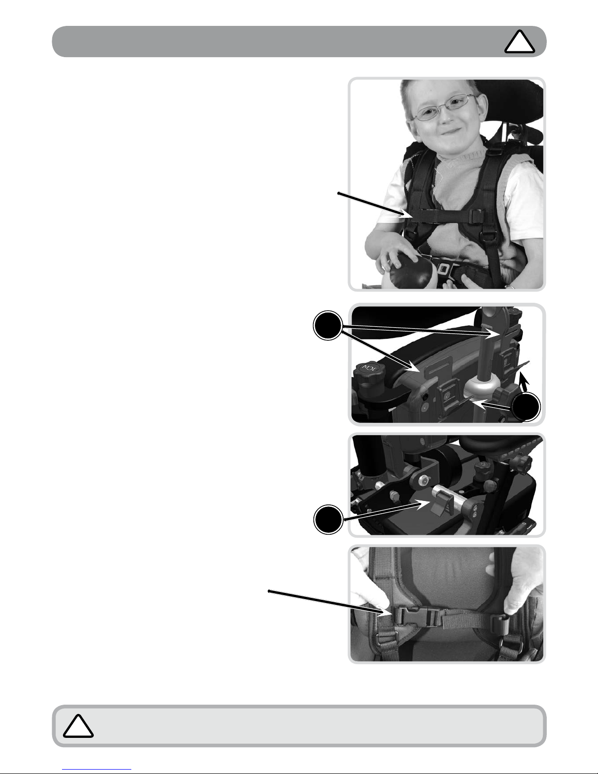
Important - Chest Harness Adjustment
GREAT CARE should be taken when fitting a
chest harness and the following points should
always be followed:
• The straps on the harness should never be
allowed to move close to or in any way cause
an obstruction to the childs neck.
• The straps should never be fitted too tightly and
should be clear from any obstruction.
• The sternum strap on the chest harness should
always be adjusted prior to use to ensure that it
is no higher than the middle of the users chest.
• A lap strap should always be fitted if a harness
is being used to ensure the child cannot slide
down onto the sternum strap.
• Always ensure that the belts offer your child
both comfort and support. If the childs clothing
has been adjusted (i.e. a jumper removed) the
straps should be re-adjusted accordingly.
Fixing Onto Chair
• The Triton comes with guide plates for the
top straps which are located either side
of the upper back (A). The webbing strap
should be fed through these guides and then
adjusted and secured in place using the cam
buckle clasps (B) directly beneath the guide
plates.
• The straps at the bottom of the harness
should be fed through, adjusted for fit and
then locked using the Cam Buckle Clasp (C)
located on the hip pad rail.
Fastening of Belts
• Feed the fabric belt through
the buckle on the strap.
• The belts should be pulled through
enough to suitably support your
child whilst still being comfortable.
• When this has been achieved the
buckle should be snapped closed
to secure the strap in place.
!
The same precautions highlighted here should be adhered to when using any form of
trunk supports or flexi supports with straps.
A
B
C
Page 9
9
Important - Lap Strap Safety
Lap Strap Fitting
The angle that the hip belt is attached to the seating
system has a direct effect on the angle of pull on the
pelvis.
Considerations:
• A 60° angle of attachment to the seat rail positions
the hip belt anterior and inferior to the ASIS, which
reduces the tendency of the client with a posterior
pelvic tilt to slip underneath the belt.
• A higher angle of attachment of the primary straps
encourages a posterior pelvic tilt, which assists in
positioning clients with an anterior pelvic tilt.
• The secondary straps of a 4-point hip belt are
attached to the seat post between 45° and 90°
to hold the primary padded strap in place and to
prevent the belt from riding into the abdomen or
twisting.
• The angle of attachment may have to be
compromised in order to accommodate such
situations as wounds in the pelvic area, unstable
hip joints or gastric tubes.
Tightening the belt
Keep belt tightened at adjustment straps during fitting
and daily use to ensure correct pad placement. For
padded hip belts the pads are to be touching when
correctly tightened. For non-padded hip belts the
adjustment strap at the buckle should be approximately
3” (76mm) long. Education of the care giver is essential
for correct hip belt positioning.
Sizing
Measure hip width to determine the belt size required.
The suggested method for measuring hip width is from
trochanter to trochanter. If this is not possible, measure
from ASIS to ASIS and add a couple of inches. The
correct belt size for the individual has padding that
covers all of the bony prominences.
• Always check that the child’s pelvis is symmetrical
and positioned securely at the back of the seat.
• Always ensure that the lap straps and chest
harness hold the child securely and are
comfortable. Ensure they provide a snug fit, a
simple rule of thumb is to allow two fingers to be
inserted between the belt and the childs body.
• Never leave a child in a chair unattended without
the lap strap being fastened.
• A lap strap should always be fitted if a harness is
being used.
• When altering the angle between the seat and
the back of the chair always re-adjust the chest
harness and lap strap accordingly to ensure all
safety recommendations are followed.
!
Chest
Harness
Fitting
The cross strap on
the chest harness
must be fitted no
higher than the
sternum (mid
chest).
All straps &
harnesses must
be securely
fitted to the
back of the
chair.
Incorrect fitting of lap straps can put the user at serious risk. When using lap straps we recommend
the following points should always be adhered to:
Harness and Lap Strap Positioning
This diagram shows the recommended positioning of the chest harness and lap straps:
Primary Lap
Strap Fitting
Primary Lap Strap
Fitting
Secondary lap
strap fitting (fourpoint lap strap)
Page 10
10
Useful Info - Adjustment Points & Lever Use
Lap belt front
fixing buckle
Seat depth
adjustment
bolts
Footplate
width
adjustment
Adjustments Points Underneath Seat
Effective Operation of Lock Levers (Where Fitted)
A
B
Never remove these levers entirely as this
will prevent you from being able to perform
adjustments in the future.
• To use: Turn the lever handle clockwise
to tighten or anti clockwise to loosen.
• To use the lever when an obstruction
is met: Pull the handle of the lever
outwards, towards you (A). This disables
the function of the lever.
• Continue to hold the lever out and
reposition the lever handle in a suitable
position past the obstruction.
• Release the handle to re-engage the
lever function (B) and continue to tighten
or loosen in the normal way.
• Repeat this procedure in areas where
adjustment is restricted due to an
obstruction.
Footplate
Angle
Adjustment
Page 11
11
Using the Index Plungers (Locking Variety Only)
• To place the plungers in an open position - Pull out the plungers to maximum tension and
turn them through a half turn anti-clockwise (B). This places them in an open position (C).
LOCKED
TURN
OPEN
A
C
B
• To close - Turn the plungers a half turn clockwise and they should snap back into a
locked position (A).
Lever Use - Using Index Plungers
Adjusting Shoulder Protraction Pads
Pad/ Shoulder Width
• Turn locking screw (A) half a turn using
the 4mm Allen Key provided, manually
position the pad to fit the user by sliding
the pad in or out.
• Lock the pad in place by re-securing
locking screw A.
Pad/Protraction Angle
• To set the angle of the pad you should
loosen the securing handwheel (B) by
rotating a couple of turns in an anticlockwise motion. Once released the
pads can be positioned by pressing
down on the handwheel whilst
simultaneously altering the angle of the
pad using your other hand.
• Once the desired position has been
achieved you should release the
handwheel and resecure it by turning in
a clockwise direction until hand tight.
Pad Angle – As an Alternative you can position the pad without pressing
down the handwheel, though this has potential to shorten the life of the
locking mechanism and is therefore not recommended.
!
A
B
B
Page 12

12
Please note that the handle fitted is dependent on the size of the chair. You
therefore need to ensure the size label on the handle matches the size of the
chair being used.
!
• Position the seating unit above
the interface plate, lining up the
locating lugs (B) with the cut outs
(A) on the interface plate.
• Carefully lower the seat onto
the interface plate ensuring the
locating lugs (B) slide into the cut
outs on the interface plate (A).
• Push the seating unit inwards
towards the back of the chair until
the locating lugs ‘click’ into place.
• Ensure the seat is securely
located on the base before using.
View of seat engaged with the base.
View from the side showing the seating unit
lugs lowering into the interface plate cut outs.
Always ensure that the locating lugs are fully engaged and that seat is
securely locked in place and secure on the base before using.
!
When mounting the seating system to a base for the first time, or when an
adjustment has been made to the size of the system, a stability assessment
should be carried out prior to use of the equipment.
!
Mounting of Seating Unit
• There are 2 cut outs on the top
of the interface plate (A) which
are for locating lugs (B) on the
seating unit to fit into.
B
Always ensure the base is stable and that the brakes are applied before
mounting the seating unit.
!
A
Page 13

13
• Release index plunger (C) which is underneath the interface plate and slide seat
forward to remove it from the base.
Removal of Seating Unit
Manual Seat Height Adjustment
(Multi Height & Tilt Base)
The multi height and tilt base caters for all sizes of Triton. It is controlled by a hydraulic
pump mechanism.
To Raise The Chair
• Pump the foot pedal
several times until
the desired height is
reached. (The chair will
raise with each pump.)
To Lower The Chair
• Place your foot under
the pedal and gently lift
the pedal up. (The chair
will automatically lower.)
RAISE
Pump down on pedal
LOWER
Lift pedal up with foot
Powered Base Height Adjustment (upgrade option)
Button A
Up
Button B
Down
Always ensure that adjustment mechanism is free from obstruction before
operating this chair.
!
C
Page 14

14
B
A
Tilt In Space (Multi Height & Tilt Base)
• Release the locking mechanism on the handle by
squeezing the small latch (A) up on the handle.
• To Recline:
Use one hand to squeeze handle (B) and push
down the chair handle, at the same time use the
other hand positioned on the chair arm or side to
help guide the chair into the recline position.
• To put into Prone:
Squeeze handle (B) and pull the chair handle
upwards and forwards. At the same time use the
other hand positioned on the chair arm or side to
help guide the chair into the prone position.
• Once in position release handle
(B) to lock the tilt mechanism.
Only use the push handle to move the chair.
The push handle should be folded down
when not in use.
• Depress both buttons (C) on the inside of
the handle.
C
• Manually alter
the position of
the handle by
pushing the
top section
down.
• To unfold pull
the handle
up until you
hear a click
ensuring it is
in place.
• Ensure that the latch (A)
on the handle moves back
into a closed position, this
ensures the tilt position is
locked in place.
Always ensure the base is stable and that the brakes are applied before
performing the following adjustments.
!
Folding Push Handle (Multi Height & Tilt Base)
The operator should control the motion of the chair while the squeeze
handle is engaged. The amount of support required will vary with the size
and weight of the user. We recommend practicing this operation on first use
before placing the client in the chair.
!
Page 15

15
5 Star Base Adjustments
To Raise The Chair
• Located at the back of the chair
beneath the base locate the
handle (A) and continuously
push down to raise the height.
• The seat height will raise with
additional assistance required,
dependent upon the weight of
the user.
• Release the handle when the
desired height is achieved.
To Perform the Tilt in Space on the 5 Star Base
To Lower
The Chair
Use the handle (A)
again but this time
apply pressure
to the top of the
seat with one hand
whilst pushing
down handle (A).
• Lift safety latch
(B) up to prepare
the base for the
tilt adjustment.
• Lift operation
latch (C) up
until it stops,
disengaging bar
(D).
• Tilt the base
interface to the
desired angle.
• The adjustment
range can be
seen via the
groove at the
side of the seat
base.
B
B
C
C
D
D
D
F
If you find performing
these actions difficult
to do simultaneously
on your own please
get another person
to help you.
• When the desired
angle has been
achieved. Close
operation latch (C)
by pushing down
until it bar (D)
locates securely
into a set position
groove (F).
• Push down
safety latch (B) to
prevent accidental
operation of the tilt
in space.
• Always ensure that
the groove on the
safety latch (B) is
securely located
onto the bar (D)
to secure the seat
into place.
B
Always ensure the base is stable and that the brakes are applied before
performing the following adjustments.
!
A
Page 16

16
A
B
• At the lower back of the chair
squeeze together levers (A), this
releases them from their holding
position in holes (B).
• Whilst holding the levers together,
hold the chair by the top of the
back and guide the angle of the
back into the required position.
• Relocate the levers into the
relevant positioning holes (B) to
secure the back in place.
• Always ensure that the back is
secure and that the levers are
located fully in a hole before
using the chair.
• Remove the back pad cushion
which is held in place by press
studs.
• Loosen the two allen key bolts
(A) on the plastic back panel.
• Slide the plastic panel up or
down to the desired height.
• Tighten the two allen key bolts
securely.
• Replace the back cushion pad.
A
Back Height Adjustment
Back Angle Adjustment
Page 17

17
Once you have adjusted the seat length, always ensure these points are
firmly fixed and are checked as part of maintenance of the chair.
When mounting the seating system to a base for the first time, or when an
adjustment has been made to the size of the system, a stability assessment
should be carried out prior to use of the equipment.
Note: The Triton Seat is Split into 2 halves (Left & Right) Follow the instructions below to
adjust the seat depth for the user. If the user has a leg length discrepancy then you can
adjust and lock off either sides of the seat at any point within their range (150mm)
• Loosen (do not remove) the allen key bolts (A) on both sides of the seat.
• Slide the seat in or out to change the length.
• Fix the position by tightening the allen key bolts securely.
Seat Depth Adjustment
!
!
A
Page 18

18
Pad Height
• Pull the cushioned pad away
from the framework
• Loosen the allen key bolts (A)
on both sides of the sacral pad
(2 altogether).
• Move the pad up or down
within the adjustment slot.
• Once in place tighten the bolts
to secure.
A
B
A
C
B
Pad Angle & Depth
• Loosen Locking Bolt B by one full turn
using the 4mm Allen Key Provided
(Ensure this is complete for both left and
right fixings)
• The Sacral Pad can now be freely
moved for angle and fore & aft position.
• Set the desired position and then re-lock
the fixing screws to secure the pad in
place.
• Note: The Sacral Pad can also facilitate
a degree of rotational adjustment – To
achieve this you should adjust the
fore & aft position of left & right sides
independently.
Sacral Pad Adjustment
Fitting a Tray
Always ensure that the arms are fixed in position and the tray is secure
before leaving the user unattended. Never leave anything hot on the tray
while the client is unattended.
!
Note: Arms (optional accessory) are required
in order to fit a tray.
• Pick up the tray from the front, holding
from the top with the fingers of each hand
engaged with the pull latches A on either
side of the tray.
• Place the tray onto the arm tops B, sliding
the tray in toward the occupant until the
desired position is reached.
• Release the latches (sprung loaded) to
engage them, ensuring the latch has fully
locked into the closest available engagement
position C on the underside of the Arm Top.
• Ensure both left and right latches are
engaged and the tray is secure before
commencing use of the chair.
A
Page 19

19
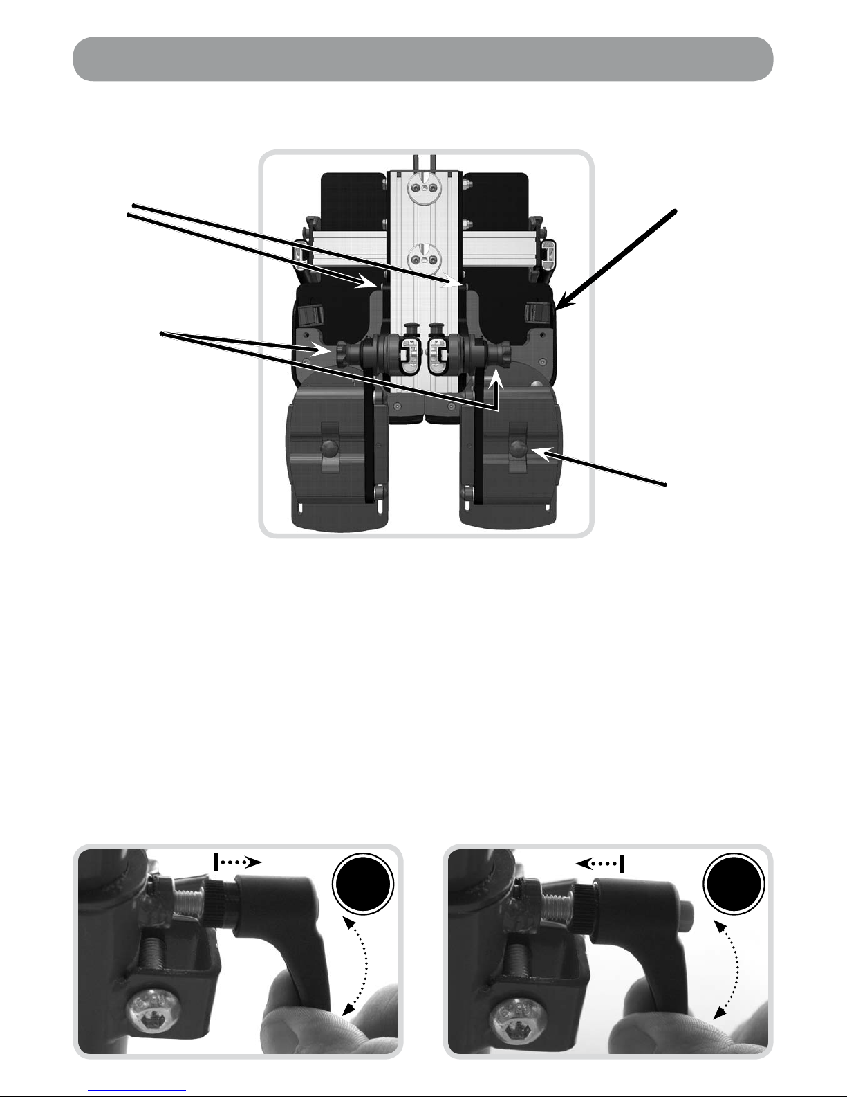
Hip Pad Adjustment
Hip Pad Width
• Loosen Locking Bolt A by one full turn using the 4mm Allen Key Provided
• The Hip Pad can now be freely moved along the width adjustment rail B.
• Set the desired position and then re-lock the fixing screw to secure the pad in place.
Hip Pad Angle (Where Fitted)
• To set the angle of the pad you should loosen the securing handwheel C by rotating a
couple of turns in an anti-clockwise motion.
• Once released the pads can be positioned by pressing down on the handwheel whilst
simultaneously altering the angle of the pad using your other hand.
• Once the desired position has been achieved you should release the handwheel and
re secure it by turning in a clockwise direction until hand tight.
B
A
C
Pad Angle – As an Alternative you can position the pad without pressing
down the handwheel, though this has potential to shorten the life of the
locking mechanism and is therefore not recommended)
!
Page 20

20
A
B
Inner Thigh Pad Fitting &
Adjustment
• To fit the inner thigh pads, Screws
A complete with Washers B should
be inserted through the carrier plate
and into the dedicated holes on the
underside of the Seating Unit.
• Tighten each screw using the 4mm
allen Key provided.
• Once held on (but not fully locked
off) you can continue to set the other
adjustment.
Abducting the legs
• With Screws A still loose, rotate the
inner thigh pad to the desired position.
• Once attained, lock off screws using
the 4mm Allen Key provided.
Flip Down the Inner Thigh Pad
(To facilitate Transfers)
• Press and Hold Button C, whilst
flipping down the inner thigh pad.
• To reengage the inner thigh pad,
simply rotate back up and into place
until it latches securely.
These pads enable you
to sit the client in an
abducted position which
can help to lower muscle
tone, create a wider sitting
base and maintain the
hips in a good position.
C
Thigh Pad Adjustment
Page 21

21
A
B
Outer Thigh Pad Fitting & Adjustment
• To fit the outer thigh pads, Screws A complete with Washers B should be inserted
through metal adductor bracket into the dedicated holes on the plastic carrier plate.
• Tighten each screw using the 4mm Allen Key provided.
• Once held on (but not fully locked off) you can continue to set the other adjustment.
Adducting the Legs / Setting Channel Width
• With Screws A still loose, slide the outer thigh pad along it fixing slot to the desired
position.
• Once attained lock off screws using the 4mm Allen Key provided.
Page 22

22
Headrest Adjustment
Always check that the headrest is secure and the wings are not tight around
the head. The headrest wings are ideally set at 45 degrees to the back.
!
Adjusting the Wing Angle
This adjustment point allows you to move the wing position to offer more side support to
the head. This adjustment point allows you to alter the angle of the headrest to support
the head and neck.
• Unzip the headrest cover at the back and loosen the lock lever (A).
• Adjust the sides of the headrest into the desired position.
• After desired position has been reached tighten the bolts to secure in place.
Perform this for either side wing of the headrest.
Adjusting the Headrest Angle
• Levers (B) should be operated together to achieve the desired head positioning of the user. Loosen
the levers by turning anti-clockwise.
• Once loose, the head support angle can be manually adjusted to suit the user.
• Tighten the levers to secure in place.
Adjusting the Headrest Height
• Loosen the hand wheel (C)
• Slide the headrest up or down inside the bracket on the back of the chair.
• Re tighten the hand wheel to secure in place.
A
C
B
Page 23

23
Height & Width of Supports
• Loosen both bolts (A) using the allen key provided.
• Slide the pads up or down along the slot in the seat back (B) to adjust the height.
• Slide the pads horizontally to adjust the width.
• Re tighten the allen key bolts to secure.
Flip Away Action
(Where Fitted)
• Pull plunger (C) downwards.
• Flip the supports away to aid transfer or set up.
• When ready push the supports back in, until they lock in place.
A
B
C
Check that the supports are not too high under the arms of the user or tight
around chest area by running your fingers around the inside of the supports.
Also check that the supports do not infringe on any feeding tubes.
!
Lateral Support Adjustment
Page 24

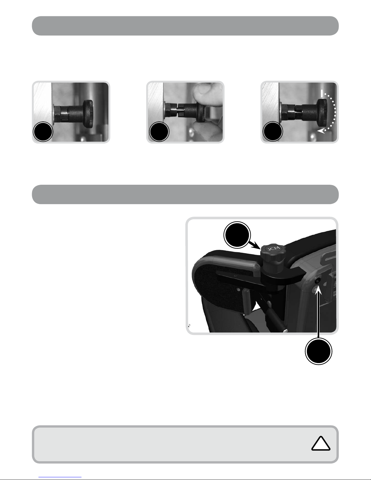
24
Adjusting Arm Height
• (A) highlights the plunger which is used to
adjust the height of the arms and therefore
in turn the height of the tray.
• Pull plunger (A) outwards away from the
arm, and while holding the lever open
slide the arm up or down, selecting one
of the holes which come into view as you
raise the arm up from its lowest position.
• When a suitable position has been
acquired, lock the arm into place by
releasing the lever, ensuring it fits securely
back in place.
Adjusting Arm Angle
• To set the angle of the arm top you should
loosen the securing handwheel (B) by
rotating a couple of turns in an anticlockwise motion.
• Once released the arm top can be
positioned by pressing down on the
handwheel whilst simultaneously altering
the angle using your other hand.
• Once the desired position has been
achieved you should release the
handwheel and re secure it by turning in a
clockwise direction until hand tight.
Removing The Armrest
(Facilitates Side Transfer)
• To remove the arm rests entirely (complete
with the attached hip pad), pull plunger
(C) outwards and hold in the outward
position with one hand. Use your
other hand to lift the complete arm rest
assembly upwards away from the seat.
• To replace, reverse the operation, lowering
the arm rest assembly back onto the
fixation plate (D), holding open the
plunger to allow it to engage fully before
releasing the plunger to lock the arm back
into position.
Arm Rest Adjustment
D
Arm Top Angle – As an Alternative you can position the
Arm Top without pressing down the handwheel, though
this has potential to shorten the life of the locking
mechanism and is therefore not recommended)
Always ensure
that the arms are
securely fixed before
using the chair.
The plunger (A) should pull out freely,
if resistance is felt ensure no weight is
being put through the arm rest.
! !
!
A
C
B
Page 25

25
Note:
When fitted with Split Leg Stems/Footplates, it is possible to set the angle for both left
and right stems independently. To do this follow the instructions below for each leg stem.
Legrest Adjustment & Removal– Split Option
Angle Adjustment
• Pull and Hold Out plunger A with
one hand before adjusting the
legrest angle with your other hand
to the desired angle.
• When you have achieved the
desired position, release the
plunger to secure in the next
available locking position.
• Ensure the plungers are securely
located in position.
Removing the Leg Stem
(Facilitates Standing Transfer)
Note: Removal of the Footplates
can also help when packaging for
transportation or when the seat is to
be utilised on a chassis with its own
integrated footplates.
• To Remove the Leg Stems Entirely
(complete with the attached
footplate), remove safety boss B
using the 4mm Allen Key Provided.
• Once removed, Pull and Hold Out
Plunger A with one hand, using your
other hand to rotate and pull away
the Leg Stem entirely from the main
seating unit.
• To replace, reverse the operation,
locating the leg stem onto the
fixation Hook C, holding open the
plunger to allow it to engage fully
before releasing the plunger to lock
the leg stem into position.
• Finally refit the safety boss using the
4mm Allen Key provided.
A
B
Page 26

26
C
Foot Positioning Adjustment
D
A
B
C
E
Fooplate Angle Adjustment
• To set the angle of the footplate you
should loosen the securing handwheel
A by rotating a couple of turns in an
anti-clockwise motion.
• Once released the Footplate can
be positioned by pressing down on
the handwheel whilst simultaneously
altering the angle using your other
hand.
Once the desired position has been
achieved you should release the
handwheel and re secure it by turning in a
clockwise direction until hand tight.
Flipping Up the Footplate
(Facilitates Standing Transfer)
• Press in Button B with one hand, using
your other hand to flip up the footplate.
• To flip back down, simply rotate the
footplate down until it latches back into
place.
Footplate Height
• Pull and hold open Plunger C, whilst
maintaining hold of the footplate with
your other hand.
• Once disengaged, the footplate stem
should be free to slide up and down the
legrest stem.
• Slide to the desired position before
releasing the Plunger to engage it
within the closest available location
hole.
• Ensure the plunger is fully engaged
before commencing use of the chair.
Foot Holder Positioning
Note: The Foot Holder/Plate can be
adjusted for Foot Size, Fore & Aft, Side to
Side (width between feet) and Foot Angle
(in conjunction with Ab/Adduction) Each
of these adjustments is covered below.
Foot Size
• Turn locking screws D anti-clockwise
half a turn using the 4mm Allen Key
provided
Page 27

27
Footplate Angle – As an Alternative you can position the Footplate without
pressing down the handwheel, though this has potential to shorten the
life of the locking mechanism and is therefore not recommended.
Plunger C should pull out freely, if resistance is felt ensure no
weight is being put through the footrest.
!
!
Do not use foot straps unless the client is wearing shoes.
!
• Slide the Heel guide in or out to narrow/widen the space available for the foot.
• Repeat for the opposing Heel Guide if require before re-securing the locking screw D
to hold them in place.
Fore & Aft & Rotation.
• Turn Locking Screws E anti-clockwise half a turn using the 4mm Allen Key provided.
• Slide the entire foot holder forwards or backs whilst simultaneously setting the rotation
of the plate.
• Once the desired position has been acquired re-secure the locking screws to hold
back in place.
Side to Side/Width Adjustment
• Pull and hold open Plunger F,
whilst maintaining hold of the
footplate with your other hand.
• Once disengaged, the footplate
holder should be free to slide
sideways, bringing the feet
together/apart as required.
• When you have achieved the
desired position, you should
release the Plunger to engage
it within the closest available
location hole.
• Ensure the plunger is fully
engaged before commencing
use of the chair.
Foot Straps
Foot straps or ankle huggers can be attached through the slots in the sandal to secure
feet. Feed the strap through the buckle and close the buckle shut to secure.
F
Page 28

28
Setting the Strength of Resistance & Power of Return
For maximum performance and comfort, it is necessary to adjust the
strength of resistance and power of return of the dynamic mechanism.
The resistance is adjusted by varying the air pressure and should be
determined by the user’s weight, seating position, seat design and
personal preference.
The air pressure is adjusted with a standard schrader valve shock
system pump (A) on the main air valve of the dynamic mechanism.
Strong Resistance Increasing the Air Pressure
The shock system is more difficult to compress
during use. The seat back feels firmer when
pushed against.
• Attach the pump to the air
valve on the back of the
dynamic mechanism (B).
• Pump air into the valve to
increase pressure.
• Watch the pressure valve dial
on the pump to determine the
amount of pressure added.
Weak Resistance Decreasing the Air Pressure
Makes the shock system compress more easily.
The seat back feels softer when pushed against.
• Press button (C) on the pump and keep
depressed until the air pressure resistance
achieves required level.
B
A
C
Setting Up the Dynamic Back Mechanism
Never modify your shock system. Modification, improper service or use of non-SR
SUNTOUR spare parts voids the warranty and could cause a malfunction resulting
in serious injury.
Follow the maintenance schedule, if the shock system shows any malfunctions such as
losing oil, making unusual sounds or any part is bent or broken, cease use of the seating
system immediately and contact JCM for assistance.
Never try to open or disassemble the shock system. Opening the shock system could
cause serious injury.
!
The pressure range is 50-250psi. Never exceed an air pressure of 250psi in
the uncompressed shock system. Exceeding the maximum air pressure of
250lbs/inch could result in serious injury.
!
Page 29

29
Setting the Power of Return
The power of return controls the rate at which the
shock system decompresses or rebounds. The
amount of return strength needed depends on the
user’s weight, the spring rate which is set by the air
pressure, the amount of use, the sitting style and
personal preferences.
The best way to adjust the return strength is to
decrease it completely by turning the red adjuster
wheel (D) clockwise (labelled slow) and test by
placing the user in the seat. Increase the damping by
slowly turning the wheel counter clockwise (labelled
fast) until the user feels comfortable and safe without
the suspension kicking the user too far forward.
Disengaging the Mechanism
Occasionally at meal times etc it is necessary to
disengage the dynamic mechanism. To do this:
• Lock the system by switching the lever from the
“ open “ to “locked” position on the lever on the
shock system.
• The mechanism should not be left in the ‘locked’
position as part of normal use. You should ensure
the mechanism is returned to the ‘open’ position
once the activity demanding the lock out has
been completed.
Maintenance Schedule:
The rear shock systems need a minimum of maintenance only:
• Use water and soap only to clean the system - never use a high pressure washer or any water under
pressure to clean the shock system as water may enter the system.
Before every use:
• Check air pressure (it is normal for the shock system to lose air pressure slightly over time) - Check
to ensure it is appropriately set for your client.
• Adjust power of return set up to ensure it is set appropriately for your client.
D
Speed
label
The extensive service of the shock system internals
must only be done by an authorized technician.
WARNING!
Please note that your SR SUNTOUR rear shock is filled with oil and nitrogen. This
makes it impossible to open the rear shock without having the knowledge and special
tools required to carry out this task. Please do not try to open the rear shock for service
issues, this implies a very high risk of getting seriously injured. Besides this you will not
be able to reassemble the shock any more. Opening the shock will void its warranty.
If there is a problem with your rear shock, cease use of your chair immediately and
contact JCM Seating Solutions.
!
Page 30

30
Castors •Lift base and check each wheel to ensure it is not damaged, loose or worn.
Brakes
•Removing any grease or dirt that has built up on the wheels, check that the brakes
stop the wheels rotating.
•Check they are securely fixed in place & that there are no signs of damage or wear & tear.
Pushing
Handles
•Ensure handles are functioning correctly.
•Check there are no signs of damage or wear and tear.
•Ensure push handle grips are secure.
Seat Tilt
In Space
Mechanism
•With the tilt lock released check for free movement with no signs of damage or wear
to the mechanism, lever or cables.
•Tighten the lock and ensure it holds the seat angle.
Base Height
Adjustment
•With the seat unloaded, press the lever & ensure it moves freely to the maximum height.
•In incremental stages add weight up to the maximum load (40, 60, 80 or 100kgs)
and, over a period of time (approx 10 - 15 minutes), check that there is no creep
(lowering) of the seat. If it is not practical to perform this test, as a minimum
requirement, immediately following the maintenance check, the static position of the
seat should be monitored whilst a user is positioned in the system.
•With the load on, press the lever & ensure the seat travels freely to the lowest position.
Seat /
Backrest
Upholstery
•Check the attachment points of the seat and backrest upholstery are tight.
•Check for worn covering. Rough worn upholstery can cause discomfort, would be
difficult to keep hygienically clean, and may cause skin irritation.
Interface
•Check there are no signs of damage or wear and tear.
•Ensure the function secures the seating unit properly.
Frame
With correct
maintenance the
frame should
provide at least
5 years trouble
free use but,
depending on
conditions of use,
wear will occur
and a thorough
inspection is
recommended.
•Check all metal parts to ensure there are no signs of damage or wear and tear,
paying particular attention to adjustable or moving parts.
•Check there are no signs of failure in joints and welds.
•Check tightness & security of all fixings, bolts, nuts, spring loaded pegs, & other fitments.
•Check for signs of fatigue wears, replace parts that show signs of wear or repeatedly
becoming loose.
•ANCHOR POINTS (where applicable) for transportation must be checked to ensure
security, check there are no signs of damage, wear and tear or failure.
Fixtures
•Check arm pads and headrest and replace if worn.
General maintenance should be carried out by a competent, professional person who is well informed
on how to use the equipment (see warranty - page 33) if there is no such person available or a more
thorough check is needed, a service via an approved repairer (see opposite) should be booked. The
person who carries out the maintenance check or service should always fill out the service history log
record (page 32) in order to ensure the warranty remains valid.
As documented opposite, the degree of maintenance required is dependant on various factors relating
to the use of the product. In addition to the specific functional adjustment warnings specified in this
manual, it should be ensured that a thorough inspection of the following should be completed at no
greater than 6 month intervals: (Points listed here are generic across the JCM range and do not apply to
all products).
Cleaning & Care
We recommend the following points for successful cleaning of your equipment. (It is possible that some
surface wrinkling may occur following these processes)
Fabric Upholstery Care
Refer to JCMs seperate fabric cleaning guide which can be found on their website www.jcmseating.
co.uk or in hardcopy format from the JCM office. Do not use bleach, acidic, solvent, abrasive, biological
or phenolic based cleaners.
Metal Framework
• If all upholstery is removed the metal framework can be cleaned with hot soapy water and detergent
or it can be steam cleaned. (Labelling may need to be replaced following steam cleaning).
• Ensure that the framework is thoroughly dried after cleaning.
• Always ensure that any moving or adjustable parts are re-lubricated.
General Maintenance
!
Page 31

31
Servicing via Approved Repairer
What should be completed during a service?
A service is a comprehensive combination of inspection, maintenance and repair or
replacement of worn, faulty or missing components. The growth and any changes
of the occupants needs since the original assessment is taken into account when
performing the service. This is in contrast to general maintenance (opposite), where only
straightforward checks, inspections and adjustments take place and primary services are
planned.
What happens if a fault is found?
If any faults are found that could prove to be a risk to either the user or the operator
then all use of the equipment should be ceased immediately until the product has been
repaired.
Who should carry out the service?
It is stressed that only a JCM approved repairer or a person with competent training of a
Class 1 medical device should carry out this work.
Any modifications must not be carried out without prior agreement of JCM Seating
Solutions Ltd. It must be understood that unauthorised modifications may pose a risk to
users and attendants. Unauthorised modifications will also invalidate the warranty.
Any new parts required should be genuine JCM Seating Solutions Ltd. approved parts,
fitted to JCM specifications.
Frequency of Service
JCM recommend that a service of this product is completed once every 6 months as a
minimum. However, the frequency of inspection and service must be altered depending
upon the severity of use. If the system is used in any of the following ways then the
use could be said to be fairly heavy and constant. Therefore we would recommend the
service interval be reduced to once every three months;
• Daily for around 8 to 10 hours.
• Weekly for at least 6 days out of 7.
• Monthly for at least 11 months a year.
• By an active user or somebody who is very active voluntarily or involuntarily.
• By a user who is above 80% of the maximum user weight recommended.
• Transported in a moving vehicle twice or more in a day.
If the usage exceeds the amount highlighted above it is possible that services every six
weeks or less might be needed.
How To Book A Service
JCM have specified technicians trained to service our products. If you would like JCM to
service your chair or for further information please contact us on 01733 405830.
Alternatively, contact the person who issued you with the product.
Page 32

32
Date Service Performed Organisation Print Name & Sign
Service Record Log
Seating system serial number ___________________
Date delivered ______/______/______
Battery use by date ______/______/______
This log is an important record of usage and care of the product. It is a primary tool in
predicting the need for further service and maintenance. It should be completed each
time an inspection, service or any other significant manipulation has taken place. JCM
Seating Solutions Ltd. will require proof of service for any warranty claims or orders.
Please contact JCM if additional log sheets are required.
Page 33

33
Warranty
IMPORTANT
JCM Seating Solutions Ltd. will not be held responsible for any damage or injury caused by incorrect
use of this product. For any information or guidance on the use of this product please call our office who
will put you through to your local representative or send you any additional information you may require.
Tel: 01733 405830
3 YEAR WARRANTY
Products manufactured by JCM are covered
with a manufacturers 3 year warranty.
What it Covers
The warranty covers all aspects of product failure
due to faulty workmanship or manufacturing.
Period of Cover
The period of the warranty runs for 3 years from
the date that the product is dispatched.
The Work JCM is Obliged to Complete
JCM’s obligation under this warranty is to replace
or repair any defective goods within the period of
the warranty free of charge.
What the Warranty Does Not Cover
• Items that are damaged or fail due to natural
wear and tear, extreme usage, neglect or misuse.
• Accidental damage, modifications or repairs
carried out by a third party unauthorized by JCM
or non professional healthcare representative.
Customer Responsibility
To ensure the warranty remains valid, customers
are advised that servicing, maintenance and
re-issuing guidelines must be followed and
documented as stated in the manual.
JCM will require proof of service (see opposite) for
any warranty claims or orders.
When making a claim JCM reserve the right
to inspect the product and all necessary
documentation.
Only valid for products purchased after 1st April 2006. Applies only to
products exclusively manufactured by JCM.
W
A
R
R
A
N
T
Y
M
A
N
U
F
A
C
T
U
R
E
R
3
YEAR
3 YEAR WARRANTY
Page 34

34
Most JCM Seating Solutions Ltd. products are individually assessed for a client prior to
issue. They are handed over in a controlled way to ensure optimum fit and specification,
checks are completed and any additional individual verbal instructions given. We
therefore recommend the following points are adhered to prior to any re-issue of
equipment:
• Cleaning
Follow a rigorous process of cleaning in order to decontaminate the product and
eliminate the chance of cross infection.
• Assessment of Fabrics / Foams
Carefully assess the condition of fabrics and foams in the seating product, and have
these replaced partially or even completely if need be. In severe cases if the chassis
is worn and the seating in poor condition it may be necessary to have the product refurbished by the manufacturer. In very severe cases if the chassis is badly worn and
the seating in very poor condition then the product should be decommissioned and
disposed of.
• Electrical and Electronic Equipment Decomissioning
If your product is set up with an electrical function you should always contact JCM or
your authorised representative for de-comissioning information.
• Appropriateness of Equipment
Check that the equipment supplied is appropriate for the needs of the user taking age,
weight, ability, diagnosis, and any other important factors into account. For instance,
JCM Seating Solutions Ltd. products may not be suitable for persons with severe
challenging patterns of behaviour. Also ensure safe specified limits for use are not
exceeded by the new user. Your sales representative can advise on the suitability of
the equipment.
• Manuals and Records
Ensure this instruction manual and any additional manuals for the seating unit are
handed over to the new user with the equipment and ensure the servicing log history
is up to date. Records on the new user must be updated to maintain traceability.
• Inspection
The equipment should have a rigorous inspection prior to the reissue, to include the
points covered in the six monthly routine check, regardless of if the checks were
recently completed. The equipment should be free of excessive wear or distortion in
any aspect of its main construction or accessories.
• Condition
Wheels, tyres and brakes must be in good working condition, properly adjusted and
Inspecting & Reissuing of Equipment
Page 35

35
inflated as appropriate.
• Accessories
Check all accessories carefully for damage and potential shortcomings which may
pose a risk to the user.
• Function
Ensure that all the functions of the chair are working correctly e.g. tilt in space, height
adjustment, back recline, folding etc.
• Fixings
Check that any knobs, hand wheels, nuts, bolts, levers and fixings are in good
condition and fitted in place securely.
• Modifications
Any special modifications, adaptations, alterations or other such procedures including
added accessories may require review. If they are found inappropriate, remedial action
(if considered safe and practical) should be taken to reverse them if possible.
• Labelling
Any labelling specific to the previous user should be removed and replaced with
labelling specific to the new user.
• Adjustment
Adjustment of the equipment to the new user must be carried out by suitably qualified
and experienced professionals. These adjustments along with the other appropriate
checks and tests should be completed with the owners knowledge and agreement.
• Hand Over
Competent handing over of the equipment to the new user or attendant must include
proper training and advice in safe use, particularly regarding transportation issues.
• Packaging
Always ensure that the chair is packaged correctly before delivery.
• Handle Fitting
Please note that the handle fitted is dependent on the size of the chair. You therefore
need to ensure the size label on the handle matches the size of the chair being used.
Page 36

www.jcmseating.co.uk
Q.A.34 (Jan 2013)
15 -18 Maxwell Road,
Woodston Industrial Estate,
Peterborough,
Cambridgeshire
PE2 7HU
Tel: 01733 405830
Fax: 01733 405838
Email: enquiries@jcmseating.co.uk
© 2013 JCM Seating all rights reserved.
 Loading...