

Page 1

Support: http://www.jcmglobal.com/en/contact/default.aspx Web-Site: http://www.jcmglobal.com
Taiko™ Series
Banknote Acceptor
(PUB-7/11)
Operation and Maintenance
Manual
(Revision 4)
P/N 960-100175R_Rev. 4 {EDP #200824}
Issue #4045-SME-01-04
© 2013, Japan CashMachine Co., Limited
Page 2

Taiko™ Series Banknote Acceptor
or
or or
or
E142330, Subscriber 857947001, Vol. 2
Issue #4045-SME-01-04
REVISION HISTORY
Rev №. Date Reason for Update Comment
A 7/12/10
12/14/11
28/17/11
3 4/09/12
4 3/25/13
Initial Version
Barcode Coupon Specification Added
Important corrections made to Tables in Section 2.
Added Waffletechnology Cleaning Card availability & Useage
information in Section 2, corrected Part Number Information in
Section 7 and added 2 Tables to Appendix A.
Added EBA Type Bezel in Section 7.
International Compliance
• RoHS Directives
• UL & c-UL Marks
• CE Mark .
This product document (hereinafter referred to as “Manual”) is fully covered by legal Copyrights owned by the Japan
Cash Machine, Co., Ltd., (hereinafter referred to as “JCM”) under Japanese laws and foreign countries. This Manual
contains many copyrighted, patented, or properly registered equipment items manufactured by JCM, that are prohibited
and illegal to duplicate, replicate, or copy in whole, or in part, without the express
authorization by JCM with the following exceptions:
1. When an authorized JCM agency or distributor duplicates the Manual for sales promotion and/or service
maintenance of the product, or technical service personnel education as required; and
2. When an end user duplicates the Manual to maintain operation of the product or operate the product in general.
JCM retains all rights to amend, alter, change or delete any portion of this Manual in whole, or in part, or add items
thereto without notice regarding the product or its related products.
JCM is a registered trademark of Japan CashMachine Co, Limited. All other product names mentioned herein may be
registered trademarks or trademarks of their respective companies. Furthermore,
in each case throughout this publication.
Copyright © 2013 By Japan CashMachine Co, Limited
™, ® and © are not always mentioned
Page 3

i
Taiko™ Series
Banknote Acceptor
Table of Contents
TOC
Page
1 GENERAL INFORMATION.................................................................................. 1-1
Description .................................................................................................................. 1-1
Taiko PUB-7/11 Unit .................................................................................................... 1-1
Model Descriptions .................................................................................................... 1-2
Precautions ................................................................................................................. 1-2
User Cautions ...........................................................................................................................1-2
Installation Cautions ..............................................................................................................1-2
Mounting, Dismounting & Transportation ...............................................................................1-2
Preventive Maintenance ........................................................................................................1-2
Banknote Fitness Requirements ............................................................................................1-3
Primary Features ........................................................................................................ 1-3
Product Label .............................................................................................................. 1-4
Component Names ..................................................................................................... 1-5
Specifications ............................................................................................................. 1-6
Technical Specifications ...........................................................................................................1-6
Environmental Specifications ...................................................................................................1-6
Electrical Specifications ............................................................................................................1-7
Structural Specifications ...........................................................................................................1-7
System Configuration ................................................................................................ 1-7
Unit Dimensions ......................................................................................................... 1-8
Taiko PUB-7 Standard Bezel Unit Outside Dimensions ............................................................1-8
Taiko PUB-7/11 Unit Clearance Dimensions ..........................................................................1-8
Taiko PUB-11 Standard US Bezel Unit Outside Dimensions ....................................................1-9
International Compliance ......................................................................................... 1-10
Technical Contact Information .................................................................................1-11
Americas & Oceania ...............................................................................................................1-11
JCM American ..................................................................................................................... 1-11
Europe, Africa, Russia & Middle East .................................................................................... 1-11
JCM Europe GmbH ............................................................................................................. 1-11
UK & Ireland ...........................................................................................................................1-11
JCM Europe (UK Office) ......................................................................................................1-11
Asia ........................................................................................................................................1-11
JCM Gold (HK) Ltd. .............................................................................................................1-11
Japan Cash Machine Co, Limited (HQ) ............................................................................... 1-11
2 INSTALLATION ................................................................................................... 2-1
Installation and Removal ........................................................................................... 2-1
Installing the PUB-7/11 Taiko Bezel ..........................................................................................2-1
Power Harness Wiring Procedure ............................................................................................ 2-2
Clearing a Banknote Jam ........................................................................................... 2-2
Clearing an Upper Area Banknote Jam ....................................................................................2-2
Clearing a Lower Area Banknote Jam ...................................................................................... 2-3
DIP Switch Configurations ........................................................................................ 2-3
Denomination Setting Mode ..................................................................................................... 2-4
Accept Setting Mode ..............................................................................................................2-4
P/N 960-100175R_Rev. 4 {EDP #200824} © 2013, Japan CashMachine Co., Limited
Page 4

ii
Taiko™ Series Banknote Acceptor
Table of Contents
Page
Inhibit Setting Mode .............................................................................................................. 2-4
LED Pattern Setting Mode .......................................................................................................2-4
Defining Pattern 1 ................................................................................................................. 2-4
Defining Pattern 2 ................................................................................................................. 2-4
Encryption Code Initialization Setting Mode ............................................................................ 2-5
Error Codes & Conditions ......................................................................................... 2-5
Interface Connector Pin
Assignments ............................................................................................................... 2-5
Cleaning Procedures ................................................................................................. 2-6
Sensor and Roller Cleaning Procedure ................................................................................... 2-6
Available Cleaning Card ............................................................................................ 2-6
Card Features .......................................................................................................................... 2-6
Directions For Use ................................................................................................................... 2-6
Taiko Sensor and Roller Locations ........................................................................... 2-7
Operational Check ...................................................................................................... 2-7
Standard Interface Circuit Schematics ..................................................................... 2-9
Standard Interface Circuit Schematics (Continued 1) ............................................................ 2-10
Standard Interface Circuit Schematics (Continued 2) .............................................................2-11
Standard Interface Circuit Schematics (Continued 3) ............................................................ 2-12
Standard Interface Circuit Schematics (Continued 4) ............................................................ 2-13
Operational Flowcharts ............................................................................................ 2-15
Operational Flowcharts (Continued) ...................................................................................... 2-16
3 COMMUNICATIONS ............................................................................................ 3-1
Americas & Oceania ................................................................................................................ 3-1
JCM American ....................................................................................................................... 3-1
Europe, Africa, Russia & Middle East ...................................................................................... 3-1
JCM Europe GmbH ............................................................................................................... 3-1
UK & Ireland ............................................................................................................................ 3-1
JCM Europe (UK Office) ........................................................................................................ 3-1
Asia .......................................................................................................................................... 3-1
JCM Gold (HK) Ltd. ............................................................................................................... 3-1
Japan Cash Machine Co, Limited (HQ) ................................................................................... 3-1
4 DISASSEMBLY/REASSEMBLY ..........................................................................4-1
Tool Requirements ..................................................................................................... 4-1
Primary Unit Disassembly ......................................................................................... 4-1
Bezel Guide Removal .............................................................................................................. 4-1
CPU Circuit Board Removal .................................................................................................... 4-1
MAG Board Removal (PUB-11 Only) ....................................................................................... 4-2
Sensor Circuit Board Removal ................................................................................................ 4-2
Transport Drum Disassembly .................................................................................................. 4-2
Encoder Board and Drive Motor Removal ............................................................................... 4-3
Entrance and Exit Solenoid Removal ...................................................................................... 4-4
5 WIRING DIAGRAMS ............................................................................................ 5-1
PUB-7 System Wiring Diagrams ............................................................................... 5-1
PUB-7 System Wiring Diagrams (Continued) .......................................................................... 5-2
PUB-11 System Wiring Diagrams .............................................................................. 5-3
PUB-11 System Wiring Diagrams (Continued) ........................................................................ 5-4
P/N 960-100175R_Rev. 4 {EDP #200824} © 2013, Japan CashMachine Co., Limited
Page 5

iii
Taiko™ Series Banknote Acceptor
Table of Contents
Page
6 CALIBRATION AND TESTING............................................................................ 6-1
Workbench Tool Requirements ................................................................................. 6-1
Software Download Preparation ...............................................................................................6-2
Software Downloading Procedure ............................................................................ 6-2
PC Program Installation ...........................................................................................................6-2
Palm Pilot Program Installation ................................................................................................6-2
Writing a New Serial Number .................................................................................... 6-3
Upgrading/Replacing Software .................................................................................................6-3
Programming Requirements ..................................................................................................6-3
Re-Programming Connection Procedure .................................................................................6-5
Serial Number Writer Application Use ......................................................................................6-5
Cloning Units .............................................................................................................. 6-5
Required Items .........................................................................................................................6-5
Cloning Procedures ...............................................................................................................6-5
Calibration Procedures .............................................................................................. 6-7
Calibration Description .............................................................................................................6-7
Calibration Tool Requirements .................................................................................................6-7
When to Calibrate .....................................................................................................................6-7
Initial Settings ...........................................................................................................................6-7
Performance Test Diagnostics .................................................................................. 6-7
DIP Switch Tests ....................................................................................................................6-8
No.1 Transport Motor Forward Rotation Test ...................................................................................... 6-8
No.2 Transport Motor Reverse Rotation Test...................................................................................... 6-8
No.3 Aging Test Procedure ................................................................................................................. 6-8
No.4 Solenoid Test Procedure............................................................................................................. 6-9
No.5 Acceptance Test Procedure........................................................................................................ 6-9
No.6 Entrance Flapper Test Procedure ............................................................................................... 6-9
No.7 Exit Flapper Test Procedure ....................................................................................................... 6-9
7 EXPLODED VIEWS AND PARTS LISTS ............................................................ 7-1
Entire Taiko Unit Exploded View ............................................................................... 7-1
Primary Taiko PUB-7/11 Unit Parts List ....................................................................................7-2
Complete Taiko Unit Exploded View ........................................................................................ 7-3
Complete Taiko PUB-7/11 Units Parts List ...............................................................................7-4
Taiko Bezel Unit Exploded View ................................................................................ 7-8
Taiko PUB-7/11 Bezel Units Parts List ......................................................................................7-9
Taiko EBA Type Bezel Unit Exploded View ............................................................ 7-10
Taiko EBA Type Bezel Units Parts List ...................................................................................7-11
8 INDEX................................................................................................................... 8-1
A TROUBLESHOOTING .........................................................................................A-1
Introduction .................................................................................................................A-1
Troubleshooting Overview ........................................................................................A-1
Fault Table Listings ....................................................................................................A-1
Error Codes and Conditions ......................................................................................A-4
B GLOSSARY..........................................................................................................B-1
P/N 960-100175R_Rev. 4 {EDP #200824} © 2013, Japan CashMachine Co., Limited
Page 6

THIS PAGE INTENTIONALLY LEFT BLANK
Taiko™ Series Banknote Acceptor
iv
P/N 960-100175R_Rev. 4 {EDP #200824} © 2013, Japan CashMachine Co., Limited
Page 7

v
Taiko™ Series
Banknote Acceptor
List of Figures
LOF
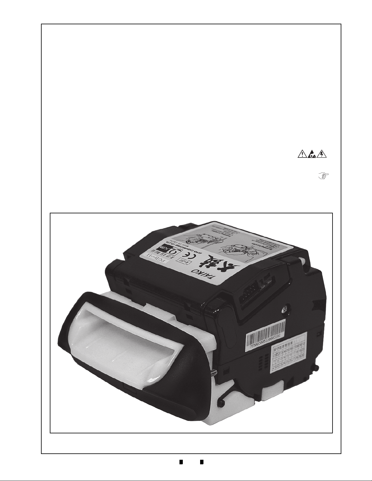
Figure 1-1 Taiko PUB-7/11 Unit .............................................................................. 1-1
Figure 1-2 Precautionary Symbols .......................................................................... 1-2
Figure 1-3 Unacceptable Banknotes ....................................................................... 1-3
Figure 1-4 Installation Simplicity.............................................................................. 1-3
Figure 1-5 Scan Frequency Capability .................................................................... 1-3
Figure 1-6 Taiko Anti-Pullback Feature ................................................................... 1-4
Figure 1-7 Palm Pilot Programmable ...................................................................... 1-4
Figure 1-8 LED Pattern Selectable.......................................................................... 1-4
Figure 1-9 PUB-11 Top Panel Instruction Label...................................................... 1-4
Figure 1-10 PUB-7 Top Panel Instruction Label........................................................ 1-4
Figure 1-11 Taiko PUB-7/11 Component Names...................................................... 1-5
Figure 1-12 Taiko PUB-7/11 System Configuration .................................................. 1-7
Figure 1-13 Taiko PUB-7 Complete Unit Outside Dimensions.................................. 1-8
Figure 1-14 Taiko PUB-7/11 Banknote Acceptor’s Clearance Dimensions .............. 1-8
Figure 1-15 Taiko PUB-11 (US Dollar) Complete Unit Outside Dimensions............. 1-9
Figure 2-1 Taiko Bezel Cut-Out Dimensions........................................................... 2-1
Figure 2-2 Opening Taiko’s Upper Lid .................................................................... 2-1
Figure 2-3 Removing the Taiko Bezel ..................................................................... 2-1
Figure 2-4 Installing the Taiko Bezel ....................................................................... 2-1
Figure 2-5 Mounting the Taiko Bezel ...................................................................... 2-2
Figure 2-6 Installing the Taiko Bezel ....................................................................... 2-2
Figure 2-7 Closing the Taiko Upper Lid................................................................... 2-2
Figure 2-8 Attaching a Taiko Power Connector ...................................................... 2-2
Figure 2-9 Upper Area Banknote Jam Removal ..................................................... 2-3
Figure 2-10 Lower Area Banknote Jam Removal ..................................................... 2-3
Figure 2-11 Left Side DIP Switch Block Location...................................................... 2-3
Figure 2-12 “Accept’ Mode DIP Switch Settings ....................................................... 2-4
Figure 2-13 ‘Inhibit’ Mode DIP Switch Settings ......................................................... 2-4
Figure 2-14 Define Pattern 1 DIP Switch Settings .................................................... 2-4
Figure 2-15 Define Pattern 2 DIP Switch Settings .................................................... 2-4
Figure 2-16 Encryption Mode DIP Switch Settings ................................................... 2-5
Figure 2-17 ID-003/MDB/Pulse Interface Connector................................................. 2-5
Figure 2-18 ID-001 Interface Connector.................................................................... 2-5
Figure 2-19 Sensor Cleaning .................................................................................... 2-6
Figure 2-20 JCM Waffletechnology Cleaning Card................................................... 2-6
Figure 2-21 Taiko Sensor Cleaning Locations .......................................................... 2-7
Figure 2-22 Serial ID-003/MDB Communications Interface Schematic Diagram...... 2-9
Figure 2-23 ccTalk Communications Interface Schematic Diagram ....................... 2-10
Figure 2-24 Pulse Communications Interface Schematic Diagram......................... 2-11
Figure 2-25 Parallel ID-001 Communications Interface Schematic Diagram .......... 2-12
Page
P/N 960-100175R_Rev. 4 {EDP #200824} © 2013, Japan CashMachine Co., Limited
Page 8

vi
Taiko™ Series Banknote Acceptor
List of Figures
Page
Figure 2-26 Parallel ID-062 Communications Interface Schematic Diagram .......... 2-13
Figure 2-27 Taiko Operational Flowchart (Part 1) ................................................... 2-15
Figure 2-28 Taiko Operational Flowchart (Part 2) ................................................... 2-16
Figure 2-29 Taiko Operational Flowchart (Part 3) ................................................... 2-16
Figure 4-1 Taiko Bezel Guide Removal....................................................................4-1
Figure 4-2 Taiko CPU Board Cover Removal............................................................ 4-1
Figure 4-3 Taiko CPU Circuit Board Removal...........................................................4-1
Figure 4-4 Taiko MAG Circuit Board Disconnect.......................................................4-2
Figure 4-5 Taiko MAG Circuit Board Disconnect.......................................................4-2
Figure 4-6 Taiko Side Mounting Screw Removals..................................................... 4-2
Figure 4-7 Upper Lid and Side Covers Removal ....................................................... 4-2
Figure 4-8 Taiko Transport Drum Removal ...............................................................4-3
Figure 4-9 Right & Left Transport Drum End Cover Removal ...................................4-3
Figure 4-10 Dual Feed Roller Assembly Removal..................................................... 4-3
Figure 4-11 Transport Drum Separation....................................................................4-3
Figure 4-12 Upper Guide Prism Removal.................................................................. 4-3
Figure 4-13 Upper Guide Sensor Board Removal.....................................................4-3
Figure 4-14 Motor Drive Assembly Removal .............................................................4-4
Figure 4-15 Encoder Circuit Board Removal ............................................................. 4-4
Figure 4-16 Lower Guide Assembly Removal ...........................................................4-4
Figure 4-17 Lower Guide Assembly Cover Removal................................................. 4-4
Figure 4-18 Lower Guide Lever Removals ................................................................ 4-4
Figure 4-19 Entrance & Exit Solenoid Removal ........................................................4-5
Figure 5-1 PUB-7 12 Volt DC System Wiring Diagram............................................ 5-1
Figure 5-2 PUB-7 24 Volt DC System Wiring Diagram............................................ 5-2
Figure 5-3 PUB-11 12 Volt DC System Wiring Diagram (with Mag) ........................ 5-3
Figure 5-4 PUB-11 24 Volt DC System Wiring Diagram (with Mag) ........................ 5-4
Figure 6-1 Required PUB-7/11 PC Download Workbench Tool ..............................6-1
Figure 6-2 Required PUB-7/11 Palm Pilot Download Workbench Tool................... 6-1
Figure 6-3 Typical Tungsten Series Palm Pilot Handheld with JCM Software
Icons....................................................................................................... 6-2
Figure 6-4 Taiko DIP Switch & Port Location .......................................................... 6-2
Figure 6-5 Taiko PC Download Program Screen ....................................................6-2
Figure 6-6 Taiko Palm Conversion Screen.............................................................. 6-3
Figure 6-7 Taiko Palm Program Download Screen .................................................6-3
Figure 6-8 Taiko Re-Programming Software Tool Connection Configuration ......... 6-4
Figure 6-9 JCM Serial Number Writer Screen ......................................................... 6-5
Figure 6-10 Taiko Clone Software Tool Connection Configuration ...........................6-6
Figure 6-11 Removing Taiko from Bezel Mount ........................................................ 6-7
Figure 6-12 Adjustment DIP Switch Setting...............................................................6-7
Figure 6-13 Reference Paper Insertion .....................................................................6-7
Figure 6-14 Adjustment Complete Paper Ejection.....................................................6-7
Figure 7-1 Entire Taiko Unit Exploded View ............................................................ 7-1
Figure 7-2 Complete Taiko PUB-7/11 Unit Exploded View .....................................7-3
P/N 960-100175R_Rev. 4 {EDP #200824} © 2013, Japan CashMachine Co., Limited
Page 9

vii
Taiko™ Series Banknote Acceptor
List of Figures
Page
Figure 7-3 Taiko PUB-7/11 Bezel Unit Exploded View ..............................................7-8
Figure 7-4 Taiko PUB-7/11 Bezel Unit Exploded View ............................................7-10
P/N 960-100175R_Rev. 4 {EDP #200824} © 2013, Japan CashMachine Co., Limited
Page 10

viii
THIS PAGE INTENTIONALLY LEFT BLANK
Taiko™ Series Banknote Acceptor
P/N 960-100175R_Rev. 4 {EDP #200824} © 2013, Japan CashMachine Co., Limited
Page 11

ix
Taiko™ Series
Banknote Acceptor
List of Tables
Page
LOT
Table 1-1 Taiko PUB-7/11 Model Number Specifications........................................ 1-2
Table 1-2 Taiko PUB-7/11 Technical Specification.................................................. 1-6
Table 1-3 Taiko PUB-7/11 Environmental Specification .......................................... 1-6
Table 1-4 Taiko PUB-7/11 Electrical Specification................................................... 1-7
Table 1-5 Taiko PUB-7/11 Structural Specification.................................................. 1-7
Table 2-1 Power Connector Specifications .............................................................. 2-2
Table 2-2 Typical DIP Switch Settings ..................................................................... 2-3
Table 2-3 Programming DIP Switch Settings........................................................... 2-4
Table 2-4 Red LED Error Code Flash Definitions .................................................... 2-5
Table 2-5 Serial ID-003/MDB Interface Pin Assignments ........................................ 2-5
Table 2-6 ccTalk Interface Pin Assignments............................................................ 2-5
Table 2-7 Pulse Interface Pin Assignments ............................................................. 2-5
Table 2-8 Parallel ID-001 Interface Pin Assignments............................................... 2-6
Table 2-9 Taiko Sensor Type Cleaning Methods..................................................... 2-7
Table 6-1 Test Bench Interface Protocols................................................................ 6-4
Table 6-2 Taiko TEST DIP Switch Settings.............................................................. 6-8
Table 6-3 Aging Test Error Codes............................................................................ 6-8
Table 6-4 Solenoid Error Codes............................................................................... 6-9
Table 6-5 LED Flash Error Codes............................................................................ 6-9
Table 7-1 Primary Taiko PUB-7/11 Unit Parts List................................................... 7-2
Table 7-2 Complete Taiko PUB-7/11 Units Parts List .............................................. 7-4
Table 7-3 Taiko PUB-7/11 Bezel Units Parts List..................................................... 7-9
Table 7-4 Taiko EBA Type Bezel Units Parts List.................................................. 7-11
Table A-1 General Fault Conditions ......................................................................... A-1
Table A-2 Adjustment Fault Conditions .................................................................... A-3
Table A-3 Communication Fault Conditions .............................................................A-3
Table A-4 Taiko Usage Specifications (Part 1)......................................................... A-3
Table A-5 Taiko Usage Specifications (Part 2)......................................................... A-4
Table A-6 Red LED Error Code Flash Definitions .................................................... A-4
P/N 960-100175R_Rev. 4 {EDP #200824} © 2013, Japan CashMachine Co., Limited
Page 12

x
Taiko™ Series Banknote Acceptor
THIS PAGE INTENTIONALLY LEFT BLANK
P/N 960-100175R_Rev. 4 {EDP #200824} © 2013, Japan CashMachine Co., Limited
Page 13
1-1
Taiko™ Series
1 GENERAL INFORMATION
Taiko PUB-7/11 Unit
Figure 1-1 Taiko PUB-7/11 Unit
Banknote Acceptor
Section 1
Description
This section provides a general overview of the
Taiko™ Banknote Acceptor Series (PUB-7/11)
pictured in
designed to help you navigate through this guide
with ease and provides the following information:
• Taiko™ PUB-7/11 Unit
• Component Names
• Model Description
• Type Description
• Software Description
• Precautions
• Primary Features
• Specifications
• System Configuration
Figure 1-1. This first section is
• Unit Dimensions
• International Compliance
• Technical Contact Information.
In order to make operation of this device easier and
make navigation within this manual simpler, the
following illustrations were used within the text:
• Safety Instructions, which need to be
observed in order to protect the operators and
equipment, have been written in bold text and
have been given the pictographs:
• Special Notes, which effect the use of the
Banknote Acceptor, have been written in italic
text and have been given the pictograph:
• Steps, requiring the operator to perform
specific actions are given sequential numbers
(1., 2., 3., etc).
P/N 960-100175R_Rev. 4 {EDP #200824} © 2013, Japan CashMachine Co., Limited
Page 14
1-2
Section 1 Taiko™ Series Banknote Acceptor General Information
Type 1 Type 2 Type 3
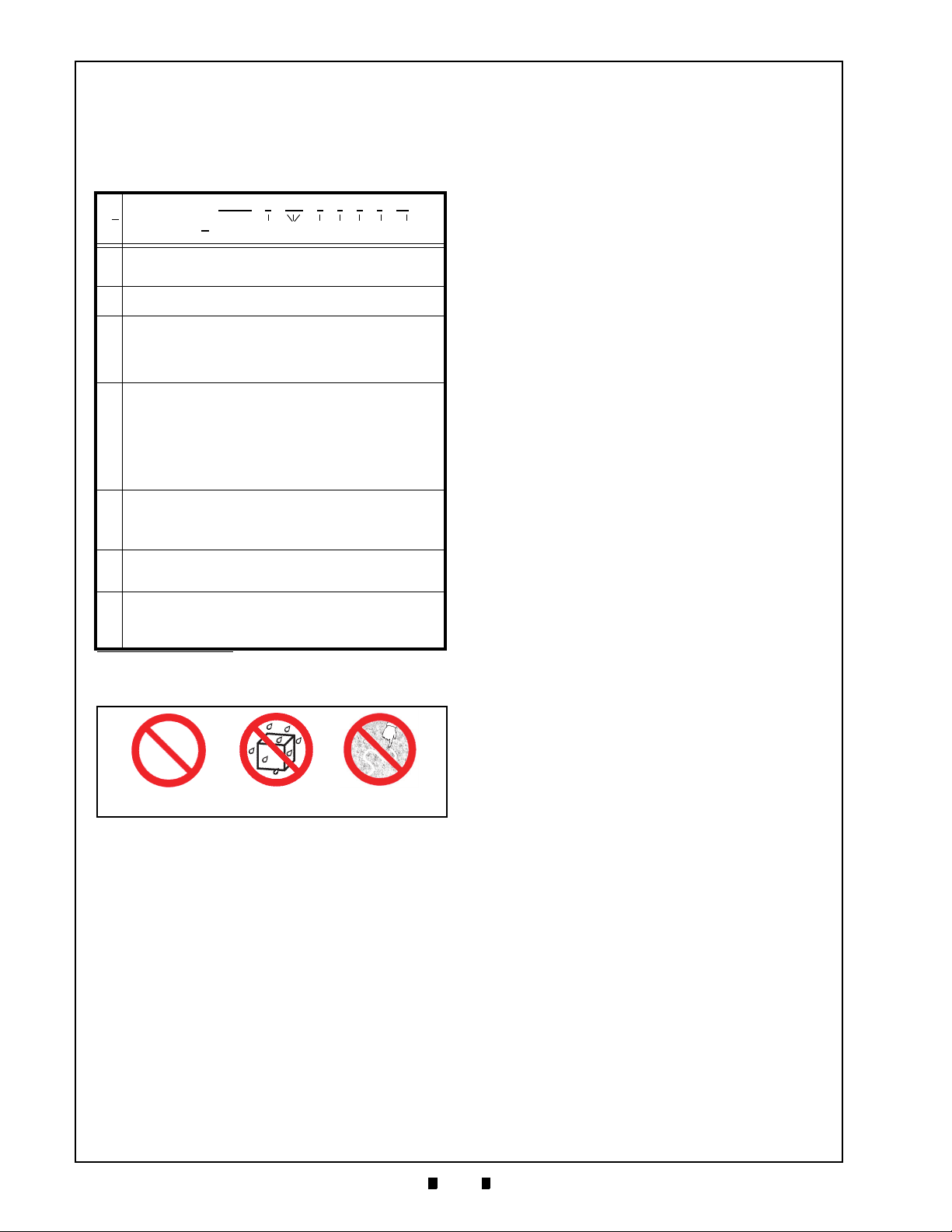
Figure 1-2 Precautionary Symbols
Model Descriptions
Table 1-1 lists the Product Model Number
Descriptions.
Table 1-1 Taiko PUB-7/11 Model Number
Specifications
Model: PUB - * - *** - * - * - * - * - **
o
N
No (1) (2) (3) (4) (5) (6) (7)
Validation Method
(1)
7 = Optical/Transmissive/Reflection
11 = Optical/Transmissive/Reflection/Magnetic (MAG)
Country Code
(2)
Type - ISO 3116 based 3-digit codes
Bezel
0 = No Bezel
1 = Banknote Width Minimum = 67mm/Maximum = 82mm (Euro)
(3)
2 = Banknote Width Minimum = 75mm/Maximum = 82mm (British)
3 = Banknote Width Minimum = 70mm/Maximum = 82mm (China/Taiwan)
5 = Banknote Width Minimum = 66mm (US Dollar)
Optional Unit
0 = Without Optional Unit
1 = With Optional Interface Pin Assignment Conversion Adaptor
Harness Unit (ccTalk Compatible)
2 = Parallel (ID-001) Interface Type (Upper Tray dedicated 16-Pin
(4)
Connector)
3 = Individual Specification
4 = 24V DC Specification
5 = Barcode Coupon Specification
CPU Board Type
0 = Standard
(5)
2 = Interface Pin Assignment (ccTalk Compatible)
3 = Parallel Interface
4 = 24V DC/12V DC
Optional Code
(6)
0 = Standard
1 = Individual Specification
Interface
X4 = ID-003 (Serial)/MDB/Pulse/ccTalk
(7)
01 = ID-001 (Parallel)
03 = ID-003 (Serial) (For Barcode Specification)
62 = ID-062
*. 24V DC is only available when using the Optional 24V DC Version.
*
Precautions
The Figure 1-2 symbols are defined as follows:
1. (Type 1) Do not insert a torn, folded, or wet
Banknote, as this action may cause a Banknote
jam inside the unit.
2. (Type 2) Do not expose the unit to water. The unit
contains several precision electronic devices
which can be damaged if water or any liquid is
sprayed or spilled into the unit.
3. (Type 3) Do not install the unit into a dusty
environment. Dust may affect and degrade the
sensor’s performance.
U
SER CAUTIONS
Careful measures are taken in this product to
ensure its quality; however, the following cautions
should be read and understood by all users in order
to confirm safe operation.
Installation Cautions
The Installation Cautions are defined as follows:
1. Do not allow the Unit to endure or operate at a
high temperature, in high humidity and/or in a
dusty environment.
2. Do not use the Acceptor where temperature variations widely fluctuate.
3. Do not install the Unit into an area where excessive vibration, shock or chemical vapors are present.
4. This equipment is intended for indoor use only.
Be sure that the Host Machine contains enough
protection to avoid wet or dusty conditions when
installing.
5. Avoid exposing the Unit to direct Sunlight and/or
incandescent Lamp illumination having a Gradi
ent Angle of 15 Degree or more, and an illumination index of 3,000 Lux or less.
6. Insure that the Host Machine is designed for
daily operational access such as maintenance
and/or cleaning a Banknote Jam.
7. Be sure to use in the specified power range and
pin assignment. If not, the Unit may be damaged.
8. Be sure to connect the power harness connectors
firmly, otherwise an incorrect input/output con
-
tact failure may occur.
9. Do not pull on the power harness to disconnect
its connector or damage may occur.
10. Do not obstruct the Acceptor’s air holes in order
to provide sufficient cooling to the Unit.
Mounting, Dismounting & Transportation
Methods for Mounting, Dismounting & Transporting the Unit are as follows:
1. Be sure to turn the Power OFF before mounting
or removing the Unit from its permanent loca
tion. Plugging or unplugging Connector Plugs
from their receptacles while the Power is ON
may cause damage to the Unit.
2. When reassembling a disassembled Unit Section,
ensure that each part is properly placed in its
correct location.
3. Be sure to carry the Unit by both hands when
transporting it. Holding the Unit by one hand
may cause personal injury if the Unit accidently
becomes disassembled and falls apart.
4. Be careful not to use excessive outside pressure
on the Unit, or subject it to excessive vibration
during transportation.
5. Do not throw or pound hard on the Unit.
Preventive Maintenance
The Preventive Maintenance requirements are
defined as follows:
1. Be sure the Power to the Unit is OFF before
beginning a Maintenance Procedure. The equip
ment produces improper operating signals while
in maintenance mode that may cause personal
injury.
2. Be sure to remove power to the Unit when opening the upper or lower lid. The active Roller may
cause personal injury.
-
-
P/N 960-100175R_Rev. 4 {EDP #200824} © 2013, Japan CashMachine Co., Limited
Page 15
1-3
General Information Taiko™ Series Banknote Acceptor Section 1
Caution: Do not use any Alcohol,
thinner or citrus based products
for cleaning any surfaces. The
Lenses can become clouded by
chemical effect that may cause
acceptance errors.
Damaged Banknotes
Wrinkled Banknotes
Curled Banknotes
Folded or Partial Banknotes
Figure 1-3 Unacceptable Banknotes
Figure 1-4 Installation Simplicity
Figure 1-5 Scan Frequency Capability
3. Be careful that foreign objects or dust may
intrude the Unit when opening the Guide Area.
4. When closing the Unit, ensure all service door
locks click into place.
5. If the Validator section is dirty due to dust, foreign objects or other such debris adhering to it,
the Banknote acceptance rate will degrade.
Clean the Unit once a month to keep its performance stable.
6. Use a soft, lint-free cloth, Cotton swab or Compressed Air spray to clean dust and debris from
the Banknote transportation path.
7. Perform cleaning and maintenance regularly
when using the equipment in a place where
excessive Automobile exhaust emission or Ciga
rette Smoke may exist.
8. Be sure that the Guide or individual Unit Sections are properly placed in their correct location
following a maintenance procedure.
9. Do not redesign or disassemble the Unit. Unauthorized use by inadequately trained personnel,
or use outside the original manufacture’s intent
for operation voids the warranty.
Banknote Fitness Requirements
1. The following Banknote types may not validate
correctly, or can cause a Banknote jam and/or
damage to the Unit’s Transport path. Banknotes
exhibiting the conditions listed below and illus
trated in Figure 1-3 should be avoided:
• Having perforated or torn areas
• Having excessive folds
• Wet or damp
• Having excessive wrinkles
• Shabby/warn condition
• Adhering foreign objects and/or oil.
Primary Features
The Taiko™ PUB-7/11 Series of Banknote Acceptors contains the following primary features:
• Installation and removal of a TAIKO Unit is
-
-
very easy because of its clip-on style. Anyone
can install a TAIKO Unit quickly.
• Data scanning frequency can be selected by
setting DIP Switches. Scanning once or twice
is selectable. The acceptance rate can be
improved by setting it to scan twice.
P/N 960-100175R_Rev. 4 {EDP #200824} © 2013, Japan CashMachine Co., Limited
• This JCM patented Anti-Pullback Mechanism
provides powerful protection against Banknote
stringing (fishing). The drum rotates every
time a Banknote passes through the Unit, and
tangles any foreign object attached to the
Banknote such as string and/or tape around
itself.
• One of five rotations is DIP Switch selectable.
The greatest fishing protection is obtained by
selecting the five rotation setting.
Page 16
1-4
Section 1 Taiko™ Series Banknote Acceptor General Information
Figure 1-6 Taiko Anti-Pullback Feature
Figure 1-7 Palm Pilot Programmable
Figure 1-8 LED Pattern Selectable
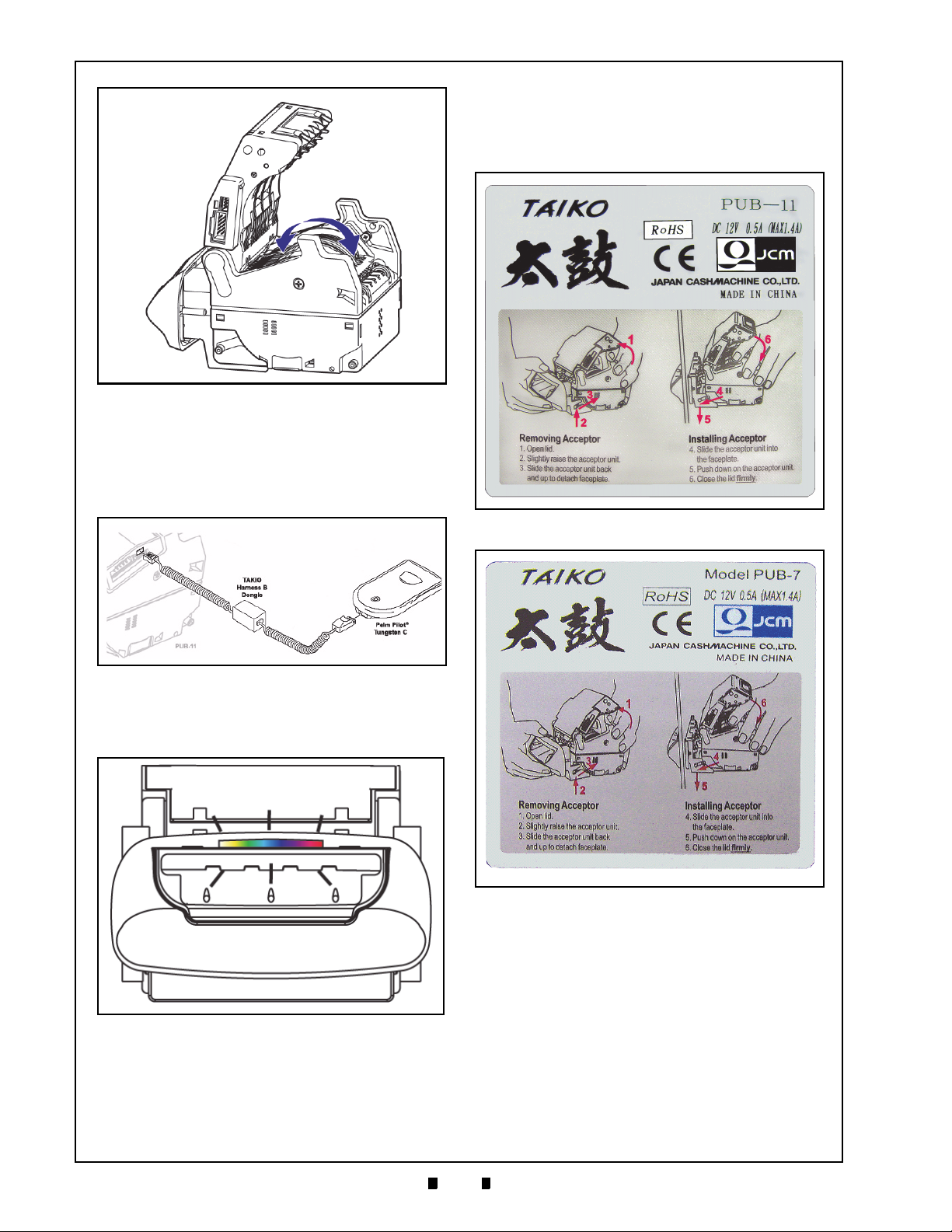
Figure 1-9 PUB-11 Top Panel Instruction Label
Figure 1-10 PUB-7 Top Panel Instruction Label
Product Label
Figure 1-9 and Figure 1-10 illustrates the simple
installation instructions contained on the Taiko™
top panel label.
• The Taiko™ Unit can connect to a Palm Pilot®
(Tungsten C) hand held unit for ease of
programming. The required software program
can be downloaded from the Palm easily in the
field.
• The LED pattern can be changed by DIP
Switch settings depending on the user’s desire
to use Pattern 1 or Pattern 2.
P/N 960-100175R_Rev. 4 {EDP #200824} © 2013, Japan CashMachine Co., Limited
Page 17
1-5
General Information Taiko™ Series Banknote Acceptor Section 1
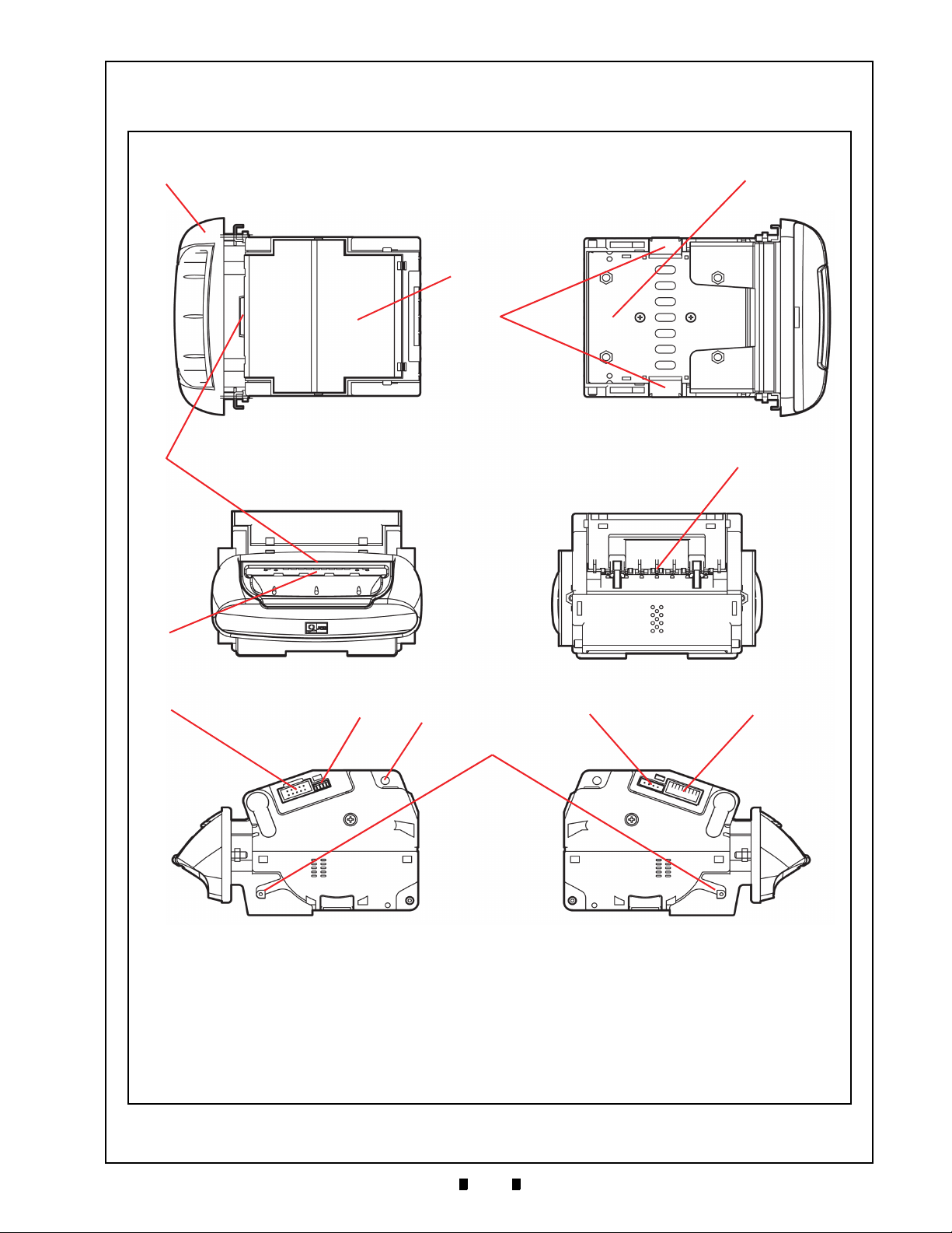
Figure 1-11 Taiko PUB-7/11 Component Names
a) Bezel
b) Upper Guide Lid
c) Lower Guide Lid
d) Lower Guide Locking Button
e) LED Display Lens
f) Banknote Insertion Slot
g) Banknote Exit Slot
h) Interface Connector
i) Maintenance Connector
j) Upper Lid Open/Close Button
k) Optional Interface Connector
l) DIP Switch Block
m)Bezel Installation Guide Pin
e
k
f
g
l
c
j
a
b
hi
d
m
Front Rear
Top Bottom
Right Left
Component Names
Figure 1-11 illustrates the Taiko™ PUB-7/11 Component Names and Locations.
P/N 960-100175R_Rev. 4 {EDP #200824} © 2013, Japan CashMachine Co., Limited
Page 18

1-6
Section 1 Taiko™ Series Banknote Acceptor General Information
Specifications
T
ECHNICAL SPECIFICATIONS
Hydrothermal Condition Table
Humidity [%RH]
Temperature [ºC]
Allowable
and Humidity Range
Operating
Temperature
35ºC/85%
50ºC/40%
Table 1-2 Taiko PUB-7/11 Technical Specification
†
Acceptance Rate*:
Banknote Types Accepted:
95% or greater
Note: The following banknote types are excluded:
a) Banknotes with excess or poor magnetism or unclear graphics
b) Double (dual) Notes
c) Worn, dirty, wet, stained, torn or excessively wrinkled Banknotes
d) Banknotes having folded corners or edges
e) Banknotes having the wrong cut dimensions or printing displacement
f) Returned Banknotes because of incorrect or failed insertion.
Long side: 120~160mm (4.72~6.3 in.)
Short side: 62~82mm (2.44~3.23 in.)
Standard Specification
a) Read code interleaved: 2 of 5
b) Narrow Bar: 0.5mm-0.6mm (0.019-0.023 in.)
Barcode Coupon‡:
Insertion Direction:
c) Wide Bar to Narrow Bar ratio = 3:1
d) Characters: 18 Characters
e) Print Position: Middle (Divide a Coupon equally on the left, right, top and
bottom of the Coupon’s center)
f) Print Width: Wider than 10mm (0.39 in.)
Banknote: Four-way
Barcord Coupon: Two way (Barcode Surface Up)
Approximately 2 seconds (from Banknote insertion to denomination signal
Processing Speed**:
output)
Approximately 3 seconds (from Banknote insertion to credit signal output)
Validation Method:
Diagnostic Indicators††:
PUB 7 = Optical (4 wavelength), Transmissive and Reflection
PUB 11 = Optical (4 wavelength), Magnetic, Transmissive and Reflection
Front Panel Bezel LED, Full color illuminating (Gradation & Solid)
Escrow: 1 note
Anti-stringing Mechanism: Pull-Back (PB) Unit (Anti-pullback system - JCM Patented)
**
Interface:
X4: ID-003 (Serial)/MDB/Pulse/ccTalk
01: Parallel (ID-001)
03: Serial (ID-003)
*. When security measures against counterfeiting are implemented, the software may not fulfill the specified acceptance rate level.
†. Refer to the Software Information Sheet related to the specific Country's software.
‡. Refer to the Barcode Coupon Specification.
**.Excluded Host communication time lag. (Power Supply: +12V DC, Temperature: 25ºC ±5ºC)
††.DIP Switch selectable.
E
NVIRONMENTAL SPECIFICATIONS
Table 1-3 Taiko PUB-7/11 Environmental Specification
Operating Temperature: +5ºC to +50ºC (41ºF to 122ºF)
Storage Temperature: -20ºC to +60ºC (-4ºF to 140ºF)
Relative Operating Humidity: +20% to 85% RH (non-condensed)
Relative Storage Humidity: +20% to 85% RH (non-condensed)
Visible Light Sensitivity:
Installation: Indoors Only
P/N 960-100175R_Rev. 4 {EDP #200824} © 2013, Japan CashMachine Co., Limited
Avoid contact with direct sunlight (Interior lighting must be incandescent with a
Radiant Angle of 15 Degree or more having an Illumination index of 3000 Lux or less)
Page 19
1-7
General Information Taiko™ Series Banknote Acceptor Section 1
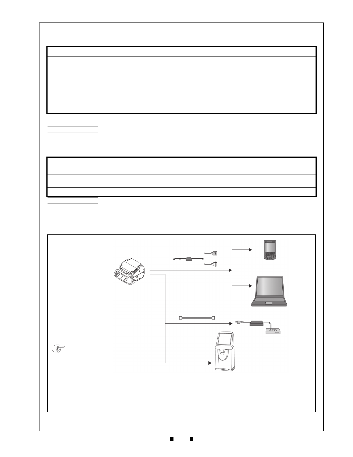
Figure 1-12 Taiko PUB-7/11 System Configuration
a
b
c
d
g
f
e
Maintenance Connector
Interface
Connector
Communications
NOTE: The Communications Harness
needs to be prepared by the Customer.
Harness
a) Taiko™ PUB-7/11 Unit
b) Palm Pilot Tungsten C
c) PC (Windows 98SE/2000/XP)
d) JCM Power Supply Unit (EDP# 116125, JAC Part# 501-000187RA)
e) Taiko™ Harness B (EDP# 116488, JAC Part# 400-100573RA)
f) Taiko™ Harness A (EDP# 121797, JAC Part# 400-100551RA)
g) Host Machine (Gaming, Vending, etc.)
E
LECTRICAL SPECIFICATIONS
Table 1-4 Taiko PUB-7/11 Electrical Specification
Supply Voltage*:
12V DC ±5%/24V DC ±10%
†
Standard Specification
Standby = 0.1A [12V DC]/0.1A [24V DC]
Operation = 0.5A [12V DC]/0.5A [24V DC]
Maximum = Approximately 1.4A (Maximum of 300ms) [12V DC]/
Current Consumption‡:
Approximately 1.0A (Maximum of 300ms) [24V DC]
Barcode Specification
Standby = 0.1A [12V DC]
Operation = 0.6A [12V DC]
Maximum = Approximately 1.6A (Maximum of 300ms) [12V DC]
*. 12V DC = 7-Pin, 24V DC = 9-Pin.
†. 24V DC is available only when the optional 24V DC Specification is used.
‡. Use the CLASS2 Limited Power Source.
**.Motor Initializing or Motor Lock Up current consumption.
S
TRUCTURAL SPECIFICATIONS
**
Table 1-5 Taiko PUB-7/11 Structural Specification
Weight: Approximately 0.6kg (1.3 lbs)
Mounting*:
Outside Dimensions:
Cash Box:
*. Allow 3.93 inches (100mm) above the Unit for opening the Lid and Bezel removal.
†. Cash Box must be 3.93 inches (100mm) or more in depth from the bottom of the TAIKO Unit, 7.87 inches (200mm) or more in depth from the Unit rear
and 3.93 inches (100mm) or more in width.
Horizontal (on door - non vibrating)
See “Taiko PUB-7 Standard Bezel Unit Outside Dimensions” on page 1-8
of this Manual.
User prepared
†
System Configuration
Figure 1-12 illustrates a typical Taiko™ PUB-7/11 system configuration.
P/N 960-100175R_Rev. 4 {EDP #200824} © 2013, Japan CashMachine Co., Limited
Page 20
1-8
Section 1 Taiko™ Series Banknote Acceptor General Information
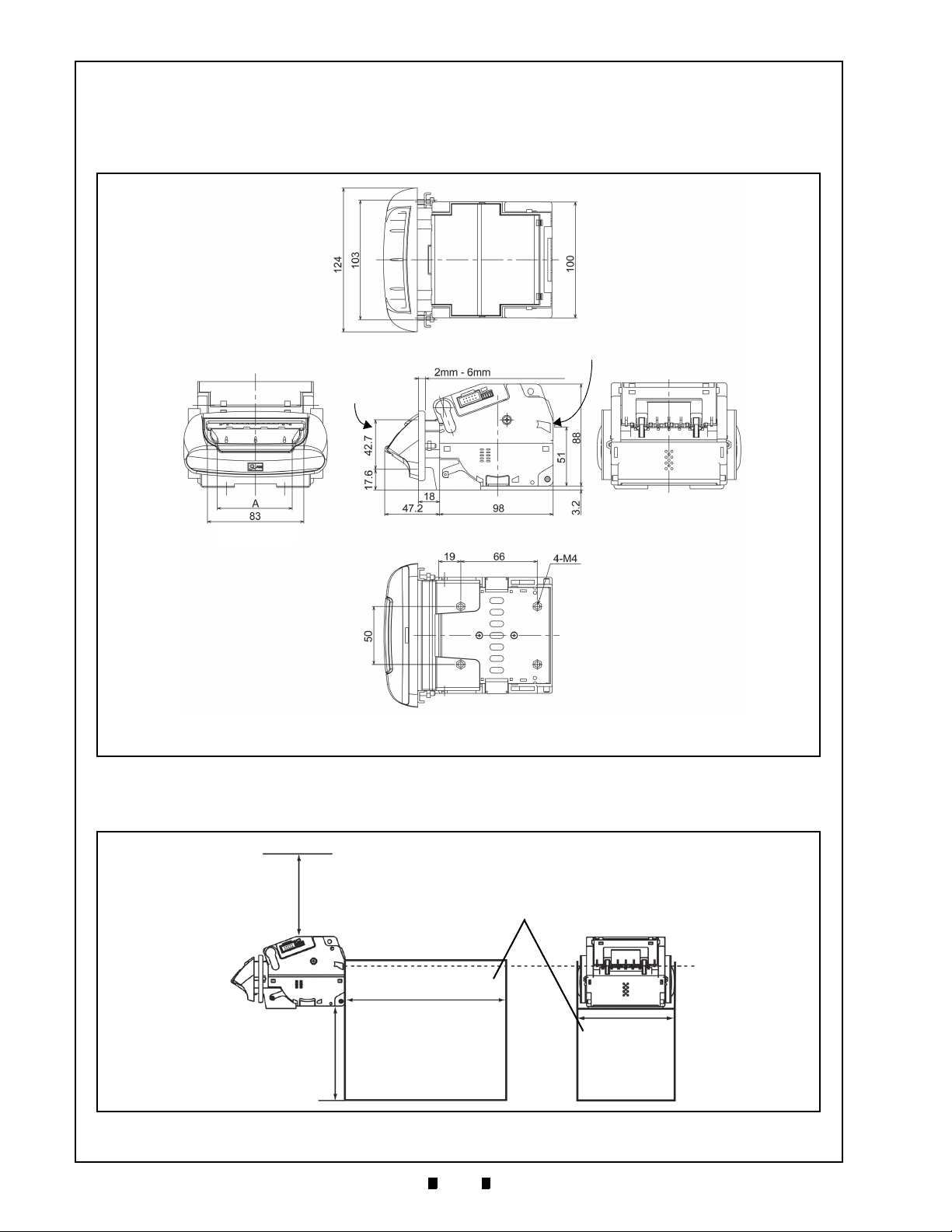
NOTE: All Dimension are in Millimeters
Door Installation
Position
(Panel Thickness)
51 (Banknote
Ejection Position)
A = 68 (Type 1: Minimum Width @ 67mm)
76 (Type 2: Minimum Width @ 75mm)
71 (Type 3: Minimum Width @ 70mm)
(Maximum Banknote Width 82)
Right Side
Rear Side
Front Side
Top Side
Bottom Side
Figure 1-13 Taiko PUB-7 Complete Unit Outside Dimensions
Overhead Space
3.93 inches
(100mm) or more
Depth Behind Unit
7.87 inches
(200mm) or more
Width
3.93 inches
(100mm)
or more
Depth Below Unit
3.93 inches
(100mm) or more
Banknote Ejection
Slot Position
Cash Box
Figure 1-14 Taiko PUB-7/11 Banknote Acceptor’s Clearance Dimensions
Unit Dimensions
T
AIKO
PUB-7 S
Figure 1-13 illustrates the Taiko™ PUB-7 Type 1, Type 2 or Type 3 Standard Bezel Unit outside dimensions.
TANDARD BEZEL UNIT OUTSIDE DIMENSIONS
Taiko PUB-7/11 Unit Clearance Dimensions
Figure 1-14 illustrates the Taiko™ PUB-7/11 Unit’s open Acceptor clearance dimensions.
P/N 960-100175R_Rev. 4 {EDP #200824} © 2013, Japan CashMachine Co., Limited
Page 21
1-9
General Information Taiko™ Series Banknote Acceptor Section 1
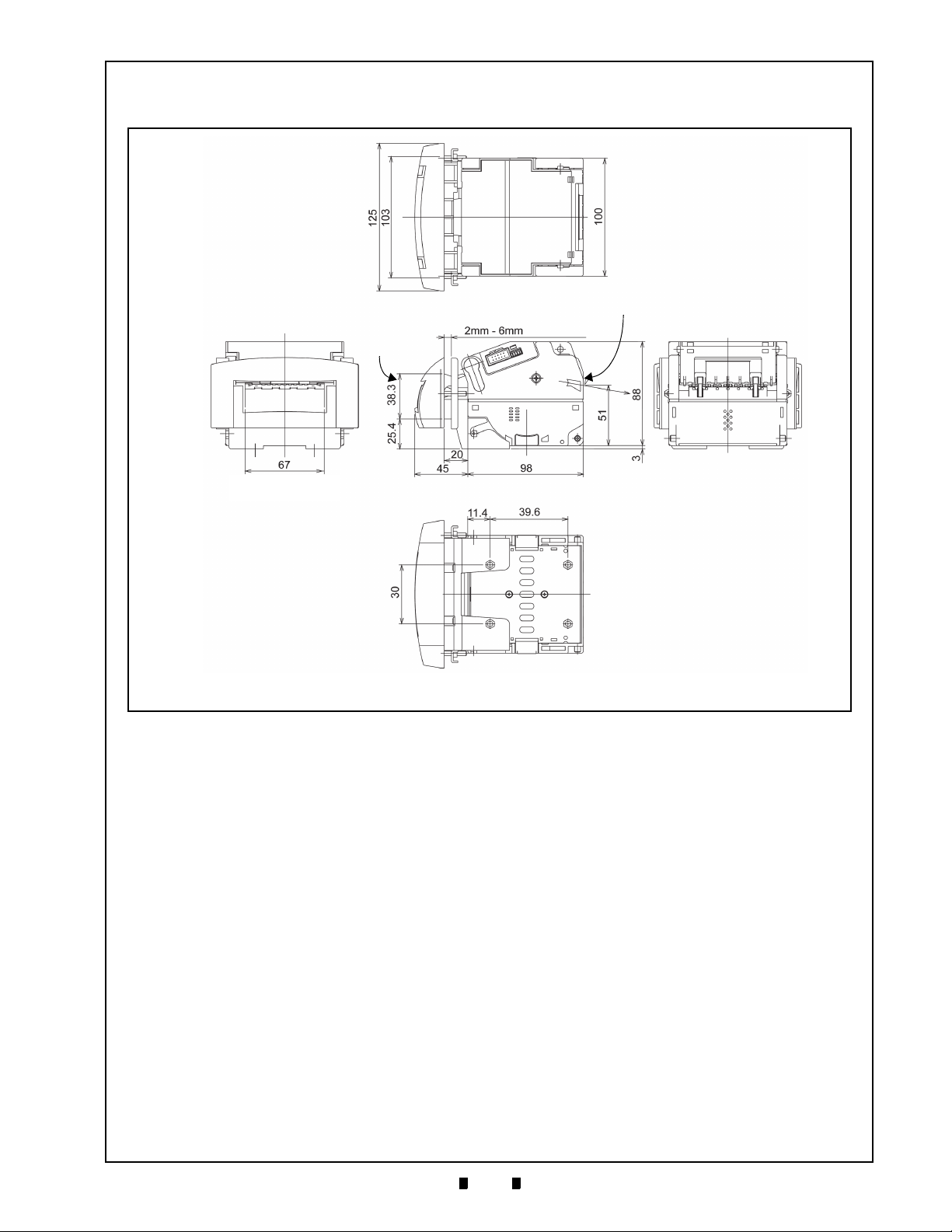
NOTE: All Dimension are in Millimeters
Door Installation
Position
(Panel Thickness)
51 (Banknote
Ejection Position)
A = 68 (Type 1: Minimum Width @ 67mm)
76 (Type 2: Minimum Width @ 75mm)
71 (Type 3: Minimum Width @ 70mm)
(Maximum Banknote Width 66)
Right Side
Rear Side
Front Side
Top Side
Bottom Side
Figure 1-15 Taiko PUB-11 (US Dollar) Complete Unit Outside Dimensions
T
AIKO
PUB-11 S
TANDARD
US B
EZEL UNIT OUTSIDE DIMENSIONS
Figure 1-15 illustrates the Taiko™ PUB-11 Type 5 Standard US Bezel Unit outside dimensions.
P/N 960-100175R_Rev. 4 {EDP #200824} © 2013, Japan CashMachine Co., Limited
Page 22
1-10
Section 1 Taiko™ Series Banknote Acceptor General Information
or
or or
or
E142330, Subscriber 857947001, Vol. 2
International Compliance
• RoHS Directives
• UL & c-UL Marks
• CE Mark .
P/N 960-100175R_Rev. 4 {EDP #200824} © 2013, Japan CashMachine Co., Limited
Page 23

1-11
General Information Taiko™ Series Banknote Acceptor Section 1
To obtain further Technical Information regarding the Taiko™ PUB-7/11 Device, please contact the closest office to your location listed below:
Technical Contact Information
A
SIA
& O
A
MERICAS
JCM American
Phone: +1-702-651-0000
Fax: +1-702-644-5512
925 Pilot Road, Las Vegas, NV 89119
E-mail: support@jcmglobal.com
E
UROPE
, A
FRICA
, R
USSIA
& M
JCM Europe GmbH
Phone: +49-211-530-645-60
Fax: +49-211-530-645-65
Muendelheimer Weg 60
D-40472 Duesseldorf Germany
E-mail: support@jcmglobal.eu
UK & I
RELAND
JCM Europe (UK Office)
Phone: +44 (0) 190-837-7331
Fax: +44 (0) 190-837-7834
JCM Gold (HK) Ltd.
IDDLE EAST
Japan Cash Machine Co, Limited (HQ)
CEANIA
Phone: +852-2429-7187
Fax: +852-2929-7003
Unit 1-7, 3/F., Favor Industrial Centre
2-6 Kin Hong Street, Kwai Chung,
N.T. Hong Kong
E-mail: asiapactechsupport@jcmglobal.com
Phone: +81-6-6703-8400
Fax: +81-6-6707-0348
2-3-15, Nishiwaki, Hirano-ku, Osaka 547-0035
JAPAN
E-mail: Shohin@jcm-hq.co.jp
All of these Websites are available via:
http://www.jcmglobal.com
Unit B, Third Avenue
Denbigh West Business Park
Bletchley, Milton Keynes,
Buckinghamshire MK1 1DH, UK
E-mail: support@jcmglobal.eu
P/N 960-100175R_Rev. 4 {EDP #200824} © 2013, Japan CashMachine Co., Limited
Page 24

1-12
Section 1 Taiko™ Series Banknote Acceptor General Information
THIS PAGE INTENTIONALLY LEFT BLANK
P/N 960-100175R_Rev. 4 {EDP #200824} © 2013, Japan CashMachine Co., Limited
Page 25
2-1
Taiko™ Series
2 INSTALLATION
WARNING: Turn the equipment power OFF before removing or replacing any
Taiko™ components!
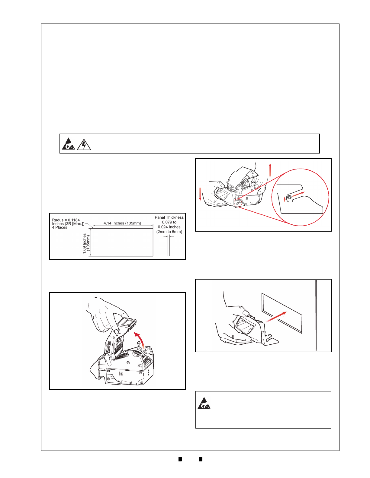
Figure 2-1 Taiko Bezel Cut-Out Dimensions
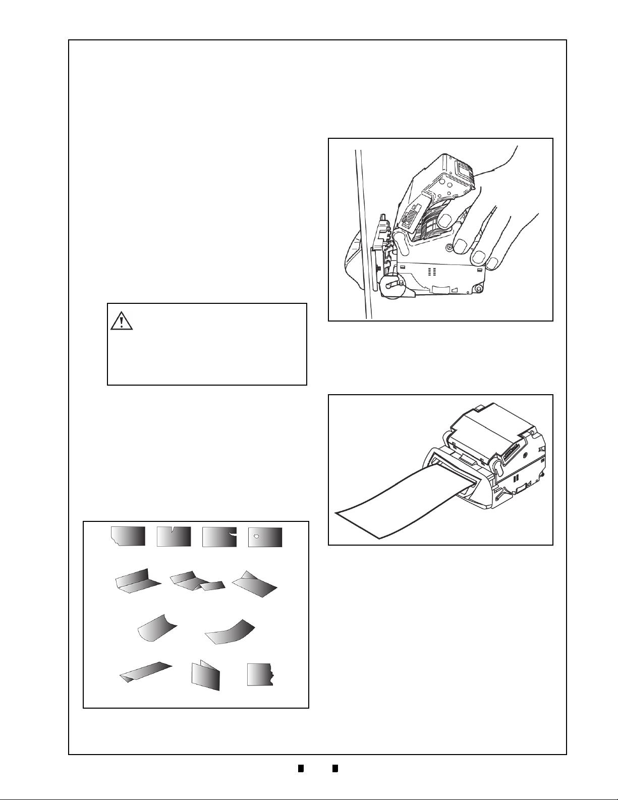
Figure 2-2 Opening Taiko’s Upper Lid
Figure 2-3 Removing the Taiko Bezel
Figure 2-4 Installing the Taiko Bezel
WARNING: Tightening the Nuts with too
much force can damage the Bezel. The
necessary torque is 0.513 foot-lbs
(0.7Nm).
Banknote Acceptor
Section 2
This section provides installation/operation
instructions for the Taiko™ Banknote Acceptor
Series (PUB-7/11). This section contains the
following information:
• Installation and Removal
• DIP Switch Configurations
Installation and Removal
Installing the PUB-7/11 Taiko Bezel
To install or remove a Taiko™ PUB-7/11 Unit
Bezel in a door or wall perform the following steps:
1. Create the correct sized opening required to
install the Taiko™ Bezel, using the Panel Cut-Out
Dimensions shown in
2. Open the Upper Lid in the arrow direction shown
in Figure 2-2 by pressing in on the Upper Lid
Open/Close Buttons.
Figure 2-1.
• Connector Pin Assignments
• Preventive Maintenance
• Clearing Banknote Jam
• Cleaning
• Interface Schematic
• Operational Flowchart..
6. Remove the two (2) Bezel Brackets and the two
(2) Hexagonal Nuts from the Bezel.
7. Insert the Bezel into the previously cut-out
area in the Door Front Panel as shown in
Figure 2-4.
3. Hold the Taiko™ Unit by placing your hand
under the Upper Lid (
4. Slightly press down on the Bezel and raise the
5. Slide the body back and up to detach it from the
P/N 960-100175R_Rev. 4 {EDP #200824} © 2013, Japan CashMachine Co., Limited
rear Taiko™ Unit body (
Bezel section (
See Figure 2-3 ).
See Figure 2-3 ).
See Figure 2-3 ).
8. Set the Bezel in the door hole and attach the two
(2) Bezel Brackets to the back side of the Bezel
using the two (2) Hexagonal Nuts previously
removed (
See Figure 2-5).
Page 26
2-2
Section 2 Taiko™ Series Banknote Acceptor Installation
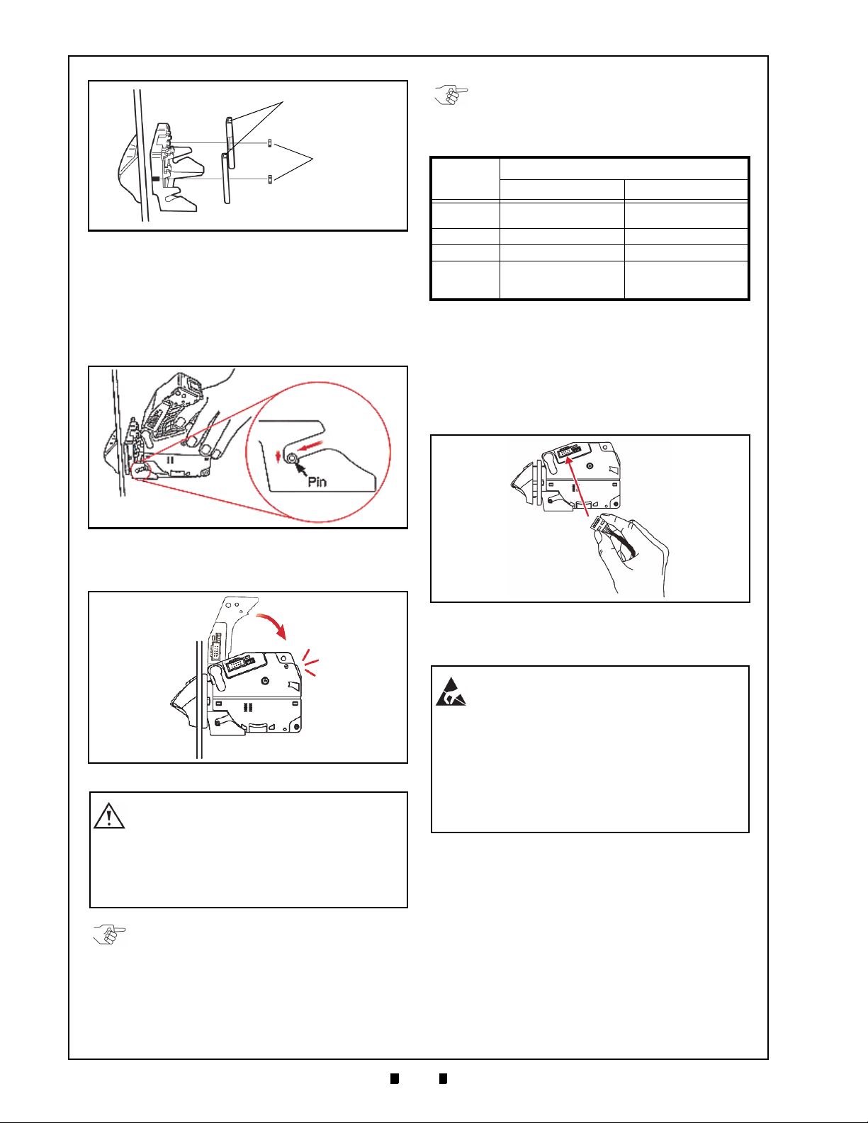
Figure 2-5 Mounting the Taiko Bezel
Bezel Brackets
Hexagonal
Nuts
Figure 2-6 Installing the Taiko Bezel
Figure 2-7 Closing the Taiko Upper Lid
Click
Caution: Ensure that the Taiko Unit body
and Bezel are firmly installed and stably
fixed to the door before closing the
Upper Lid; When closing the Upper Lid,
be careful not to get your finger caught
under the lid when pressing it closed.
NOTE: When removing a Taiko Unit, perform the
reverse procedure as previously described.
NOTE: DIP Switch settings may vary based on
Software changes related to the specific Country
using the Taiko Unit.
Figure 2-8 Attaching a Taiko Power Connector
WARNING: When installing a Taiko Unit,
or connecting its Harness Plug, be sure
power to the harness is disconnected.
The Taiko Unit is only designed to use a
12 Volt DC input. Any other power level
can damage the Taiko Unit!
If the power Harness itself is strongly
pulled on, it may tear loose from its
Connector’s Pins.
Table 2-1 Power Connector Specifications
Connector
XG4M-1030-T
(Omron)
1.27mm Pitch Flat
Ribbon Cable, AWG28
UL2651 or UL20012
9. Open the Upper Lid by pressing-in and holding
down the Upper Lid Open/Close Buttons while
lifting the Lid up (
See Figure 2-6 ).
10. Insert the Bezel Installation Guide Pin into the
Bezel Guide (See Figure 2-6 ).
11. Slide the Guide all the way in and push down on
the Taiko™ Unit body (
See Figure 2-6 ).
Part
Plug
Semi-Cover XG5X-0501 (Omron) N/A
Lock Lever 2 XG4Z-0002 (Omron) N/A
Applicable
Wire Size
Lock Lever Socket Ribbon Cable Socket
XG5M-1032-N
(Omron)
UL1061 WAG24
Once the Power Interface Connector Plug has been
fastened to the Power/Signal Cable being used,
perform the following steps:
1. Confirm the power is NOT supplied to the new
Power Harness.
2. Insert the new Power Harness Socket into the
right side Panel Interface Connector of the
Taiko™ Unit Body (
See Figure 2-8).
12. Close the Upper Lid firmly until a locking Click
is heard (
Power Harness Wiring Procedure
Before beginning to build a Power Interface
Connector, ensure one of the two plug types listed
in
Table 2 -1 are available.
P/N 960-100175R_Rev. 4 {EDP #200824} © 2013, Japan CashMachine Co., Limited
See Figure 2-7).
3. Supply power and confirm that the Taiko™ Unit
operates properly.
Clearing a Banknote Jam
Clearing an Upper Area Banknote Jam
When an upper area Banknote jam occurs, the
Front Panel Red LED Display will begin blinking
three (3) time with a pause between blink sets.
Perform the following steps to clear a Banknote
jam within the Taiko™ Unit’s Acceptor area:
1. Remove Power from the Taiko™ Unit.
Page 27

2-3
Installation Taiko™ Series Banknote Acceptor Section 2
Figure 2-9 Upper Area Banknote Jam Removal
Caution: When closing the Upper Lid,
be careful not to get your finger caught
under the Lid when closing it!
Figure 2-10 Lower Area Banknote Jam Removal
NOTE: Re-install the Taiko Unit onto the Bezel
by reversing the steps related to, and beginning
from Figure 2-6 on page 2-2 of this Section.
Figure 2-11 Left Side DIP Switch Block Location
Left Side
ON
DIP Switch Block
ON
6 7 8 IF Setting
OFF OFF OFF ID-003 Serial
ON OFF OFF MDB
OFF ON OFF ccTalk (Non-Encrypted)
ON ON OFF
ccTalk (Encrypted)
*
*. If the encryption code is unclear, refer to the “Encryption Code Initia lization
Setting Mode” on page 2-5 of this Section to initialize the Encryption Code.
--ON
Pulse
†
†. For detailed i nformation concerning Communication Settings, refer to the
individual Country’s Software Information Sheet.
2. Press-in on the Upper Lid Open/Close Buttons
and open the Upper Lid in the direction indicated
in
Figure 2-9 .
3. Remove the jammed Banknote as illustrated in
Figure 2-9 .
Clearing a Lower Area Banknote Jam
When a lower area Banknote jam occurs, the Front
Panel Red LED Display will begin blinking four (4)
times with a pause between blink sets.
Perform the following steps to clear a Banknote
jam within the Taiko™ Unit’s Transport area:
1. Remove Power from the Taiko™ Unit.
2. Remove the Taiko™ Unit body from the mounted
Bezel Section (review removal instruction shown
in
Figure 2-3 on page 2-1 of this Section).
3. Remove the Lower Lid by pressing-in on the
Lower Lid Lock Release Button (See Figure 2-10
).
4. Remove the jammed Banknote as illustrated in
See Figure 2-10 .
DIP Switch Configurations
The communication method and various Taiko™
Unit functions can be selected by using the Unit’s
Left side set of DIP Switches (
Table 2 -2 lists the various typical DIP Switch settings available for programing the Taiko™ Unit.
Table 2-2 Typical DIP Switch Settings
Switch
No.
1
2
3 Reserved Reserved
4
5
6
Double Scan Mode
Five (5) Drum Rotation
(Anti-Fishing Prevention)
Switch Position Setting
ON OFF
Test Mode 1
‡
Cycles
Refer to the specific Country’s Software
See Figure 2-11).
*
†
Normal Scan Mode
Normal Operation
Specifications
Normal Mode
P/N 960-100175R_Rev. 4 {EDP #200824} © 2013, Japan CashMachine Co., Limited
7
8
*. For details concerning the Test Mode, refer to “Performance Test
Diagnostics” on page 6-7 in Section 6.
†. The acceptance rate will be improved, but operation time will be
increased if a Banknote (note) is rejected.
‡. Anti-Fishing prevention will be improved, but operation time will
increase.
Table 2 -3 lists the various special DIP Switch
settings available for programing the Taiko™ Unit.
Page 28

2-4
Section 2 Taiko™ Series Banknote Acceptor Installation
ON
Figure 2-12 “Accept’ Mode DIP Switch Settings
ON
Figure 2-13 ‘Inhibit’ Mode DIP Switch Settings
ON
NOTE: The Accept/Reject setting for a Banknote
denomination can be confirmed by observing the
Front Panel LED Color. After an initial operation
is performed, the LED will flash a number of
times equal to the total number of Banknote
denominations processed. Blue indicates an
‘Accept’ setting and Red indicates a ‘Reject’
setting.
Figure 2-14 Define Pattern 1 DIP Switch Settings
ON
Figure 2-15 Define Pattern 2 DIP Switch Settings
ON
Table 2-3 Programming DIP Switch Settings
Setting Function SW1 SW2 SW3 SW4 SW5 SW6 SW7 SW8
LED
Pattern 1
Pattern 2
Mode
Accept
Setting
Inhibit
Setting
Define
Define
ON OFF OFF OFF OFF ON OFF OFF
ON OFF OFF OFF OFF ON ON OFF
ON ON OFF OFF OFF OFF ON OFF
ON OFF ON OFF OFF OFF ON OFF
ON ON ON ON ON ON OFF OFF
*
ON OFF OFF OFF OFF OFF ON ON
*
ON ON OFF OFF OFF OFF OFF ON
“Software Downloading Procedure” on page 6-2 in
Denom.
Val ue
Setting
Mode
Pattern
Setting
Mode
Encryption Code
Initialization Setting
Download Mode
Adjustment Mode
*. For details concerning Taiko™ Software Download and Adjustment
Modes, refer to
Section 6 of this Service Manual.
Denomination Setting Mode
Perform the Accept/Inhibit setting function for the
Banknote Denomination required based on the
Software requirements of the Specific Country in
which it is being used. The default settings are to
accept all Denominations of the Specific Country.
A
CCEPT SETTING MODE
To establish an “Accept” setting function, perform
the following steps:
2. Set DIP Switch No.1, No. 6 and No.7 to ON
(
See Figure 2-13).
3. Re-apply Power to the Taiko™ Unit.
4. After the Front Panel LED display flashes White,
set DIP Switch No.1 to the OFF position to enter
the Setting Mode.
5. Insert the Banknote Denomination to be inhibited
into the Insertion Slot. The setting is registered if
the Front Panel LED display remains lit an
Orange Color, and the inserted Banknote is
returned.
6. Insert next Banknote Denomination to be inhibited until all required values have been processed.
The Banknote ‘Accept’ or ‘Inhibit’ programing
operations are now complete.
LED Pattern Setting Mode
The LED Color Pattern Type can be changed
according to user preference. Select between Pat
tern 1 or Pattern 2. The default setting is Pattern 1.
D
EFINING PATTERN
1
To define a “Pattern 1” (a flashing Color Sequence)
operating function, perform the following steps:
1. Remove Power from the Taiko™ Unit.
2. Set DIP Switch No.1, No.2 and No.7 to ON
(
See Figure 2-14).
-
1. Remove power from the Taiko™ Unit.
2. Set DIP Switch No.1 and No.5 to ON (See Figure
2-12 above).
3. Re-apply Power to the Taiko™ Unit.
4. After the Front Panel LED display flashes White,
set DIP Switch No.1 to the
OFF position to enter
the Setting Mode.
5. Insert the Banknote Denomination to be accepted
into the Insertion Slot. The setting registered is
correct if the Front Panel LED Display remains lit
a light Blue Color, and the inserted Banknote is
returned.
6. Insert the next Banknote Denomination to be
accepted until all required values have been
processed, set and accepted.
I
NHIBIT SETTING MODE
To establish an “Inhibit” setting function, perform
the following steps:
1. Remove Power from the Taiko™ Unit.
P/N 960-100175R_Rev. 4 {EDP #200824} © 2013, Japan CashMachine Co., Limited
3. Re-apply Power to the Taiko™ Unit.
4. Set DIP Switch No.1 to OFF to cause the LED
Display Pattern to emulate “Pattern 1” when
operating.
D
EFINING PATTERN
2
To define a “Pattern 2” (a fading Color Sequence)
operating function, perform the following steps:
1. Remove Power from the Taiko™ Unit.
2. Set DIP Switch No.1, No.3 and No.7 to ON
(
See Figure 2-15).
3. Re-apply power to the Taiko™ Unit.
4. Set DIP Switch No.1 to OFF to cause the LED
Display Pattern to emulate “Pattern 2” when
operating.
Page 29

2-5
Installation Taiko™ Series Banknote Acceptor Section 2
Figure 2-16 Encryption Mode DIP Switch Settings
ON
Figure 2-17 ID-003/MDB/Pulse Interface
Connector
Internal 10-Pin S10B-PADSS-1 (JST)
Figure 2-18 ID-001 Interface Connector
Internal 16-Pin S16B-PADSS-1 (JST)
Encryption Code Initialization Setting Mode
When using the ccTalk Communication Mode (e.g.,
The Encryption Mode) and the Encryption Code is
unknown, set the Encryption Code Initialization
Setting to start the Encryption Code in order to
identify the last 6 Digits of the specific Taiko™
Serial Number located on the back side of a
Taiko™ Unit.
To set the “Encryption Mode” operating function,
perform the following steps:
1. Remove Power from the Taiko™ Unit.
2. Set DIP Switch No.1 through No.6 to ON, and
Switches No.7 and No.8 to
OFF (See Figure 2-
16).
3. Re-apply Power to the Taiko™ Unit.
4. Set DIP Switch No.1 to OFF to initialize the
Encryption Code setting.
The Taiko™ installation DIP Switch settings are
now complete.
Error Codes & Conditions
Table 2 -4 lists the Red Error Code flash sequence
definitions displayed by the Taiko™ Front Panel
LED indicator.
Table 2-4 Red LED Error Code Flash Definitions
Red
Flashes
2
ROM Error
3 Banknote Jam inside Ejection Slot
4 Banknote remains inside on the Transport Path
5 EEPROM Read/Write Error
6 Motor Error
8 Entrance Solenoid Error
9 Exit Solenoid Error
12 Sensor Operation with Abnormal Timing
Interface Connector Pin
Error Indicated
Assignments
Table 2 -5, Table 2-6, Table 2-7 and Table 2-8 list
the various Connector Pin Labels for adapting these
available Communication Standards to the Unit.
Table 2-5 Serial ID-003/MDB Interface Pin
Assignments
Pin No.
*. I/O (Input/Output) is the function viewed from the Banknote Acceptor
Side.
†. 24V DC is available only when the optional 24V DC Specification is
used.
Signal
Name
1 NC - No Connection
2 NC - No Connection
3 RXD-
4 RXD+
5 TXD-
6 TXD+
7 Vcc - +12V DC Power (7-Pin)
8 Vss - Power Ground
9 Vcc -
10 NC - No Connection
*
I/O
Data Receive Line
IN
(Active when current is present)
Data Send Line
OUT
(Active when current is present)
+24V DC Power (9-Pin)
Function
†
Table 2-6 ccTalk Interface Pin Assignments
Pin No.
*. I/O (Input/Output) is the function viewed from the Banknote Acceptor
Side.
†. 24V DC is available only when the optional 24V DC Specification is
used.
Signal
Name
1 ccTalk IN/OUT ccTalk Send/Receive Line
2 ccTalk - ccTalk GND Line
3 NC - No Connection
4 NC - No Connection
5 NC - No Connection
6 NC - No Connection
7 Vcc - +12V DC Power (7-Pin)
8 Vss - Power Ground
9 Vcc -
10 NC - No Connection
*
I/O
+24V DC Power (9-Pin)
Function
†
Table 2-7 Pulse Interface Pin Assignments
Pin No.
*. I/O (Input/Output) is the function viewed from the Banknote Acceptor
Side.
†. 24V DC is available only when the optional 24V DC Specification is
used.
Signal
Name
1
2 NC - No Connection
3
4
5 Vend (-)
6 Vend (+)
7 Vcc - +12V DC Power (7-Pin)
8 Vss - Power Ground
9 Vcc -
10 NC - No Connection
NC
Enable/
Disable (-)
Enable/
Disable (+)
*
I/O
-
No Connection
Enable/Disable Signal Input Line
IN
(Enabled when current is present)
(Disabled when current is present)
No Connection
Pulse Signal Output Line
OUT
(Active when current is present)
+24V DC Power (9-Pin)
Function
†
P/N 960-100175R_Rev. 4 {EDP #200824} © 2013, Japan CashMachine Co., Limited
Page 30

2-6
Section 2 Taiko™ Series Banknote Acceptor Installation
Caution: Do not use Alcohol, thinner or
citrus based products for cleaning any
surfaces. The Lenses can become
clouded by chemical effect that may
cause acceptance errors.
Figure 2-19 Sensor Cleaning
Lens
Roller
Lint-free Cloth Cotton Swab Air
Before
Cleaning
After
Cleaning
Belt
Figure 2-20 JCM Waffletechnology Cleaning Card
New Cleaning Card
Cleaning Card Pouch
Table 2-8 Parallel ID-001 Interface Pin
Assignments
Pin No.
*. I/O (Input/Output) is the function viewed from the Banknote Acceptor
Side.
Signal
Name
1 Vcc - +12V DC Power
2 Vss - +12V DC Power Ground
3 Vss - Power Supply Ground
4 NC - No Connection
5 ACK
6 REJ REJect Signal Receive Line
7 INH INHibit Signal Receive Line
8 VAL ID
9 VEND1 VEND1 Valid Send Signal Line
10 VEND2 VEND2 Valid Send Signal Line
11 VEND3 VEND3 Valid Send Signal Line
12 NC - No Connection
13 NC - No Connection
14 BUSY
15 ABN ABortNote Signal Line
16 STKF STacKerFull Signal Line
*
I/O
ACKnowledge Signal Receive Line
IN
Vend VALID Send Signal Line
OUT
BUSY Signal Send Line
OUT
Function
Cleaning Procedures
To clean the Taiko™ Unit, gently rub the Sensors
and Rollers clean using a dry, soft, lint-free cloth
ONLY.
Do not use any Alcohol, solvents, Citrus based
products or scouring agents that may cause damage
to the Validation Section Sensors and/or Rollers.
Sensor and Roller Cleaning Procedure
To clean the Taiko™ Unit, proceed as follows:
1. Turn the Taiko™ Unit and Host Machine’s Power
Supply’s OFF.
2. Open the Taiko™ Upper Guide Lid.
3. Clean the appropriate path and Lens of each
Sensor (See Figure 2-21 areas “a” through “k”
and the corresponding descriptions listed in Table
2-9 to locate each Sensor that require cleaning).
Available Cleaning Card
A JCM Waffletechnology Bill Validator Cleaning
Card is now available (JCM Part No. 501-000252R,
Manufacturer’s Part No. KWJCM-B5B15M). The
Cleaning Card is designed to be used as a supple
mental part of a Preventive Maintenance program
to help in reducing dirt and Paper dust build-up
within a Unit. This will optimize performance
between regular Preventive Maintenance intervals.
This is the only cleaning card authorized for use on
the Taiko (PUB-7/11) Validator (
See Figure 2-20).
Card Features
• A unique Waffletechnology design that hugs all
surfaces to insure complete surface cleaning
• Specially designed scrubber patterns insure
that belts and O-ring Rollers are cleaned and
lubricated to prevent them from drying out.
Directions For Use
1. Remove Cleaning Card from pouch and insert it
into the Banknote Validator.
2. The Cleaning Card will be accepted and then
automatically returned.
3. Dispose of used Card in an environmentally safe
manner.
For more information and a list of Authorized
Waffletechnology Distributers visit:
http://www.jcmwaffletechnology.com.
-
P/N 960-100175R_Rev. 4 {EDP #200824} © 2013, Japan CashMachine Co., Limited
Page 31

2-7
Installation Taiko™ Series Banknote Acceptor Section 2
Taiko Sensor and Roller Locations
Figure 2-21 illustrated the various Taiko Sensor cleaning locations, and Table 2-9 respectively lists the
Taiko Sensor Type Cleaning Methods.
Figure 2-21 Taiko Sensor Cleaning Locations
Dummy Head
b
c
d
g
d
e
b
f
e
j
h
a
a
i
Magnetic
Head Roller
k
g
Table 2-9 Taiko Sensor Type Cleaning Methods
Sym. Sensor Type Cleaning Method
a
b Validation Sensor
c Entrance Flapper Sensor
d Entrance Sensor
e Side Sensor Prism
f Upper Transport Sensor
g Entrance Sensor Prism
h Bend Lever Sensor
i Upper Transport Sensor Prism
j Lower Transport Sensor
k Lower Transport Sensor Prism
*. Wipe and clean all of the Rollers and Green Belts shown in Figure 2-21 using a soft lint-free Cloth.
Side Sensor
Operational Check
Once the Taiko™ Unit is installed, perform the
following steps to ensure the Taiko™ Unit is in its
normal Operational Mode:
Wipe clean using a lint free cloth or blow clean using
Compressed Air.
1. Remove Power and perform Test No.5 “Acceptance Test Procedure” on page 6-9 of Section 6 in
this Service Manual.
2. Return the DIP Switches to their pre-Test Operational Mode positions, and re-apply Power to the
Taiko™ Unit.
*
P/N 960-100175R_Rev. 4 {EDP #200824} © 2013, Japan CashMachine Co., Limited
Page 32

2-8
Section 2 Taiko™ Series Banknote Acceptor Installation
THIS PAGE INTENTIONALLY LEFT BLANK
P/N 960-100175R_Rev. 4 {EDP #200824} © 2013, Japan CashMachine Co., Limited
Page 33

2-9
CONTROLLER SIDE
PUB-7/11 SIDE
*1 Connector Input Pin depends on service voltage.
(12V DC = 7-Pin, 24V DC = 9-Pin)
24V DC is available only when the optional 24V DC
Specification is used.
Figure 2-22 Serial ID-003/MDB Communications Interface Schematic Diagram
Standard Interface Circuit Schematics
Figure 2-22 illustrates the Taiko™ Serial ID-003/MDB Communications Interface Schematic Diagram
Installation Taiko™ Series Banknote Acceptor Section 2
P/N 960-100175R_Rev. 4 {EDP #200824} © 2013, Japan CashMachine Co., Limited
Page 34

2-10
CONTROLLER SIDE
PUB-7/11 SIDE
*1 Connector Input Pin depends on service voltage.
(12V DC = 7-Pin, 24V DC = 9-Pin)
24V DC is available only when the optional 24V DC
Specification is used.
Figure 2-23 ccTalk Communications Interface Schematic Diagram
Section 2 Taiko™ Series Banknote Acceptor Installation
Standard Interface Circuit Schematics (Continued 1)
Figure 2-23 illustrates the Taiko™ ccTalk Communications Interface Schematic Diagram
P/N 960-100175R_Rev. 4 {EDP #200824} © 2013, Japan CashMachine Co., Limited
Page 35

2-11
CONTROLLER SIDE
PUB-7/11 SIDE
*1 Connector Input Pin depends on service voltage.
(12V DC = 7-Pin, 24V DC = 9-Pin)
24V DC is available only when the optional 24V DC
Specification is used.
Figure 2-24 Pulse Communications Interface Schematic Diagram
Standard Interface Circuit Schematics (Continued 2)
Figure 2-24 illustrates the Taiko™ Pulse Communications LED Schematic Diagram.
Installation Taiko™ Series Banknote Acceptor Section 2
P/N 960-100175R_Rev. 4 {EDP #200824} © 2013, Japan CashMachine Co., Limited
Page 36

2-12
CONTROLLER SIDE
PUB-7/11 SIDE
Figure 2-25 Parallel ID-001 Communications Interface Schematic Diagram
Section 2 Taiko™ Series Banknote Acceptor Installation
Standard Interface Circuit Schematics (Continued 3)
Figure 2-25 illustrates the Taiko™ Parallel ID-001 Communications Interface Schematic Diagram.
P/N 960-100175R_Rev. 4 {EDP #200824} © 2013, Japan CashMachine Co., Limited
Page 37

2-13
CONTROLLER SIDE
PUB-7/11 SIDE
Figure 2-26 Parallel ID-062 Communications Interface Schematic Diagram
Standard Interface Circuit Schematics (Continued 4)
Figure 2-26 illustrates the Taiko Parallel ID-062 Communications Interface Schematic Diagram.
Installation Taiko™ Series Banknote Acceptor Section 2
P/N 960-100175R_Rev. 4 {EDP #200824} © 2013, Japan CashMachine Co., Limited
Page 38

2-14
Taiko™ Series Banknote Acceptor
THIS PAGE INTENTIONALLY LEFT BLANK
P/N 960-100175R_Rev. 4 {EDP #200824} © 2013, Japan CashMachine Co., Limited
Page 39

2-15
Installation Taiko™ Series Banknote Acceptor Section 2
a) Initializing
b) Stand-by
c) Is the Banknote accepted?
e) External LED lights
f) Is the Banknote inserted?
g) Transport the Banknote (Scanning
Banknote Data)
h) Stop Feeding
i) Is the Banknote authentic?
j) Is the Banknote accepted?
A) To “Part 2” Figure 2-28
k) Has the Denomination Signal sent?
B) Return from Figure 2-28
Apply Power to the Unit.
d) External LED distinguish
A) To “Part 3” Figure 2-29
Figure 2-27 Taiko Operational Flowchart (Part 1)
Operational Flowcharts
Figure 2-27 depicts part one of a typical Taiko™ Initialization Banknote acceptance flow process.
P/N 960-100175R_Rev. 4 {EDP #200824} © 2013, Japan CashMachine Co., Limited
Page 40

2-16
Section 2 Taiko™ Series Banknote Acceptor Installation
a) Transport the Banknote out
(Carry the Banknote to the Cash Box)
b) Has the Banknote transported?
c) Retried carrying the Banknote out
d) Has the Banknote transported?
B) To “Part 1” (See Figure 2-27)
g) Stop Operation
A) From “Part 1” (See Figure 2-27)
e) Output the VEND Signal
f) Proceed Completed
h) The Red LED flashes
Figure 2-28 Taiko Operational Flowchart (Part 2)
Figure 2-29 Taiko Operational Flowchart (Part 3)
a) Reject the Banknote
b) Has the Banknote rejected?
c) Retried rejecting the Banknote
d) Has the Banknote rejected
B) To “Part 1” (See Figure 2-27)
g) Stop Operation
A) From “Part 2” (See Figure 2-27)
h) The Red LED flashes
Operational Flowcharts (Continued)
Figure 2-28 depicts part two of a typical Taiko™ Banknote acceptance flow process.
Figure 2-29 depicts part three of a typical Taiko™ Banknote acceptance flow process.
P/N 960-100175R_Rev. 4 {EDP #200824} © 2013, Japan CashMachine Co., Limited
Page 41

3-1
Taiko™ Series
Banknote Acceptor
Section 3
3 COMMUNICATIONS
This section was intentionally left out due to a Non-Disclosure Agreement requirement.
If this information is required, please contact the closest office location listed below:
Americas
JCM A
MERICAN
Phone: +1-702-651-0000
Fax: +1-702-644-5512
925 Pilot Road, Las Vegas, NV 89119
E-mail: support@jcmglobal.com
Europe, Africa, Russia & Middle East
JCM E
UROPE GMB
Phone: +49-211-530-645-60
Fax: +49-211-530-645-65
Muendelheimer Weg 60
D-40472 Duesseldorf Germany
E-mail: support@jcmglobal.eu
H
UK & Ireland
JCM E
UROPE
(UK O
Phone: +44 (0) 190-837-7331
Fax: +44 (0) 190-837-7834
Unit B, Third Avenue
Denbigh West Business Park
FFICE
)
Asia & Oceania
JCM G
OLD
(HK) LTD.
Phone: +852-2429-7187
Fax: +852-2929-7003
Unit 1-7, 3/F., Favor Industrial Centre
2-6 Kin Hong Street, Kwai Chung,
N.T. Hong Kong
E-mail: asiapactechsupport@jcmglobal.com
Japan Cash Machine Co, Limited (HQ)
Phone: +81-6-6703-8400
Fax: +81-6-6707-0348
2-3-15, Nishiwaki, Hirano-ku, Osaka 547-0035
JAPAN
E-mail: Shohin@jcm-hq.co.jp
All of these Websites are available via:
http://www.jcmglobal.com
Bletchley, Milton Keynes,
Buckinghamshire MK1 1DH, UK
E-mail: support@jcmglobal.eu
P/N 960-100175R_Rev. 4 {EDP #200824} © 2013, Japan CashMachine Co., Limited
Page 42

3-2
Section 3 Banknote Acceptor Communications
THIS PAGE INTENTIONALLY LEFT BLANK
P/N 960-100175R_Rev. 4 {EDP #200824} © 2013, Japan CashMachine Co., Limited
Page 43

4-1
Taiko™ Series
4 DISASSEMBLY/REASSEMBLY
a
1
a
2
b
c
Figure 4-1 Taiko Bezel Guide Removal
WARNING: Tightening the nuts with too
much force can damage the Bezel. The
necessary torque is 0.513 foot-lbs (0.7Nm).
a
b
Figure 4-2 Taiko CPU Board Cover Removal
c
a
1
a
2
a
3
a
4
b
1
b
2
b
1
b
2
d
Figure 4-3 Taiko CPU Circuit Board Removal
Banknote Acceptor
Section 4
This section provides disassembly and reassembly
instructions for the Taiko
Acceptor Series. This section contains the follow
ing information:
™ PUB-7/11 Banknote
-
• Tool Requirements
• Primary Unit Disassembly
• Acceptor Unit Disassembly
• Transport Unit Disassembly
• Cash Box Disassembly.
Tool Requirements
The following tools will be required to perform
disassembly and reassembly:
• #1 & #2 Phillips Screw Driver
• Medium Flatblade Screw Driver
• Set of Jewelers Phillips Screw Driver
• E-Clip (E-Ring) Pliers
• Needle Nose Pliers.
Primary Unit Disassembly
The following instructions are provided to perform
an initial disassembly of the Taiko™ Banknote
Acceptor’s primary components.
Bezel Guide Removal
To remove the Bezel Guide, proceed as follows:
1. Remove the two (2) Bezel Mounting Screws
(
See Figure 4-1 a 1 & a 2) located behind the
Bezel Guide (See Figure 4-1 b).
2. Separate the Bezel Guide from its Front Bezel
Section (
See Figure 4-1 c).
CPU Circuit Board Removal
To remove the CPU Circuit Board, proceed as
follows:
1. Insert a medium size Flatblade Screwdriver into
the gap located on the left or right side area of the
Upper Lid Cover (
gently lift the Cover up and off the Assembly.
2. Unplug the four (4) Harness Connectors from the
CPU Circuit Board (
3. Remove the two (2) Self-tapping Circuit Board
Mounting Screws (
retaining the Board in place.
4. Remove the Harness Connector (See Figure 4-3
c) located under the CPU Circuit Board
(
See Figure 4-3 d) and lift the CPU Circuit Board
up and off the Assembly in the direction indicated by the Large Arrow in
5. Reverse Steps 1 to 4 when replacing the CPU
Circuit Board.
See Figure 4-2 a & b), and
See Figure 4-3 a 1 to a 4).
See Figure 4-3 b 1 & b 2)
Figure 4-3.
3. Insert the new Bezel Guide into the exciting
Bezel and replace and tighten the two (2) mount
ing screws that bind the Bezel to the Bezel Guide.
P/N 960-100175R_Rev. 4 {EDP #200824} © 2013, Japan CashMachine Co., Limited
-
Page 44

4-2
Section 4 Taiko™ Series Banknote Acceptor Disassembly/Reassembly
c
a
1
a
2
b
Figure 4-4 Taiko MAG Circuit Board Disconnect
a
Figure 4-5 Taiko MAG Circuit Board Disconnect
c
a
1
a
2
b
a
1
a
2
Figure 4-6 Taiko Side Mounting Screw Removals
c
c
1
c
2
a
b
1
b
2
Figure 4-7 Upper Lid and Side Covers Removal
MAG Board Removal (PUB-11 Only)
The MAG Circuit Board is mounted in a PUB-11
Unit only below the CPU Circuit Board.
To remove the MAG Circuit Board, proceed as
follows:
1. Remove the Harness Connector and remove the
CPU Circuit Board as previously described dur
ing “CPU Circuit Board Removal” on page 4-1 of
this Section.
2. Remove the two (2) Circuit Board Mounting
Screws (See Figure 4-4 a1 & a2) from the MAG
Circuit Board (See Figure 4-4 b).
3. Remove the MAG Circuit Board’s associated
short interboard Harness Connector (
4-4 c).
See Figure
-
3. Remove the Upper Lid (See Figure 4-7 a) and left
and right Side Covers (See Figure 4-7 b1 & b2)
off of the Assembly.
4. Unplug the two (2) Harness Connectors
(See Figure 4-7 c1 & c2) from both the left and
right sides of the Sensor Circuit Board Assembly.
5. Reverse Steps 1 to 4 when replacing the Sensor
Circuit Board.
4. Remove the MAG Circuit Board from the Assembly (See Figure 4-5 a).
Transport Drum Disassembly
To remove the Transport Drum and/or Feed Roller
Assemblies, proceed as follows:
1. Remove the CPU Circuit Board as previously
described during
on page 4-1 of this Section, and perform the procedure for “MAG Board Removal (PUB-11
Only)” on page 4-2 of this Section first if the Unit
is also a Taiko™ PUB-11.
Sensor Circuit Board Removal
To remove the Sensor Circuit Board, proceed as
follows:
1. Remove the CPU Circuit Board as previously
2. Remove the two (2) Side Panel Mounting Screws
described during “CPU Circuit Board Removal”
on page 4-1 of this Section.
from the both the left and right side of the
Taiko™ Unit (
See Figure 4-6 a1 & a2).
2. Remove the Transport Drum (See Figure 4-8 a)
Unit from the Lower Base Assembly (See Figure
4-8 b).
3. Remove the six (6) Transport Drum End Cover
Mounting Screws (
from the right and left end of the Transport Drum
Unit (
See Figure 4-9 b).
4. Separate the Center Guide (See Figure 4-9 c1 &
c6) from the two ends the direction indicated by
the Large Arrows in
“CPU Circuit Board Removal”
See Figure 4-9 a1 through a6)
Figure 4-9.
P/N 960-100175R_Rev. 4 {EDP #200824} © 2013, Japan CashMachine Co., Limited
Page 45

4-3
Disassembly/Reassembly Taiko™ Series Banknote Acceptor Section 4
a
b
Figure 4-8 Taiko Transport Drum Removal
b
Right End
a
1
a
2
a
3
a
4
a
5
a
6
Left End
b
c
1
c
1
Figure 4-9 Right & Left Transport Drum End
Cover Removal
b
a
1
a
2
c
1
c
2
c
3
c
5
c
4
c
6
Figure 4-10 Dual Feed Roller Assembly Removal
a
b
a
b
c
Figure 4-11 Transport Drum Separation
a
b
c
Figure 4-12 Upper Guide Prism Removal
b
c
a
2
a
1
Figure 4-13 Upper Guide Sensor Board Removal
9. Remove the single (1) Prism Mounting Screw
(See Figure 4-12 a) and remove the Prism
(See Figure 4-12 b) from the Upper Center Guide
Assembly (See Figure 4-12 c).
5. Remove the Feed Roller Assembly (See Figure 410 a1 & a2) from both ends of the Center Drum
Unit Assembly (See Figure 4-10 b).
6. Remove the three (3) Washers (See Figure 4-10
c1 through c6) from each end of the Center Drum
Unit Assembly.
See Figure 4-11 b), and
7. Insert a small Flatblade Screwdriver or equivalent
into the encircled area shown in
8. Twist and pry the upper portion of the Center
Guide Section up (
remove it from the Lower Center Guide Section
(
See Figure 4-11 c).
P/N 960-100175R_Rev. 4 {EDP #200824} © 2013, Japan CashMachine Co., Limited
Figure 4-11a.
10. Remove the two (2) Sensor Circuit Board Mounting Screws (See Figure 4-13 a1 & a2).
11. Slide the loose Sensor Circuit Board (See Figure
4-13 b) out through the side opening slit provided
to remove it from the Upper Center Guide
Assembly (
See Figure 4-13 c).
Encoder Board and Drive Motor Removal
To remove the Transport Drum Encoder Circuit
Board and/or Drive Motor Unit, proceed as
follows:
1. Remove the CPU Circuit Board as previously
described during
on page 4-1 of this Section; preform the procedure for “MAG Board Removal (PUB-11 Only)”
on page 4-2 of this Section, and disassemble the
Transport Drum as described in the Section titled
“Transport Drum Disassembly” on page 4-2 of
this Section. However, Steps 9, 10 and 11 of this
last procedure may be omitted.
“CPU Circuit Board Removal”
Page 46
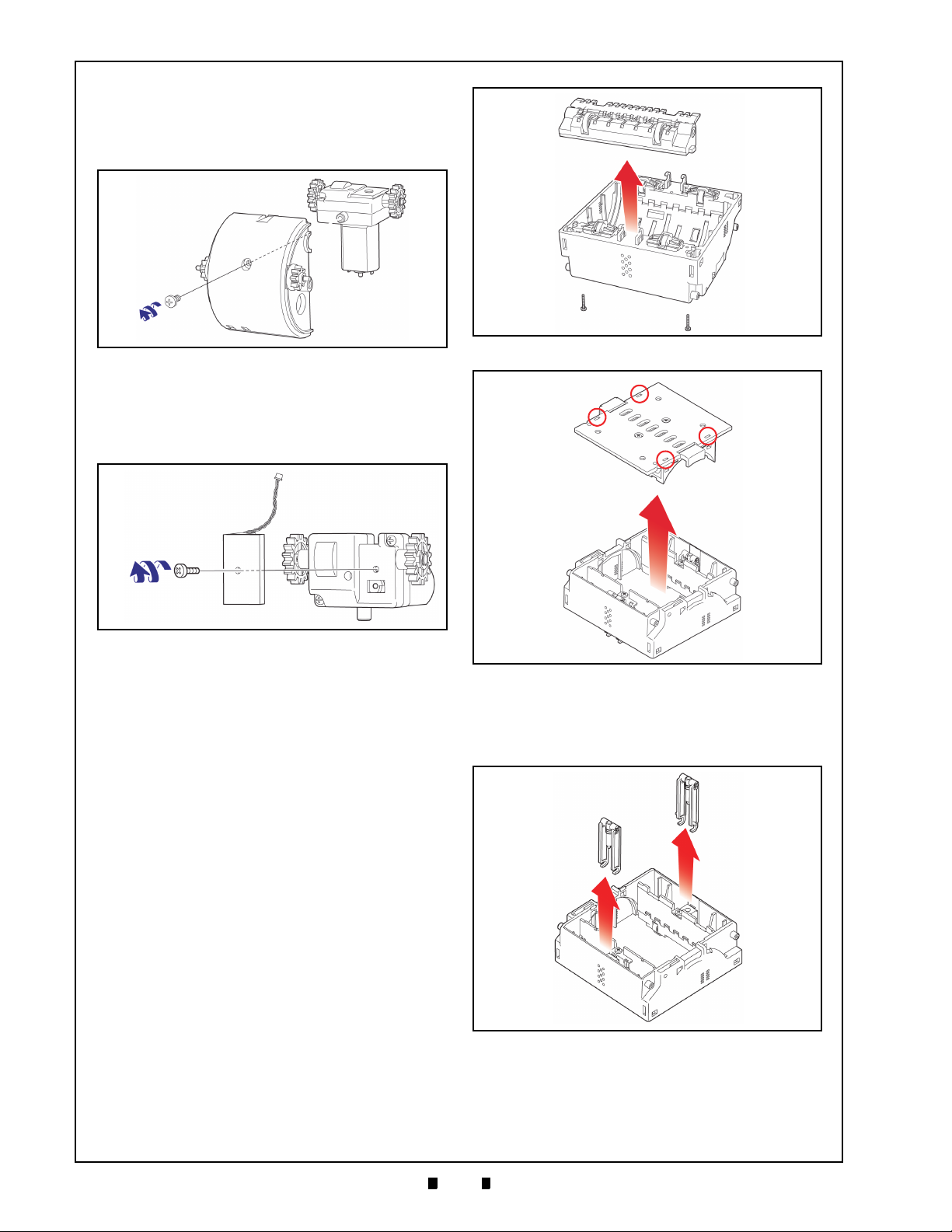
4-4
Section 4 Taiko™ Series Banknote Acceptor Disassembly/Reassembly
a
b
c
Figure 4-14 Motor Drive Assembly Removal
a
b
c
Figure 4-15 Encoder Circuit Board Removal
b
c
a
2
a
1
Figure 4-16 Lower Guide Assembly Removal
b
a
2
a
4
a
1
a
3
Figure 4-17 Lower Guide Assembly Cover
Removal
b
a
2
a
1
Figure 4-18 Lower Guide Lever Removals
2. Remove the single (1) Motor Drive Assembly
mounting screw (
Lower Center Guide (See Figure 4-14 b).
3. Remove the Motor Drive Assembly (See Figure
4-14 c) from the Lower Center Guide Section.
4. Remove the single (1) Encoder Circuit Board
Mounting Screw (
the Encoder Circuit Board (See Figure 4-15 b)
from the Drive Motor Assembly (See Figure 4-15
c).
See Figure 4-14 a) from the
See Figure 4-15 a) and remove
Entrance and Exit Solenoid Removal
To remove the Transport Entrance and Exit Solenoid Unit, proceed as follows:
1. Remove the CPU Circuit Board as previously
described during
on page 4-1 of this Section; preform the procedure for “MAG Board Removal (PUB-11 Only)”
on page 4-2 of this Section, and disassemble the
Transport Drum as described in the Section titled
“Transport Drum Disassembly” on page 4-2 of
this Section. However, Steps 9, 10 and 11 of this
last procedure need not be performed if it is a
PUB-11 Unit.
2. Remove the two (2) Lower Guide Mounting
Screws from the Lower Base Assembly
(
See Figure 4-16 a1 & a2).
3. Remove the Lower Guide Assembly (See Figure
4-16 b).
4. Turn the Lower Base Assembly upside-down and
remove the Lower Lid by pressing in on the four
(4) Lower Lid Open/Close Release Tabs
(
See Figure 4-17 a1 through a4) with a Flatblade
Screwdriver, and pry the lid up and off the
Assembly (
“CPU Circuit Board Removal”
See Figure 4-17 b).
5. Next, remove the two (2) Guide Levers
(See Figure 4-18 a1 & a2) from the Lower Base
Assembly (See Figure 4-18 b).
6. Remove the two (2) Solenoid mounting screws
See Figure 4-19 a1 & a2) and then remove the
(
Entrance and Exit Solenoids (See Figure 4-19 b &
c).
P/N 960-100175R_Rev. 4 {EDP #200824} © 2013, Japan CashMachine Co., Limited
Page 47

4-5
Disassembly/Reassembly Taiko™ Series Banknote Acceptor Section 4
b
a
2
a
1
c
Figure 4-19 Entrance & Exit Solenoid Removal
The Taiko™ Disassembly Procedure is now complete. Reverse all or part of the preceding instructions to reassemble any of the components
described during this disassembly procedure.
P/N 960-100175R_Rev. 4 {EDP #200824} © 2013, Japan CashMachine Co., Limited
Page 48

4-6
Section 4 Taiko™ Series Banknote Acceptor Disassembly/Reassembly
THIS PAGE INTENTIONALLY LEFT BLANK
P/N 960-100175R_Rev. 4 {EDP #200824} © 2013, Japan CashMachine Co., Limited
Page 49

5-1
Taiko™ Series
5 WIRING DIAGRAMS
PUB-7 System Wiring Diagrams
Figure 5-1 PUB-7 12 Volt DC System Wiring Diagram
Banknote Acceptor
Section 5
This Section provides the Taiko™ Banknote Acceptor Series (PUB-7/11) Wiring Diagrams and interconnect information for the following items:
• PUB-7 System Wiring Diagrams
• PUB-11 System Wiring Diagrams.
P/N 960-100175R_Rev. 4 {EDP #200824} © 2013, Japan CashMachine Co., Limited
Page 50

5-2
Section 5 Taiko™ Series Banknote Acceptor Wiring Diagrams
PUB-7 System Wiring Diagrams (Continued)
Figure 5-2 PUB-7 24 Volt DC System Wiring Diagram
P/N 960-100175R_Rev. 4 {EDP #200824} © 2013, Japan CashMachine Co., Limited
Page 51

5-3
Wiring Diagrams Taiko™ Series Banknote Acceptor Section 5
PUB-11 System Wiring Diagrams
Figure 5-3 PUB-11 12 Volt DC System Wiring Diagram (with Mag)
P/N 960-100175R_Rev. 4 {EDP #200824} © 2013, Japan CashMachine Co., Limited
Page 52

5-4
Section 5 Taiko™ Series Banknote Acceptor Wiring Diagrams
PUB-11 System Wiring Diagrams (Continued)
Figure 5-4 PUB-11 24 Volt DC System Wiring Diagram (with Mag)
P/N 960-100175R_Rev. 4 {EDP #200824} © 2013, Japan CashMachine Co., Limited
Page 53

6-1
Taiko™ Series
6 CALIBRATION AND TESTING
NOTE: Refer to the Palm Pilot® or the VM-450
User’s Manual for performing Hot Sync
operations and program installation instructions.
Figure 6-1 Required PUB-7/11 PC Download Workbench Tool
a
To AC Power
To Interface Connector
To Maintenance Connector
10-Pin Interface
Connector
4-Pin Interface
Connector
To PC Serial Port
b
d
e
c
a) Taiko™ (PUB-7/11)
b) JCM VM-30 Power Supply
c) Taiko™ Harness A
d) Taiko™ Harness B
e) PC (OS: Windows
®
98SE/2000/XP)
Figure 6-2 Required PUB-7/11 Palm Pilot Download Workbench Tool
a
To Interface Connector
To Maintenance Connector
10-Pin Interface
Connector
4-Pin Interface
Connector
c
d
b
a) Taiko™ (PUB-7/11)
b) Taiko™ Harness A
c) Taiko™ Harness B
d) Palm Pilot Handheld (
Tungsten
Series C
)
Banknote Acceptor
Section 6
This section provides Flash EPROM Memory
Download Programming using a PC or Palm Pilot
PDA to perform Calibration and Performance Test
ing for the Taiko™ Banknote Acceptor (PUB-7/11)
Series. This section contains the following information:
• Workbench Tool Requirement
• Software Download Preparation
• PC Software Downloading Procedure
• Palm Pilot
®
Software Downloading Procedure
• Programming Instructions
• Calibration Procedure
• Performance Tests.
Workbench Tool Requirements
• JCM Taiko™ Banknote Acceptor (PUB-7 or
PUB-11)
• JCM External JCM Power Supply (JAC# 501-
000187RA, EDP# 116125) or equivalent
• Taiko™ Harness “A” (JAC# 400-100551RA,
EDP# 121797)
®
-
EDP# 116488)
• VM-450 Harness (JAC# 400-100643RA,
EDP# 739571)
• External VM-450 Supply Unit (JAC# 501-
• Taiko™ Harness “B” (JAC# 400-100573RA,
000026RA, EDP# 059307)
• KS-070 Reference Paper (JAC# 501-
000200RA, EDP# 1199581), or KS-088 (JAC#
501-000256R, EDP# 197917)
• PC containing a free COM Port (OS:
®
Windows
• A Palm Pilot
Series C Version (
2000/XP)
®
Handheld PDA - Tungsten
Figure 6-3 showing JCM
Software a, b & c Hot Sync Cradle or Cable)
• The latest Taiko™ Download Program CD
(obtainable from your JCM Sales
Representative for your particular Country’s
Currency).
P/N 960-100175R_Rev. 4 {EDP #200824} © 2013, Japan CashMachine Co., Limited
Page 54

6-2
Section 6 Taiko™ Series Banknote Acceptor Calibration and Testing
Figure 6-3 Typical Tungsten Series Palm Pilot
Handheld with JCM Software Icons
c
b
a
a) Palm Flash Program
b) PalmA66US Program
c) PSP-02 Program
WARNING: Make sure the External
Power Supply is OFF when connecting
the Harnesses to the Taiko™ PUB-7/11.
Failure to do so may cause electrical
shock and/or permanent damage to the
equipment.
Figure 6-4 Taiko DIP Switch & Port Location
ON
DIP Switch Block
Interface
Connector
Maintenance
Connector
Optional
Connector
Figure 6-5 Taiko PC Download Program Screen
a
b
c
d
Software Downloading Procedure
PC Program Installation
The following PC initialization functions are
required prior to downloading software:
1. Create and name a new PUB Folder on your PC.
2. Decompress the Palm Pilot® Programing .ZIP
File and save the expanded file program contents
in the PUB file Folder just created.
3. Open the Folder and Double Mouse-click on
“Ver.1.20.exe” of the expanded PUB-7/11 PC
Download Program. The Download Program
Ver.1.20 Screen shown in
Figure 6-5 will appear.
Software Download Preparation
The following instructions describe how to decompress and store a downloaded program onto a PC
for eventual installation into the Taiko™ Banknote
Acceptor:
1. Refer to Figure 6-1 interconnection diagram to
properly connect the power supply, various
cables and wiring Harnesses to the PUB-7/11.
2. Figure 6-4 illustrates the Taiko’s external Ports,
DIP Switch Block locations and its initial Switch
settings. To prepare the PUB-7/11 for a software
download, set the DIP Switches as follows:
– Set DIP Switch No.1, 7 and 8 to ‘ON’
– Set DIP Switches No.2 through 6 ‘OFF’.
3. Supply power to the PUB-7/11. The Green Front
Panel Indicator LED will begin flashing approxi
mately once every second.
P/N 960-100175R_Rev. 4 {EDP #200824} © 2013, Japan CashMachine Co., Limited
4. Mouse-click on the BROWSE Screen Button
(See Figure 6-5 a) and select the desired Software
Program required for installation (i.e., example =
Pll.10801.usa2).
5. Select an available PC COM Port Number from
the “
Port” pull-down Menu (See Figure 6-5 b).
6. Confirm that a Baud Rate of 38400 is selected; if
not, set the Baud Rate to 38400 from the “
” pull-down Menu (See Figure 6-5 c).
rate
7. Mouse-click on the large [Start Download]
Screen Button (See Figure 6-5 d) to begin downloading the selected Software File.
8. When downloading is complete, the Taiko™
Front Panel LED will turn a Blue Color.
9. Turn the Taiko™ power ‘OFF’, and remove the
programing connections from the Taiko™ Unit.
Palm Pilot Program Installation
The following Palm Pilot® PDA initialization functions are required prior to downloading Software:
1. Create and name a new PUB Folder on your PC.
2. Decompress the Palm Pilot® Programing .ZIP
-
File and save the following expanded file
program contains in the Folder just created:
a) “PdbConvEN.exe”
b) “ID-003DWN.exe”
3. Prepare the Conversion Program as follows:
a) Open the folder created during Step 1 and
Double Mouse-click on File Converter
program “
PdbConvEN.exe”.
b) Save the Files created in the previously
created File Folder (i.e., “
“
SETUP.LST” and “PdbConv.CAB”).
Setup.exe”,
c) Double Mouse-click on the “Setup.exe” File
to start to the program installation procedure.
Baud-
Page 55

6-3
Calibration and Testing Taiko™ Series Banknote Acceptor Section 6
Figure 6-6 Taiko Palm Conversion Screen
a
c
d
b
e
NOTE: The following two (2) files will need
to be transferred into the Palm Pilot
®
memory first.
NOTE: Refer to the Palm Pilot® Manual
for instruction on loading a .pcr and .pdb
file into the particular handset being used.
Figure 6-7 Taiko Palm Program Download Screen
a
d) Follow the instructions shown on the Screen
to complete the installation.
e) A PdbConv.exe Icon will be created on the PC
desktop Screen.
4. Convert the Taiko™ Software Data File to begin
running the “Pdb” format as follows:
d) Tap on the On the Palm Pilot
DWN-03 Icon. The Program Download Screen
shown in Figure 6-7 will then appear.
®
start-up screen
a) Double Mouse-click on the PdbConv.exe Icon
to start the ‘
6-6
PdbConv Ver. 2.0.1 Screen will appear.
b) Mouse-click on the Download File Tab
(See Figure 6-6 a) to select the conversion
option required for your particular system
requirements.
c) Mouse-click on the appropriate Screen Button
to select the file you want converted. Confirm
that the File name listed in the download
Filename: Field is correct (See Figure 6-6 c),
and Mouse-click on the “…
(See Figure 6-6 b) to Select the file you want
to convert. The file name will be similar to
“
p11_10621a.usa”.
d) Mouse-click on the Convert PDB Screen
Button (See Figure 6-6 d) to begin the
conversion process.
e) When the Cyclic Redundancy Check Sum
(CRC) is displayed (See Figure 6-7 a), the
conversion is complete.
f) Click the Finish Screen Button (See Figure 6-6
e) to close the ‘PdbConv.exe’ application.
5. Transfer the newly created Files to the Palm
®
Pilot
handheld as follows:
a) “ID003DWN.prc” and the
b) .pdb file previously created during Step 4d.
PdbConvEN’ Program. The Figure
” Screen Button
7. Tap on area ? shown in Figure 6-7 and the Soft-
ware Version information currently installed in
the Taiko™ Unit will appear.
8. Tap on area ? and select the desired Software
Version to be downloaded.
9. Tap on the send Screen Button to begin downloading if the Yellow LED is lit steady (ON).
10. When downloading is complete, the Screen will
automatically return to the Screen previously
shown.
Writing a New Serial Number
Upgrading/Replacing Software
The initial software downloading procedure has
been described previously in the
loading Procedure" on page 6-2 of this Section.
However, when the Taiko™ Software has been
upgraded or the Taiko™ Unit’s CPU Board has
been replaced, new software must be downloaded
to the Taiko™ Unit.
When downloading software files from a Palm
®
handheld PDA, please refer to the proce-
Pilot
dures outlined in "Palm Pilot Program Installation"
on page 6-2 of this Section.
P
ROGRAMMING REQUIREMENTS
When downloading new software, the following
items will be required:
• PC (OS: Windows
®
98 SE/2000/XP)
• JCM Taiko™ Banknote Acceptor (PUB-7 or
PUB-11)
"Software Down-
• Downloader Application (Download Program
Ver.1.21.exe)
• Software Program (Ex. P07X3102.G_S)
6. Download files into the Taiko™ unit as follows:
a) Refer to Figure 6-2 on page 6-1 to properly
®
connect the Palm Pilot
b) Turn DIP Switches #1, #7 and #8 to ‘ON’.
c) Supply power to the Taiko™ Unit. The Green
Front Panel Bezel light will begin to flash.
to the Taiko™ Unit.
• JCM External Power Supply (JAC# 501-
000187RA, EDP# 116125) or equivalent.
• Taiko™ Harness “A” (JAC# 400-100551RA,
EDP# 121797)
• VM-450 Harness (JAC# 400-100643RA,
EDP# 739571).
P/N 960-100175R_Rev. 4 {EDP #200824} © 2013, Japan CashMachine Co., Limited
Page 56

6-4
Section 6 Taiko™ Series Banknote Acceptor Calibration and Testing
NOTE: Use a Test Bench and a Harness instead of an external Power Supply. A Test Bench and a
Harness are to be dedicated by each individual Country’s User Protocol Specification requirements
as defined in Table 6-1.
Figure 6-8 Taiko Re-Programming Software Tool Connection Configuration
To Serial Port
Maintenance Connector (4-Pin)
Interface Connector (10-Pin)
To Mas t er
Maintenance
Connector
To Interface
Connector
To Interface
Connector
To AC Power
ID-001
Interface
Connector
ID-003
ccTalk/Hll
Connector
To AC Po w e r
To Interface
Connector
a) Taiko™ Unit
b) PC (OS: Windows
®
98SE/2000/XP)
c) VM-450 Supply Unit
(EDP# 059307, JAC# 501-000026RA)
d) JCM Power Supply Unit
(EDP# 116125, JAC# 501-000187RA
or JCME G00176 & G00205) or Equivalent
e) Host Machine
f) Taiko™ Harness “B”
(EDP# 116488, JAC# 400-100573RA
or JCME G00172)
g) VM-450 Supply Unit
(EDP# 739571, JAC# 400-100843RA)
h) Taiko™ Harness “A”
(EDP# 127527, JAC# 400-100551RA
or JCME G00183 for ID-003 &
G00182 for ID-0E3)
i) Host Machine Harness (User prepared).
a
b
c
d
e
f
g
h
i
NOTE: When a Taiko™ Unit is installed into
a Host Machine, the Power Supply Unit,
Taiko™ Harness “A” and the VM-450
Connection Harness are not required.
Table 6-1 Test Bench Interface Protocols
Interface
Protocol
ID-003-MDB/
Pulse/ccTalk
†
ID-001
*. Use JCM Power Supply Unit (EDP# 116125, JAC# 501-000187RA)
or equivalent. Or use Taiko™ Harness “A” (EDP# 127527, JAC# 400100551RA or JCME G00183 for ID-003 & G00182 for ID-0E3).
†. Use JCM Power Supply Unit (EDP# 059307, JAC# 400-100643RA)
P/N 960-100175R_Rev. 4 {EDP #200824} © 2013, Japan CashMachine Co., Limited
or equivalent VM-450 Harness (EDP# 139571, JAC# 400100643RA).
Operating
*
Label
X3 Black Yes
01 White No
Interface
Connector
Optional
Connector
Page 57

6-5
Calibration and Testing Taiko™ Series Banknote Acceptor Section 6
Figure 6-9 JCM Serial Number Writer Screen
New Serial Number
Current Serial Number
a
c
b
d
NOTE: When the CPU Circuit Board is new,
nothing will be displayed in the Text Box.
NOTE: When writing a Serial Number into
Taiko™ Memory using SerialNo.exe, the
new Serial Number will be used as the new
Encryption Code Number.
NOTE: When the Taiko™ Unit is connected
to the Host Machine, the Power Supply Unit
and Taiko™ Harness “A” are not required.
Re-Programming Connection Procedure
When re-programming a Taiko™ Unit the following DIP Switch settings and cable connections are
required:
1. On the DIP Switch Block located on the right
side of the Taiko™ Unit, set DIP Switches No.1,
7 and 8 to
2. Connect the PC, Harness and Power Supply Unit
cables to the Taiko™ Unit as shown in
on page 6-1 of this Section.
Ensure that the Taiko™ Unit is connected to the
PC using a Taiko™ Harness “B” to ensure the
proper connection is made to the Taiko™ Unit.
3. Turn the Taiko™ Unit power ON.
4. Check that the Front Panel Taiko™ LED flashes
White.
5. Set DIP Switch No.1 to OFF.
6. Check that the Taiko™ LED is extinguished.
ON.
Figure 6-1
Serial Number Writer Application Use
When replacing a Taiko™ CPU Circuit Board, perform the following steps to write a new Serial
Number onto it:
1. Refer to the previous "Software Downloading
Procedure" on page 6-2 of this Section to properly perform a PC Software Download, and to
Figure 6-8 on page 6-4 to identify the tools, harness connections and DIP Switch Settings
required to transfer Software to the Taiko™ Unit.
When downloading Software Files from a Palm
®
handheld PDA, refer to the related proce-
Pilot
dures outlined in "Palm Pilot Program Installation" on page 6-2 of this Section.
2. Double Mouse-Click on SerialNo.exe in the
Folder created in Step One (1) of
Installation" on page 6-2, and then the following
window will appear.
"PC Program
digit of the Serial Number into the Text Box (e.g.,
438058).
5. Mouse-click on the Write Serial Number Screen
Button (
Serial Number into the Taiko™ Memory.
6. When Serial Number writing is complete, the
Taiko™ LED will flash a Blue Color.
7. Mouse-click on the Exit Screen Button
(
See Figure 6-9 c) to begin writing a new
See Figure 6-9 d) to close the Screen.
Cloning Units
Use the Clone Harness, to copy Software from a
Master Taiko™ Unit to any Slave Taiko™ Unit.
Perform this procedure as often as necessary to
copy Software to all available Taiko™ Units.
Required Items
When cloning Taiko™ Units, the following items
are required:
• a Taiko™ Unit containing the installed feature
Application Software (Master)
• the Taiko™ Unit requiring a copy of the
Application Software (Slave)
• Clone Harness (EDP# 124528, JAC# 400-
100569RA)
• External JCM Power Supply (EDP# 116125,
JAC# 501-000187RA or JCME G00205 UAC)
• Taiko™ Harness “A” (EDP# 121797, JAC#
400-100551RA)
• ID-003/MDB/Pulse/ccTalk Software
• VM-450 Harness (EDP# 739571, JAC# 400-
100643RA) for ID-001 use only
• VM-450 Harness (EDP# 739571, JAC# 400-
100643RA) for ID-001 use only.
Refer to the applicable Software Information Sheet
to obtain the required cloning features Software.
3. Mouse-Click on the Read Serial Number Screen
Button (
Serial Number will be displayed in the Text Box
next to the Button.
4. Enter a new 6-digit Serial Number in the input
P/N 960-100175R_Rev. 4 {EDP #200824} © 2013, Japan CashMachine Co., Limited
Text Box next to the Write Serial Number Screen
Button (
Serial Number is 03050438058, enter the last 6-
See Figure 6-9 a) and the current Unit’s
See Figure 6-9 b). Example: If the Unit’s
C
LONING PROCEDURES
Perform the following steps to Clone a Taiko™
Unit:
1. Connect the Master Taiko™ Unit, the Slave
Taiko™ Unit, the Power Supply Unit and the
Harnesses as illustrated in
2. Set Master Taiko™ Unit DIP Switches #1, 2,7
and 8 to ‘
3. Set the Slave Taiko™ Unit DIP Switches #1, 7
and 8 to ‘
4. Confirm that the White LED on the Master
Taiko™ Unit is flashing, and that the Green LED
on the Slave Taiko™ Unit is also flashing.
ON’.
ON’.
Figure 6-10.
Page 58

6-6
Section 6 Taiko™ Series Banknote Acceptor Calibration and Testing
Figure 6-10 Taiko Clone Software Tool Connection Configuration
To Slav e
Maintenance Connector (4-Pin)
Interface Connector (10-Pin)
To Mas t er
Maintenance
Connector
To Interface
Connector
To AC Power
ID-001
Interface
Connector
ID-003
ccTalk/Hll
Connector
To AC Power
a) Master Taiko™ Unit
b) Slave Taiko™ Unit
c) VM-450 Supply Unit
(EDP# 059307, JAC# 501-000026RA)
d) JCM Power Supply Unit
(EDP# 116125, JAC# 501-000187RA
or JCME G00176 & G00205) or Equivalent
e) Host Machine
f) Clone Harness
(EDP# 124528, JAC# 400-100569RA)
g) Taiko™ Harness “B”
(EDP# 116488, JAC# 400-100573RA
or JCME G00172)
h) Taiko™ Harness “A”
(EDP# 127527, JAC# 400-100551RA
or JCME G00183 for ID-003 &
G00182 for ID-0E3)
i) Host Machine Harness (User prepared)
a
b
c
d
e
f
g
h
i
Maintenance
Connector
Maintenance
Connector
To Interface
Connector
To Interface
Connector
5. Set Master Taiko™ Unit DIP Switch #1 ‘OFF’ to
begin the cloning process.
6. When cloning begins, the Master Taiko™ Unit’s
Front Panel LED will be a Pink Color, and the
Slave Taiko™ Unit LED will be a Yellow Color.
7. When the Slave Taiko™ Unit’s Front Panel LED
lights Blue (or flashes Green), the cloning process is complete (after approximately 15 minutes).
8. Set the Master Taiko™ Unit’s DIP Switch #1 to
‘
ON’ to end the cloning process.
9. When creating another Taiko™ Unit Clone, turn
the power to all of the Units OFF and re-connect
the next Slave Taiko™ Unit in place of the previ
ously cloned Unit; then re-perform this procedure
from Step 2 again.
-
P/N 960-100175R_Rev. 4 {EDP #200824} © 2013, Japan CashMachine Co., Limited
Page 59

6-7
Calibration and Testing Taiko™ Series Banknote Acceptor Section 6
NOTE: This task should only be
accomplished at a Workbench.
Figure 6-11 Removing Taiko from Bezel Mount
Figure 6-12 Adjustment DIP Switch Setting
ON
Figure 6-13 Reference Paper Insertion
a
b
KS-070 or KS-088
Figure 6-14 Adjustment Complete Paper Ejection
WARNING: If the adjustments and/or
EEPROM Data writing procedures are
not successfully completed, the Red
LED will light! In this case, start the
procedure over again from the very
beginning.
Calibration Procedures
Calibration Description
Calibration sets a starting reference point for all
Optical and Magnetic Sensors within the Taiko™
Unit.
Calibration Tool Requirements
The following equipment and tools are required to
perform Taiko™ Workbench calibration:
• JCM Taiko™ Banknote Acceptor (PUB-7 or
PUB-11)
• JCM External Power Supply (EDP# 116125,
JAC# 501-000187RA) or equivalent
• KS-070 Reference Paper (EDP# 1199581,
JAC# 501-000200RA)
• KS-088 Reference Paper (EDP#, JAC# 501-
100256R).
When to Calibrate
– After new software has been downloaded
– After a Banknote Acceptor component has
been disassembled/reassembled for repair
– After the CPU and/or Sensor Circuit Board
has been replaced.
6. Insert the KS-070 Reference Paper into the
Taiko™ Unit (
of the Barcode Coupon Specification Unit is also
required, insert the KS-088 Reference Paper.
When the Rollers begin to rotate, continue insert
ing the Reference Paper all the way into the Unit
(
See Figure 6-13 b).
7. When the Reference Paper reaches the inner
limit, the Front Panel LED will flash a Green
Color.
8. Turn DIP Switch No.8 ‘OFF’ to begin the Calibration Procedure.
9. Confirm that the Front Panel Ye llo w LED is lit,
indicating a Sensor Adjustment is occurring.
10. When the Paper adjustment is complete, the
Reference Paper will exit out of the Taiko™ Unit
automatically (
See Figure 6-13 a). If calibration
See Figure 6-14).
-
Initial Settings
1. Make sure power is not supplied to the Taiko™
Unit intended for calibration, and remove it from
its Bezel mounting (
2. Connect an External Power Supply per the Figure
6-1 illustration.
3. Set Right Side Panel DIP Switches No. 1, 2 and 8
ON (See Figure 6-12), and apply AC power to the
External DC Power Supply Unit.
4. Confirm that the Front Panel LED is flashing a
P/N 960-100175R_Rev. 4 {EDP #200824} © 2013, Japan CashMachine Co., Limited
White Light.
5. Set DIP Switch No.1 to ‘OFF’ and confirm that
the Green Front Panel LED is lit (ON).
See Figure 6-11).
11. Remove the KS-070 or KS-088 Reference Paper.
The Front Panel LED will flash Green.
12. Turn DIP Switch No.8 ‘ON’ to begin the NonPaper Calibration Procedure.
13. When the Non-Paper Adjustment and EEPROM
data writing procedures are complete, confirm
that the Front Panel LED is lit a Blue Color.
Performance Test Diagnostics
The Taiko™ Unit is equipped with various diagnostic features to aid in repair and maintenance.
This portion describes the test procedure required
for each function using specific DIP Switch set
tings to identify the cause of a suspect failure condition.
-
Page 60

6-8
Section 6 Taiko™ Series Banknote Acceptor Calibration and Testing
ON
WARNING: If the Red LED lights, the DIP
Switch Block is faulty.
WARNING: If the Red LED lights, the DIP
Switch Block is faulty.
WARNING: If the Red LED lights, the DIP
Switch Block is faulty.
In order to identify a failure condition’s cause, the
Taiko™ Unit has to be in the TEST Mode.
The various Taiko™ Tests available and their
related DIP Switch settings are listed in
Table 6-2 Taiko TEST DIP Switch Settings
Setting Function SW1 SW2 SW3 SW4 SW5 SW6 SW7 SW8
DIP Switch Test ON ON ON ON ON ON ON ON
Transport Motor
Forward
Rotation Test
Transport Motor
Reverse
Rotation Test
Aging Test ON
Solenoid Test ON
Acceptance
Te st
Entrance
Flapper Test
Exit Flapper
Te st
DIP S
WITCH TESTS
OFF OFF OFF OFF OFF OFF OFF
ON
ON OFF OFF OFF OFF OFF OFF
ON
ON OFF ON OFF OFF OFF OFF
ON ON ON OFF OFF OFF OFF
ON
OFF OFF OFF ON OFF OFF OFF
ON
OFF OFF ON ON OFF OFF OFF
ON
ON OFF ON ON OFF OFF OFF
Table 6 -2.
Prior to entering the Test Mode, perform the
following steps to test the DIP Switch Functions:
1. Set all DIP Switches to their ON position and
supply Power to the Taiko™ Unit.
2. Set DIP Switch No.1 to OFF to begin the Test.
The Front Panel LED will light a steady Yellow
Color.
3. Set DIP Switches No. 1, 5 and 7 to OFF, and
verify that the Front Panel LED lights Green.
4. Now, set DIP Switches No. 2, 4, 6 and 8 to OFF,
and verify that the Front Panel LED lights Blue.
No.1 Transport Motor Forward Rotation Test
This Test detects the Taiko™ Units forward Motor
speed rotational rate. Confirm that the Motor oper
ates smoothly without emitting abnormal noise.
1. Set DIP Switch No.1 to ON and supply power to
the Taiko™ Unit.
2. Set DIP Switch No.1 to OFF to begin the Test.
The Transport Motor will rotate in a forward
direction. The Blue Front Panel LED will flash,
and despite the number of flashes, the Test is
complete when no error is detected.
No.2 Transport Motor Reverse Rotation Test
This Test detects the Taiko™ Unit’s reverse Motor
speed rotational rate. Confirm that the Motor oper
ates smoothly without emitting abnormal noise.
1. Set DIP Switch No.1 and No.2 ON and supply
power to the Taiko™ Unit.
2. Set DIP Switch No.1 to OFF to begin the Test.
The Transport Motor will rotate in a reverse
direction. The Blue Front Panel LED will flash,
and despite the number of flashes, the Test is
complete when no error is detected.
No.3 Aging Test Procedure
This Test detects component aging within the
Taiko™ Unit. Proceed as follows to perform the
Aging Test:
1. Set DIP Switches No. 1, 2 and 4 ON and supply
the Power to the Taiko™ Unit.
2. Set DIP Switch No.1 to OFF to begin the Test.
The Taiko™ Unit will begin repeating the following operation continuously:
– The Motor rotates forward, then
– The Motor rotates in reverse.
A Blue Front Panel Color indicates proper
operation.
If a Sensor error occurs during an Aging Test, the
Taiko™ will stop operating. The Sensor exhibiting the error can be determined by counting the
number of Red LED flashes and comparing the
count to the list in the first part of Table 6-3.
Table 6-3 Aging Test Error Codes
Flash No.
& Color
1 Right Entrance Sensor
2 Left Entrance Sensor
3 Upper Transit Sensor
4 Lower Transit Sensor
5 Entrance Solenoid Sensor
6 Exit Solenoid Sensor
-
7 VEND Lever Sensor
8 Encoder Sensor
1 Right IR Transmissive (Upper to Lower)
2 Left IR Transmissive (Upper to Lower)
3 Right Red Transmissive (Upper to Lower)
4 Left Red Transmissive (Upper to Lower)
5 Right NIR Transmissive (Upper to Lower)
6 Left NIR Transmissive (Upper to Lower)
7 Right Blue Transmissive (Upper to Lower)
8 Left Blue Transmissive (Upper to Lower)
1 Right IR Transmissive (Upper to Lower)
2 Left IR Transmissive (Upper to Lower)
Sensor Location
-
P/N 960-100175R_Rev. 4 {EDP #200824} © 2013, Japan CashMachine Co., Limited
Page 61

6-9
Calibration and Testing Taiko™ Series Banknote Acceptor Section 6
WARNING: If the Red LED lights, the DIP
Switch Block is faulty.
WARNING: If the Red LED lights, the DIP
Switch Block is faulty.
WARNING: If the Red LED lights, the DIP
Switch Block is faulty.
Table 6-3 Aging Test Error Codes (Cont.)
Flash No.
& Color
3 Right Red Transmissive (Upper to Lower)
4 Left Red Transmissive (Upper to Lower)
5 Right NIR Transmissive (Upper to Lower)
6 Left NIR Transmissive (Upper to Lower)
7 Right Blue Transmissive (Upper to Lower)
8 Left Blue Transmissive (Upper to Lower)
Sensor Location
No.4 Solenoid Test Procedure
The Solenoid Test detects the Solenoid’s normal
operating condition. Proceed as follows to perform
a Solenoid Test:
1. Set DIP Switch No. 1, 2, 3 and 4 ON and supply
the Power to the Taiko™ Unit.
2. Set DIP Switch No.1 to OFF to begin the Test.
The Taiko™ Unit will begin the following test
operation:
– The Entrance Flapper will operate ON &
OFF, then
– The Exit Flapper operates ON & OFF.
The Front Panel LED will light Blue indicating the
Test is complete and no error was detected.
Table 6-4 Solenoid Error Codes
Table 6-5 LED Flash Error Codes (Cont.)
Red Flashes Error Indicated
6 Motor Error
8 Entrance Solenoid Error
9 Exit Solenoid Error
12 Sensor Operating with Abnormal Timing
1 Slanted Banknote Insertion Rejection
4 X-Rate Error
5 Banknote Transportation Error
7 Pattern Error
8 Photo Level Error
9 Inhibit Setting Value Rejection
13 Banknote Length Error
14 IR/Red Error
15 Counterfeit Currency Rejection
No.6 Entrance Flapper Test Procedure
The Entrance Flapper Test detects proper Entrance
Flapper operation. Proceed as follows to perform
an Entrance Flapper Test:
1. Set DIP Switches No. 1, 4 and 5 ON and supply
the Power to the Taiko™ Unit.
2. Set DIP Switch No.1 to OFF to begin the Test.
The Taiko™ Unit will begin repeating the
Entrance Flapper open and close testing opera
tion.
The Blue Front Panel LED will light indicating
the Test is complete and no error was detected.
-
Red Flashes Error Indicated
1 Entrance Solenoid not Energizing
2
3 Exit Solenoid not Energizing
4 Exit Solenoid Energizing, but does not Release
Entrance Solenoid Energizing, but does not
release
No.5 Acceptance Test Procedure
The Acceptance Test detects the proper presence of
inserted Banknotes. Proceed as follows to perform
an Acceptance Test:
1. Set DIP Switch No.1 and No.5 ON and supply the
Power to the Taiko™ Unit.
2. Set DIP Switch No.1 to OFF to begin the Test.
3. Insert a Banknote into the Taiko™ Unit. If the
Banknote is returned the Red LED will flash a
specific number of times indicating the return
error condition.
and the related error condition.
Table 6-5 LED Flash Error Codes
Red Flashes Error Indicated
2 ROM Error
3 Banknote Jam inside Acceptor
4 Banknote Remaining in the Transport Path
5 Adjustment Error
Table 6-5 lists the flash counts
No.7 Exit Flapper Test Procedure
The Exit Flapper Test detects proper Exit Flapper
operation. Proceed as follows to perform an Exit
Flapper Test:
1. Set DIP Switches No. 1, 2, 4 and 5 ON and supply Power to the Taiko™ Unit.
2. Set DIP Switch No.1 to OFF to begin the Test.
The Taiko™ Unit will begin repeating the Exit
Flapper open and close testing operation.
The Blue Front Panel LED will light indicating
the Test is complete and no error was detected.
P/N 960-100175R_Rev. 4 {EDP #200824} © 2013, Japan CashMachine Co., Limited
Page 62

6-10
Section 6 Taiko™ Series Banknote Acceptor Calibration and Testing
THIS PAGE INTENTIONALLY LEFT BLANK
P/N 960-100175R_Rev. 4 {EDP #200824} © 2013, Japan CashMachine Co., Limited
Page 63
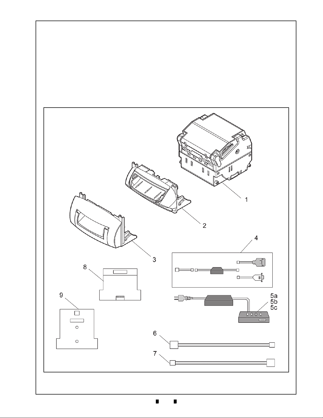
7-1
Taiko™ Series
7 EXPLODED VIEWS AND PARTS LISTS
Entire Taiko Unit Exploded View
Figure 7-1 Entire Taiko Unit Exploded View
Banknote Acceptor
Section 7
This section provides product exploded views and
parts lists for the Taiko
(PUB-7/11
lowing information.
®
) Series. This section contains the fol-
™ Banknote Acceptor
• Primary Taiko Unit Exploded View
• Complete Taiko Unit Exploded View
• Taiko Bezel Unit Exploded View.
P/N 960-100175R_Rev. 4 {EDP #200824} © 2013, Japan CashMachine Co., Limited
Page 64

7-2
Section 7 Taiko™ Series Banknote Acceptor Exploded Views and Parts Lists
Primary Taiko PUB-7/11 Unit Parts List
Table 7-1 Primary Taiko PUB-7/11 Unit Parts List
Ref No. EDP No. JAC Part No. Description Remark
1
-- --
-- -- PUB-11 Unit
PUB-7 Unit
2-- --PUB-7 Bezel
3-- --PUB-11 Bezel
4
116488 400-100573RA
TAIKO Harness B (Option)
G00172 ← Order JCMEu # Download Dongle
5a 116125 501-000187RA JCM Power Supply Unit (Option)
5b G00205 ← Order JCMEu # UAC Power Supply
5c G00176 ← Order JCMEu # MIB 232 Power Supply
127527 400-100551RA
6
G00183 ← Order JCMEu # Harness (for UAC or MIB 232 PSU)
TAIKO Harness A (Option)
G00182 ← Order JCMEu # Harness (for ccTalk)
7 124528 400-100589RA Clone Harness (Option)
8 119581 501-100200RA KS-070 Calibration Paper
9 197917 501-100256R KS-088 Calibration Paper
(See Figure 7-2 for individual parts)
(See Figure 7-2 for individual parts)
(See Figure 7-3 for individual piece
parts)
(See Figure 7-3 for individual piece
parts)
Assembly for loading Software from
a PC or Palm Pilot
For connecting PUB-7/11 Unit to
Power Supply Unit
For Cloning Units
For Calibrating Units
For Calibrating PUB-7-11 Units that
contain Barcode Coupon reading
capabilities.
®
P/N 960-100175R_Rev. 4 {EDP #200824} © 2013, Japan CashMachine Co., Limited
Page 65

7-3
Exploded Views and Parts Lists Taiko™ Series Banknote Acceptor Section 7
Figure 7-2 Complete Taiko PUB-7/11 Unit Exploded View
Complete Taiko Unit Exploded View
P/N 960-100175R_Rev. 4 {EDP #200824} © 2013, Japan CashMachine Co., Limited
Page 66

7-4
Section 7 Taiko™ Series Banknote Acceptor Exploded Views and Parts Lists
Complete Taiko PUB-7/11 Units Parts List
Table 7-2 Complete Taiko PUB-7/11 Units Parts List
Ref No. EDP No. JAC Part No. Description Qty Remark
1 115543 451-100102RA Entrance Solenoid 1
2 115544 451-100103RA
3 114977 400-100558RA
4 114978 400-100559RA
5 114980 400-100560RA
6 115484 250-100549RA
7 115485 250-100550RA
8 115486 250-100551RA
9 115487 250-100552RA
10 115488 250-100553RA Lower Guide Lock Spring 4
11 115511 250-100554RA
13 110923 900-100987RA
14 110914 900-100988RA
15 110915 900-100989RA
16 120664 550-100646RA
17 110924 900-100990RA
18 110925 900-100991RA
19 115509 250-100555RA
20 115510 250-100556RA
21 115491
23 115493
200-200285R Solenoid Bracket (B) 1
200-200287R Solenoid Bracket 1
24 110865 900-100992RA
25 110866 900-100993RA
26 110867 900-100994RA
27 110868 900-100995RA
28 110869 900-100996RA
29 110870 900-100997RA
30 110871 900-100998RA
31 110872 900-200136RA Upper Guide Cover 1
32 110873 900-101000RA
33 110874 900-101001RA
34 110875 900-101002RA
35 110876 900-101003RA
36 110877 900-101004RA
37 110878 900-101005RA
38 110879 550-100613RA
39 110880 900-101006RA
40 110881
200-200288R Lever Bushing (A) 2
42 110885 550-100614RA
Exit Solenoid 1
Relay Harness (14P) 1
PI Harness (3P) 1
Relay Harness 2 (4P) 1
Pinch Roller Spring (A) 8
Pinch Roller Spring (B) 8
Solenoid Spring 2
Magnetic Roller Spring 2
Lock Spring 2
Worm Gear 1
Idle Gear 1
Gear Guide 6
Feed Roller Assy. 2
Worm Gear Wheel 1
Drive Gear 2
Shutter Sensor Spring 1
Shutter Spring 1
Gear Box B 1
Gear Box A 1
Center Guide A 1
Center Guide B 1
Center Guide Right 1
Center Guide Left 1
Upper Guide 1
Side Cover Left 1
Side Cover Right 1
Guide Lever A 1
Guide Lever B 1
Center Guide C 1
Rear Guide 1
Drive Pulley 2
Pinch Roller 14
Dummy Head 1
Used in PUB-11 Only
For use only in NONParallel Interfaced Units
(See Table A-4 & Table A5 on page A-4 of Appendix
A in this Service Manual)
Used only in PUB-7
WITHOUT Barcode Sensor
capability
P/N 960-100175R_Rev. 4 {EDP #200824} © 2013, Japan CashMachine Co., Limited
Page 67
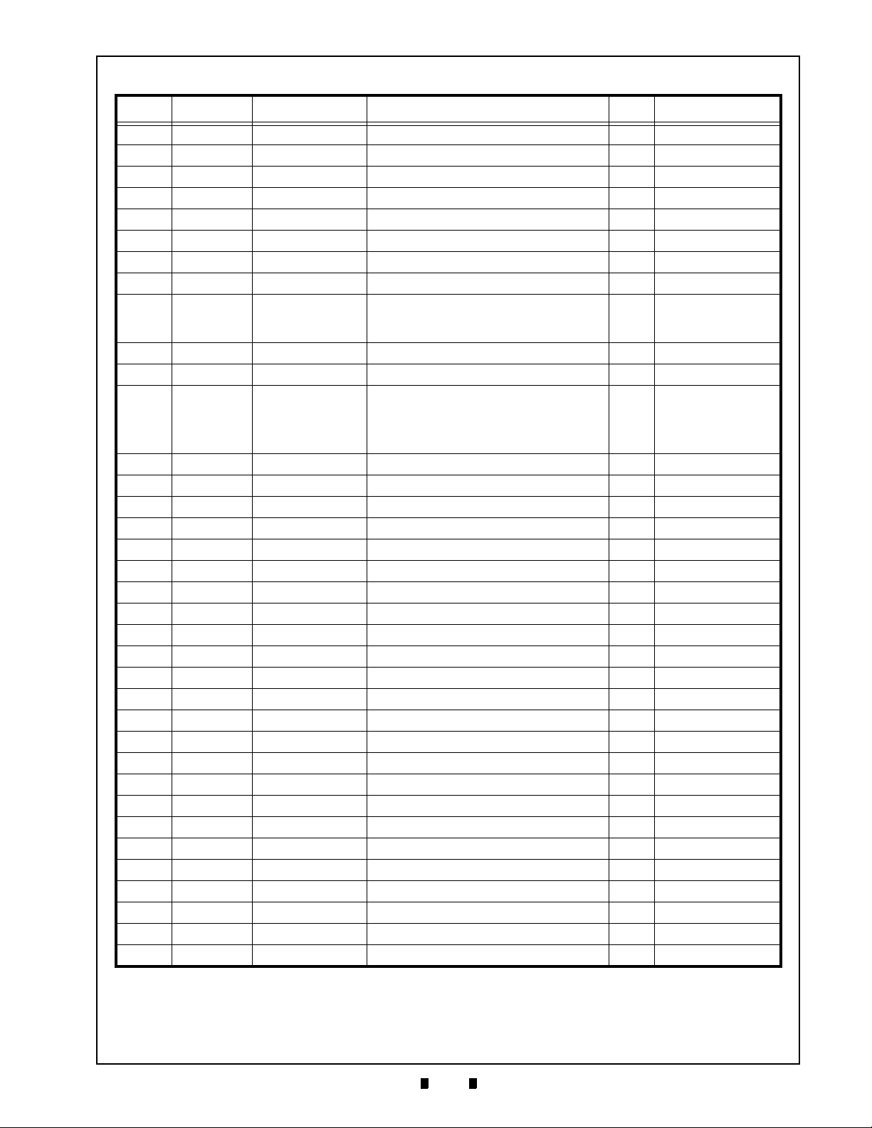
7-5
Exploded Views and Parts Lists Taiko™ Series Banknote Acceptor Section 7
Table 7-2 Complete Taiko PUB-7/11 Units Parts List (Continued)
Ref No. EDP No. JAC Part No. Description Qty Remark
44 110889 900-101008RA Lower Guide Cover 1
45 110890 250-100557RA
46 110892 900-101009RA
47 127512 900-101045RA
48 110894 200-200290RA
49 110895 200-200379RA
50 110896 200-200380RA
52 110898 200-200293RA
53 131655 550-100615RA
54 110900 900-200137RA Harness Cover 2
55 110903 900-101011RA
56 110904 900-101024RA Magnetic Head Roller 1
57 110906 900-101025RA Lower Base 1
58 110907 900-101012RA
59 110908 900-101013RA
60 110909 900-101014RA
61 110910 900-101015RA
62 110911 900-101016RA
64 110955 200-200381RA
65 115494 550-100615RA
66 115495 200-200294RA
67 115496 900-101017RA
68 115497 900-101018RA
69 115498 900-101019RA
70 115499 900-101020RA
71 115500 900-101021RA
72 115501 200-200295RA
73 097342 200-200296RA
74 115502 900-101022RA
75 115503 900-101023RA
77 115507 200-200297RA
78 115490 200-200298RA
79 115505 200-200299RA
80 115956 200-200300RA
81 115489 200-200301RA
82 115508 250-100558RA
Spring Guide 2
Lower Guide 1
Idle Slider 2
Clamp B 2
Lever Link Left 1
Lever Link Right 1
Lower Guide Lock 2
Magnetic Head Holder 1
Spring Stopper 1
Prism (A) 1
Prism (B) 1
Prism (C) 2
Right Guide 1
Prism (D) 2
Sensor Lever 1
Drive Pulley (F) 2
Shutter Sensor lever 1
Exit Prism (A) 2
Exit Prism (B) Left 1
Exit Prism (B) Right 1
Guide Lever Link Right 1
Guide Lever Link Left 1
Lever Bushing (B) 2
Locking Lever 2
Reject Roller (F) 2
Reject Roller 2
Solenoid Shaft 2
Pinch Roller Shaft 4
Pinch Roller Shaft (B) 2
Sensor Lever Shaft 1
Drive Gear Shaft 1
Sensor Lever Spring 1
Used only in PUB-7 Units
NOT containing a Barcode
Sensor or operating at 12/
24Volts
Used only in PUB-7/11
Units NOT containing a
Barcode Sensor.
(See Table A-4 & Table A5 on page A-4 of Appendix
A in this Service Manual)
P/N 960-100175R_Rev. 4 {EDP #200824} © 2013, Japan CashMachine Co., Limited
Page 68

7-6
Section 7 Taiko™ Series Banknote Acceptor Exploded Views and Parts Lists
Table 7-2 Complete Taiko PUB-7/11 Units Parts List (Continued)
Ref No. EDP No. JAC Part No. Description Qty Remark
Used in PUB EDP
109360 300-100422RA CPU Board, Pub-7, TWN/GBR/SCO 1
137778 300-500011RA CPU Board, Pub -7/11, USA 1
CPU Board, Pub -7/11, USA, W/O D19
Poly Vinyl Slider (OEM for ICA)
84
148060 300-000007R
136375 300-000008R CPU Board, Pub-7, ID001/004 EUR 1
189025 300-000009R CPU Board, Pub-7, 12V/24V EUR 1
85 137777 300-500020RA Sensor Board 1
86 114831 300-100426RA
88 082040 186-261006RA
89 003705
100-100029R Ø2 E-Ring Ø2 4
90 090776 200-200302RA
Interrupter Board 1
2.6x6 Phillips, Self Tightening, Pan Head
Screw
Ø2x14 Parallel Pin
91 006022 171-200040RA M2x4 Flat Head Screw 2
92 072361 200-200303RA
93 062887 186-200010RA
94 104019 200-200304RA
95 006026
142-306005 3x6x0.5 Flat Washer 1
97 057260 186-265000RA
99 116015 900-026508RA
100 107111 189-100310RA
101 092229 171-300008RA
102 109658 200-200305RA
105 006244 171-200103RA
106 003704 100-100042RA
107 116909 189-261000RA
108 115545 550-100647RA
109 127557 200-200306RA
110 127555 200-200307RA
114 127512 200-200385RA
115 127511 250-100617RA
Ø3x10 Parallel Pin 1
M2x10 Phillips Self Tightening Pan Head
Screw
Ø1.6x8 Parallel Pin 3
M2.6x5 Phillips Self Tightening Pan Head
Screw
Ø2x6.5x0.8 Polly Vinyl Slider 6
M3x10 Phillips Self Tightening Binding
Screw
M3x8 Phillips Self Tightening Flat Head
Screw
M3x16 Parallel Pin 4
M2x3 Pan Head Screw 4
Ø1.5 E-Ring 4
M2.6x10 Phillips Self Tightening Pan
Head Screw
Transport Motor Assy. 1
Bezel Installation Plate Right 1
Bezel Installation Plate Left 1
Idle Slider 2
Idle Roller Spring 2
116 127519 550-100618RA Drive Pulley Assembly 2
117 127518 550-100619RA Drive Pulley (F) Assembly 2
122 127513 200-200307RA Clamp (A-N) 2
#121383 Only (for use in
early PUB-7 Versions only)
Used in Standard PUB
7-11 Units for all Countries
Used in PUB EDP
#148061 Only (e.g., Diode
1
D19 was removed)
Used in PUB EDP
#139238 Only (for ID-001/
044 Parallel Interface for all
Countries)
Used in PUB EDP
#189306 & #195059 Only
(for 12/24Volt Units only)
16
For PUB-7-11 Units
containing a Barcode
1
Sensor
For Standard PUB-7-11
Units without a Barcode
2
Sensor
2
5
6
2
4
For use with Items 38 & 75
on page 7-4 of this Section
For use with Items 65 & 74
on page 7-5 of this Section
P/N 960-100175R_Rev. 4 {EDP #200824} © 2013, Japan CashMachine Co., Limited
Page 69

7-7
Exploded Views and Parts Lists Taiko™ Series Banknote Acceptor Section 7
Table 7-2 Complete Taiko PUB-7/11 Units Parts List (Continued)
Ref No. EDP No. JAC Part No. Description Qty Remark
130880 300-200130RA
189072 300-000010R
123
189071 ← Order by EDP #
Magnetic (MAG) Sensor Board 1
VC/MS Conversion Sensor Board
(no MAG Sensor)
VC/MS Conversion Sesor Board
(with MAG Sensor)
195055 300-000011R Barcode Sensor Board (no MAG Sensor) 1
124 074666 200-200382RA 3x15 Parallel Pin 1
125 131072 400-100590RA
MAG Sensor Relay Harness 1
126 003707 100-100043R Ø3 E-Ring 3
127 189305 ← Order by EDP #
Power Relay Harness 1
For use only in PUB-11
NOT operating at 12/24V
For use with PUB-7 when
1
operating at 12/24V
For use only in PUB-11
1
operating at 12/24V
For use with PUB-11 with
Barcode Sensor capability
For PUB-11 Only
P/N 960-100175R_Rev. 4 {EDP #200824} © 2013, Japan CashMachine Co., Limited
Page 70

7-8
Section 7 Taiko™ Series Banknote Acceptor Exploded Views and Parts Lists
Figure 7-3 Taiko PUB-7/11 Bezel Unit Exploded View
Taiko Bezel Unit Exploded View
P/N 960-100175R_Rev. 4 {EDP #200824} © 2013, Japan CashMachine Co., Limited
Page 71

7-9
Exploded Views and Parts Lists Taiko™ Series Banknote Acceptor Section 7
Taiko PUB-7/11 Bezel Units Parts List
Table 7-3 Taiko PUB-7/11 Bezel Units Parts List
Ref No. EDP No. JAC Part No. Description Qty Remark
201 110884 200-200384RA Bezel 1
Type 1
Type 2
1
Type 3
Type 5
2
2
Intended for OEM
Development
2
202
110897 900-100981RA
118069 900-100983RA
PUB-7 Bezel Guide for EURO (68mm) 1
PUB-7 Bezel Guide for GBR/SCO
(76mm)
121519 900-100984RA PUB-7 Bezel Guide (71mm) 1
20 3 131111 900-200135RA PUB-11 US Bezel Guide (67mm) 1
204 131108 900-100976RA US Bezel A (67mm) 1
205 131109 900-100977RA
206 115492 200-200383RA
207 127556 200-200308RA
208 116908 140-031033RA
209 116910 189-000410RA
210 080908 181-000036RA
211 006037
212 143685
213 143686
186-400015R 3x12 Pan Head with Sems Screw 2
200-000339R Bezel Plate Assy 1
200-000340R Bezel Hook 1
143147 902-100492RA
214
201847 ← Order by EDP #
US Bezel B (37mm) 1
Bezel Bracket 2
Bezel mounting Hook 1
Hexagonal Nut M4 2
M4x10 P Phillips Self Tightening Binding
Screw
3x6 Phillips Self Tightening Binding
Screw
Bezel (V) 1
Bezel (V) 1
215 005332 175-330005 M3x5 Flat Head Screw 2
216 107111 189-100310RA
M3x10 Phillips Self Tightening Binding
Screw
P/N 960-100175R_Rev. 4 {EDP #200824} © 2013, Japan CashMachine Co., Limited
Page 72

7-10
Section 7 Taiko™ Series Banknote Acceptor Exploded Views and Parts Lists
Figure 7-4 Taiko EBA Type Bezel Unit Exploded View
Taiko EBA Type Bezel Unit Exploded View
P/N 960-100175R_Rev. 4 {EDP #200824} © 2013, Japan CashMachine Co., Limited
Page 73

7-11
Exploded Views and Parts Lists Taiko™ Series Banknote Acceptor Section 7
Taiko EBA Type Bezel Units Parts List
Table 7-4 Taiko EBA Type Bezel Units Parts List
Ref No. EDP No. JAC Part No. Description Qty Remark
301 127556 Face Fix Hook 1
302 187815
303 187817
187819
304
187822
187824 Guide 76 L 1
187821
305
187823
187825 Guide 76 R 1
306 149635 M3x4 Flat Small Head Screw 2
307 001767
308 131154
EBA Type Bezel A 1
EBA Type Bezel B 1
Guide 68 L 1
Guide 71 L 1
Guide 68 R 1
Guide 71 R 1
M3x5 Screw with Washer (Small) 2
2x4 Phillips, Self Tightening, Flat Screw 4
Width 71
Width 76
Width 71
Width 76
P/N 960-100175R_Rev. 4 {EDP #200824} © 2013, Japan CashMachine Co., Limited
Page 74

7-12
Section 7 Taiko™ Series Banknote Acceptor Exploded Views and Parts Lists
THIS PAGE INTENTIONALLY LEFT BLANK
P/N 960-100175R_Rev. 4 {EDP #200824} © 2013, Japan CashMachine Co., Limited
Page 75

Taiko™ Series
8-1
Banknote Acceptor
8 INDEX
B
Banknote Acceptor
general information describing a… 1-1
C
Calibration
procedures for… 6-7
Cautions
special boxed areas providing important safety
information… 1-3
Cleaning
methods of, and equipment required for… 2-6
Cloning
procedures for… 6-5
Communications
criteria regarding receipt of… 3-1
Contact Information
Address and Telephone Numbers for… 1-11
D
Dimensions
entire unit clearance
illustrated drawing for… 1-8; 1-9
DIP Switch Configurations
setting for… 2-3
Disassembly/Reassembly
instructions for… 4-1
Download and Installation
Workbench Tool Requirements for… 6-1
Driver Installation
Instructions for performing… 6-2
E
Exploded View
illustrations of… 7-1
External Power Supply
Part No. for… 6-3
F
Flowchart
Operational
symbol language describing flow functions… 2-15; 2-16
I
Installation
steps required for… 2-1
J
Jam
Banknote
clearing… 2-2
Section 8
N
Navigation
within manual
procedure for… 1-1
P
Palm Pilot Handheld
types & software requirements… 6-2
Performance Test
instruction for… 6-7
Precautionary Symbols
types of… 1-2
Primary Features
Taiko Series… 1-3
R
Reference Paper
Part No. for… 6-7
S
Safety
pictographs indicating
1 to 3 symbols inside boxed area… 1-1
Special Notes
italic text highlights
finger points to… 1-1
Specifications
electrical… 1-7
environmental… 1-6
model number… 1-2
structural… 1-7
technical… 1-6
Steps
sequential numbering of… 1-1
Symbols
Precautionary
definitions of… 1-2
System Wiring Diagram
Schematic diagram of… 5-1; 5-2; 5-3; 5-4
T
Taiko PUB-7/11 Unit
photo of a… 1-1
Tool Requirements
workbench… 6-1
Troubleshooting
Instructions for… A-1
W
Wiring Diagram
system & individual primary part… 5-1
P/N 960-100175R_Rev. 4 {EDP #200824} © 2013, Japan CashMachine Co., Limited
Page 76

8-2
Taiko™ Series Banknote Acceptor Index Index
THIS PAGE INTENTIONALLY LEFT BLANK
P/N 960-100175R_Rev. 4 {EDP #200824} © 2013, Japan CashMachine Co., Limited
Page 77

A-1
Taiko™ Series
A TROUBLESHOOTING
Banknote Acceptor
Appendix A
This section provides Troubleshooting instructions
for the Taiko
Series. This section contains the following infor
™ Banknote Acceptor (PUB-7/11)
-
mation:
• Introduction
• Troubleshooting Overview
• Fault Table Listings
• Usage Specifications
• Error Codes and Conditions.
Introduction
Most Banknote Validator failures are due to minor
causes. Before replacing any parts, make sure that
all assembly and Circuit Board Connectors are
properly fitted and the Harnesses are properly con
nected.
Faulty Banknote acceptance by the Validator portion of the Unit is often caused when dust or Iron
powder adheres to the Identification Sensor, Mag
netic Sensor or Transport Belt. Clean the Acceptor
section first, then observe the operating state of the
Validator in detail when re-initializing power. This
observation is important in locating any failure
Table A -1 General Fault Conditions
-
causes and the possible fault area. If the Validator
Head has to be repaired by disassembling it,
always re-calibrate the Sensors following a repair.
Perform all repairs by referring to Calibration and
Testing in Section 6 of this manual, and Disassem
bly/Reassembly in Section 4 of this manual.
Troubleshooting Overview
This product allows the operator to perform fault
diagnosis by checking various fault Table listings
against the symptom, and survey the cause(s) of
any failure occurrences during the process.
After determining the cause of the failure, execute
the Performance Test, perform a Sensor re-adjust
ment and then repair the Unit by replacing any
appropriate parts deemed necessary.
Fault Table Listings
Table A -1 through Tabl e A-3 each list the various
possible Taiko fault conditions that can occur and
the necessary actions required to correct them.
Table A -6 lists the Red LED Color Flash Error
Code that may occur during normal and dynamic
testing operations.
-
-
Symptoms/Error
Messages
Banknote Acceptor is
not working
(does not accept any
Banknotes).
P/N 960-100175R_Rev. 4 {EDP #200824} © 2013, Japan CashMachine Co., Limited
Possible Fault Causes Corrective Action Required
Power is not supplied to the
CPU and/or Sensor Board
The Entrance Sensor is not
working or there is a foreign
Acceptor
Incorrect Connection
Correct Software is not
downloaded
Failure
object lodged within the
entrance area
Verify that the specified Voltage and Ground Connections are supplied to
appropriate Pins of the Interface Connector.
Verify that all Harnesses and Connectors are properly fitted.
Verify if any Connector Pins are bent, missing, or broken.
Verify if the specified Voltage is being supplied to the appropriate Pin
(See "Power Harness Wiring Procedure” on page 2-2 of Section 2 in this
Service Manual).
Download the appropriate Software to the Taiko Unit (See "Software
Downloading Procedure” on page 6-2 of Section 6 in this Service
Manual).
Perform the Acceptance Test (See "Performance Test Diagnostics” on
page 6-7 of Section 6 in this Service Manual). If the Acceptance Test
result is unacceptable, replace the CPU and/or Sensor Circuit Board
(See "CPU Circuit Board Removal"and "Sensor Circuit Board Removal”
on page 4-2 of Section 4 in this Service Manual). Once the CPU/Sensor
Board is replaced, perform a complete Calibration Procedure (See the
"Calibration Procedures” on page 6-7 of Section 6 in this Service
Manual).
Remove ANY foreign objects in the Transport Path and clean the
Entrance Sensor (See "Cleaning Procedures” on page 2-6 in Section 2
of this Service Manual). Perform the Aging Test (See No.3 "Aging Test
Procedure” on page 6-8 in Section 6 of this Service Manual). If any
Sensor error is detected, replace the CPU/Sensor Board (See "CPU
Circuit Board Removal"in Section 4 of this Service Manual).
Page 78

A-2
Appendix A Taiko™ Series Banknote Acceptor TroubleShooting
Table A -1 General Fault Conditions (Continued)
Symptoms/Error
Messages
Banknote jams occur
often.
(Continued)
Banknote jams occur
often.
Acceptance rates is
All Banknotes being
low
returned
Motor rotates a few
times and stops
Can not enter the
TEST mode.
Possible Fault Causes Corrective Action Required
Clean the Feed or Pinch Roller (See "Cleaning Procedures” on page 2-6
A Feed or Pinch Roller is
soiled or broken
The Feed or Pinch Roller
Spring is missing or loose
A foreign object exists on the
Transport Path
Incorrect Bezel width for
Banknote being inserted
The Banknote width is 83mm
or larger or 62mm or smaller
(Out of Taiko Design
Specification)
Rollers, Belts and Lenses are
soiled with dirt
Sensors need adjustment
Taiko unit has not been
adjusted following
disassembly
The Software revision is out of
The Software program for the
Banknote inserted is not
The Loaded Software does not
match the currency being
DIP Switch Settings are wrong
The Host Command is set to
A CPU/Sensor failure has
Sensors needs to be cleaned
CPU Circuit Board failure
DIP Switch Settings are wrong
date
supported
validated
“inhibit” Mode
occurred
and readjusted
A DIP Switch is
suspect as broken
CPU Board failure.
in Section 2 of this Service Manual). If any roller corruption is found,
replace the defective Roller; then perform the "Sensor Circuit Board
Removal” on page 4-2 of Section 4 in this Service Manual.
Examine the Feed and/or Pinch Roller Spring’s condition and replace it
as required if damage or fatigue is noted.
Remove ANY foreign object(s) found on the Transport Path and clean
the path (See "Clearing a Banknote Jam” on page 2-2 of Section 2 in this
Service Manual).
Change the Bezel Guide to represent the correct Banknote width
specification (See "Installing the PUB-7/11 Taiko Bezel” on page 2-1 of
Section 2 in this Service Manual).
Use only the acceptable Banknote width ("Technical Specifications” on
page 1-6 of Section 1 in this Service Manual).
Clean the Rollers, Belts and Lenses ("Cleaning Procedures” on page 2-6
in Section 2 of this Service Manual, and perform the "Calibration
Procedures” on page 6-7 in Section 6 of this Service Manual).
Adjust the Taiko Unit Sensors (See "Cleaning Procedures” on page 2-6
in Section 2 of this Manual and perform the "Calibration Procedures” on
page 6-7 of Section 6 in this Service Manual).
Readjust the Taiko Unit (See "Cleaning Procedures” on page 2-6 in
Section 2 of this Service Manual and perform the "Calibration
Procedures” on page 6-7 in Section 6 of this Service Manual).
Download and install the latest Software Program (See "Software
Downloading Procedure” on page 6-2 in Section 6 of this Service
Manual).
Verify if the denomination’s value issued year is appropriate for that
specified in the specific Country’s Software Information Sheet (See
Table 1-2, “Taiko PUB-7/11 Technical Specification,” on page 1-6 of
Section 1 in this Service Manual).
Download the appropriate Software program to the Taiko Unit (See
"Software Downloading Procedure” on page 6-2 in Section 6 of this
Service Manual).
Reset the Acceptance DIP Switch settings correctly and reapply power
to the Unit (See "DIP Switch Configurations” on page 2-3 in Section 2 of
this Service Manual).
Reset the Host Command to the “Accept” Mode.
Replace the CPU and/or Sensor Circuit Board (See "CPU Circuit Board
Removal" and "Sensor Circuit Board Removal” on page 4-2 of Section 4
in this Service Manual). Once the CPU/Sensor Board is replace, perform
a complete Calibration Procedure (See "Calibration Procedures” on
page 6-7 in Section 6 of this Service Manual).
Readjust the Taiko Unit Sensors (See "Cleaning Procedures” on page 26 in Section 2 of this Service Manual and perform the "Calibration
Procedures” on page 6-7 in Section 6 of this Service Manual).
Replace the CPU Circuit Board (See "CPU Circuit Board Removal"
procedure on page 4-1 of Section 4 in this Service Manual).
Reset the Acceptance DIP Switch settings correctly and reapply power
to the Unit (See "DIP Switch Configurations” on page 2-3 in Section 2 of
this Service Manual).
Perform the "DIP Switch Tests” on page 6-8 of Section 6 in this Service
Manual. If the DIP Switch Test result is good, replace the CPU Circuit
Board (See "CPU Circuit Board Removal" procedure in Section 4 of this
Service Manual). Once the CPU Circuit Board is replace, perform a
complete Calibration Procedure (See "Calibration Procedures” on
page 6-7 in Section 6 of this Service Manual).
Replace the CPU Circuit Board (See "CPU Circuit Board Removal"
procedure in Section 4 of this Service Manual). Once the CPU Circuit
Board is replaced, perform a complete Calibration Procedure (See
"Calibration Procedures” on page 6-7 in Section 6 of this Service
Manual).
P/N 960-100175R_Rev. 4 {EDP #200824} © 2013, Japan CashMachine Co., Limited
Page 79
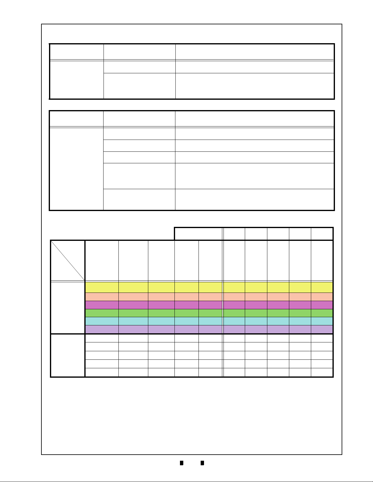
A-3
TroubleShooting Taiko™ Series Banknote Acceptor Appendix A
Symptoms/Error
Messages
Adjustment Error
Symptoms/Error
Messages
Cannot
communicate with the
Host Machine.
Tab le A-2 Adjustment Fault Conditions
Possible Fault Causes Corrective Action Required
Wrong Reference Paper being
CPU and/or Sensor Board
used
Failure
Use the correct KS-070 or KS-88 specified Reference Paper for
calibrating the Taiko Unit.
Replace the CPU Circuit Board (See "CPU Circuit Board Removal"
procedure in Section 4 of this Service Manual). Once the CPU Circuit
Board is replaced, perform a complete Calibration Procedure (See
"Calibration Procedures” on page 6-7 in Section 6 of this Service
Manual).
Table A -3 Communication Fault Conditions
Possible Fault Causes Corrective Action Required
DIP Switch settings are
incorrect
Connectors are off
or loosely fitted
Damaged Connector Pin(s)
CPU and/or Sensor Board is
corrupted
Incorrect Interface
Set all DIP Switches to OFF and re-apply power to the Taiko Unit.
Firmly re-seat all of the Communication Connectors.
Check for any bent, missing or damaged Pins in the Connector Plugs and
mating Receptacles. Straighten or replace Pins or the entire Connector.
Replace the CPU and/or Sensor Circuit Board (See "CPU Circuit Board
Removal" and "Sensor Circuit Board Removal” on page 4-2 of Section 4
in this Service Manual). Once the CPU/Sensor Board is replace, perform
a complete Calibration Procedure (See "Calibration Procedures” on
page 6-7 in Section 6 of this Service Manual).
Verify that the correct interface between the Host Machine and the
Banknote Acceptor is being used. If wrong, reset the Interface DIP
Switches accordingly ((See "DIP Switch Configurations” on page 2-3 in
Section 2 of this Service Manual).
Function
Model
PUB-7
PUB-11
Table A -4 Taiko Usage Specifications (Part 1)
EDP No. →
Pin
Assignment
Early
Versio n.
Standard Serial 12V - -
Standard Serial 12V Available -
Standard Serial 12V - Available
Standard Parallel 12V - -
Standard Serial 12V/24V - -
Standard Serial 12V - -
Standard Serial 12V - -
Standard Serial 12V - Available
Standard Parallel 12V - -
Standard Serial 12V/24V - -
Interface
Serial 12V - -
Input
Power
Source
Barcode
Sensor
ICA
(OEM)
110871 139230 131655 110904 196601
Upper
Guide
Upper
Guide
Parallel
Mag
Head
Holder
Mag
Head
Roller
Barcode
Sensor
Block
O X O O X
O X O O X
O X X X O
O X O O X
X O O O X
O X X O X
O X X O X
O X X O X
O X X O X
X O X O X
O X X O X
P/N 960-100175R_Rev. 4 {EDP #200824} © 2013, Japan CashMachine Co., Limited
Page 80

A-4
Appendix A Taiko™ Series Banknote Acceptor TroubleShooting
Table A -5 Taiko Usage Specifications (Part 2)
EDP No. →
Function
Model
109360 137778 148060 136375 189025 900776 130880 189072 189071 195055 131072 189305
CPU
Board
Early
Pin
Assign-
ment
CPU
Board
CPU
Board
for ICA
CPU
Board
for
Parallel
I/F
CPU
Board
for
12V/
24V
O X X X X
X O X X X
PUB-7
X O X X X
X X O X X
X X X O X
X X X X O
XOXXX
XOXXX
PUB-11
XXOXX
XXXOX
XXXXO
Error Codes and Conditions
Table A -6 lists the Red Error Code flash sequence
definitions displayed by the Taiko Front Panel
LED Indicator.
Table A -6 Red LED Error Code Flash Definitions
Ø2x14
Parallel
Pin
Qty. 2
Qty. 2
Qty. 1
Qty. 2
Qty. 2
Qty. 2
Qty. 2
Qty. 2
Qty. 2
Qty. 2
Qty. 2
MAG
Board
VC/MS
Board
MAG)
(No
VC/MS
Board
(With
MAG)
Barcode
Sensor
Board
MAG
Relay
Harness
Power
Relay
Harness
X X X X X X
X X X X X X
X X X O X X
X X X X X X
X X X X X X
X O X X X O
OXX X OX
OXX X OX
OXX X OX
OXX X OX
XXOXXO
Red
Flashes
Error Indicated
2 ROM Error
3 Banknote Jam inside Ejection Slot
4 Banknote remains inside Transport Path
5 EEPROM Read/Write Error
6 Motor Error
8 Entrance Solenoid Error
9 Exit Solenoid Error
12 Sensor operation at an abnormal timing
P/N 960-100175R_Rev. 4 {EDP #200824} © 2013, Japan CashMachine Co., Limited
Page 81

B-1
Taiko™ Series
Banknote Acceptor
Appendix B
BGLOSSARY
A
1 Acceptor – a term used in Communications Section 3 referencing functions sent to, and
received from the Banknote Acceptor by Software commands … See Page 1-1
2 Anti-stringing Mechanism – a method of preventing Banknotes from being illegally
removed from a validator using a string or wire to retrieve it
once it has been accepted by the Unit … See Page 1-6
B
3 Bezel – The Banknote input Bezel portion of a Taiko PUB-7/11 Unit … See Page 2-1
D
4 DIP Switch – acronym for a Dual In-line Package Switch - a Printed Circuit Board mountable
two-position Slide Switch Package containing up to 16 individual ON/OFF
throw Switches … See Page 2-3
E
5 E-Clip – a semicircular clip designed to fit into a shaft groove to retain a component in
place … See Page 4-1
6 EEPROM – acronym for Erasable Programmable Read Only Memory … See Page 6-7
F
7 Flash Memory – electronically programmable memory integrated circuits that can be reused
without requiring special erasure procedures … See Page 6-1
I
8 Identification Sensor – optical sensors used for reading images on Banknotes for comparison
to recorded known image information … See Page A-1
9 Interface – also abbreviated as I/F. Signifies and identifies the Circuitry and/or Protocol for a
specific communications standard … See Page 2-5
M
10 MAG Board – a PUB-11 Circuit Board specifically designed to detect Magnetic Ink resident
on specific Country’s Banknotes … See Page 4-2
11 Magnetic Sensor – a Sensor used to detect the Magnetic Ink present on certain Country’s
Banknote denominations … See Page A-1
12 MDB – acronym for Machine Data Bus … See Page 2-5
P/N 960-100175R_Rev. 4 {EDP #200824} © 2013, Japan CashMachine Co., Limited
Page 82

B-2
Appendix B Taiko™ Series Banknote Acceptor P
P
13 Pictograph – small internationally recognized safety and attentions Symbols placed to the left
of Notes, Cautions and Warnings throughout this Manual … See Page 1-1
14 PUB-7/11 – abbreviation for PUBlic House-Type/Type. Names for the original Taiko™ Beta
Test Site … See Page 1-1
S
15 Setting Mode – various selectable Modes available for setting specific operational conditions
in the Taiko PUB-7/11 Unit … See Page 2-4
P/N 960-100175R_Rev. 4 {EDP #200824} © 2013, Japan CashMachine Co., Limited
Page 83

Taiko™ Series Banknote Acceptor
P/N 960-100175R_Rev. 4 {EDP #200824} © 2013, Japan CashMachine Co., Limited
Page 84

Taiko™ Series Banknote Acceptor
Support: http://www.jcmglobal.com/en/contact/default.aspx Web-Site: http://www.jcmglobal.com
Issue #4045-SME-01-04
P/N 960-100175R_Rev. 4 {EDP #200824} © 2013, Japan CashMachine Co., Limited
 Loading...