

Page 1
1
Sunbeam
INSTRUCTION MANUAL
JCM
®
Page 2

2
CONTENTS
Introduction .......................................................................................................................... 3
Measurements & Useful Info
................................................................................................4
Effective Operation of Lock Levers
......................................................................................4
Seating System Components
..............................................................................................5
Important Safety Advice
....................................................................................................... 6
Important Safety Advice -(Accessories)
...............................................................................7
Important - Chest Harness Adjustment
...............................................................................8
Important - Lap Strap Safety
................................................................................................9
Footplate & Leg Length Adjustment
.................................................................................. 10
Adjusting the Tilt / Prone in Space
.....................................................................................11
Adjusting the Back Recline / Prone
....................................................................................12
Lateral Flexi & Lap Strap Adjustment
.................................................................................13
Adjusting the Headrest Position
.........................................................................................14
Operating the Rocking Mechanism
...................................................................................15
Adjusting the Seat Depth
................................................................................................... 16
Tray Fitting & Adjustment
................................................................................................... 17
Positioning on the 5 Star High-Low Base
..........................................................................18
Raising & Lowering - 5 Star Base
...................................................................................... 19
Cleaning & Care .............................................................................................................20
General Maintenance .....................................................................................................20
Servicing via Approved Repairer ...................................................................................21
Service Record Log .......................................................................................................22
Warranty .........................................................................................................................23
Inspecting & Reissuing of Equipment ...........................................................................24
Page 3

3
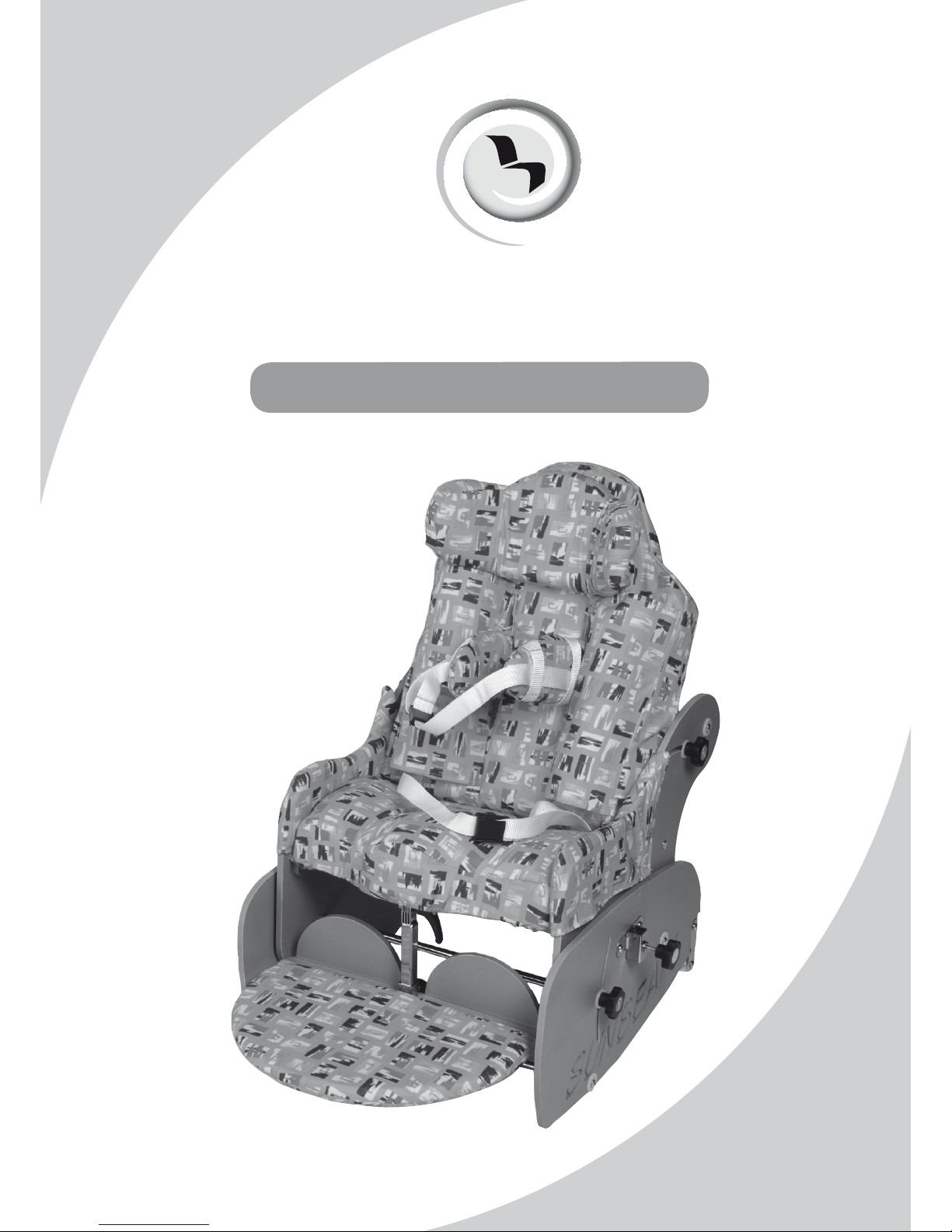
The Sunbeam is designed to provide comfort and postural support. The system is only
available in one size to suit children between the ages of 3 months and 3 years approximately.
The seating system is not intended for those who have significant athetosis.
This instruction manual contains very important information about the Sunbeam seating
system, how to use it safely and obtain the best results from it. Please read all the information
contained in this manual before using the chair and retain for future reference. Ensure
everyone using the equipment is aware of the contents of this manual and understands
how to use the equipment safely.
These instructions provide guidance on the adjustments for professionals, but they also
give information on how the equipment should be safely used, maintained, checked, and
correctly assembled by anyone who uses the seating system.
In every case the equipment should be supplied via qualified professionals who will have
adjusted the equipment, checked its compliance and tested it appropriately.
The seating system should only ever be adjusted by qualified professionals and persons
that are suitably trained. For further information please do not hesitate to contact us - all
contact details are on the back cover of the manual.
Thank you for purchasing our product, we
hope you enjoy your new seating system.
Introduction
Page 4
4
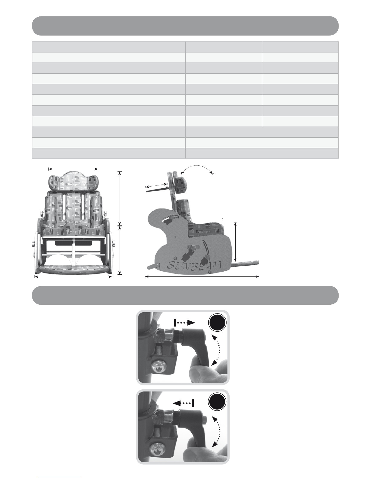
Never remove these levers
entirely as this will prevent
you from being able to
perform adjustments in the
future.
To use:
Turn the lever handle
clockwise to tighten or
anti clockwise to untighten.
To use the lever when an
obstruction is met:
Pull the handle of the
lever outwards, towards
you (A). This disables the
•
•
function of the lever.
Continue to hold the
lever out and reposition
the lever handle in a
suitable position past the
obstruction.
Release the handle to reengage the lever function
(B) and continue to
tighten or un-tighten in the
normal way.
Repeat this procedure in
areas where adjustment
is restricted due to an
obstruction.
•
•
•
Measurements & Useful Info
Measurements (cm) MIN MAX
A Seat Depth 15.0 27.5
B Seat to Headrest 25.0 45.0
C Seat to Footplate 0 28.0
D Seat Width (between laterals) 16.5 36.5
E Floor to Seat (high-low base) 56.0 70.0
F Tilt / Prone 5.0 ° -35 °
G Back Recline 15.0 ° -30 °
H Base Footprint 50 x 41
Max user weight 10.0kg
Weight of chair 14.4kg
H
C
F
G
A
B
E
D
H
Effective Operation of Lock Levers
A
B
Page 5
5
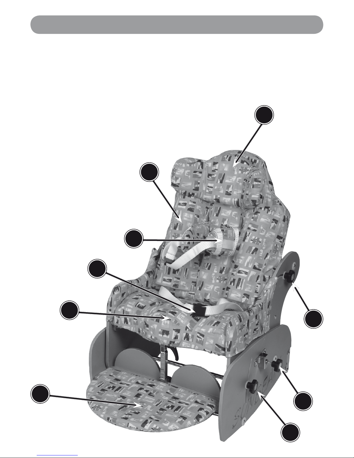
Seating System Components
A
B
C
D
G
F
H
E
A Headrest
B Side Rolls
C Flexi Supports
D Pelvic Strap
E Shaped Seat
F Footplate
G Locking Lever - Tilt in Space / Prone Function
H Locking Lever - Arm Rest Fixing
I Locking Lever - Back Recline Function
I
Page 6

6
Throughout the manual there are important points to note identified by the symbol:
!
Ensure all adjustment mechanisms are secure and in place before operation. If it is
likely that the hand-wheels will be repeatedly loosened, JCM can supply allen key bolts
as an alternative. We strongly recommend this if there is a danger from those in the
vicinity of the user.
All postural support straps and harnesses should be in place and properly adjusted to
the user, prior to usage of any kind (see pages 8 & 9).
Whilst the seating system is stable on a 5-degree slope, even in its most upright position,
it is not intended to be used in this manner. It is however, intended to be used on a level
flat floor, where movement is confined to a single room. For safety ALWAYS return the
product to a neutral position before moving (lower in height, level the seat, ensure the
back is upright etc).
Heavy items on the tray will affect stability. The fitting of anything other than the standard
JCM tray may substantially affect the stability of the seating system and should therefore
be checked before issue.
If at any time it is noted that areas of the users skin remain reddened after being out of the
seating system for around 10 minutes, urgently contact the qualified professional who
performed the hand over of the equipment. This may be a sign of excessive pressure
being exerted by the seating. This might occur in the initial use of a new seat where
further adjustment may be required, where the user has been badly placed, grown or
where an underlying medical problem exists. Review may be necessary in such cases
After completing any alterations ENSURE all nuts, bolts, knobs, hand wheels and other
fixings are securely tightened and in position, and that they are regularly checked as
part of the maintenance of the chair. Never over adjust or over tighten moving parts.
Keep all products away from excessive sources of heat, cigarettes and naked flames.
If you suspect that the system may be faulty, cease use of the equipment straight away
and immediately contact the organization who supplied the system. (JCMs contact
information can be found on the back cover).
The equipment will be labelled with important information. NEVER REMOVE these
information labels or allow them to be defaced, overlaid or altered.
All modifications, adjustments, reconditioning, repairs, disposal, and servicing of the
seating unit must ONLY be carried out by the agencies who supplied the equipment
(see pages 20-21).
•
•
•
•
•
•
•
•
•
•
Important Safety Advice
!
We at JCM are committed to producing products of the highest standard. All of our
products fulfil the essential safety and environmental requirements as defined in
the European Directives. However, improper use of the products will potentially put
the users at risk and therefore JCM strongly suggest that the following information
is strictly adhered to at all times.
Page 7

7
Important Safety Advice -(Accessories)
!
Moore Head Support
Should only be adjusted by a therapist or competent person who understands the product
and its principals. The prongs on the head support should never be tight around the head.
Check that the prongs are NOT set near the eyes or infringe behind the ears. The foam
covering the prongs should be inspected regularly and replaced if damaged.
Multi Adjustable Head support
Wings on the head support are ideally set at 45 degrees. Do NOT bring the wings in tight to
the head. Ensure that the head support is set in such away that the child cannot loop their
head around the wings and get stuck.
Flexi-Supports and Lateral Supports
Ensure the straps do not infringe on any feeding tubes the child may have.
Pommel
The pommel is designed to abduct the users knees to help keep the hips in a good position.
Do NOT use the pommel as a way of holding the user in the seat. Remove the pommel
when transferring the user in and out of the seat (not required for Star X Series.)
Foot Sandals and Straps
Should only be fixed when the user is wearing shoes or boots.
Tray
Do NOT use the tray as a way of securing children in a chair always ensure that the lap
strap and any other straps supplied are used. Ensure that the tray clips are secure on both
sides of the tray. If the tray is damaged, ensure that this will not be a hazard to the user.
Never leave hot items on the tray while children are unattended.
Page 8
8
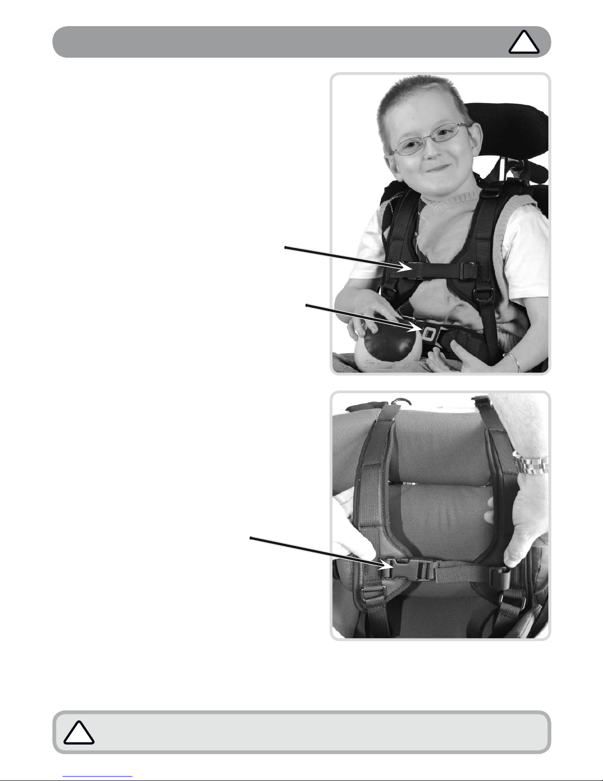
If there is any possible chance of the child getting the straps caught around
their neck, REMOVE THE HARNESS IMMEDIATELY.
!
Important - Chest Harness Adjustment
GREAT CARE should be taken when fitting
a chest harness and the following points
should always be followed:
The straps on the harness should never
be allowed to move close to or in any way
cause an obstruction to the childs neck.
The straps should never be fitted too tightly
and should be clear from any obstruction.
The cross strap on the chest harness
should always be adjusted prior to use
to ensure that it is no higher than the
middle of the users chest.
A lap strap should always be fitted if a
harness is being used to ensure the child
cannot slide down onto the cross strap.
Always ensure that the belts offer your
child both comfort and support. If the
childs clothing has been adjusted (i.e. a
jumper removed) the straps should be readjusted accordingly.
Fixing Onto Chair
The straps at the top of the harness should be
attached to the back frame of the chair. The
straps at the bottom of the harness should be
attached to the back of the seat frame.
Fastening of Belts
Feed the fabric belt through the
buckle on the strap.
The belts should be pulled through
enough to suitably support your
child whilst still being comfortable.
When this has been achieved the
buckle should be snapped closed
to secure the strap in place.
•
•
•
•
•
•
•
•
!
The same precautions highlighted here should be adhered to when using any form of
trunk supports or flexi supports with straps.
Page 9

9
Important - Lap Strap Safety
Incorrect fitting of lap straps can put the user at serious risk. When using lap
straps we recommend the following points should always be adhered to:
Lap straps must always be fitted at 45 degrees to the pelvis of the user.
Always check that the child’s pelvis is symmetrical and positioned securely at the back
of the seat.
Always ensure that the lap straps and chest harness hold the child securely and are
comfortable. Ensure they provide a snug fit, a simple rule of thumb is to allow two
fingers to be inserted between the belt and the childs body.
Never leave a child in a chair unattended without the lap strap being fastened.
A lap strap should always be fitted if a harness is being used.
When altering the angle between the seat and the back of the chair always re-adjust
the chest harness and lap strap accordingly to ensure all safety recommendations are
followed.
Harness and Lap Strap Positioning
This diagram shows the recommended positioning of the chest harness and lap straps:
•
•
•
•
•
•
!
Chest
Harness
Fitting
Lap Strap
Fitting
Lap Strap
Fitting
The cross
strap on the
chest harness
must be fitted
no higher than
the sternum
(mid chest).
All straps &
harnesses
must be
securely
fitted to the
back of the
chair.
Second
fixing for
four-point
lap strap
Page 10

10
Footplate & Leg Length Adjustment
A
B
Leg Length Adjustment
Lever (A) allows the operator to
position the footplate and cater for
the leg length of the child seated.
Turn lever (A) in an anticlockwise direction. Once loose
enough (do not remove levers
entirely) the footplate is free to
be manually slid up and down
the chrome leg.
Once a suitable footplate
position has been acquired the
user should lock it into place by
tightening the lever, turning in the
clockwise direction.
Angle Position of Footplate
Lever (B) allows the operator to
adjust the angle position of the
footplate.
Turn lever (B) in an anticlockwise direction. Once loose
enough (do not remove lever
entirely) the footplate is free to
be manually swung about the
point where the lever is located.
Once a suitable footplate
position has been acquired,
lock the footplate into place by
tightening the lever, turning in the
clockwise direction.
•
•
•
•
Page 11

11
The weight of your child is supported by the levers indicated. Ensure they are
locked of suitably at all times and thoroughly supported when adjusting.
!
The tilt in space should only be set to maximum when the chair is supervised
and your child is at rest. Activity in this position can potentially topple the chair.
!
Adjusting the Tilt / Prone in Space
The Sunbeam is fitted with a
substantial range of tilt adjustment
to enable you to seat your child in
a position of comfort and support
whatever the situation.
Loosen the locking lever (A) and
its opposing lever on the opposite
side of the chair by turning them
gently in the anti-clockwise
direction (never remove these
levers entirely.) Whilst performing
this operation the user should
maintain control of these levers
as the weight of your child will no
longer be supported.
Gently raise or lower the chair
and position the frame within
its adjustment range (B). Once
the desired position has been
achieved the user should lock
the chair in place by re-tightening
the levers, turning them in the
clockwise direction until secure.
•
•
A
B
Page 12

12
Adjusting the Back Recline / Prone
The lever indicated by (A) and its
opposing lever on the other side of
the chair should be used collectively
to adjust the back recline positioning
of the Sunbeam.
Loosen the levers by turning them
anticlockwise. Once this has been
done the back should be free to
move into prone or recline.
Important Note:
It is important to remember that
the back is supporting your childs
weight and should therefore
be assisted at all times whilst
adjusting. The slot cut into the
plastic (B) is a visual indication
of the amount of adjustment
provided and this should never
be exceeded for safety reasons.
Once a suitable position of
prone/recline has been achieved,
lock the back into position by
tightening both levers (A) on either
side of the frame, turning them in
the clockwise direction until the
back is unable to be moved under
the weight of your child.
•
•
The weight of your child is supported by the levers (A). Ensure they are locked
securely into position at all times and thoroughly supported when adjusting.
!
The back recline should only be set to maximum when the chair is supervised
and your child is at rest. Activity in this position can potentially topple the chair.
!
A
B
Page 13

13
Lateral Flexi & Lap Strap Adjustment
Positioning of Flexible
Lateral Support
The position of the flexible lateral
support can be adjusted to enable
the user to seat the child in a position
where the correct support is provided.
The allen key bolts (A) should be used
to set the vertical positioning of the
flexible lateral supports:
Slacken off the two bolts indicated
by turning them anticlockwise using
the allen key provided.
(Do not
completely remove these bolts!)
Once loose, the supports can be manually slid up and
down within its locating channel on the plastic back.
When the desired position has been acquired, use the allen key to re-lock
the support into place by tightening the bolts against the back of the chair.
Adjustment of Lap Strap
The Sunbeam comes with a lap strap
as standard which is easily adjusted
to suit the size of your child:
Un-clip the buckle (A) by raising
the plastic lever with your hands.
Once raised the white strap should
be free to slide within the buckle,
this allows you to either pull tight or
loosen off the strap depending on
the position desired for your child.
When you have achieved the strapping you require the buckle should simply be
snapped closed to trap the white strap and secure it in its place.
Adjustment of Flexible Lateral Support
Buckle (B) operates in the same manner as the lap strap buckle described above. In
this instance it is used to adjust the lateral strap which is fed around the flexible plastic
lateral support.
•
•
•
•
•
•
A
Page 14

14
Adjusting the Headrest Position
It is important to ensure your child is situated in a position offering both
comfort and support.
!
Head Support Positioning
Loosen lever (A) by turning it in the
anticlockwise direction. Once loose,
the head support should be free to
be manually moved towards or away
from the back as indicated.
The head support can also be
manually removed from the chair by
sliding forward, away from the chair
until you have disengaged it from
its locating bracket.
To lock the head support in the desired
position tighten the lever by turning it
in the clockwise direction until it can
no longer be adjusted manually.
Height of Head Support
Loosen the two bolts (B) by turning them
in the anticlockwise direction by a full
turn using the allen key provided. (Do
not completely remove these bolts!)
Once loose the head support can be
manually slid up or down on the plastic
back support within the range of its
location channel.
When the desired position has been
achieved, lock the head support into
place by tightening the allen key bolts,
turning them in the clockwise direction
until the head support is secure.
•
•
•
•
•
•
(A) is the locking lever which is used to
adjust the depth position of the head
support (it is also used to remove the
head support entirely.)
(B) are the two allen key bolts which are
used to adjust the height positioning of the
head support.
A
B
Page 15

15
Operating the Rocking Mechanism
Use of the Rocking Action
(A) highlights the grab bar which is
used for rocking your child when the
chair is set in the rocking position.
Gently pushing on this rail will allow
the chair to rock gently and comfort
your child. It should be ensured that
the chair is located on a suitable flat
surface before rocking is performed.
The rail can also be used to carry the
chair when it is not in use.
Engaging / Disengaging
Rocking Motion
The rail shown in the photos opposite
allows the user to either engage or
disengage the rocking mechanism of
the chair. The rocking motion should
only be used if the child involved is
sufficiently comfortable under the
type of movement generated.
Engaging Rocking Motion
Tip the chair forward 5 degrees using
the rail indicated by (A).
Using the other hand the user should
then hinge rail (B) upward towards
them so that it protrudes at right
angles to the chair (B). The chair
should then be gently lowered back
down for rocking to be commenced.
Disengaging Rocking Motion
Hinge the rail down towards the
floor as far as it will go (C). Ensure
that it is securely in position.
•
•
•
Never rock the chair with the back reclined and the chair tilted. We recommend
supervision of the chair at all times when the rocking motion is being used.
!
A
B
C
Page 16

16
Adjusting the Seat Depth
The seat depth of your Sunbeam chair can be easily adjusted to
accommodate the size of your child.
Seat Depth Adjustment
To alter the seat depth, loosen off both levers (A) by turning anti-clockwise.
Once loose the entire seat can be pulled forward or pushed toward the back using the
chrome footplate arm and the rocking handle for leverage. The location slots in the seat
(B) allow for a substantial amount of growth in the seat ensuring children from as young
as 3 months to as old as 3 years can be seated comfortably.
When the desired position has been achieved, re-tighten the levers by turning them in a
clockwise direction until the seat is locked in place.
•
•
•
B
A
Page 17

17
Tray Fitting & Adjustment
Adjusting the Tray Height
To adjust the height of the chrome
arms simply loosen off the lever
(A) by turning in an anticlockwise
direction until the arm is free
to slide up and down within its
location bracket. It is necessary
that both the left and right hand
side arms are adjusted together to
ensure that the tray sits level.
When the desired height position
has been acquired, lock the arms
into place by tightening the levers
against the arms, turning them in
the clockwise direction.
Fitting the Tray
Rest the tray on the
arms of the chair.
Line the tray rail brackets
(B) up with the chrome
arms and slide the chrome
arms into the brackets.
Once the arms are clearly
located within the rails it is
necessary to lock the tray into
place by tightening levers (C)
attached to the rails either side.
Turn in the clockwise direction
until they have gripped the
arms of the chair securely.
To remove the tray the user should
simply reverse this process.
•
•
•
•
•
A
B
C
Page 18

18
Positioning on the 5 Star High-Low Base
Apply all the brakes to the 5
star base to ensure it is stable.
Lift the chair from the ground
ensuring that a suitable stance
is taken and that you have
complete control of your
Sunbeam chair.
1.
2.
Always ensure that both bars are slotted securely right to the front of the locking
grooves and that the chair is secure on the base.
4.
Never attempt this operation with the user seated in the chair.
!
Position yourself behind the base and lower
the chair down gently so that the cross bars (A
& B) guide into grooves (C) on both sides of
the base.
3.
A
B
C
Page 19

19
Never use the chair on its base without the lock bar being secured in place
!
Regular inspection of the locking mechanism by a competent person should
be completed before each and every use of the chair on its base.
!
Finally the locking bar (C) should be rotated clockwise by hand until it locks home in
the slot on the base.
5.
Raising & Lowering - 5 Star Base
Hinge paddle (A) vertically up
towards the seat to release
the mechanism and raise the
chair - it may be necessary to
assist the lift manually if there is
weight in the chair.
To lower the chair simply hinge
the paddle up as before and
push the chair manually down,
releasing the paddle when
the desired position has been
found. If weight is loaded to the
chair it will not be necessary to
assist when lowering.
The chair can be secured in any
position within this range to suit
the user and activity.
•
•
•
C
A
Page 20

20
Castors Lift base and check each wheel to ensure it is not damaged, loose or worn.•
Brakes
Removing any grease or dirt that has built up on the wheels, check that the brakes
stop the wheels rotating.
Check they are securely fixed in place & that there are no signs of damage or wear & tear.
•
•
Pushing
Handles
Ensure handles are functioning correctly.
Check there are no signs of damage or wear and tear.
Ensure push handle grips are secure.
•
•
•
Seat Tilt
In Space
Mechanism
With the tilt lock released check for free movement with no signs of damage or wear
to the mechanism, lever or cables.
Tighten the lock and ensure it holds the seat angle.
•
•
Base Height
Adjustment
With the seat unloaded, press the lever & ensure it moves freely to the maximum height.
Place the appropriate maximum load (40, 60, 80 or 100kgs) and, over a period of time
(approx 10 - 15 minutes), check that there is no creep (lowering) of the seat. If it is not
practical to perform this test, as a minimum requirement, immediately following the
maintenance check, the static position of the seat should be monitored whilst a user
is positioned in the system.
With the load on, press the lever & ensure the seat travels freely to the lowest position.
•
•
•
Seat / Backrest
Upholstery
Check the attachment points of the seat and backrest upholstery are tight.
Check for worn covering. Rough worn upholstery can cause discomfort, would be
difficult to keep hygienically clean, and may cause skin irritation.
•
•
Interface
Check there are no signs of damage or wear and tear.
Ensure the function secures the seating unit properly.
•
•
Frame
With correct
maintenance the
frame should
provide at least
5 years trouble
free use but,
depending on
conditions of use,
wear will occur
and a thorough
inspection is
recommended.
Check all metal parts to ensure there are no signs of damage or wear and tear, paying
particular attention to adjustable or moving parts.
Check there are no signs of failure in joints and welds.
Check tightness & security of all fixings, bolts, nuts, spring loaded pegs, & other fitments.
Check for signs of fatigue wears, replace parts that show signs of wear or repeatedly
becoming loose.
ANCHOR POINTS (where applicable) for transportation must be checked to ensure
security, check there are no signs of damage, wear and tear or failure.
•
•
•
•
•
Fixtures
Check arm pads and headrest and replace if worn.•
General maintenance should be carried out by a competent, professional person who is well informed on
how to use the equipment (see warranty - page 23) if there is no such person available or a more thorough
check is needed, a service via an approved repairer (see opposite) should be booked. The person who
carries out the maintenance check or service should always fill out the service history log record (page 22)
in order to ensure the warranty remains valid.
As documented opposite, the degree of maintenance required is dependant on various factors relating to
the use of the product. In addition to the specific functional adjustment warnings specified in this manual,
it should be ensured that a thorough inspection of the following should be completed at no greater than 6
month intervals: (Points listed here are generic across the JCM range and do not apply to all products).
Cleaning & Care
We recommend the following points for successful cleaning of your equipment. (It is possible that some
surface wrinkling may occur following these processes)
Fabric Upholstery Care
Refer to JCMs fabric cleaning guide which can be found on their website
www.jcmseating.co.uk
Do not use bleach, acidic, solvent, abrasive, biological or phenolic based cleaners.
Metal Framework
If all upholstery is removed the metal framework can be cleaned with hot soapy water and detergent or
it can be steam cleaned. (Labelling may need to be replaced following steam cleaning).
Ensure that the framework is thoroughly dried after cleaning.
Always ensure that any moving or adjustable parts are re-lubricated.
•
•
•
General Maintenance
!
Page 21

21
Servicing via Approved Repairer
What should be completed during a service?
A service is a comprehensive combination of inspection, maintenance and repair or
replacement of worn, faulty or missing components. The growth and any changes of the
occupants needs since the original assessment is taken into account when performing the
service. This is in contrast to general maintenance (opposite), where only straightforward
checks, inspections and adjustments take place and primary services are planned.
What happens if a fault is found?
If any faults are found that could prove to be a risk to either the user or the operator then all
use of the equipment should be ceased immediately until the product has been repaired.
Who should carry out the service?
It is stressed that only a JCM approved repairer or a person with competent training of a
Class 1 medical device should carry out this work.
Any modifications must not be carried out without prior agreement of JCM Seating Solutions
Ltd. It must be understood that unauthorised modifications may pose a risk to all users and
attendants, as well as potentially invalidate the warranty.
Any new parts required should be genuine JCM Seating Solutions Ltd. approved parts,
fitted to JCM specifications.
Frequency of Service
JCM recommend that a service of this product is completed once every 6 months as a
minimum. However, the frequency of inspection and service must be altered depending
upon the severity of use. If the system is used in any of the following ways then the use
could be said to be fairly heavy and constant. Therefore we would recommend the service
interval be reduced to once every three months;
Daily for around 8 to 10 hours.
Weekly for at least 6 days out of 7.
Monthly for at least 11 months a year.
By an active user or somebody who is very active voluntarily or involuntarily.
By a user who is above 80% of the maximum user weight recommended.
Transported in a moving vehicle twice or more in a day.
If the usage exceeds the amount highlighted above it is possible that services every six
weeks or less might be needed.
How To Book A Service
JCM have specified technicians trained to service our products. If you would like JCM to
service your chair or for further information please contact us on 01733 405830.
Alternatively, contact the person who issued you with the product.
•
•
•
•
•
•
Page 22

22
Date Service Performed Organisation Print Name & Sign
Service Record Log
Seating system serial number ___________________
Date delivered ______/______/______
This log is an important record of usage and care of the product. It is a primary tool in
predicting the need for further service and maintenance. It should be completed each time
an inspection, service or any other significant manipulation has taken place.
JCM Seating
Solutions Ltd. will require proof of service for any warranty claims or orders.
Please contact JCM if additional log sheets are required.
Page 23

23
Warranty
IMPORTANT
JCM Seating Solutions Ltd. will not be held responsible for any damage or injury caused by incorrect
use of this product. For any information or guidance on the use of this product please call our office who
will put you through to your local representative or send you any additional information you may require.
Tel: 01733 405830
3 YEAR WARRANTY
Products manufactured by JCM are covered
with a manufacturers 3 year warranty.
What it Covers
The warranty covers all aspects of product failure
due to faulty workmanship or manufacturing.
Period of Cover
The period of the warranty runs for 3 years from the
date that the product is dispatched.
The Work JCM is Obliged to Complete
JCM’s obligation under this warranty is to replace
or repair any defective goods within the period of
the warranty free of charge.
What the Warranty Does Not Cover
Items that are damaged or fail due to natural
wear and tear, extreme usage, neglect or misuse.
Accidental damage, modifications or repairs
carried out by a third party unauthorized by JCM
or non professional healthcare representative.
Customer Responsibility
To ensure the warranty remains valid, customers are
advised that servicing, maintenance and re-issuing
guidelines must be followed and documented as
stated in the manual.
JCM will require proof of service (see opposite) for
any warranty claims or orders.
When making a claim JCM reserve the right
to inspect the product and all necessary
documentation.
Only valid for products purchased after 1st April 2006. Applies only to
products exclusively manufactured by JCM.
•
•
W
A
R
R
A
N
T
Y
M
A
N
U
F
A
C
T
U
R
E
R
3
YEAR
3 YEAR WARRANTY
Page 24

24
Most JCM Seating Solutions Ltd. products are individually assessed for a client prior to
issue. They are handed over in a controlled way to ensure optimum fit and specification,
checks are completed and any additional individual verbal instructions given. We therefore
recommend the following points are adhered to prior to any re-issue of equipment:
Cleaning
Follow a rigorous process of cleaning in order to decontaminate the product and
eliminate the chance of cross infection.
Assessment of Fabrics / Foams
Carefully asses the condition of fabrics and foams in the seating product, and have
these replaced partially or even completely if need be. In severe cases if the chassis
is worn and the seating in poor condition it may be necessary to have the product refurbished by the manufacturer. In very severe cases if the chassis is badly worn and
the seating in very poor condition then the product should be decommissioned and
disposed of.
Electrical and Electronic Equipment Decomissioning
If your product is set up with an electrical function you should always contact JCM or
your authorised representative for de-comissioning information.
Appropriateness of Equipment
Check that the equipment supplied is appropriate for the needs of the user taking age,
weight, ability, diagnosis, and any other important factors into account. For instance, JCM
Seating Solutions Ltd. products may not be suitable for persons with severe challenging
patterns of behaviour. Also ensure safe specified limits for use are not exceeded by the
new user. Your sales representative can advise on the suitability of the equipment.
Manuals and Records
Ensure this instruction manual and any additional manuals for the seating unit are
handed over to the new user with the equipment and ensure the servicing log history is
up to date. Records on the new user must be updated to maintain traceability.
Inspection
The equipment should have a rigorous inspection prior to the reissue, to include the
points covered in the six monthly routine check, regardless of if the checks were recently
completed. The equipment should be free of excessive wear or distortion in any aspect
of its main construction or accessories.
Condition
Wheels, tyres and brakes must be in good working condition, properly adjusted and
inflated as appropriate.
•
•
•
•
•
•
•
Inspecting & Reissuing of Equipment
Page 25

25
Accessories
Check all accessories carefully for damage and potential shortcomings which may pose
a risk to the user.
Function
Ensure that all the functions of the chair are working correctly e.g. tilt in space, height
adjustment, back recline, folding etc.
Fixings
Check that any knobs, hand wheels, nuts, bolts, levers and fixings are in good condition
and fitted in place securely.
Modifications
Any special modifications, adaptations, alterations or other such procedures including
added accessories may require review. If they are found inappropriate, remedial action
(if considered safe and practical) should be taken to reverse them if possible.
Labelling
Any labelling specific to the previous user should be removed and replaced with labelling
specific to the new user.
Adjustment
Adjustment of the equipment to the new user must be carried out by suitably qualified
and experienced professionals. These adjustments along with the other appropriate
checks and tests should be completed with the owners knowledge and agreement.
Hand Over
Competent handing over of the equipment to the new user or attendant must include
proper training and advice in safe use, particularly regarding transportation issues.
Packaging
Always ensure that the chair is packaged correctly before delivery.
•
•
•
•
•
•
•
•
Page 26

JCM
®
www.jcmseating.co.uk
Q.A.22 (Jan 2007)
15 -18 Maxwell Road,
Woodston Industrial Estate,
Peterborough,
Cambridgeshire
PE2 7HU
Tel: 01733 405830
Fax: 01733 405838
Email: enquiries@jcmseating.co.uk
design For living
© 2007 JCM Seating all rights reserved.
 Loading...