

Page 1
COD. 1248054-GB / 1.1
1
Frequency
MOTION: 868,35MHz
RADIOBAND1G: 868,90MHz
Coding
High security rolling code
Memory
RBMOT30: 30 codes / RBMOT500: 500 codes
RADIOBAND1G: Ex. 6 RADIOBAND/TBX (3 on relay 1, 3 on relay 2)
Supply
12/24V ac/dc
Power supply range
9-24 / 21-35V dc
8-16 / 15-28V ac
Number of relays
MOTION: 2 relays (R1 and R2)
RADIOBAND1G: 2 relays (B1 and B2)
Relay contacts
1A
Standby/Op. consumption
RBMOT30: 18mA / 115mA / RBMOT500: 22mA/244mA
Self-test input
2 0/12/24V AC/DC inputs with selectable polarity
Radiated power
< 25mW
Op. temperature
-20ºC to +70ºC
Watertightness
IP54 (with glands IP65)
Size
63x55x15mm
Box dimensions
140x220x55mm
Range (guaranteed)
MOTION: 100m
RADIOBAND1G: 10m
RBMOT30 / RBMOT500
GENERAL DESCRIPTION
This equipment consists of 30 or 500 codes MOTION receiver and receiver to RADIOBAND 1G
system.
TECHNICAL CHARACTERISTICS
Page 2
COD. 1248054-GB / 1.1
2
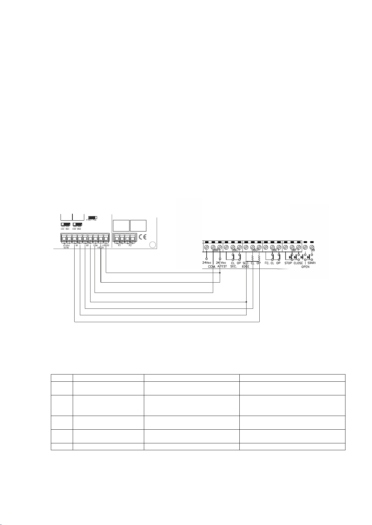
TWO SAFETY EDGES CONNECTION WITH
NEGATIVE POLARIZATION AUTOTEST
CONTROL PANEL
RBMOTION
Led
ON
OFF
Flashing
R1
Relay R1 Activation
R1 desactivated, state by default
Every 5 seconds, correct supply of the
equipment
R2/LB
Relay R2 Activation/
Indicates if the transmitter
has low battery
R2 desactivated, state by default/
Indicates if the transmitter„s battery is
working properly
Every 5 seconds, correct supply of the
equipment
B1
Relay B1 Activation or
band not connected
B1 desactivated, correct safety edge
state
B2
Relay B2 Activation or
band not connected
B2 desactivated, correct safety edge
state
CHECK
Coverage (See CHECK funcftion)
RBMOT30 / RBMOT500
INSTALLATION AND CONNECTIONS
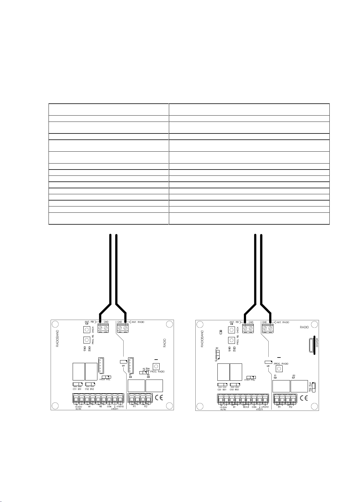
Attach the rear part of the housing to the wall using the plugs and screws supplied. Pass the cables
through the bottom of the receiver. Connect the power cables to the terminals marked in the mother
board, as indicated. Install the receiver, close to the door and avoid metal surfaces between the
receiver and the transmitter RADIOBAND. Pass the cables through the bottom of the receiver.
Program transmitters and transmitters RADIOBAND as programming section. Fix the front of the
receiver to the back with the screws supplied for the purpose.
1- Power supply 12/24V AC/DC: (+)
2- Power supply 12/24V AC/DC: (-)
3,4- R1: Connection to the safety band input of the control panel (resistive contact 8.2k) with
jumper in position BS1. Or to the control panel safety contact input (NC) with jumper in position CS1.
5,6- R2: Connection to a second safety band input of the control panel (resistive contact 8.2k) with
jumper in position BS2. Or to the control panel safety contact input (NC) with jumper in position CS2.
7- AUTOTEST: Common connection safety self-test (-). See Figure and table POLARIZED SELF-TEST.
8- AUTOTEST: Self-test connection for R1. See Figure and table POLARIZED AUTO-TEST.
9- AUTOTEST: Self-test connection for R2. See Figure and table POLARIZED AUTO-TEST.
10, 11- R1: Relay 1 output RADIO receiver
12, 13- R2: Relay 2 output RADIO receiver
LIGHT INDICATORS
Page 3

COD. 1248054-GB / 1.1
3
Configuration of transmitter programming in the receiver.
Led R1
Led R2
Standard Programming (default option,
the receiver is always configured on pluri-channel)
The relays are activated 1st relay by channel 1
and 2nd relay by channel 2 (3rd relay by channel 1
and 4th relay by channel 2)
Flashing
Flashing
Special programming
By pressing any transmitter channel,
relay 1 on the receiver will be activated
ON
OFF
By pressing any transmitter channel,
relay 2 on the receiver will be activated
OFF
ON
By pressing any transmitter channel, the two relays
will be activated at the same time*
ON
ON
In programation
Relay B1 Led
Turned on. It indicates the channel to program.
Relay B2 Led
Turned on. It indicates the channel to program.
RBMOT30 / RBMOT500
OPERATING
The pilot lights are activated every 5 seconds to indicate the correct supply of power to the
equipment.
Upon receiving a code, the receiver checks whether it is in its memory, activating the corresponding
relay R1 and/or R2. The relay activation mode is selected in either impulse or ON/OFF using the
Imp/Bies jumper (only with the relay 2). For adjustment of relay 1, see manual of the programming
tool.
The receiver checks that all the programmed bands are working properly. If a band is activated or if
there is an error in its operation, the receiver activates the appropiated B1 or B2 output relay and
the appropiated B1 or B2 light indicator turns on.
PROGRAMMING
MANUAL PROGRAMMING OF MOTION TRANSMITTERS
Press the receiver programming button for 1 sec. and an acoustic signal will be heard. The
receiver will enter standard programming (see table). If the receiver programming button is
held pressed down, the receiver Hill enter special programming, cyclically passing from one
configuration to the next. Once the programming configuration for the transmitter to be
registered has been chosen, send the code to be programmed by pressing the transmitter.
Every time a transmitter is programmed, the receiver will issue an acoustic signal for 0.5
sec.
*If working in ON/OFF activation mode, relay 1 will act as impulse and relay 2 as ON/OFF. Therefore, on the first
press relay 1 will close and open the contact and relay 2 will only close. On the second, relay 1 will close and
open the contact and relay 2 will open.
N.B.: Each transmitter can be configured independently on the receiver.
MANUAL PROGRAMMING OF RADIOBAND TRANSMITTERS
Makes it possible to store 6 RADIOBAND transmitters (3 Relay B1 and 3 on Relay B2).
Press the receiver programming PROG button for 1s; a sound signal will be heard. The
receiver will enter safety band closing programming mode (BSC). If the programming button
is kept pressed, the receiver will enter safety band opening programming mode (BSO),
moving cyclically from one really to another. Once the programming relay has been chosen
for the transmitter you want to start using, send the programming code by pressing the
RADIOBAND transmitter. Every time a transmitter is programmed, the receiver will emit a
sound signal for 0.5s.
Page 4

COD. 1248054-GB / 1.1
4
Autotest
output in
standby
Autotest
output
activated
Polarity type
Jumper ATEST
POL
ATEST1
ATEST2
Connection to an
equipment with autotest
0V
12/24V
Positive
OFF
Connected*
Connected*
12/24V
0V
inverted
ON
Connected*
Connected*
Connection to an
equipment without
autotest**
---
---
---
OFF
No
connected
No
connected
RBMOT30 / RBMOT500
Note: For proper operation of the system, the transmitter must be programmed into one
receiver only.
In both programming modes, after 10 seconds without programming, the receiver will exit
programming mode, issuing two acoustic signals of 1 sec. If upon programming a transmitter the
receiver memory is full, it will issue 7 acoustic signals of 0.5 sec. and exit programming.
RADIOBAND transmitter replacement
In case you need to replace a RADIOBAND transmitter, it is necessary to reset the system (see
TOTAL RESET on next page) and reprogram all RADIOBAND transmitters used in the installation.
TOTAL RESET
In programming mode (PROG RADIO or PROG RBAND, depending the memory which wants to be
erased), the programming button is held down and the “MR” reset jumper is bridged for 3 secs. The
receiver will issue 10 short acoustic warning signals followed by others at a faster pace to indicate
that the operation has been successful. The receiver is now in programming mode.
After 10 seconds without programming or quickly pressing the programming button, the receiver
will exit programming mode, issuing two acoustic signals of 1 sec.
OTHER RADIOBAND1G FUNCTIONS
POLARIZED AUTO-TEST
Check the auto-test output on the control panel, in standby, to see whether the voltage is
0V (inverted test input) or 12/24V AC/DC (positive polarity). The auto-test signal of the
panel must remain at its maximum for 2 seconds.
* N.B.: Only connect the auto-test output to be used.
** Where the auto-test is not used, the system is not checked at the start of the
operation, which means that security normative EN 12453 regarding the use of
motorised garage doors is, in some cases, not complied with.
SYSTEM CHECK
This function has to be used to check the operation and range of all the devices once the
installation has been carried out.
Press the receiver‟s CHECK button for at least 1 second to enter check mode. The indicator
light will come on and four beeps will be heard.
Perform a complete door opening and closing manoeuvre. During the system check a beep
will be heard every 1,5 seconds.
Page 5

COD. 1248054-GB / 1.1
5
Number of check LED flashes
Coverage
Result of check
1
Very weak
Band failure
2
Weak
OK
3
Normal
OK
4
Good
OK
5
Very good
OK
CORRECT OPERATION OF THE SYSTEM
If no other acoustic signal is heard on completing the manoeuvre, the system is operating
correctly. Either press the CHECK button again or wait 5 minutes and the RADIOBAND
receiver will exit checking automatically, indicating with two beeps that the check has been
correct. The check indicator light will go out.
DETECTION OF BAND FAILURE
If the communication with a RADIOBAND transmitter fails during checking, or the
communication is deficient (for instance, too many communication retries or poor
coverage), the RADIOBAND receiver emits three consecutive beeps, indicating that an
error has occurred. Halt the door manoeuvre and press the safety bands installed to
detect what has failed.
If a single beep is heard on pressing a band, this means that the band is correct.
If three consecutive beeps are heard on pressing the band, this means that the band has
failed.
In this event, it is recommended changing the orientation of the transmitting-receiving
aerials to ensure the desired range.
On exiting check mode, seven consecutive beeps will be heard and the indicator light will
flash continuously.
Perform another system check until the result is correct.
SIGNAL COVERAGE
After pressing one of the installed bands, continuous flashes, ranging from 1 to 5, indicate
the signal coverage for this band at the time it was pressed.
RBMOT30 / RBMOT500
TRANSMITTER BATTERY LOW INDICATOR
If the battery of a RADIOBAND transmitter programmed into the receiver becomes low, the
receiver will beep 4 times every 20 seconds. If there is more than one transmitter
programmed, each safety edge should be activated to identify, hearing the 4 beeps, which
transmitter has a low battery. If the battery power is low, replace it immediately.
In RBMOT500, you can use the second relay on the receiver as an indicator for low battery,
the output will activate when a transmitter with low battery is detected. Jumper B2/LB
must be ON for this operation.
Page 6

COD. 1248054-GB / 1.1
6
RBMOT30 / RBMOT500
OTHER MOTION FUNCTIONS
MOTION GROUPS
This equipment can work with the group identification of the system FREE. Receivers can
be configured with a group (from 0 to 7) that allows management of up to 28 doors
independently.
C=channel
G=group
N.B. Group 0 enables all groups.
GROUP CONFIGURATION
After the receiver has been totally reset, it will be configured with the group of the first
radio-programmed transmitter by enabling the hands free mode.
On powering the receiver, the led R1 will flash the same number of times as the group
number with which it is configured.
INSTALLATION ADVISES
Page 7

COD. 1248054-GB / 1.1
7
>20 cm
RBMOT30 / RBMOT500
USE OF THE EQUIPMENT
This equipment is intended to be used for remote control and be installed with a safety edge in
automatic doors installations. Their use is not guaranteed for directly activating any other equipment
different to that specified.
The manufacturer reserves the right to modify equipment specifications without prior notice.
IMPORTANT ANNEX
Disconnect the power supply before handing the unit.
In compliance with the European Directive low-voltage electrical equipment, we hereby inform users
of the following requirements:
· For units which are permanently connected, an easily accessible circuit-breaker device must be
built into the wiring system.
· This unit must always be installed in a vertical position and firmly fixed to the structure of the
building.
· This unit must only be handled by a specialised installer, by his maintenance staff or by a duly
trained operator.
· The instruction manual for this unit must always remain in the possession of the user.
· Terminals of maximum section 3,8mm2 must be used for the power supply connections.
· Use time delayed fuses.
· The two working frequencies does not interfere each other.
Hereby, JCM TECHNOLOGIES, S.A., declares that this RBMOT30, RBMOT500 is in compliance
with the essential requirements and other relevant provisions of 2004/108/CEE Directive, insofar as
the product is used correctly and 2006/95/CE low voltage directive, only if the usage is the
appropriate.
CE DECLARATION OF CONFORMITY
See web www.motion-line.com
 Loading...