

Page 1
RB3 TGL868
User’s Manual GB
Introduction
The RadioBand system is designed of domestic, commercial and industrial door applications where a safety edge is used. The system
provides a wireless system replacing spiral cables or energy chain systems to provide the safety signal to the door or gate control
panel. The receiver monitors the status of transmitters connected to it.
Up to three transmitters per output can be connected to the receiver. There are two outputs on each receiver that can be connected to
the control panel as 8k2 or NC contact.
The transmitter is compatible with 8K2 monitored safety edges or electromechanical safety edges (NC contact), and also with
standard low voltage optical safety edges and OSE-S7502 optical safety edges.
The system complies with EN ISO 13849-1, category 2, PLc.
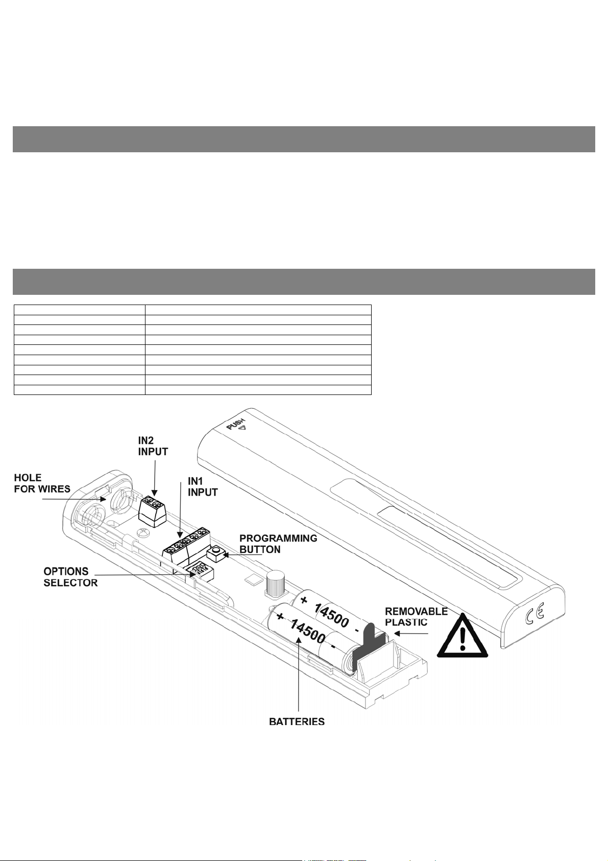
Technical data
Frequency Multifrequency system 868MHz auto-adjustable
Power supply 3,6V DC (2 x 3,6V LS14500 Li-SOCl2)
Operating consumption 12mA
Radiated power < 25mW
Operating temperature -20ºC - +85ºC
Watertighness IP22
Size 40 x 194,5 x 20mm
Range 100m
Battery life (aprox) 2 Years
1246078_Rev1.1RB3TGL868 Page1/4
Page 2
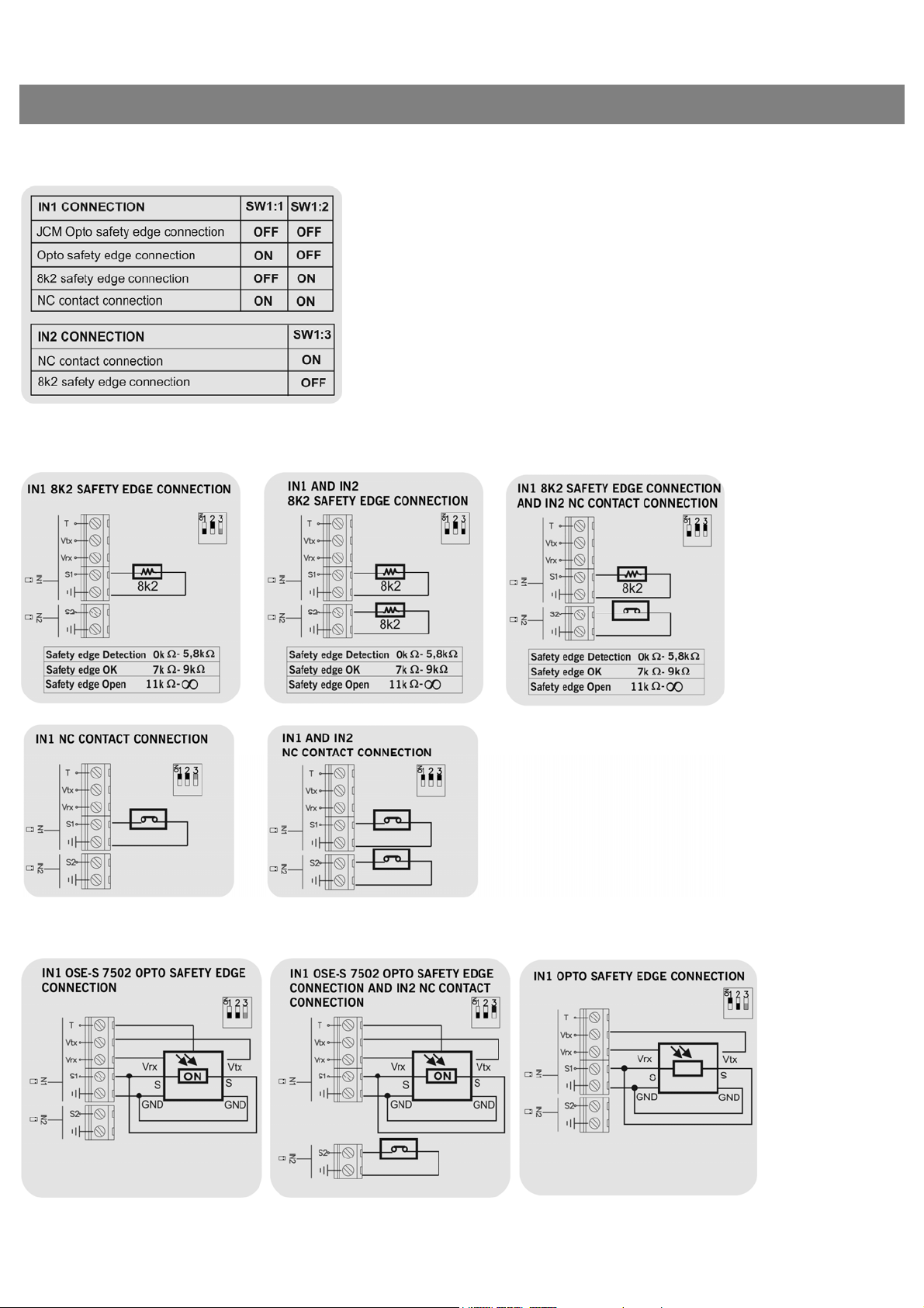
Connection
Option Selector
Examples of connection of 8k2safety edges or NC contact
Examples of connection of different types of opto safety edges
1246078_Rev1.1RB3TGL868 Page2/4
Page 3

Starting up
Installation
SWIPE TO OPEN COVER DRILL DOOR SEE CONNECTION CLAUSE REMOVE PLASTIC
SEE PROGRAMMING CLAUSE SEE CHECK CLAUSE SWIPE TO CLOSE COVER
Programming transmitter to receiver
The receiver allows programming 6 transmitters (3 for Relay 1 and 3 for Relay 2). Each safety edge transmitter must be learnt into the
appropriate channel of the safety edge receiver. A transmitter should only be connected to one receiver.
Press PROG button and keep pressed until desired mode selected.
Programming of one safety transmitter (IN1 input)
Mode Configuration of transmitter programming in the receiver. Led R1 Led R2
1 Safety edge activates relay 1 on the receiver ON OFF
2 Safety edge activates relay 2 on the receiver OFF ON
3 Safety edge activates the two relays 1 and 2 at the same time
Programming of two safety transmitters (IN1 and IN2 input)
Mode Configuration of transmitter programming in the receiver. Led R1 Led R2
4 Safety edge in IN1 activates relay 1 and safety edge in IN2 activates relay 2
PRESS RPROG PUSHBUTTON LED TURNS ON PRESS TRANSMITTER PROG ONE BEEP & PROGRAMMED
ON ON
Flashing Flashing
PRESS RPROG PUSHBUTTON LED TURNS OFF & END PROG
Check the correct operation
Press each safety edge connected to assure that the appropriate relay on the receiver is activated.
If not, see the Leds and Beeps indication table, to check what is happening and how to solve it.
1246078_Rev1.1RB3TGL868 Page3/4
Page 4

Maintenance
Leds and beeps indication table
The status of leds is shown during 5 minutes after pressing PROG button or during the Check function. The rest of the time they are
turned off.
IN1 / IN2
Led status
OFF No beeps RB3
ON No beeps RB3
Intermittent No beeps RB3
OFF 4 beeps every
ON No beeps RB3 receiver Communication failure between RB3 R and RB3 T Verify the radio signal with the Check function.
Replacing the transmitter battery
Remove the box cover. Replace the two used batteries with new ones, taking into account the polarity indicated by the connector.
Check that the new batteries support the same temperature range as those they are replacing.
Use of the system
This equipment is designed to be installed with a safety edge for door and gate installations. It is not guaranteed for directly
activating equipment other than that specified.
The manufacturer reserves the right to change the specification of the equipment without prior warning.
Important Annex
Disconnect the power supply whenever you proceed to the installation or repair of the control panel.
In accordance with the European low voltage directive, you are informed of the following requirements:
· For permanently connected equipment, an easily accessible connection device must be incorporated into the cabling.
· This system must only be installed by a qualified person that has experience with automatic doors/gates and knowledge of the
relevant EU standards.
· The instructions for use of this equipment must always remain in the possession of the user.
· Terminals with a maximum section of 3.8mm2 must be used to connect the cables.
· The frequency of the RadioBand system does not interfere in any way with the 868 MHz remote control systems.
JCM TECHNOLOGIES, S.A. declares herewith that the product RB3 TGL868 complies with the requirements of the 1999/5/ CEE
R&TTE Directive, and complies with the fundamental requirements of the 2006/42/CE Machine Directive, 2004/108/EC Directive
on electromagnetic compatibility and 2006/95/EC on low voltage, insofar as the product is used correctly.
EC Declaration of conformity
See web www.jcm-tech.com
Beeps Equipment Message / error
transmitter
transmitter
transmitter
RB3 receiver RB3 transmitter low battery Verify the batteries of the transmitter
20 seconds
Safety edge connection and operating correctly ---
Safety edge detected ---
The safety edge does not operates well (it is not
connected or not programmed)
Solution
Connect properly or program the safety edge transmitter
on the receiver.
1246078_Rev1.1RB3TGL868 Page4/4
 Loading...