

Page 1
1222059-GB/1.2
1
Page 2

1222059-GB/1.2
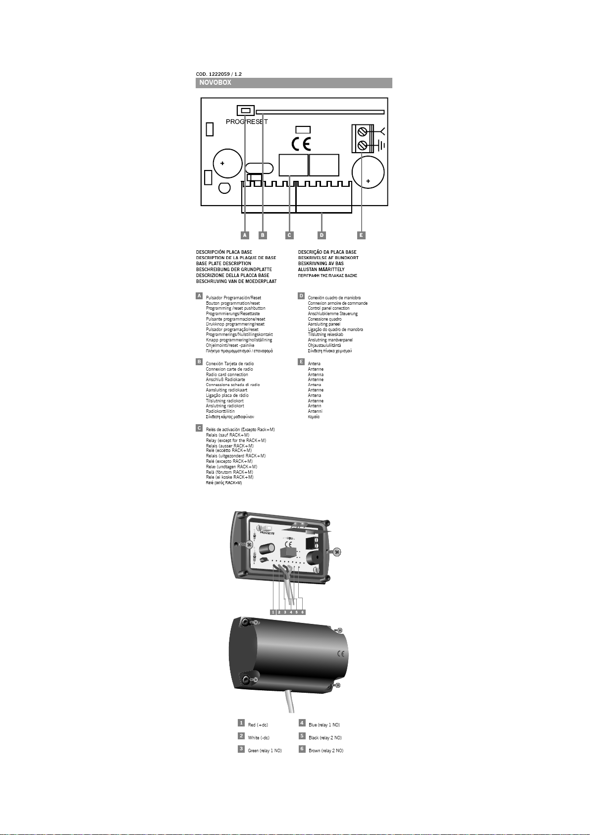
RECEIVERS DCS RACK+M - RACK+M1C/2C - NOVOBOX1/2
GENERAL DATA / TECHNICAL DATA
RACK+M RACK+M1C/2C NOVOBOX1/2
Frequency 433,92MHz /
868,35MHz
Code memorisation Self-learning Self-learning Self-learning
Memory Permanent EEPROM 31
cod.
N. of channels 1 1 or 2 1 or 2
Antenna Built-in Built-in Built-in
Power supply 12 / 24 V ac. dc. 12 / 24 V ac. dc. 12 / 24 V ac. dc.
range in 12V dc from 11,8V to 13V --- --Relay contacts 1 A / 125 V ac. 1 A / 125 V ac. 1 A / 125 V ac.
Sensitivity > -100 dBm > -100 dBm > -100 dBm
Consumption rest 19 mA 15 mA 15 mA
Max consumption 107 mA 75mA 75mA
Working temp - 20 to + 85º C - 20 to + 85º C - 20 to + 85º C
Watertight --- --- IP44
Mother board dimensions 67x41x24 mm 67x41x24 mm 67x41x24 mm
Dimensions --- --- 98x58x40 mm
OPERATION
Upon receiving a code, the receiver first checks whether it is stored in memory and then
activates the output
OPERATING MODE “SINGLE CHANNEL OR MULTIPLE CHANNEL”
• Single channel: the relay can be activated by the 1rst or 2ond, 3rd or 4th channel of a
transmitter already stored in the receiver.
• Multiple channel: the relays are activated as follows, 1rst channel by the relay 1, and
2ond by the relay 2 (if they exists).
INSTALLATION AND CONNECTIONS
Disconnect the power before working on the receiving installation.
CHASSIS ATTACHMENT
Attach the rear part of the chassis to the wall using the plugs and screws supplied. Mount
the receiver front and pass the cables and the antenna through it. Do not position the
receiver less than 5 metres away from another receiver and/or active antenna.
CONNECTIONS
Connect the power cables to the terminals marked 1(+dc) and 2(-dc) in the mother board,
as indicated.
PROGRAMMING
MANUAL PROGRAMMING
Press the programming pushbutton; a red programming led will turn in and a long acoustic
signal Will sound. Then send the code(s) to be programmed, pressing the transmitter. A
short audible signal will sound after each code is memorised. If no new transmitter is
recorded in a space of 10 seconds or by pressing the button in the rear of one of the
recorded transmitters, the receiver leaves the programming mode.
433,92MHz /
868,35MHz
Permanent EEPROM 31
cod.
433,92MHz
Permanent EEPROM 31
cod.
2
Page 3

1222059-GB/1.2
PROGRAMMING VIA ADDITIONAL RADIO TRANSMITTERS WITH “MASTER
TRANSMITTER”
It is necessary to have a transmitter already recorded in this receiver. Press the button in
the rear of the transmitter which is already recorded in this receiver (if there is more than
one receiver nearby, this will activate the programming mode in all the receivers). The
receiver will emit a long acoustic signal, indicating it has entered the programming mode.
To record each of the new transmitters, press the corresponding channel in each of them.
A short acoustic signal after each recording will confirm that the programming has
proceeded correctly. If no new transmitter is recorded in a space of 10 seconds or by
pressing the button in the rear of one of the recorded transmitters, the receiver leaves the
programming mode.
PROGRAMMING VÍA ADDITIONAL RADIO TRANSMITTERS WITHOUT “MASTER
TRANSMITTER” (PIN-MODE)
In order to operate in this mode, it is necessary to first insert an installation “PIN”. This
“PIN” is a four-digit number, which is inserted, by means of a MANAGER+DCS or
MINIMAN+DCS, into the first transmitter which is recorded in the receiver. To record the
“PIN” into the receiver, press the programming pushbutton during 1s, a long acoustic
signal will indicate it has entered the programming mode. Continue pressing during 4s
more, and a long intermittent acoustic signal will indicate that the memory has been
erased. Continue pressing the pushbutton and now you can press the transmitter. Then,
two short acoustic signals will indicate the exit of the programming mode. As from now,
the receiver will recognize this “PIN” in any transmitter inserted. This “PIN” will be emitted
pressing the pushbutton of the rear part of the respective transmitter, and automatically,
the receiver will store it in his memory with a long acoustic signal.
DELETION OF MEMORY
A code cannot be deleted individually. It can only be eliminated by performing a “system
reset”. To erase the memory, press the programming button for 5 seconds. A long “beep”
will indicate that the unit has entered the programming mode. After the 5 seconds, the
unit will emit a series of intermittent “beeps”, indicating that the memory is free and that
the receiver is in the programming mode. The installation PIN will remain operative, in
case you are using PIN-MODE.
Note: in the hypothetical event of the receiver memory being affected by some unusual
external factor, the unit will emit an intermittent acoustic signal when the transmitter is
pressed.
CODE REPLACEMENT
This function enables you to cancel transmitter without the necessity of having the receiver
present. By means of a MANAGER+DCS or MINIMAN+DCS and knowing the code, you
can change the “Replacement Number”, from “0” to “7” for transmitters (0 is the first
remote control delivered by the factory, and 7 the last “replacement” before setting the
code as obsolete in the installation). The system permits such “replacements” from a new
transmitter, changing the code and “Replacement Number” (see MANAGER+DCS portable
programmer manual). Emitting the code to the receiver, the new replacement number will
cancel the previous one and will be automatically updated. In the installation, the user
must activate the transmitter twice. The first time, the receiver updates the new element
and cancels the previous one. The second time, the receiver activates the corresponding
operation in the receiver.
3
Page 4

1222059-GB/1.2
USING THE RECEIVER CARD
This receivers are designed for the remote control of garage doors, to send the activation
commands to control panels in which the card is inserted. Its use is not guaranteed for
directly activating units other than those specified. The manufacturer reserves the right to
modify the equipment specifications without notification.
IMPORTANT ANNEX
In compliance with the European Directive low-voltage electrical equipment, we hereby
inform users of the following requirements: for units which are permanently connected, an
easily accessible circuitbreaker device must be built into the wiring system; this unit must
always be installed in a vertical position and firmly fixed to the structure of the building;
this unit must only be handled by a specialised installer, by his maintenance staff or by a
duly trained operator; the instruction manual for this unit must always remain in the
possession of the user.
EC DECLARATION OF CONFORMITY
The manufacturer
JCM TECHNOLOGIES, S.A.
C/Bisbe Morgades, 46 Baixos
08500 VIC – Barcelona
SPAIN
declares herewith that the product designated below complies with the relevant
fundamental requeriments as per Article 3 of the R&TTE Directive 1999/5/EG, insofar as
the product is used correctly, and that the following standards apply:
Product: Receiver 433,92MHz / 868,35MHz
Manufactured by: JCM TECHNOLOGIES, S.A.
Trade mark: JCM
Type: RACK+M, RACK+M1C/2C, NOVOBOX1/2
Environment of use: Residential, commercial and light industry
Standards:
• Telecommunication EN 300 220-1 v1.3.1 (2000-09), EN 300 200-3 v1.1.1 (2000-
09)
• Electromagnetic Compatibility EN 301 489-3 v1.3.1 (2001-11), EN 301 489-1 v1.3.1
(2001-09)
• Low Voltage EN 60730-1 (2000)
Vic, 03/01/03
JUAN CAPDEVILA MAS
General manager
4
 Loading...