

Page 1

GENERAL INDEX
1. Introduction ........................................................................................................3
1.1 General considerations ..............................................................................5
1.2 Descriptive diagram MANAGER+DCS.......................................................6
1.3 Descriptive diagram of the Proximity key...................................................7
1.3.1 Technical characteristics .............................................................7
1.3.2 Diagram connection.....................................................................7
1.4 Menu Tree..................................................................................................8
2. Quick guide for the maintenance of installations .........................................11
2.1 Retrieving an installation..........................................................................13
2.2 Modifying the code of a transmitter, smartcard or proximity key..............13
2.3 Creating a new code ................................................................................14
2.4 Deleting a code ........................................................................................14
2.5 Reading “n” transmitters...........................................................................14
2.6 Storing “n” transmitters.............................................................................15
2.7 Reading “n” smartcards............................................................................16
2.8 Storing “n” smartcards..............................................................................18
2.9 Reading "n" proximity keys ......................................................................19
2.10 Storing "n" proximity keys ........................................................................20
2.11 Entering reserve codes ............................................................................21
2.12 Changing the installation channel ............................................................22
3. Creating installations.......................................................................................25
3.1 Creating the installation in the Portable Programmer
and storing it in the receiver unit ..............................................................27
1.3.3 Using the code of the transmitter /
smartcard / proximity key ...........................................................27
Installing a Receiver .............................................................................28
Installing a Mini-A.C. Unit......................................................................
Installing a Maxi-A.C. Unit.....................................................................
30
33
1.3.4 Generating the code of the transmitter in the
Portable Programmer and storing it in the transmitter ...............37
Installing a Receiver, Mini-A.C. Unit or Maxi-A.C. Unit..........................37
3.2 Creating the installation in the receiver unit and storing it
in the Portable Programmer (Recommended option) ..............................40
Installing a Receiver .............................................................................40
Installing a Mini-A.C. Unit......................................................................
Installing a Maxi-A.C. Unit.....................................................................
42
43
4. Connection to PC .............................................................................................45
4.1 Connection software ................................................................................47
4.1.1 Minimum requirements of the PC...............................................47
4.2 Connection system...................................................................................47
5. General functions.............................................................................................49
5.1 Remarks...................................................................................................51
5.2 Read Transmitter Menu ...........................................................................51
5.3 Read Smartcard Menu .............................................................................51
Page 2

5.4 Read Proximity Key Menu........................................................................52
5.5 Memorize Transmitter Menu ....................................................................52
5.6 Memorize Smartcard Menu......................................................................52
5.7 Memorize Proximity Key Menu.................................................................53
5.8 Copy Transmitter Menu............................................................................53
5.9 Transmitter Replacement Menu...............................................................53
5.10 Replace Smartcard Menu ........................................................................54
5.11 Replace Proximity Key Menu ..................................................................55
5.12 Direct functions for reading or storing a transmitter,
smartcard or proximity key.......................................................................55
5.12.1 Reading transmitter....................................................................56
5.12.2 Read smartcard .........................................................................56
5.12.3 Read proximity key.....................................................................56
5.12.4 Memorize transmitter .................................................................56
5.12.5 Memorize smartcard ..................................................................56
5.12.6 Memorize proximity key .............................................................56
5.13 Create a Receiver, Mini-A.C. or Maxi-A.C. installation.............................56
5.13.1 Modify a code.............................................................................57
5.13.2 Create a new code.....................................................................57
5.13.3 Delete a code.............................................................................57
5.13.4 Change the password of a Mini-A.C. or Maxi-A.C.
installation created with the MANAGER+DCS...........................57
5.13.5 Go to position.............................................................................57
5.13.5 Memorize “n” transmitters/Memorize “n” smartcards/
Memorize “n” keys......................................................................57
5.13.7 Read “n” transmitters/Read “n” smartcards/Read “n” keys ........58
5.13.8 Change status............................................................................58
5.13.9 New installation..........................................................................58
5.13.10 Reserve codes ...........................................................................59
5.13.11 Change channel.........................................................................59
To change the channel individually to a position ...................................59
To change the channel to a complete installation .................................
5.13.12 Configure codes in zonal mode .................................................59
5.14 Read installation memory card.................................................................60
5.15 Programming installation memory card....................................................60
5.16 Save installation in memory cartridge ......................................................61
5.17 Restore installation from memory cartridge .............................................61
5.18 Change type of memory card...................................................................62
5.19 Protect access to memory........................................................................63
5.20 Program a memory card in old/new format..............................................63
5.21 Add installation PIN .................................................................................63
5.21.1 Enter installation PIN in a TM126 or TM500 ..............................63
5.21.2 Enter installation PIN in Transmitters.........................................64
5.22 Delete installation from memory cartridge................................................64
5.23 Delete memory cartridge..........................................................................65
5.24 Change password for access to MANAGER+DCS ..................................65
5.25 Change language.....................................................................................65
5.26 Save configuration ...................................................................................66
59
Page 3

1. Introduction
1.1 General considerations
1.2 Descriptive diagram MANAGER+DCS
1.3 Descriptive diagram of the Proximity key Interface
1.3.1 Technical characteristics
1.3.2 Diagram connection
1.4 Menu Tree
Page 4

NOTES
Page 5

Introduction
The MANAGER+DCS Portable Programmer allows the complete management of
installations, programming of transmitters, receiver or Access Control memories
and direct programming of smartcards and proximity keys. It is a powerful tool for
the installer.
It can incorporate a secret installer code, transferable to the whole system, which
prevents intrusion and creates customer loyalty. It also includes a password which
the installer can change at will and which protects the system in the event of unauthorised handling.
It operates by way of a rotary menu and with fixed function keys, which make it
possible to read transmitter, smartcard codes and proximity keys, read receiver and
Access Control memories, store codes individually or in groups, generate reserve
codes, etc. All of the information can be saved in memory cartridges or transmitted
to a computer and stored on diskettes.
It has a numerical keyboard, an LCD screen, low consumption (1.5V batteries or
mains power unit), and an automatic switch-off function for battery saving.
1.1 General considerations
Ensure that the receiver device is switched off at the mains before performing any operation with the memory elements.
If working simultaneously with transmitters, smartcards and proximity keys,
avoid having them inserted in the Portable Programmer at the same time. This could
cause errors.
In order to work with the Portable Programmer, a memory cartridge must be inserted (see figure on page 6, no. 12).
If an erroneous password is entered three times in succession, the Portable Programmer is deactivated. To reactivate it, leave it switched on for two minutes, after
whichtime it will emit a series of “beeps” and then request the password again.
The Portable Programmer always works in its internal memory. This means that
whenever any operation is performed with it, the results must always be saved in
the memory cartridge of the receiver, as otherwise all of the information would be
lost on switching off the programmer.
The autonomy period of the programmer on battery power is approximately 30
hours. When the battery level is low, the “low power” LED will light up (see figure
on page 6, no. 7), and the message “low battery” will appear on the screen. We
recommend replacing the batteries at this moment, as otherwise the MANAGER+DCS could induce errors.
The Portable Programmer has an automatic switch-off function: if no operation is
performed for five minutes, it will emit a series of “beeps” before switching off
automatically. While it is emitting this warning, if any key is pressed, it will return to
the normal “on” state.
5
Page 6
MANAGER+DCS 3.0X I
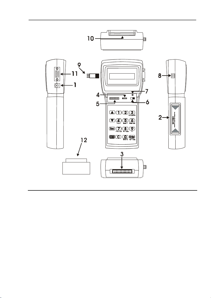
1.2 Descriptive diagram MANAGER+DCS
1. External power supply 9V –DC (the interior pin is the negative)
2. Battery housing 4 x 1.5V
3. Installation memory cartridge connector
4. Receiver and Mini-A.C. memory card connection
5. Maxi-A.C. memory card connection
6. Power switch
7. Low power indicator LED
8. Transmitter connection
9. Transmitter connection adapter
10. Smartcard connection
11. RS-232 connection to PC
12. Portable Programmer memory cartridge
6
Page 7
Introduction
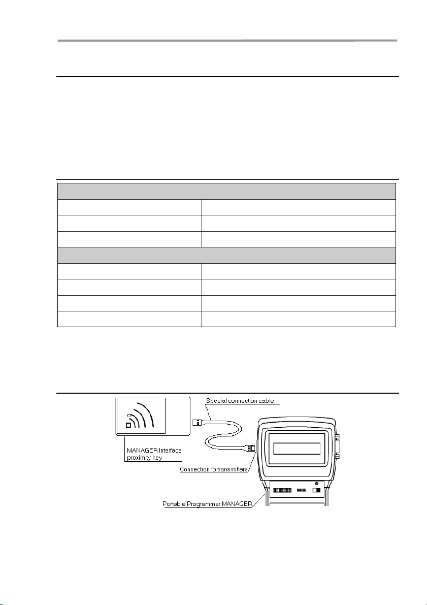
1.3 Descriptive diagram of the Proximity Key Interface
The proximity system allows the transmission of data between the MANAGER+DCS
Interface and the proximity key to take place with no physical contact: simply place
the key some 4 cm. from the Interface zone indicated with a serigraph.
Each proximity key has a personal code, which can be reprogrammed by using a
Portable Programmer MANAGER+DCS. The key is highly attractive, very small and
can be carried as a key ring. In addition, it is very inexpensive to maintain and does
not use batteries.
1.3.1 Technical characteristics
General Data
Reading system By proximity
Working distance 4 cm.
Housing Plastic
Technical Data
Power supply Via the Portable Programmer MANAGER+DCS(*)
Idle/working consumption 12 / 53 mA
Oscillation frequency 125 Khz
Working temperature range -20 ºC to + 55 ºC
(*) Owing to the Interface’s high consumption, we recommend that if extensive work
is needed with it, connect the MANAGER+DCS to the mains supply so as to avoid
shortening battery life.
1.3.2 Diagram connection
Insert one end of the special connection cable in the connection slot of the
MANAGER+DCS Proximity Key Interface, and the other in the connection for transmitters
of the Portable Programmer MANAGER+DCS (see figure page 6, no. 8 of the
MANAGER+DCS manual).
7
Page 8
g
g
g
g
g
g
g
MANAGER+DCS 3.0X I
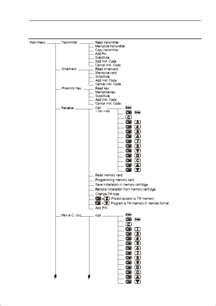
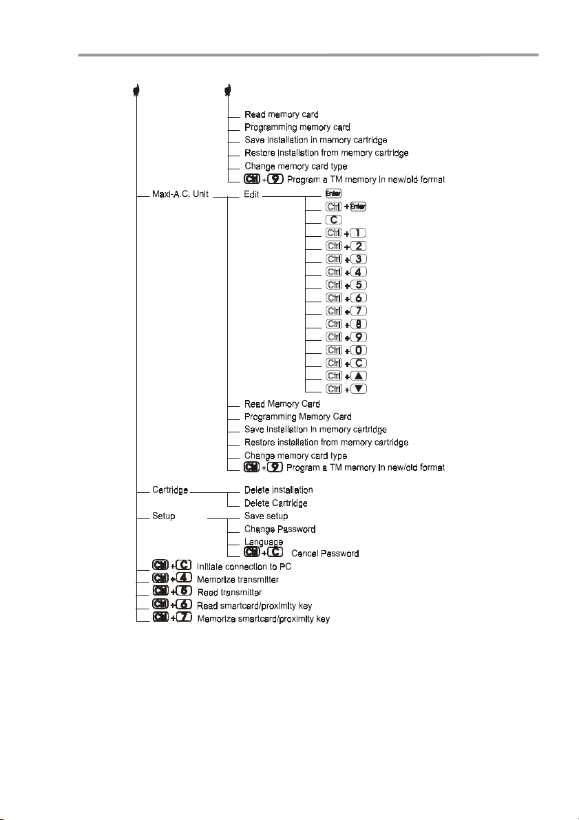
1.4 Menu Tree
Modify code
+
New code
Delete code
+
+
+
+
+
+
+
+
+
+
+
e position
Chan
Memorize "n" transmitters
Read "n" transm itters
Read "n" sm artcards or prox. keys
Mem orize "n" smartcards or prox. keys
Chan
e status R/G
New installation
Reserve codes
e installation channel
Chan
Increase channel position
Decrease channel position
Modify code
+
New code
Delete code
+
+
+
+
+
+
+
+
+
+
+
+
8
e password
Chan
Chan
e position
Memorize "n" transmitters
Read "n" transm itters
Read "n" sm artcards or prox. keys
Mem orize "n" smartcards or prox. keys
e R/G status
Chan
New installation
Reserve codes
e installation channel
Chan
Increase channel position
Decrease channel position
Page 9
MenuMenu
Introduction
Modify code
New code
Delete code
Change password
Configure chan nelszonal mode
Change position
M em orize "n" transm itte rs
Re ad "n" trans mitters
Read "n" smartcards or prox. keys
Memorize "n" smartcards or prox. keys
Change status R/G
New installation
Reserve codes
Change installation channel
Increase chan nel position
Decrease channel position
9
Page 10

MANAGER+DCS 3.0X I
NOTES
10
Page 11

2. Quick guide for the maintenance
of installations
2.1 Retrieving an installation
2.2 Modifying the code of a transmitter, smartcard or
proximity key
2.3 Creating a new code
2.4 Deleting a code
2.5 Reading “n” transmitters
2.6 Memorizing “n” transmitters
2.7 Reading “n” smartcards
2.8 Memorizing “n” smartcards
2.9 Reading “n” proximity keys
2.10 Memorizing “n” proximity keys
2.11 Entering reserve codes
2.12 Changing the installation channel
Page 12

NOTES
Page 13
Quick guide for the maintenance of installations
The maintenance of an existing installation can include various operations, such as
enlarging the number of codes, changing one or more code numbers, cancelling
code numbers, and so on. To carry out this maintenance, the first and obligatory
step to be taken is the retrieval of the installation.
2.1 Retrieving an installation
Insert the Receiver memory card in the slot (see figure on page 6, nos. 4 or 5), or
the memory cartridge where the installation is stored. The following example is for
a Single-Channel Receiver memory card.
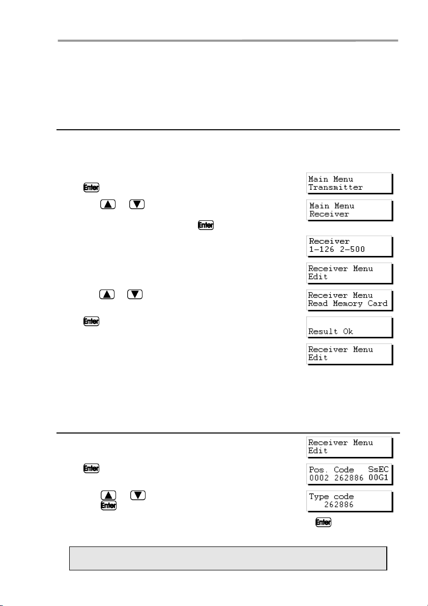
Connect the Portable Programmer and enter the password.
Press
Using the or keys, locate the menu corresponding
to the receiver device being used, that is, Receiver, MiniA.C. Unit or Maxi-A.C. Unit. Press
The following menu will appear on the screen:
Press 1 or 2 depending on the type of memory to be used,
and the following screen will immediately appear.
Using the or keys, go to menu:
Press .
The following menu will reappear on the screen:
The installation is now stored in the internal memory of the Portable Programmer
and can therefore be handled.
. The following menu will appear on the screen:
.
2.2 Modifying the code of a transmitter, smartcard or
proximity key
From the menu:
Press . The installation will appear on the screen:
Using the or keys, select the code to be modified
and press
Enter the new code by means of the numerical keys and press . The new code
will appear on the screen. The new code will be in the reserve state (R).
Remember to store the installation again in the memory card and in the
memory cartridge in order to make the changes effective.
13
.
Page 14
MANAGER+DCS 3.0X I
2.3 Creating a new code
Retrieve the installation as indicated in section 2.1 of this chapter.
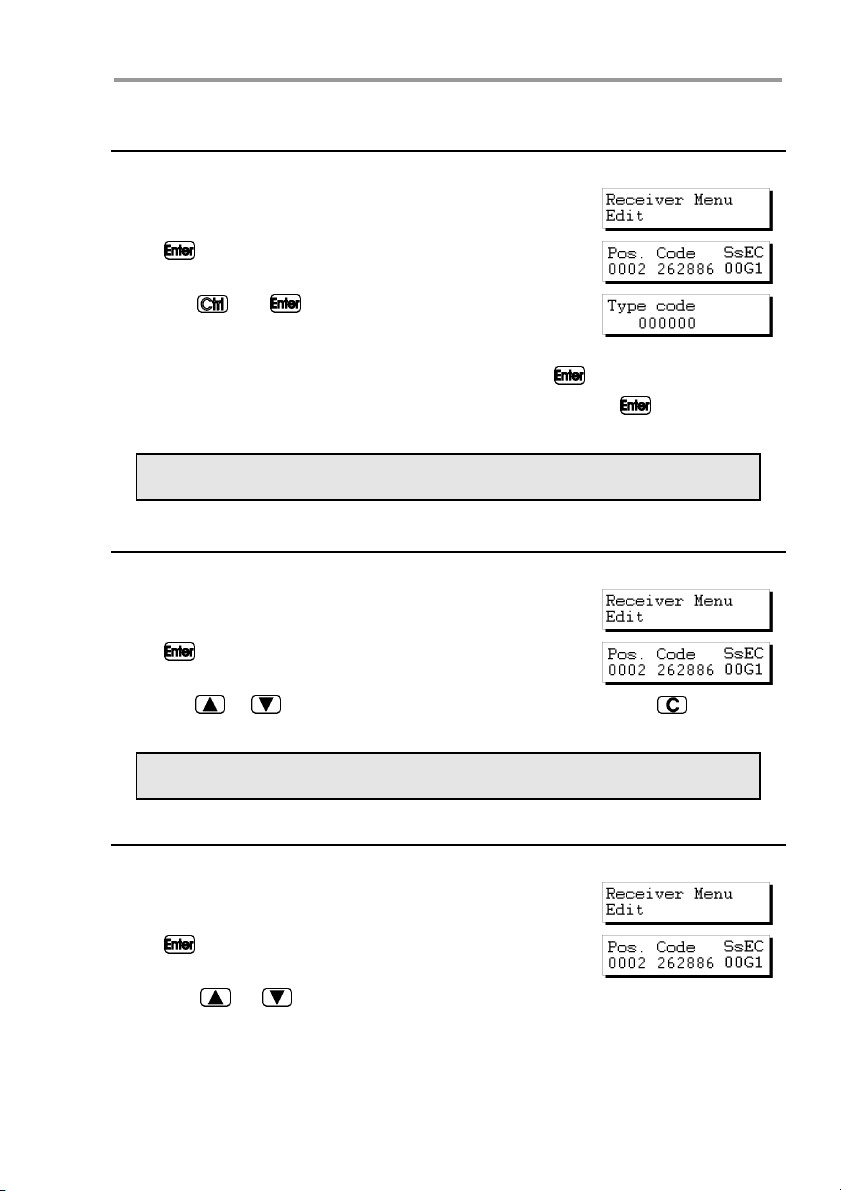
From the menu:
Press . The installation will appear on the screen:
Press the and
message will appear on the screen:
In the case of a Mini-A.C. or Maxi-A.C., enter the position
from which you wish to create the new code and press
Enter the new code by means of the numerical keys and press
will appear on the screen. The new code will be in the reserve state (R).
Remember to store the installation again in the memory card and in the
memory cartridge in order to make the changes effective.
keys simultaneously. The following
. The new code
2.4 Deleting a code
Retrieve the installation as indicated in section 2.1 of this chapter.
From the menu:
Press . The installation will appear on the screen:
Using the or keys, select the code to be deleted and press . The code
number will have been deleted.
Remember to store the installation again in the memory card and in the
memory cartridge in order to make the changes effective.
2.5 Reading “n” transmitters
Retrieve the installation as indicated in section 2.1 of this chapter.
From the menu:
Press . The installation will appear on the screen:
Using the or keys, enter the position from which you wish to read the
transmitters.
14
Page 15
Quick guide for the maintenance of installations
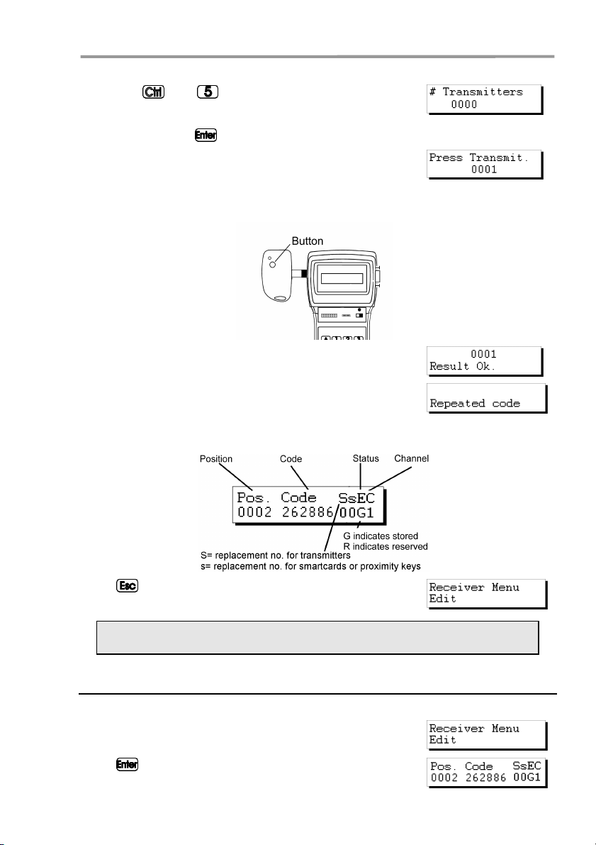
Press the and keys simultaneously. A message
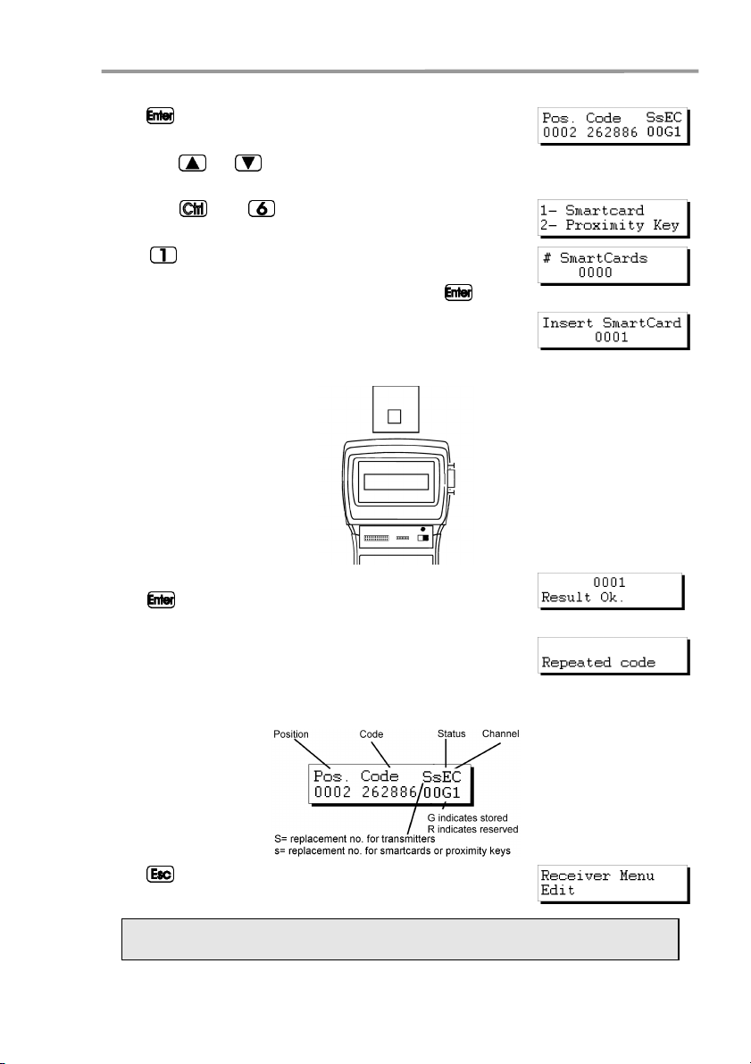
will appear on the screen requesting the number of transmitters to be read. Enter the quantity by means of the numerical keys. Press
The following message will appear:
Insert the transmitter into the transmitter connection adapter (see figure on page
6, no. 9) and press any button of the transmitter.
The confirmation of the operation will appear on the screen:
If we try to enter a transmitter twice, the following message
will appear:
Once all of the transmitters have been entered, the screen will show the position of
each transmitter, the code, the replacement number, the status and the channel.
.
Press to return to the menu.
Remember to store the installation again in the memory card and in the
memory cartridge in order to make the changes effective.
2.6 Storing “n” transmitters
Retrieve the installation as indicated in section 2.1 of this chapter.
From the menu:
Press
. The installation will appear on the screen:
15
Page 16
MANAGER+DCS 3.0X I
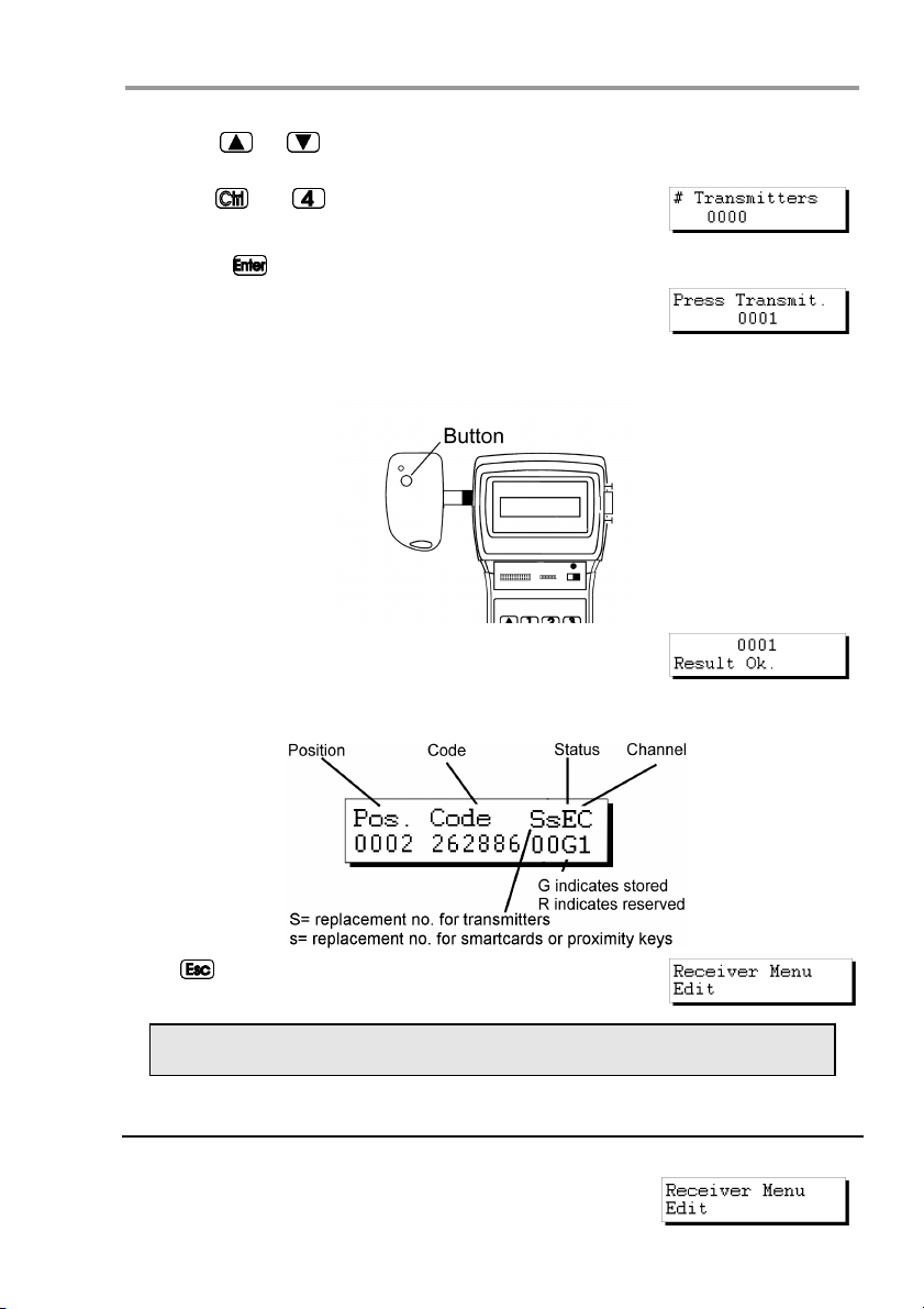
Using the or keys, enter the position from which you wish to store the
transmitters.
Press the
appear on the screen requesting the number of transmitters
to be stored. Enter the quantity by means of the numerical
keys. Press
The following message will appear:
Insert the transmitter into the transmitter connection adapter (see figure on page
6, no. 9) and press any button of the transmitter.
The confirmation of the operation will appear on the screen:
Once all of the transmitters have been entered, the screen will show the position of
each transmitter, the code, the replacement number, the status and the channel.
and keys simultaneously. A message will
.
Press to return to the menu:
Remember to store the installation again in the memory card and in the
memory cartridge in order to make the changes effective.
2.7 Reading “n” smartcards
Retrieve the installation as indicated in section 2.1 of this chapter.
From the menu:
16
Page 17
Quick guide for the maintenance of installations
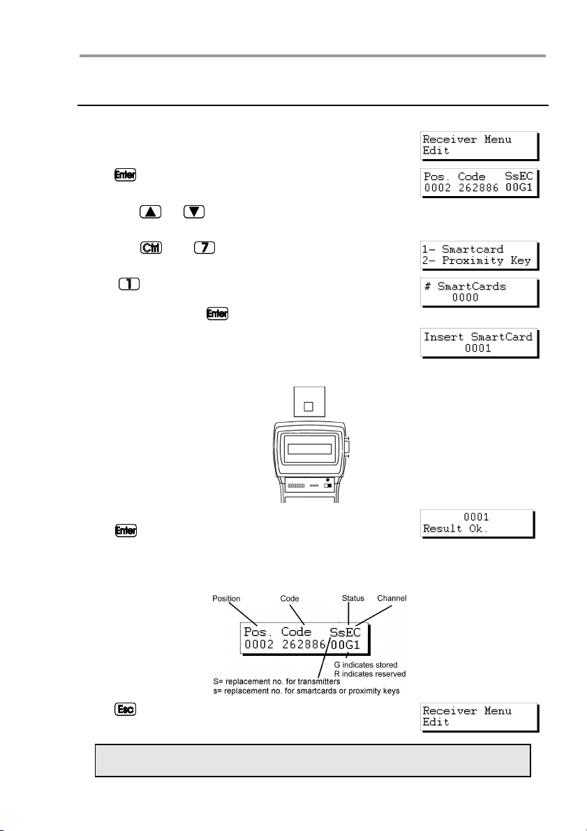
Press . The installation will appear on the screen:
Using the or keys, enter the position from which you wish to read the
smartcards.
Press the
will show:
Press
questing the number of smartcards to be read. Enter the
quantity by means of the numerical keys. Press
The following message will appear:
Insert the card into the smartcard connector (see figure on page 6, no. 10).
and keys simultaneously. The screen
and a message will appear on the screen re-
.
The confirmation of the operation will appear on the screen.
Press
another smartcard.
If we try to enter a transmitter twice, the following message
will appear:
Once all of the smartcards have been entered, the screen will show the position of
each card, the code, the replacement number, the status and the channel.
Press to return to the menu:
for the programme to request the introduction of
Remember to store the installation again in the memory card and in the
memory cartridge in order to make the changes effective.
17
Page 18
MANAGER+DCS 3.0X I
2.8 Storing “n” smartcards
Retrieve the installation as indicated in section 2.1 of this chapter.
From the menu:
Press . The installation will appear on the screen:
Using the or keys, enter the position from which you wish to read the
smartcards.
Press the
will show:
Press
smartcards you wish to save. Enter the quantity using the
numerical keys. Press
The following message will appear:
Insert the card into the smartcard connector (see figure on page 6, no. 10).
and keys simultaneously. The screen
and a message will ask for the number of
.
The confirmation of the operation will appear on the screen.
Press
another smartcard.
Once all of the smartcards have been entered, the screen will show the position of
each card, the code, the replacement number, the status and the channel.
Press
for the programme to request the introduction of
to return to the menu:
Remember to store the installation again in the memory card and in the
memory cartridge in order to make the changes effective.
18
Page 19
Quick guide for the maintenance of installations
2.9 Reading “n” proximity keys
Retrieve the installation as indicated in section 2.1 of this chapter.
From the menu:
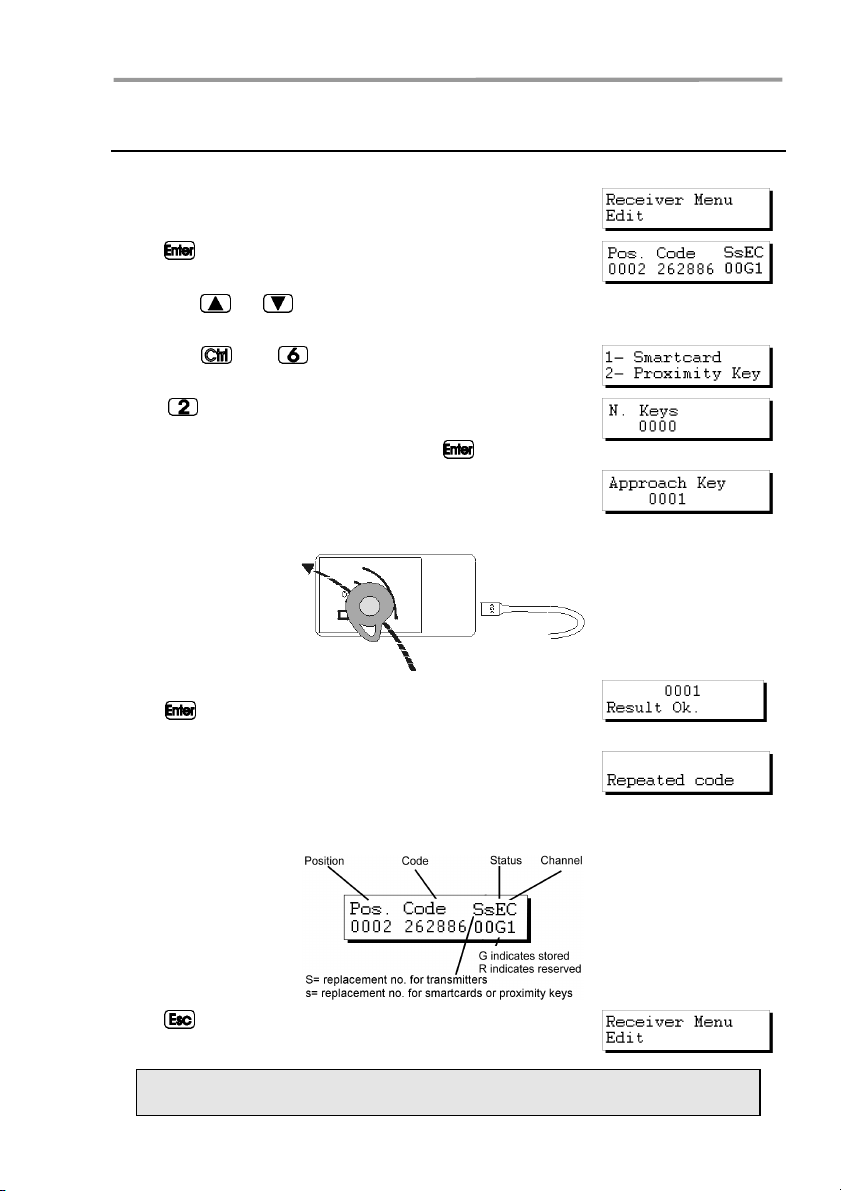
Press . The installation will appear on the screen:
Using the or keys, enter the position from which you wish to read the
proximity keys.
Press the
will show:
Press
questing the number of proximity keys to be read. Enter the
quantity using the numerical keys. Press
The following message will appear:
Approach the key to the Proximity Key Interface.
and keys simultaneously. The screen
and a message will appear on the screen re-
.
The confirmation of the operation will appear on the screen.
Press
another proximity key..
If we try to enter a proximity key twice, the following message will appear:
Once all of the keys have been entered, the screen will show the position of each
card, the code, the replacement number, the status and the channel.
Press
for the programme to request the introduction of
to return to the menu:
Remember to store the installation again in the memory card and in the
memory cartridge in order to make the changes effective.
19
Page 20

MANAGER+DCS 3.0X I
2.10 Storing “n” smartcards
Retrieve the installation as indicated in section 2.1 of this chapter.
From the menu:
Press . The installation will appear on the screen:
Using the or keys, enter the position from which you wish to read the
proximity keys.
Press the
will show:
Press
keys you wish to store. Enter the quantity using the numerical keys. Press
The following message will appear:
Approach the key to the Proximity Key Interface.
and keys simultaneously. The screen
and a message will ask how many proximity
.
The confirmation of the operation will appear on the screen.
Press
another proximity key.
Once all of the keys have been entered, the screen will show the position of each
card, the code, the replacement number, the status and the channel.
Press to return to the menu:
for the programme to request the introduction of
Remember to store the installation again in the memory card and in the
memory cartridge in order to make the changes effective.
20
Page 21

Quick guide for the maintenance of installations
2.11 Entering reserve codes
Retrieve the installation as indicated in section 2.1 of this chapter.
From the menu:
Press . The installation will appear on the screen:
Using the or keys, enter the position from which you wish to read the
smartcards.
Press the
appear on the screen of the Portable Programmer asking
how many codes are to be reserved and in what manner,
sequentially or at random.
If you press
available that are not reserved and will ask how many codes
you wish to reserve. Enter the quantity by means of the numerical keys and press
It will then ask which channel is to be used.
If you wish to create a Mini-A.C. or Maxi-A.C. installation,
see the section on “Reserve Codes” in chapter 5 (General
functions).
Select the channel by means of the numerical keys and
press
Followed by:
The screen now shows the position of each transmitter, the code, the replacement
number, the status and the channel.
and keys simultaneously. A message will
, will indicate the maximum number of codes
.
The following message will appear momentarily:
.
If you now wish to store the transmitters, smartcards or
proximity keys with the code numbers thus generated,
press the
the transmitters, or
cards or proximity keys.
Select the quantity by means of the numerical keys (e.g. 3).
21
and keys simultaneously to store them in
and to store them in the smart-
Page 22

MANAGER+DCS 3.0X I
Press again. The following message will appear:
Insert the transmitter into the transmitter connection adapter (see figure on page
6, no. 9) and press the button of the transmitter, or insert the card into the smartcard connector (same figure, no. 10) or approach the key to the Proximity Key Interface.
The confirmation of the operation will appear on the screen.
Followed by:
Once all of the transmitters have been stored, the Portable
Programmer will return to the position
Press to return to the menu:
Remember to store the installation again in the memory card and in the
memory cartridge in order to make the changes effective.
2.12 Changing the installation channel
Retrieve the installation as indicated in section 2.1 of this chapter.
From the menu:
Press . The installation will appear on the screen:
Press the and keys simultaneously. A message
will appear on the screen requesting the channel number
required for the installation. Enter the number by means of
the numerical keys. Press
The following message will appear:
Followed by:
.
22
Page 23

Quick guide for the maintenance of installations
The programmer will then return to the screen:
Press to return to the menu:
The channel of each position can also be changed by
pressing
display is on the screen:
Remember to store the installation again in the memory card and in the
memory cartridge in order to make the changes effective.
and or and when the following
23
Page 24

NOTES
Page 25

3. Creating installations
3.1 Creating the installation in the Portable
Programmer and storing it in the receiver unit
3.1.1 Using the code of the transmitter / smartcard /
proximity key
3.1.2 Generating the code of the transmitter in the Portable
Programmer and storing it in the transmitter
3.2 Creating the installation in the receiver unit and
storing it in the Portable Programmer
(Recommended option)
Page 26

NOTES
Page 27

Creating installations
All of the examples contained in this manual are based on transmitters. For installations
with smartcards or proximity keys, the steps to be followed are similar.
3.1 Creating the installation in the Portable Programmer
and storing it in the receiver unit
There are two ways of creating an installation in the MANAGER+DCS and then entering
it into the receiver: by applying the code stored in the transmitters, or by generating the
codes in the MANAGER+DCS and then storing them in the transmitters.
Set the power switch (see figure on page 6, no. 6) to ON.
The following message will appear on the screen and a
long “beep” will be emitted.
The Portable Programmer will now request the password. This consists of 6 figures: if fewer figures are entered, the Portable Programmer will interpret the entry
as erroneous: that is, to use the number 9 as the password, the value 000009 must
be entered. The factory pre-set password is always 000000.
Each time a figure of the password is pressed, an asterisk
(*) appears in the display and a “beep” is emitted.
Once the password is correctly entered, it must be validated by pressing
event of error, it can be deleted before validation by pressing the key
If an erroneous password is entered, the following message will appear on the screen:
Once the password has been correctly entered, the screen
will display Main Menu/Transmitter.
.
. In the
Both the main menu and the submenus are of the rotary type, which means that
the various options can be accessed by pressing the direction keys
To facilitate the search for the options of each menu, section Menu Tree, shows a
blown up diagram of the menus (pages 8 and 9).
Press the
Mini-A.C. or Maxi-A.C.) required for the installation.
key until the screen shows the type of receiver element (Receiver,
or .
3.1.1 Using the code of the transmitter / smartcard / proximity key
All of the transmitters, smartcards and proximity keys have a pre-stored code. In
the case of transmitters, this is shown on the label on the rear of the unit and in the
booklet included in the packaging. The code of the smartcards, on the other hand,
is not stored anywhere: to view it, use the Read Card command of the Portable
Programmer. In proximity keys, this code is indicated on the label on the rear of the
packaging.
27
Page 28

MANAGER+DCS 3.0X I
To create the installation, proceed as follows:
Switch off the power supply to the receiver apparatus (Micro-Receiver, SingleChannel Receiver, Control Panel Receiver Card, Mini-A.C. or Maxi-A.C.) and remove the corresponding memory card. (Consult the manual of the receiver).
In the MANAGER+DCS, insert the memory cartridge into the corresponding slot
(see figure on page 6, no. 3), the transmitter adapter (9) in slot number 8, and the
memory card in slot number 4 in the case of a Receiver or Mini-A.C. or in slot number 5 in the case of a Maxi-A.C.
• Installing a Receiver
If the type of receiver element to be used is a Micro-
Receiver, a Single-Channel Receiver or a Control Panel
Receiver Card, select the Receiver menu using the direction keys
Once selected, press
pear:
Press 1 or 2 depending on the type of memory to be used,
and the following screen will immediately appear
Press again. The following message will appear:
Press the and keys simultaneously. A message
will appear on the screen requesting the number of transmitters to be stored.
Enter the quantity by means of the numerical keys (e.g. 3).
Press
Insert the transmitter into the transmitter connection adapter (see figure on page
6, no. 9) and press any button of the transmitter.
or .
. The following message will ap-
. The following message will appear:
28
Page 29

Creating installations
The confirmation of the operation will appear on the screen:
If we try to enter the same transmitter twice, the following
message will appear:
Once all of the transmitters have been entered, the screen will show the position of
each transmitter, the code, the replacement number, the status and the channel.
Pressing the
We recommend making a reservation of codes in the memory card of the
receiver, in order to be able to store transmitters, smartcards or keys without having to go to the place where the receiver element is installed. For
more information, see the chapter on Maintenance of Installations.
If no change has been made, on pressing , you will return to the Receiver menu/Edit.
If some change has been made, on pressing the key
programmer will ask you whether you want to save the TM.
If you answer “Yes” follow the instructions that appear on the screen corresponding
to the following.
If you answer “No”, you will return to the Receiver Menu/Edit.
Despite having answered “No” to the question of whether or not you wish to save the
TM, provided you have not turned off the MANAGER+DCS, you will be able to save
the installation in the Receiver memory card and in the memory cartridge, otherwise
all of the information will be lost when the Portable Programmer is switched off.
Using the
Press . The following message will appear:
Press again to confirm. The following message will
appear momentarily:
Followed by:
The programmer will then return to the menu:
and keys simultaneously alternates the status between G y R.
the
,
or keys, locate the menu:
29
Page 30

MANAGER+DCS 3.0X I
In order to save a copy of the installation in the memory
cartridge, use the
Press
Using the or keys, select the number of the sector where the installation
is to be saved. If another installation is already saved in this sector, the Portable
Programmer will indicate this on the screen by means of the abbreviations Rc if it
is a receiver installation, Mn if it is a Mini-A.C., or Mx if it is a Maxi-A.C. In a sector
with the letters Rc, only receiver installations may be stored, and similarly with the
indications Mn and Mx.
Press
of the installation number where the installation being configured is to be stored. This number can be selected by using the
If the number is already occupied, it will be accompanied by the
symbol #. In this case, you must decide whether to overwrite the
previously stored installation or select a different number.
Press
Followed by:
The Programmer will automatically return to the Receiver
Menu/Edit.
Switch off the power supply of the Portable Programmer, remove the memory card
and insert it correctly in the receiver (remembering that this must be switched off).
The installation is completed.
The following message will appear:
.
to access the screen that enables the selection
or
. The following message will appear momentarily:
or keys to locate the menu:
keys.
It is very important to note down the installation number and the sector of
the memory cartridge where it has been stored, together with the position
number and the code of each transmitter, in order subsequently to be able
to maintain the installation efficiently.
• Installing a Mini-A.C. Unit
If the type of receiver element to be used is a Mini-A.C.,
select the Mini-A.C. Unit menu using the direction keys
or
.
Once selected, press
pear on the screen:.
Press again. The following message will appear:
. The Mini Unit Menu/Edit will ap-
30
Page 31

Creating installations
Press the and keys simultaneously. A message
will appear on the screen requesting the number of transmitters to be stored.
Enter the quantity by means of the numeric keys (e.g. 3).
Press
Insert the transmitter into the transmitter connection adapter (see figure on page
6, no. 9) and press any button of the transmitter.
The confirmation of the operation will appear on the screen:
If we try to enter the same transmitter twice, the following
message will appear:
Once all of the transmitters have been entered, the screen will show the position of
each transmitter, the code, the replacement number, the status and the channel.
Pressing the
. The following message will appear:
and keys simultaneously alternates the status between G and R.
We recommend making a reservation of codes in the memory card of the
receiver, in order to be able to store transmitters, smartcards or keys without having to go to the place where the receiver element is installed. For
more information, see the chapter on Maintenance of Installations.
If no change has been made, on pressing , you will return to the Mini Unit Menu/Edit.
If some change has been made, on pressing the key
programmer will ask you whether you wish to save the TM.
If you answer “Yes”, follow the instructions that appear on the screen, which correspond to the following.
If you answer “No”, you will return to the Mini Unit Menu/Edit.
31
the
Page 32

MANAGER+DCS 3.0X I
Press . The following message will appear:
Enter the chosen password and press . A message requesting confirmation will appear on the screen:
It is possible to change or assign a password at any time while creating an installation, by means of the following process:
In the Mini Unit Menu/Edit, press
and
simultaneously. Enter the new password and press . Confirm the password by entering it a second time and pressing again.
Press
to return to the Mini Unit Menu/Edit.
Despite having answered “No” to the question of whether or not you wish to save the
TM, provided you have not turned off the MANAGER+DCS, you will be able to save
the installation in the Mini-A.C. Unit memory card and in the memory cartridge,
otherwise all of the information will be lost when the Portable Programmer is
switched off.
Using the
or keys, locate the menu:
Press . The following message will appear:
Press again. A message will appear requesting the
password of the memory card of the Mini-A.C. Unit.
Enter the password by means of the numerical keys and
press
number previously selected.
. A message will appear indicating the password
If no password has been entered, three question marks will appear on the screen,
and it will be impossible to store the memory card until a password is entered.
The following message will now appear:
If you do not wish to change the password, press and the MANAGER+DCS
will process the data.
On the other hand, if you wish to change it, press
. The
following message will appear:
Enter the new password and press . A message will
appear asking for confirmation of the password.
Enter the password again and press . The programmer
will ask if you wish to store the password.
We recommend noting down the password number in a safe place, never
in the Mini-A.C. Unit itself.
32
Page 33

Creating installations
Press . The following message will appear:
Followed by:
The programmer will then return to the menu:
In order to save a copy of the installation in the memory
cartridge, use the
or keys to locate the menu:
Press . The following message will appear:
Using the or
keys, select the number of the sector where the installation is
to be saved. If another installation is already saved in this sector, the Portable
Programmer will indicate this on the screen by means of the abbreviations Rc if it
is a receiver installation, Mn if it is a Mini-A.C., or Mx if it is a Maxi-A.C..
Press
to access the screen that enables the selection
of the installation number where the installation being configured is to be stored. This number can be selected by using the
or keys.
If the number is already occupied, it will be accompanied by the
symbol #. In this case, you must decide whether to overwrite the
previously stored installation or select a different number.
Press
. The following message will appear momentarily:
Followed by:
The Programmer will automatically return to the Mini Unit
Menu/Edit.
Switch off the power supply of the Portable Programmer, remove the memory card
and insert it correctly in the receiver (remembering that this must be switched off).
The installation is complete.
It is very important to note down the installation number and the sector of
the memory cartridge where it has been stored, together with the position
number and the code of each transmitter, in order subsequently to be able
to maintain the installation efficiently.
• Installing a Maxi-A.C. Unit
If the type of receiver element to be used is a Maxi-A.C.
Unit, select the Maxi A.C. Unit Menu using the direction
keys
or .
33
Page 34

MANAGER+DCS 3.0X I
Once selected, press . The Maxi Unit Menu/Edit menu
will appear on the screen:
Press a
gain. The following message will appear:
Press the and . Keys simultaneously. A message will
appear on the screen requesting the number of transmitters
to be stored.
Enter the quantity by means of the numerical keys (e.g. 3).
Press
Insert the transmitter into the transmitter connection adapter (see figure on page
6, no. 9) and press any button of the transmitter.
The confirmation of the operation will appear on the screen:
If we try to enter the same transmitter twice, the following
message will appear:
Once all of the transmitters have been entered, the screen will show the position of
each transmitter, the code, the replacement number, the status and the channel.
Pressing the
. The following message will appear:
and keys simultaneously alternates the status between G and R.
We recommend making a reservation of codes in the memory card of the
Maxi-A.C., in order to be able to store transmitters or smartcards without
having to go to the place where the receiver element is installed. For more
information, see the chapter on Maintenance of Installations.
If no change has been made, on pressing , you will return to the Maxi Unit Menu/Edit.
34
Page 35

Creating installations
If some change had been made, on pressing the key
programmer will ask whether you wish to save the TM.
the
If you answer “Yes”, follow the instructions that appear on the screen, which correspond to the following.
If you answer “No”, you will return to the Maxi Unit Menu/Edit.
Press
. The following message will appear:
Enter the chosen password and press . A message requesting confirmation will appear on the screen.
It is possible to change or assign a password at any time while creating an installation,
by means of the following process:
Press
the password by entering it a second time and pressing
Press
and simultaneously. Enter the new password and press . Confirm
again.
to return to the Maxi Unit Menu/Edit.
Despite having answered “No” to the question of whether or not you wish to save the
TM, provided you have not turned off the MANAGER+DCS, you will be able to save
the installation in the Maxi-A.C. memory card and in the memory cartridge, otherwise all of the information will be lost when the Portable Programmer is switched
off.
Using the
or keys, locate the menu:
Press
The following message will appear:
.
Press again. A message will appear requesting the
password of the memory card of the Maxi-A.C.
Enter the password by means of the numerical keys and
press
number previously selected.
. A message will appear indicating the password
If no password has been entered, four question marks will appear on the screen,
and it will be impossible to store the memory card until a password is entered.
The following message will now appear:
If you do not wish to change the password, press and the MANAGER+DCS
will process the data.
On the other hand, if you wish to change it, press
following message will appear:
Enter the new password and press
. A message will
appear asking for confirmation of the password.
. The
35
Page 36

MANAGER+DCS 3.0X I
Enter the password again and press . The programmer
will ask if you wish to store the password.
We recommend noting down the password number in a safe place, never
in the Maxi-A.C. itself.
Press . The following message will appear:
Followed by:
The programmer will then return to the menu:
In order to save a copy of the installation in the memory
cartridge, use the
or keys to locate the menu:
Press . The following message will appear:
Using the or keys, select the number of the sector where the installation is
to be saved. If another installation is already saved in this sector, the Portable
Programmer will indicate this on the screen by means of the abbreviations Rc if it
is a receiver installation, Mn if it is a Mini-A.C., or Mx if it is a Maxi-A.C.
Press to access the screen that enables the selection
of the installation number where the installation being configured is to be stored. This number can be selected by using the
or
keys.
If the number is already occupied, it will be accompanied by the
symbol #. In this case, you must decide whether to overwrite the
previously stored installation or select a different number.
Press
. The following message will appear momentarily:
Followed by:
The Programmer will automatically return to the menu:
Switch off the power supply of the Portable Programmer, remove the memory card
and insert it correctly in the receiver (remembering that this must be switched off).
The installation is completed.
It is very important to note down the installation number and the sector of
the memory cartridge where it has been stored, together with the position
number and the code of each transmitter, in order subsequently to be able
to maintain the installation efficiently.
36
Page 37

Creating installations
3.1.2 Generating the code of the transmitter in the Portable Pro-
grammer and storing in the transmitter
• Installing a Receiver, Mini-A.C. Unit o Maxi-A.C. Unit
Always select the menu corresponding to the receiver element being used
If the type of receiver element to be used is, for example, a Micro-Receiver, a Single-Channel Receiver or a Control Panel
Receiver Card, select the Receiver menu.
Press
Press 1 or 2 depending on the type of memory you are going to use. Once selected, press
will appear on the screen.
Press again. The following message will appear:
Press the and keys simultaneously. A message will
appear on the screen of the Portable Programmer asking
how many codes are to be reserved and in what manner,
sequentially or at random.
If you press
many codes are to be reserved. Enter the quantity by
means of the numerical keys and press
If you wish to make a Mini-Exchange or Maxi-Exchange installation, see the section
on “Reserve Codes” in chapter 5 (General functions).
The programmer will then ask which channel is to be used.
Indicate the channel by means of the numerical keys and
press
Followed by:
The screen now shows the position of each transmitter, the code, the replacement
number, the status and the channel. Pressing the
ternates the status between G and R.
. The screen will show
. The Receiver Menu
, the programmer will immediately ask how
.
The following message will appear momentarily:
.
and keys simultaneously al-
37
Page 38

MANAGER+DCS 3.0X I
To store the transmitters or smartcards with the code numbers thus generated, press
and simultaneously.
Enter the quantity by means of the numerical keys (e.g. 3).
Press
again. The following message will appear:
Insert the transmitter into the transmitter connection adapter (see figure on page
6, no. 9) and press any button of the transmitter.
The confirmation of the operation will appear on the
screen:
Followed by:
Once all of the transmitters have been stored, the Portable
Programmer will return to the position:
Press to return to the Receiver Menu.
Now save the installation in the receiver memory card and in the memory cartridge, otherwise all of the information will be lost when the Portable Programmer
is switched off.
Using the
or keys, locate the menu:
Press . The following message will appear:
If the installation is a Mini-A.C. or a Maxi-A.C., a message
will appear requesting the password of the memory card.
Remember that you can change the default password, if you prefer. See
the section “Changing the password of a Mini-A.C. or Maxi-A.C. installation
created with the MANAGER+DCS” in chapter 5.
Enter the password by means of the numerical keys and press
A message will appear indicating the password number
.
previously selected:
38
Page 39

Creating installations
We recommend noting down the password number in a safe place, never
in the Mini-A.C. itself.
Press . The following message will appear:
Followed by:
The programmer will then return to the menu:
In order to save a copy of the installation in the memory
cartridge, use the
Press . The following message will appear:
Using the or keys, select the number of the sector where the installation is
to be saved. If another installation is already saved in this sector, the Portable
Programmer will indicate this on the screen by means of the abbreviations Rc if it
is a receiver installation, Mn if it is a Mini-A.C., or Mx if it is a Maxi-A.C.
Press to access the screen that enables the selection
of the installation number where the installation being configured is to be stored. This number can be selected by using the
If the number is already occupied, it will be accompanied by the
symbol #. In this case, you must decide whether to overwrite the
previously stored installation or select a different number.
Press
Followed by:
The Programmer will automatically return to the menu:
Switch off the power supply of the Portable Programmer, remove the memory card
and insert it correctly in the receiver (remembering that this must be switched off).
The installation is complete.
or keys.
. The following message will appear momentarily:
or keys to locate the menu:
It is very important to note down the installation number and the sector of
the memory cartridge where it has been stored, together with the position
number and the code of each transmitter, in order subsequently to be able
to maintain the installation efficiently.
39
Page 40

MANAGER+DCS 3.0X I
3.2 Creating the installation in the receiver unit and
storing it in the Portable Programmer
(Recommended option)
In order to create an installation in the receiver unit, the instructions accompanying
each of the models must be followed.
Once the programming of the receiver unit is completed, switch it off and remove
the corresponding memory card.
Insert the memory card into the corresponding connector of the Portable Programmer (see figure on page 6, nos. 4 and 5).
Set the power switch (see figure on page 6, no. 6) to ON. The
following message will appear on the screen and a long “beep”
will be emitted.
The Portable Programmer will now request the password. This consists of 6 figures: if fewer figures are entered, the Portable Programmer will interpret the entry
as erroneous: that is, to use the number 9 as the password, the value 000009 must
be entered. The password pre-set in the factory is always 000000.
Each time a figure of the password is pressed, an asterisk
* appears in the display and a “beep” is emitted.
Once the password is correctly entered, it must be validated by pressing . In the
event of error, it can be deleted before validation by pressing the key
If an erroneous password is entered, the following message
will appear on the screen:
Once the password has been correctly entered, the screen
will display Main Menu/Transmitter.
.
Both the main menu and the submenus are of the rotary type, which means that
the various options can be accessed by pressing the direction keys
To facilitate the search for the options of each menu, section 1.4, Menu Tree,
shows an exploded diagram of the menus (pages 8 and 9).
Press the
Mini-A.C. or Maxi-A.C.) required for the installation.
key until the screen shows the type of receiver element (Receiver,
or .
• Installing a Receiver
If the type of receiver element to be used is a Micro-
Receiver, a Single-Channel Receiver or a Control Panel
Receiver Card, select the Receiver menu.
Press
Press 1 or 2 depending on the type of memory that is going to be used. Once selected, press
Menu/Edit will appear on the screen.
. The screen will show
. The Receiver
40
Page 41

Creating installations
Using the or keys, locate the menu:
Press . The following message will appear:
The Programmer will then return to the menu:
We recommend making a reservation of codes in the memory card of the
receiver, in order to be able to store transmitters or smartcards without
having to go to the place where the receiver element is installed. For more
information, see the chapter on General functions.
In order to save a copy of the installation in the memory
cartridge, use the
Press . The following message will appear:
Using the or keys, select the number of the sector where the installation is to be
saved. If another installation is already saved in this sector, the Portable Programmer will
indicate this on the screen by means of the abbreviations Rc if it is a receiver installation,
Mn if it is a Mini-A.C., or Mx if it is a Maxi-A.C.
Press to access the screen that enables the selection
of the installation number where the installation being configured is to be stored. This number can be selected by using the
If the number is already occupied, it will be accompanied by the
symbol #. In this case, you must decide whether to overwrite the
previously stored installation or select a different number.
Press
Followed by:
The Programmer will automatically return to the Receiver
Menu/Edit.
Switch off the power supply of the Portable Programmer, remove the memory card
and insert it correctly in the receiver (remembering that this must be switched off).
The installation is completed.
or keys.
. The following message will appear momentarily:
or keys to locate the menu:
It is very important to note down the installation number and the sector of
the memory cartridge where it has been stored, together with the position
number and the code of each transmitter, in order subsequently to be able
to maintain the installation efficiently.
41
Page 42

MANAGER+DCS 3.0X I
• Installing a Mini-A.C. Unit
If the type of receiver element to be used is a Mini-A.C.,
select the Mini-A.C. Unit menu.
Once selected, press . The Mini Unit Menu/Edit will appear on the screen.
Using the or keys, locate the menu:
Press . A message will appear requesting the password
of the memory card of the Mini-A.C.
Enter the password by means of the numerical keys and
press
The Programmer will now return to the menu:
In order to save a copy of the installation in the memory
cartridge, use the
Press . The following message will appear:
Using the or keys, select the number of the sector where the installation is to be
saved. If another installation is already saved in this sector, the Portable Programmer will
indicate this on the screen by means of the abbreviations Rc if it is a receiver installation,
Mn if it is a Mini-A.C., or Mx if it is a Maxi-A.C.
Press to access the screen that enables the selection
of the installation number where the installation being configured is to be stored. This number can be selected by using the
If the number is already occupied, it will be accompanied by the
symbol #. In this case, you must decide whether to overwrite the
previously stored installation or select a different number.
Press
Followed by:
The Programmer will automatically return to the menu:
The following message will appear:
.
We recommend making a reservation of codes in the memory card of the
Mini-A.C., in order to be able to store transmitters or smartcards without
having to go to the place where the receiver element is installed. For more
information, see the chapter on General functions.
or keys to locate the menu:
or keys.
. The following message will appear momentarily:
42
Page 43

Creating installations
Switch off the power supply of the Portable Programmer, remove the memory card
and insert it correctly in the receiver (remembering that this must be switched off).
The installation is complete.
It is very important to note down the installation number and the sector of
the memory cartridge where it has been stored, together with the position
number and the code of each transmitter, in order subsequently to be able
to maintain the installation efficiently.
• Installing a Maxi-A.C. Unit
If the type of receiver element to be used is a Maxi-A.C.,
select the Maxi-A.C. Unit menu.
Once selected, press . The Maxi Unit Menu/Edit will
appear on the screen:
Using the or keys, locate the menu:
Press . A message will appear requesting the password
of the memory card of the Maxi-A.C.
Enter the password by means of the numerical keys and
press
The Programmer will now return to the menu:
The following message will appear:
.
We recommend making a reservation of codes in the memory card of the
Maxi-A.C., in order to be able to store transmitters or smartcards without
having to go to the place where the receiver element is installed. For more
information, see the chapter on General functions.
In order to save a copy of the installation in the memory
cartridge, use the
or keys to locate the menu:
Press . The following message will appear:
Using the or keys, select the number of the sector where the installation is
to be saved. If another installation is already saved in this sector, the Portable
Programmer will indicate this on the screen by means of the abbreviations Rc if it
is a receiver installation, Mn if it is a Maxi-A.C., or Mx if it is a Maxi-A.C.
Press to access the screen that enables the selection
of the installation number where the installation being configured is to be stored. This number can be selected by using the
or keys.
If the number is already occupied, it will be accompanied by the
symbol #. In this case, you must decide whether to overwrite the
previously stored installation or select a different number.
43
Page 44

MANAGER+DCS 3.0X I
Press . The following message will appear momentarily:
Followed by:
The Programmer will automatically return to the menu:
Switch off the power supply of the Portable Programmer, remove the memory card
and insert it correctly in the receiver (remembering that this must be switched off).
The installation is complete.
It is very important to note down the installation number and the sector of
the memory cartridge where it has been stored, together with the position
number and the code of each transmitter, in order subsequently to be able
to maintain the installation efficiently.
44
Page 45

4. Connection to PC
4.1 Connection software
4.1.1 Minimum requirements of the PC
4.2 Connection system
Page 46

NOTES
Page 47

Connection to PC
The MANAGER+DCS Portable Programmer can be connected to IBM-compatible
PCs by means of a DB9-DB25 (male-female) RS-232 series cable.
4.1 Connection software
The software package, which enables the data of the MANAGER+DCS to be processed from the PC, is called SOFTMAN and can be obtained from your usual distributor.
4.1.1 Minimum requirements
PC Pentium 133 MHZ.
q
16 Mb of RAM memory.
q
10 Mb of free space on hard disk.
q
One free serial port RS232.
q
VGA Graphic card (recommendable 800 x 600).
q
CD-ROM Unit.
q
Printer (highly recommendable).
q
4.2 Connection system
Connect the wide end (25 pins) of the RS-232 cable to the appropriate serial port of
the computer and the narrow end (9 pins) to the PC connector of the MANAGER+DCS Portable Programmer (see figure on page 6, no. 11).
Switch on the MANAGER+DCS and enter the password (remembering that the factory
setting is 000000). Now press the
AGER+DCS Portable Programmer is immediately connected to the computer.
and keys simultaneously. The MAN-
47
Page 48

MANAGER+DCS 3.0X I
48
Page 49

5. General functions
5.1 Remarks
5.2 Read Transmitter Menu
5.3 Read Smartcard Menu
5.4 Read Proximity key Menu
5.5 Memorize Transmitter Menu
5.6 Memorize Card Menu
5.7 Memorize Proximity Key Menu
5.8 Copy Transmitter Menu
5.9 Transmitter Replacement Menu
5.10 Card Replacement Menu
5.11 Key Replacement Menu
5.12 Direct functions for reading or storing a
transmitter, smartcard or proximity key
5.13 Create a Receiver, Mini-A.C. or Maxi-A.C. installation
5.14 Read installation memory card
5.15 Programming installation memory card
5.16 Save installation in memory cartridge
5.17 Restore installation from memory cartridge
5.18 Change type of memory card
5.19 Protect access to memory
5.20 Program a memory card in old/new format
5.21 Add installation PIN
5.22 Delete installation from memory cartridge
5.23 Delete memory cartridge
5.24 Change password for access to MANAGER+DCS
5.25 Change language
5.26 Save configuration
Page 50

NOTES
Page 51

General functions
5.1 Remarks
In order to perform the functions marked (*), in the case of transmitters, the transmitter connection adapter must be used (see figure on page 6, no. 9) fitted to the
connector (no. 8) for that purpose, while in the case of smartcards, the smartcard
connection slot (no. 10) must be used, inserting the card with the chip downwards
and facing the operator in order for it to meet up with the contacts fitted in the
mouth of the connector, as shown in the following diagram. In the case of proximity
keys (see figure page 7) use the Interface provided for this purpose.
5.2 Read Transmitter Menu (*)
This menu makes it possible to read the code contained in a transmitter.
It is accessed via Main Menu/Transmitter.
Once selected, press and
Transmitter Menu/Read Transmitter will appear.
Once selected, press and the message
Press Transmit. Will appear.
Connect the transmitter and press the button.
5.3 Read Smartcard Menu
This menu makes it possible to read the code contained in a smartcard.
It is accessed via
Main Menu/Smartcard.
Once selected, press and
Read SmartCard will appear.
Once selected, press and the message
Insert SmartCard will appear.
Insert the smartcard.
51
Page 52

MANAGER+DCS 3.0X I
5.4 Read Proximity Key Menu
By means of the keys or select the
Main Menu/Proximity Key. Press
This message appears on screen:
Press . The Portable Programmer will then ask you to
place the key close to the Interface. Remember to put it inside
the serigraphed area at 4 cm or less away.
.
Once the Interface has correctly read it, a short beep will
sound which will denote the validity of the read operation.
The key’s code and channel will appear on screen
.
5.5 Memorize Transmitter Menu (*)
This menu makes it possible to store a transmitter with the code the user has previously entered by means of the keyboard.
It is accessed via
Main Menu/Transmitter.
Once selected, press and the Memorize Transm.
menu will appear.
Enter the code required (six digits).
Once entered, press and the message Press Transmit.
will appear.
Connect the transmitter and press the button.
5.6 Memorize SmartCard Menu
This menu makes it possible to store a smartcard with the code the user has previously entered by means of the keyboard.
It is accessed via
Main Menu/SmartCard.
Once selected, press and the Memorize Card menu
will appear.
Enter the code required (six digits).
Once entered, press and the message
Insert SmartCard will appear.
Insert the smartcard.
52
Page 53

5.7 Memorize Proximity Key Menu
By means of the keys or you should select the Main
Menu/Proximity Key. Press
This message appears on screen:
By means of the keys or
Press the key . The code is asked for on screen. Enter the
relevant code using the numerical keypad. Press the key
again to validate the code.
The channel will now be asked for. Enter the channel number
and validate by pressing the key
The Portable Programmer will then ask you to place the key
close to the Interface. Remember to put it inside the serigraphed
area at 4 cm or less away.
Once the Interface has correctly saved the key, a short beep will
sound indicating the validity of the save operation. This message
will now appear on screen
With the subsequent visual confirmation of the operation.
The Portable Programmer MANAGER+DCS will return to the
menu
.
select the menu
.
General functions
5.8 Copy Transmitter Menu (*)
This function is recommended only for copying the code of a faulty transmitter to a new one.
This menu is accessed via
Main Menu/Transmitter.
Once selected, press and the Copy Transmitter menu
will appear.
Press . Connect the transmitter to be copied and press
any of its buttons.
Press . Connect the new transmitter (to which the code
is to be copied) and press any of its buttons.
5.9 Transmitter Replacement Menu (*)
This function allows a transmitter that has been lost or stolen to be annulled and
the same code to be used without any need to go to the installation to annul the
lost code in the receiver. That is, a “replacement” is made with a new transmitter,
53
Page 54

MANAGER+DCS 3.0X I
modifying the code and the “Replacement Number”. This “Replacement Number”
goes from “0” to “7” (0 is the first command served from the factory and 7 the last
“replacement” before giving the code as obsolete to the installation). A higher replacement, on issuing the code to the receiver, annuls the previous one and is
automatically updated.
Access is made by means of Transmitter Menu/Substitute.
Once chosen, press and the screen will show the
message Type code.
Press . Enter the number of the replacement to be
made.
Press again. Turn on the transmitter you wish to include and press any key.
Then the following screens will appear.
Important note on replacement
For better use of the replacement numbers, it is best to keep a control on them, as
presented in the attached card. If, when a new replacement is served, a number is
delivered that is not the next one (for instance 4 when it should be 3) one possible
change is lost. If, on the other hand, the user is given a replacement number that is
the same or lower than the previous one, it will not work.
While we are editing an installation, albeit a Receiver, Mini-C or Maxi-C, to be able to
undertake replacement, we must situate ourselves in the position to change and
press the key
on whether it is a transmitter, smartcard or proximity key.
. Then follow the instructions of aside 5.9, 5.10 or 5.11 depending
5.10 Card Replacement Menu
This function allows a smartcard that has been lost or stolen to be annulled and the
same code to be used without any need to go to the installation to annul the lost
code in the receiver. That is, a “replacement” is made with a new smartcard, modifying the code and the “Replacement Number”. This “Replacement Number” goes
from “0” to “3”, so the original card may only have three replacements. A higher replacement, on issuing the code to the receiver, annuls the previous one and is
automatically updated.
54
Page 55

General functions
Access is made by means of SmartCard Menu/Substitute.
Once selected, press and the message type code will
appear on the screen.
Press . Enter the number of the replacement to be
made.
Press once more. Insert the card you wish to include.
Then the following screens will appear
5.11 Key Replacement Menu
This function allows a proximity key that has been lost or stolen to be annulled and
the same code to be used without any need to go to the installation to annul the
lost code in the receiver. That is, a “replacement” is made with a new proximity key,
modifying the code and the “Replacement Number”. This “Replacement Number”
goes from “0” to “3”, so the original key may only have three replacements. A
higher replacement, on issuing the code to the receiver, annuls the previous one
and is automatically updated.
Access is made by Prox. Key Menu/Substitute.
Once selected, press and the message type code will
appear on the screen.
Press . Enter the number of the replacement to be
made.
Press again. Now the channel is requested. Enter the
channel number and validate by pressing the key ..
Then the Portable programmer will ask you to approach the
key to the Interface. Remember to approach it to the serigraphed areas and at a distance of less than 4 cm.
Once the Interface has saved correctly, a short beep will be emitted to indicate the validity of the storing operation. The following
message will appear on screen
The operation will then be confirmed on screen
5.12 Direct functions for reading or storing a transmitter,
smartcard or proximity key (*)
These functions make it possible to read or store a transmitter, smartcard or proximity key quickly and without having to enter any menu.
55
Page 56

MANAGER+DCS 3.0X I
5.12.1 Read transmitter
Press and simultaneously. Press any button on the transmitter. The code
of the transmitter will appear on the screen. To exit, press
.
5.12.2 Read smartcard
Press and simultaneously. Insert the card. The code of the card will appear
on the screen. To exit, press
.
5.12.3 Read proximity key
To read the code of the proximity key, simultaneously press + and follow
the instructions that appear on the screen of the Portable Programmer.
5.12.4 Memorize transmitter
Press and simultaneously. Enter the required code. Press . Press any
button on the transmitter.
5.12.5 Memorize smartcard
Press and simultaneously. Enter the code. Press . Insert the card.
5.12.6 Memorize proximity key
To save the code in the proximity key, simultaneously press + and follow the
instructions that appear on the screen of the Portable Programmer.
5.13 Create a Receiver, Mini-A.C. or Maxi-A.C. installation
This menu is accessed via:
Main Menu/Receiver, Main Menu/Mini A.C. Unit or Main Menu/Maxi A.C. Unit.
It makes it possible to create or modify an installation in the memory of the
MANAGER+DCS. The following data are shown on the screen:
Select Main Menu/Receiver...
Main Menu/Mini A.C. Unit...
...or Main Menu/Maxi A.C. Unit.
Press
56
. Select Edit
Page 57

General functions
Press . The following message will appear on the screen:
5.13.1 Modify a code
This function makes it possible to modify the code of an existing installation.
Go into the required position and press
digits, lower than 524286). Press
. Enter the new code (a number of six
.
5.13.2 Create a new code
This function makes it possible to enter a new code in the installation.
In the case of a Receiver, press
digits and press
sition and simply press
. In the case of a Mini-A.C. or a Maxi-A.C., go into a vacant po-
.
and simultaneously. Enter the code of six
5.13.3 Delete a code
This function makes it possible to delete an individual code in an installation.
Go into the required position. Press
The position is now vacant.
5.13.4 Change the password of a Mini-A.C. or Maxi-A.C. installation
created with the MANAGER+DCS
To change the password, proceed as follows:
Press
firm the password by entering it again and pressing
and simultaneously. Enter the new password and press . Con-
.
5.13.5 Go to position
This function makes it possible to go directly to the required position.
Press
required position. Press
and simultaneously. Enter directly the number corresponding to the
.
5.13.6 Memorize “n” transmitters/Memorize “n” smartcards/Memorize
“n” keys
This function makes it possible to store the codes of an installation to n transmitters or
n smartcards. All of the positions stored automatically assume the status G (stored).
Go into the position from which the codes are to be stored to the transmitters or
smartcards
In the case of transmitters ...
Press and simultaneously to store transmitters.
Connect successively the transmitters to be stored and press any button on them. Press
on completing the process of connecting and pressing a button on each transmitter.
57
Page 58

MANAGER+DCS 3.0X I
In the case of smartcards or proximity keys ...
Press and simultaneously to store smartcards.
Select 1 or 2 depending on whether it is a card or a key. Enter the number that corresponds to the quantity you wish to store. Press
Successively insert the smartcards or proximity keys that you wish to store and
press
after each one.
.
5.13.7 Read “n” transmitters/Read “n” smartcard/Read “n” keys
This function makes it possible to read the codes of n transmitters or n smartcards
and register them in an installation.
All of the positions read automatically assume the status G (stored).
Go into a free position from which the transmitters or smartcards are to be read
(only in the case of a Mini-A.C. or Maxi-A.C.).
In the case of transmitters ...
Press and simultaneously to read transmitters.
Enter the number of transmitters to be read and press
Connect successively the transmitters to be read, and on each of them press the
button corresponding to the required working channel.
.
In the case of smartcards or proximity keys...
Press and simultaneously to read smartcards.
Select 1 or 2 depending on whether it is a card or a key. Enter the number that corresponds to the quantity you wish to store. Press
Successively insert the smartcards or proximity keys that you wish to store and
press
after each one.
.
5.13.8 Change status
This function makes it possible to change the status of a position.
Go into the required position.
Press
opposite status.
and simultaneously. The position will automatically change to the
5.13.9 New installation
This function makes it possible to delete all of the installation contained in the
memory of the MANAGER+DCS and create a new one.
From any position of the installation, press
the action by pressing
58
.
and simultaneously. Confirm
Page 59

General functions
5.13.10 Reserve codes
This function makes it possible to store reserve codes in an installation.
All of the positions will automatically assume the status R (reserved).
Go into a free position (only in the case of a Mini-A.C. or Maxi-A.C.). Press
simultaneously.
Select sequential or random codes
1= sequential
2= random
Press . Enter the number of reserve codes to be generated. Press again.
If sequential codes have been selected, the MANAGER+DCS will request the entry
of an initial code (6 figures). Enter the code and press
Only in the event that the unit operates in single-channel mode, enter the number
of the channel to be stored, and press
In the case of a Maxi-A.C., the MANAGER+DCS will ask if zonal mode is required.
If it is, enter the common channels that use the positions generated and press
If zonal mode is not required, press
.
directly.
.
and
5.13.11 Change channel
This function makes it possible to change the assigned channel individually to one
single position or to a complete installation.
.
• To change the channel individually to a position
Go into the required position. Press and or simultaneously until the required channel number is reached. Press
.
• To change the channel to a complete installation
From any position, press and simultaneously. Enter the required channel
number and press
.
5.13.12 Configure codes in zonal mode
(Only from the Maxi-A.C. menu)
This function makes it possible to modify the channels assigned in zonal mode in
each position.
Go into the required position. Press
By means of the numerical keyboard, select or cancel the channels assigned in
zonal mode by entering the corresponding channel number, and press
In these cases, the screen display will be as follows:
59
and simultaneously.
.
Page 60

MANAGER+DCS 3.0X I
5.14 Read installation memory card
This function is accessed via:
Main Menu/Receiver,
Main Menu/Mini A.C. Unit...
...or Main Menu/Maxi A.C. Unit.
It enables the contents of the memory card of a Receiver, Mini-A.C. or Maxi-A.C. to
be dumped into the memory of the MANAGER+DCS..
Select Main Menu/Receiver,
Main Menu/Mini-A.C. Unit...
...or Main Menu/Maxi-A.C. Unit.
Press . Select Read Memory Card
Press . In the case of a Mini-A.C. or Maxi-A.C., enter the password of the memory card and press
In order to work in the installation retrieved, select Edit.
Press .
.
5.15 Programming installation memory card
Within the Edit menu of a Receiver, Mini-A.C. or Maxi-A.C.
and select Prog. Memory
installation, press
Card. Press .
Confirm the action by pressing
grammer will ask for the password of the memory card. Enter it and press
password will appear on the screen. Press
60
o
. In the case of a Mini-A.C. or Maxi-A.C., the Pro-
again to confirm it.
, The new
Page 61

General functions
5.16 Save installation in memory cartridge
This function makes it possible to dump a Receiver, Mini-A.C. or Maxi-A.C.
installation from the memory of the MANAGER+DCS to the memory cartridge.
The capacity of the cartridge is divided into seven sectors, numbered from
zero to six. Only installations of the same type can exist in each sector. The
first installation stored in each sector determines the type of installations,
which will subsequently be stored in it. The maximum number of installations stored varies according to the type:
32 Receiver installations of 126 codes
8 Receiver installations of 500 codes
16 Mini-A.C. installations
2 Maxi-A.C. installations
The initials
Rc Receiver 126 Indicate the occupied sectors, and each
R5 Receiver 500 occupied installation is indicated by
Mn Mini-A.C. the symbol #.
Mx Maxi-A.C.
From the Edit menu of a Receiver, Mini-A.C. or Maxi-A.C.
installation, press
Select Save Instal. Press .
Select the number of the sector where the installation is to be stored and press .
Then select the number of the installation and press
.
again.
5.17 Restore installation from memory cartridge
This function is accessed via:
Main Menu/Receiver,
Main Menu/Mini A.C. Unit...
...or Main Menu/Maxi A.C. Unit.
It enables a Receiver, Mini A.C. or Maxi A.C. installation to be retrieved from the
cartridge to the memory of the MANAGER+DCS.
61
Page 62

MANAGER+DCS 3.0X I
Select Main Menu/Receiver,
Main Menu/Mini A.C. Unit...
...or Main Menu/Maxi A.C. Unit, and press .
Select Restore Instal. and press .
Select the number of the sector where the installation is located. Press
Then select the number of the installation and press
Select Edit and press
to work in the installation restored.
again.
.
5.18 Change type of memory card
This function is accessed via:
Main Menu/Mini A.C. Unit...
...or Main Menu/Maxi A.C. Unit.
It enables the contents of the memory of a unit with a smaller code storage capacity to be transferred to a unit with a larger memory. For example, the contents of a
Receiver can be transferred to a Mini A.C., or those of a Mini A.C. to a Maxi A.C.
Example:
To perform the process, let us assume that the source unit is a Receiver and the
destination unit is a Mini A.C.
Connect the memory card of the unit to be enlarged (Receiver) to the memory card
connector (see figure on page 6, no. 4).
Select the menu of the unit to which the contents of the source unit are to be transferred (in this case, a Mini A.C.: Mini Unit Menu).
Select Change TM type and press
Select Edit and press
installation.
to go into the new enlarged
.
5.19 Protect access to memory
62
Page 63

General functions
This allows the programming to be blocked in 126 or 500 receivers via radio
transmission
Access if made by means of Main Menu/Receiver.
Press and on screen the message will appear
Select the type of receiver and press again. The
screen will show:
Press the keys and together. The screen will show
the option to block the programming by radio. If you press
it will block it and if you press
it will release
5.20 Program a memory card in old/new format
Access is made by means of:
Main Menu/Receiver, Main Menu/Mini-Unit or Main Menu/Maxi-Unit.
This allows any memory card to be stored in new or old format. If the MANAGER+DCS detects a new TM, it will store it in new format, and if it detects an old
TM, it will store it in old format.
If the MANAGER+DCS detects that it is a memory card
automatically reconverted with a receiver, it will ask:
This function may also be performed with the keys and in the Receiver,
Mini-Unit and Maxi-Unit menus.
5.21 Add installation PIN
The installation PIN is a 4-figure number that is entered, through the portable programmer, in the first transmitter that is saved in the receiver or directly on the
memory card. From this moment, the receiver will recognise this “PIN” in any
transmitter where it is inserted. It will be emitted by pressing the button on the rear
of the corresponding transmitter, and the receiver will automatically program it in its
memory, issuing a long beep
5.21.1 Entering the installation PIN in a TM126 or TM500
Insert the TM in the MANAGER+DCS and select the Main
Menu/Receiver.
Press and the screen will show
Select the type of receiver and press again. The
screen will show:
Select the Receiver Menu/Enter PIN and press .
63
Page 64

MANAGER+DCS 3.0X I
If the TM entered is old, the following message will appear:
By pressing the key the screen will show
Enter the PIN and press again. The screen will show:
By pressing you will return to the previous screen, because in old format it was not possible to enter the PIN.
If the TM entered is new, the following message will appear:
Enter the PIN and press again. The screen will show:
5.21.2 Entering installation PIN in transmitters
Access is made by means of Transmitter Menu/Add PIN.
By pressing the key, the screen will show
Enter the PIN and press again. The screen will show:
Press any button of the Transmitter and a screen will appear to confirm the operation.
5.22 Delete installation from memory cartridge
This function is accessed via Main Menu/Cartridge.
It enables a determined installation to be deleted from the cartridge.
Select Cartridge and press
Select Delete Instal. and press .
Select the number of the sector where the installation to be deleted is stored. Press .
Select the number corresponding to the installation to be
deleted. Press
Confirm the action by pressing
.
.
.
5.23 Delete memory cartridge
64
Page 65

General functions
This function is accessed via Main Menu/Cartridge.
Select Main Menu/Cartridge. Press .
Select Delete Cartridge. Press .
Confirm the action by pressing .
THIS FUNCTION TOTALLY DELETES THE CONTENTS OF THE CARTRIDGE
5.24 Change password for access to MANAGER+DCS
This function is accessed via Main Menu/Set-up.
It makes it possible to change the password for access to the MANAGER+DCS.
Select Main Menu/Set-up. Press
Select Change Password. Press .
.
Enter the new password (six figures).
Confirm the new password by pressing
If you wish to delete the password of the Portable Programmer, go to Set-up Menu/Save Set-up, and press
Now press and simultaneously, then enter the current password. Press . A
message will appear on screen asking if you wish to continue using a password or not.
Remember to save the configuration in order for the changes to be effective.
again.
5.25 Change language
This function is accessed via Main Menu/Set-up.
It makes it possible to change the language of the messages appearing on the
screen of the MANAGER+DCS.
Select Main Menu/Set-up. Press
65
.
Page 66

MANAGER+DCS 3.0X I
Select Language. Press .
Enter the number corresponding to the language required.
Remember to save the configuration in order for the changes to be effective.
5.26 Save configuration
This function is accessed via Main Menu/Set-up
It makes it possible to save the selected configuration as the pre-selected default
configuration of the MANAGER+DCS.
Define the configuration parameters to your preferences.
Select Save Set-up. Press
.
66
 Loading...