

Page 1

Web site: http://www.jcmglobal.com
iVIZION® Series
Next-Generation Banknote
Acceptor Unit
Operation and Maintenance
Manual
(Revision 7)
P/N 960-100929R_Rev. 7 {EDP #148849}
Issue #4074-SME-01-07
© 2017, JAPAN CASH MACHINE CO., LTD.
Page 2

iVIZION® Series Next-Generation Banknote Acceptor Unit
or
or
or
File No. E142330, Subscriber 857947001, Vo.2
NO58326
FCC NOTICE:
Note: This equipment has been tested and found to comply with the limits for a Class A digital device, pursuant to part 15 of the
FCC Rules. These limits are designed to provide reasonable protection against harmful interference when the equipment is
operated in a commercial environment. This equipment generates, uses, and can radiate radio frequency energy and, if not
installed and used in accordance with the instruction manual, may cause harmful interference to radio communications.
Operation of this equipment in a residential area is likely to cause harmful interference in which case the user will be required to
correct the interference at his own expense.
IC NOTICE:
This Class “A” Digital Apparatus complies with Canadian ICES-003.
Cet appareil numerique de la Classe “A” est conforme a la norme NMB-003 du Canada.
Contains Transmitter Module
FCC ID: VZQNRWA3
MODEL NO.: NRWA3
IC: 8285A-NRWA3
This device complies with Part 15 of FCC Rules and RSS-Gen of IC Rules. Operation is subject to the following two conditions:
(1) this device may not cause interference, and (2) this device must accept any interference, including interference that may
cause undesired operation of this device.
Issue #4074-SME-01-07
REVISION HISTORY
Rev №. Date Reason for Update Comment
A 1-06-11
1 3-1-11
27-11-11
3 1-25-12
410-12-12
5 6-17-14
6 3-23-16
76-8-17
Initial Version
Section 7 Parts List Number Changes incorporated.
Additional Section 7 Parts List Number Changes incorporated and LD
Version information added.
Added Specifications, installation information and Graphics regarding
the iVIZION LD Version Unit.
Minor changes & corrections made in Sections 2, 6, 7 & A.
Added SH Specification Cash Box information in Section 1, 4 and 7.
Added USB Cable Length limitation, Updated Parts Lists in Section 7.
Updated the Product Descriptions in Section 1, added RFID frequency
and transmitted power in Section 2, updated Parts Lists in Section 7
and added Barcode Coupon Reject Error Code in Appendix A.
International Compliance
• RoHS Directives
• UL & c-UL Marks
• CE Mark
• CB Scheme
• FCC & IC Directives
Electrical Current Symbol
Direct Current: indicates Direct Current values on product labels.
This product document (hereinafter referred to as “Manual”) is fully covered by legal Copyrights owned by the JAPAN
CASH MACHINE CO., LTD. (hereinafter referred to as “JCM”) under Japanese laws and foreign countries. This Manual
contains many copyrighted, patented or properly registered equipment items manufactured by JCM, that are prohibited
and illegal to duplicate, replicate, or copy in whole, or in part, without the express authorization by JCM with the following
exceptions:
1. When an authorized JCM agency or distributor duplicates the Manual for sales promotion and/or service
maintenance of the product, or technical service personnel education as required; and
2. When an end user duplicates the Manual to maintain operation of the product or operate the product in general.
JCM retains all rights to amend, alter, change or delete any portion of this Manual in whole, or in part, or add items
thereto without notice regarding the product or its related products.
JCM is a registered trademark of JAPAN CASH MACHINE CO., LTD. All other product names mentioned herein may be
registered trademarks or trademarks of their respective companies. Furthermore,
in each case throughout this publication.
Copyright © 2017 By JAPAN CASH MACHINE CO., LTD.
™, ® and © are not always mentioned
Page 3

i
iVIZION® Series
Next-Generation Banknote Acceptor Unit
Table of Contents
Page
1 GENERAL INFORMATION ....................................................................................1-1
iVIZION Units ..................................................................................................................1-1
Product Descriptions ....................................................................................................1-2
Model Descriptions ..........................................................................................................1-2
Type Descriptions ............................................................................................................ 1-2
Software Descriptions ......................................................................................................1-2
Precautions ....................................................................................................................1-2
User Cautions ..................................................................................................................1-2
Installation Cautions ....................................................................................................................1-2
Mounting, Dismounting & Transportation ....................................................................................1-3
Placing Foreign Objects into the Unit ..........................................................................................1-3
Preventive Maintenance .............................................................................................................. 1-3
Banknote Fitness Requirements ..................................................................................... 1-3
Reference Paper Use Precautions ..................................................................................1-4
Primary Features ...........................................................................................................1-4
Component Names ........................................................................................................ 1-5
Specifications ................................................................................................................ 1-6
iVIZION SS/SH Specification ...........................................................................................1-6
Technical Specifications ..............................................................................................................1-6
Environmental Specifications ......................................................................................................1-7
Electrical Specifications ...............................................................................................................1-7
Structural Specifications ..............................................................................................................1-7
RFID Specifications .........................................................................................................1-7
iVIZION LD Specification ................................................................................................. 1-8
Technical Specifications ..............................................................................................................1-8
Environmental Specifications ......................................................................................................1-8
Electrical Specifications ...............................................................................................................1-9
Structural Specifications ..............................................................................................................1-9
Unit Dimensions ..........................................................................................................1-10
iVIZION SS Unit Outside Dimensions ........................................................................... 1-10
iVIZION SS Unit Installation/Maintenance Space Requirements ...................................1-12
iVIZION SH Entire Unit Outside Dimensions ................................................................. 1-13
iVIZION SH Unit Installation/Maintenance Space Requirements .................................. 1-14
iVIZION Cash Box Outside Dimensions ........................................................................ 1-15
Standard Cash Box Outside Dimensions ..................................................................................1-15
Large Cash Box Outside Dimensions ....................................................................................... 1-15
HC Cash Box Outside Dimensions ........................................................................................... 1-16
Technical Contact Information ................................................................................... 1-17
Americas ........................................................................................................................ 1-17
JCM American ...........................................................................................................................1-17
Europe, Middle East, Africa & Russia ............................................................................1-17
P/N 960-100929R_Rev. 7 {EDP #148849} © 2017, JAPAN CASH MACHINE CO., LTD.
Page 4

ii
iVIZION® Series Next-Generation Banknote Acceptor Unit
Table of Contents
Page
JCM Europe GmbH .................................................................................................................. 1-17
UK & Ireland .................................................................................................................. 1-17
JCM Europe (UK Office) ........................................................................................................... 1-17
Asia and Oceania .......................................................................................................... 1-17
JCM Gold (HK) Ltd. ................................................................................................................... 1-17
JAPAN CASH MACHINE CO., LTD. (HQ) ................................................................................ 1-17
2 INSTALLATION ......................................................................................................2-1
Installation Procedure ................................................................................................... 2-1
Lock Installation ............................................................................................................... 2-2
Unlock Procedure ....................................................................................................................... 2-2
DIP Switch Configurations ........................................................................................... 2-3
Primary LED Indications ............................................................................................... 2-3
Connector Pin Assignments ........................................................................................ 2-4
Connector Pin Assignments (Continued 1) ................................................................................. 2-5
Connector Pin Assignments (Continued 2) ................................................................................. 2-6
Connector Pin Assignments (Continued 3) ................................................................................. 2-7
Connector Pin Assignments (Continued 4) ................................................................................. 2-8
Connector Pin Assignments (Continued 5) ................................................................................. 2-9
Preventive Maintenance ............................................................................................. 2-10
Retrieving Banknotes ................................................................................................................ 2-10
Clearing a Banknote Jam ......................................................................................................... 2-10
Cleaning Procedure .................................................................................................... 2-10
Sensor Cleaning Procedure ......................................................................................................2-10
iVIZION Optional LD Version Unit Installation ............................................................... 2-11
iVIZION Sensor Locations ............................................................................................. 2-12
Standard Interface Circuit Schematics ...................................................................... 2-13
Interface Circuit Schematics (Continued 1) .............................................................................. 2-14
Interface Circuit Schematics (Continued 2) .............................................................................. 2-15
Interface Circuit Schematics (Continued 3) .............................................................................. 2-16
Operational Flowcharts ............................................................................................... 2-17
Operational Flowchart (Continued 1) ........................................................................................ 2-18
Operational Flowchart (Continued 2) ........................................................................................ 2-19
3 COMMUNICATIONS ..............................................................................................3-1
Americas ......................................................................................................................... 3-1
JCM American ............................................................................................................................ 3-1
Europe, Middle East, Africa & Russia ............................................................................. 3-1
JCM Europe GmbH .................................................................................................................... 3-1
UK & Ireland .................................................................................................................... 3-1
JCM Europe (UK Office) ............................................................................................................. 3-1
Asia and Oceania ............................................................................................................ 3-1
JCM Gold (HK) Ltd. ..................................................................................................................... 3-1
JAPAN CASH MACHINE CO., LTD. (HQ) .................................................................................. 3-1
4 DISASSEMBLY/REASSEMBLY ............................................................................4-1
P/N 960-100929R_Rev. 7 {EDP #148849} © 2017, JAPAN CASH MACHINE CO., LTD.
Page 5

iii
iVIZION® Series Next-Generation Banknote Acceptor Unit
Table of Contents
Page
Tool Requirements ........................................................................................................4-1
Pusher Unit Timing Belt Removal ................................................................................ 4-1
iVIZION Standard and Large Cash Box ........................................................................... 4-1
iVIZION HC Cash Box .....................................................................................................4-3
Home Position Sensor Board/Home Position Sensor, FFC & Interface Connector
Board Removals ............................................................................................................4-5
RFID Module & Harness Removals .............................................................................. 4-6
Validation CPU & Controller CPU Board Removals ................................................... 4-6
USB FPC, Power FPC & Interface FPC Cable Removals ........................................... 4-7
Validation Unit Harness Removal ................................................................................ 4-8
Interrupter Board Removal ...........................................................................................4-8
Motor Unit Timing Belt Removal ...................................................................................... 4-8
Stacker Motor & Transport Motor Removals ............................................................... 4-9
Bezel Hold Clips A & B Removal .................................................................................. 4-9
Sensor Transfer Board/CIS FFC/Transmissive Light FFC & Upper UV FPC Sensor
Removals ........................................................................................................................ 4-9
Validation Sensor Board Assembly Removal ........................................................... 4-10
Validation Sensor FPC Cable Removal ..................................................................... 4-10
CIS/Transmissive Light & Upper UV Sensor Removals ........................................... 4-11
CIS/CIS FPC/Lower UV Sensor & Lower UV FFC Removal ..................................... 4-12
Validation Unit Timing Belt Removal ......................................................................... 4-14
Reassembly Cautions ................................................................................................. 4-14
5 WIRING DIAGRAMS ..............................................................................................5-1
iVIZION System Wiring Diagram ..................................................................................5-1
6 CALIBRATION AND TESTING .............................................................................. 6-1
Tool Requirements ........................................................................................................6-1
Installation Procedures ................................................................................................. 6-1
Application Software Installation ......................................................................................6-1
Driver Installation Procedure ...........................................................................................6-2
JCM Tool Suite Standard Edition Mode ....................................................................... 6-3
Download Procedures ...................................................................................................6-3
Download the Upgrade Program ................................................................................................. 6-3
Downloading the Program First Time .......................................................................................... 6-4
Calibration ...................................................................................................................... 6-6
When to Calibrate ........................................................................................................................6-6
Calibration Order ......................................................................................................................6-6
Calibration Tool Requirements .................................................................................................... 6-6
Reference Paper Placement ........................................................................................... 6-6
Placing the KS-072/KS-089 Reference Paper ............................................................................ 6-6
Calibration Procedure ..................................................................................................................6-7
Calibration Only ........................................................................................................................ 6-7
Calibration Plus Serial Number Writing ................................................................................... 6-10
Performance Tests ....................................................................................................... 6-11
Performance Test Items using a PC .............................................................................. 6-11
P/N 960-100929R_Rev. 7 {EDP #148849} © 2017, JAPAN CASH MACHINE CO., LTD.
Page 6

iv
iVIZION® Series Next-Generation Banknote Acceptor Unit
Table of Contents
Page
PC Performance Test Preparation .............................................................................................6-11
Performance Test Procedures ....................................................................................... 6-12
Any Motor Test ....................................................................................................................... 6-12
LED Indicator Test .................................................................................................................... 6-13
Sensor ON/OFF Test ................................................................................................................ 6-13
Banknote Acceptance Test .......................................................................................................6-14
ICB Function Setting (Barcode Coupon) .................................................................................. 6-14
DIP Switch ON/OFF Test .......................................................................................................... 6-15
Performance Test Tool Requirement using an External DIP Switch Box .................................. 6-16
External DIP Switch Performance Test Procedure Settings ..................................................... 6-16
Performance Tests with External Switch Procedures ............................................................... 6-16
iVIZION Utility Tools .................................................................................................... 6-16
ICB/Image Setting Tool Requirements ...................................................................................... 6-16
ICB/Image Setting Change Preparation ........................................................................ 6-17
CIS Image Tool ......................................................................................................................... 6-17
ICB Function Setting ................................................................................................................. 6-17
Setting ICB Enable/Disable Functions ................................................................................... 6-17
Disabling the ICB Function .....................................................................................................6-18
ICB Current Status Screen Button .......................................................................................... 6-18
Setting the Machine Code Number (M/C #) ........................................................................... 6-19
Setting Inhibit ICB System .....................................................................................................6-19
ICB Function Operational Condition ......................................................................................... 6-20
7 EXPLODED VIEWS & PARTS LISTS ....................................................................7-1
iVIZION Entire Unit View ............................................................................................... 7-1
iVIZION Entire Unit Parts List ..................................................................................................... 7-2
iVIZION Validation Unit Exploded View ....................................................................... 7-3
iVIZION Validation Unit 1 Exploded View ........................................................................ 7-3
iVIZION Validation Unit 1 Parts List ............................................................................................ 7-4
iVIZION Validation Unit 2 Exploded View ........................................................................ 7-5
iVIZION Validation Unit 2 Parts List ............................................................................................ 7-6
iVIZION Validation Unit 3 Exploded View ........................................................................ 7-7
iVIZION Validation Unit 3 Parts List ............................................................................................ 7-8
iVIZION Transport Unit Exploded View ........................................................................ 7-9
iVIZION Transport Unit 1 Exploded View ........................................................................ 7-9
iVIZION Transport Unit 1 Parts List .......................................................................................... 7-10
iVIZION Transport Unit 2 Exploded View ...................................................................... 7-11
iVIZION Transport Unit 2 Parts List .......................................................................................... 7-12
iVIZION Transport Unit 3 Exploded View ...................................................................... 7-13
iVIZION Transport Unit 3 Parts List .......................................................................................... 7-14
iVIZION Transport Unit 4 Exploded View ...................................................................... 7-15
iVIZION Transport Unit 4 Parts List .......................................................................................... 7-16
iVIZION Transport Unit 5 Exploded View ...................................................................... 7-17
iVIZION Transport Unit 5 Parts List .......................................................................................... 7-18
P/N 960-100929R_Rev. 7 {EDP #148849} © 2017, JAPAN CASH MACHINE CO., LTD.
Page 7

v
iVIZION® Series Next-Generation Banknote Acceptor Unit
Table of Contents
Page
iVIZION Transport Unit 6 Exploded View ......................................................................7-19
iVIZION Transport Unit 6 Parts List ........................................................................................... 7-20
iVIZION SS Version Frame Unit Exploded View ........................................................ 7-21
iVIZION SS Version Frame Unit Parts List ................................................................................ 7-22
iVIZION Cash Box Unit Exploded View ...................................................................... 7-23
iVIZION Cash Box Unit 1 Exploded View ...................................................................... 7-23
iVIZION Cash Box Unit 1 Parts List ...........................................................................................7-24
iVIZION Cash Box Unit 2 Exploded View ...................................................................... 7-25
iVIZION Cash Box Unit 2 Parts List ...........................................................................................7-26
iVIZION Cash Box Unit 3 Exploded View ...................................................................... 7-27
iVIZION Cash Box Unit 3 Parts List ...........................................................................................7-28
iVIZION Frame Exploded View ................................................................................... 7-29
iVIZION LD Frame Exploded View ................................................................................ 7-29
iVIZION LD Frame Parts List .....................................................................................................7-30
iVIZION HC Frame Exploded View ............................................................................... 7-31
iVIZION HC Frame Parts List ....................................................................................................7-32
iVIZION HC Cash Box Exploded View ....................................................................... 7-33
iVIZION HC Box Assembly Exploded View ................................................................... 7-33
iVIZION HC Box Assembly Parts List ........................................................................................7-33
iVIZION HC Box Unit Exploded View ............................................................................7-34
iVIZION HC Box Unit Parts List .................................................................................................7-35
iVIZION HC Upper Part Exploded View ........................................................................ 7-36
iVIZION HC Upper Part Parts List ............................................................................................. 7-36
iVIZION HC Receive Plate Assembly Exploded View ................................................... 7-37
iVIZION HC Receive Plate Assembly Parts List ........................................................................7-37
iVIZION HC Receive Spring Base Assembly Exploded View ........................................7-38
iVIZION HC Receive Spring Base Assembly Parts List ............................................................ 7-39
iVIZION HC Front Plate Assembly Exploded View ........................................................ 7-40
iVIZION HC Front Plate Assembly Parts List ............................................................................7-40
iVIZION HC Pusher Unit Exploded View ....................................................................... 7-41
iVIZION HC Pusher Unit Parts List ............................................................................................7-42
iVIZION HC Pusher Assembly 1 Exploded View ........................................................... 7-43
iVIZION HC Pusher Assembly 1 Parts List ...............................................................................7-44
iVIZION HC Pusher Assembly 2 Exploded View ........................................................... 7-45
iVIZION HC Pusher Assembly 2 Parts List ...............................................................................7-46
iVIZION Optional Components Exploded View .........................................................7-47
Bezel/Harness Exploded Views .....................................................................................7-47
iVIZION Optional Components - Bezel/Harness Parts List ...................................................... 7-47
Wave Rubber Exploded Views ...................................................................................... 7-48
iVIZION Optional Components - Wave Rubber Parts List ........................................................ 7-48
Sorting Pusher Unit Exploded Views ............................................................................. 7-49
iVIZION Optional Components - Sorting Pusher Unit Parts List ...............................................7-49
8 INDEX .....................................................................................................................8-1
P/N 960-100929R_Rev. 7 {EDP #148849} © 2017, JAPAN CASH MACHINE CO., LTD.
Page 8

vi
iVIZION® Series Next-Generation Banknote Acceptor Unit
Table of Contents
Page
A TROUBLESHOOTING ...........................................................................................A-1
Introduction ...................................................................................................................A-1
Troubleshooting Overview ...........................................................................................A-1
Malfunction LED Error Codes ......................................................................................A-1
LED Indication Conditions ...........................................................................................A-1
Error, Jam and Reject Code Tables .............................................................................A-2
LED Error Codes .............................................................................................................A-2
Jam Error Codes .............................................................................................................A-4
Banknote Reject Error Code ...........................................................................................A-5
Barcode Coupon Reject Error Code ................................................................................A-6
Calibration Error Code .....................................................................................................A-7
Maintenance Equipment ...............................................................................................A-8
iVIZION Maintenance Equipment ....................................................................................A-8
Reference Paper Handling ......................................................................................................... A-8
B GLOSSARY ...........................................................................................................B-1
P/N 960-100929R_Rev. 7 {EDP #148849} © 2017, JAPAN CASH MACHINE CO., LTD.
Page 9

vii
iVIZION® Series
Next-Generation Banknote Acceptor Unit
List of Figures
Page
Figure 1-1 iVIZION Units ...........................................................................................1-1
Figure 1-2 Precautionary Symbols ............................................................................1-2
Figure 1-3 Unacceptable Banknotes .........................................................................1-3
Figure 1-4 Reference Paper Handling Precautions ..................................................1-4
Figure 1-5 iVIZION Component Names .................................................................... 1-5
Figure 1-6 iVIZION SS with Standard Cash Box Outside Dimensions ................... 1-10
Figure 1-7 iVIZION SS Unit with Standard Cash Box/Plastic Bezel Outside
Dimensions ............................................................................................1-10
Figure 1-8 iVIZION SS Unit with Standard Cash Box/Metal Bezel Outside
Dimensions ............................................................................................1-11
Figure 1-9 iVIZION SS Unit with Large Cash Box Outside Dimensions ................. 1-11
Figure 1-10 iVIZION SS Unit Installation/Maintenance Space Requirements
Diagram .................................................................................................1-12
Figure 1-11 iVIZION LD Unit Outside Dimensions ....................................................1-12
Figure 1-12 iVIZION SH Unit Outside Dimensions ...................................................1-13
Figure 1-13 iVIZION SH Unit Installation and Maintenance Space Requirements
Diagram .................................................................................................1-14
Figure 1-14 iVIZION Standard Cash Box Dimensions ..............................................1-15
Figure 1-15 iVIZION Large Cash Box Dimensions ...................................................1-15
Figure 1-16 iVIZION HC Cash Box Dimensions .......................................................1-16
Figure 2-1 Interface Harness Installation Location..................................................... 2-1
Figure 2-2 M4 Screws Locations (Left/Right Side).....................................................2-1
Figure 2-3 Flat Head Screws Locations (Rear Side).................................................. 2-1
Figure 2-4 Lock Size ..................................................................................................2-2
Figure 2-5 Unlock Rotation Direction .........................................................................2-2
Figure 2-6 Key Cap Installation..................................................................................2-2
Figure 2-7 Retrieving Banknote ............................................................................... 2-10
Figure 2-8 Open the Upper Guides..........................................................................2-10
Figure 2-9 Retrieving Cash Box Banknote Jam ....................................................... 2-10
Figure 2-10 Interface Harness Installation Location................................................... 2-11
Figure 2-11 M3 Screws Locations..............................................................................2-11
Figure 2-12 iVIZION Sensor Cleaning Locations ....................................................... 2-12
Figure 2-13 iVIZION USB Circuit Interface Schematic Diagram ................................2-13
Figure 2-14 iVIZION Photo-Coupler Circuit Interface Schematic Diagram ................ 2-13
Figure 2-15 iVIZION RS232C Circuit Interface Schematic Diagram..........................2-14
Figure 2-16 iVIZION ccTalk Circuit Interface Schematic Diagram ............................. 2-14
Figure 2-17 iVIZION TTL Circuit Interface Schematic Diagram .................................2-15
Figure 2-18 iVIZION LED Circuit Interface Schematic Diagram ................................2-16
Figure 2-19 iVIZION SS/LD Banknote Acceptor Operational Flowchart (Initializing).2-17
Figure 2-20 iVIZION SS Banknote Acceptor Operational Flowchart
(Part 1 - Validating).................................................................................2-18
P/N 960-100929R_Rev. 7 {EDP #148849} © 2017, JAPAN CASH MACHINE CO., LTD.
Page 10

viii
iVIZION® Series
Next-Generation Banknote Acceptor Unit
List of Figures
Page
Figure 2-21 iVIZION LD Banknote Acceptor Operational Flowchart
(Part 2 - Validating) .................................................................................2-19
Figure 4-1 Pusher Mechanism Screws Removal ......................................................4-1
Figure 4-2 Pusher Mechanism Removal ...................................................................4-1
Figure 4-3 Pusher Mechanism Cover Removal .........................................................4-2
Figure 4-4 Stacker Guide Removal ...........................................................................4-2
Figure 4-5 Stacker Guide Reassembly ......................................................................4-2
Figure 4-6 Right Frame Outer “R” Removal ..............................................................4-2
Figure 4-7 Left Frame Outer “L” Removal .................................................................4-3
Figure 4-8 Timing Belt Removal ................................................................................4-3
Figure 4-9 Pusher Mechanism Removal ...................................................................4-3
Figure 4-10 HC Box Stacker Base Removal ...............................................................4-3
Figure 4-11 Pusher Guide Removal ............................................................................4-4
Figure 4-12 Stacker Guide Removal ...........................................................................4-4
Figure 4-13 Stacker Guide Reassembly ......................................................................4-4
Figure 4-14 Outer Guide R Removal 1 ........................................................................4-4
Figure 4-15 Outer Guide R Removal 2 ........................................................................4-4
Figure 4-16 Outer Guide L Removal 1 ........................................................................4-5
Figure 4-17 Outer Guide L Removal 2 ........................................................................4-5
Figure 4-18 Timing Belt Removal ................................................................................4-5
Figure 4-19 TR Bottom Cover Removal ......................................................................4-5
Figure 4-20 TR Side Cover “A” Removal .....................................................................4-5
Figure 4-21 Home Position Sensor Board, Home Position Sensor FFC Assembly
and Interface Connector Board Removals ...............................................4-6
Figure 4-22 RFID Module & Harness Removal ...........................................................4-6
Figure 4-23 CPU Board Module Removal ...................................................................4-6
Figure 4-24 Extension Memory Board Removal ..........................................................4-6
Figure 4-25 Validation CPU Board and Control CPU Board Removal ........................4-7
Figure 4-26 Motor Module Removal ............................................................................4-7
Figure 4-27 USB FPC, Power FPC & Interface FPC Cable Removal .........................4-7
Figure 4-28 Validation Unit Harness Removal ............................................................4-8
Figure 4-29 Interrupter Board Removal .......................................................................4-8
Figure 4-30 Timing Belt Removal ................................................................................4-8
Figure 4-31 Timing Belt Reassembly Path ..................................................................4-8
Figure 4-32 Stacker & Transport Motor Removal ........................................................4-9
Figure 4-33 Bezel Hold Chips A&B Removal ..............................................................4-9
Figure 4-34 Upper Cover Removal ..............................................................................4-9
Figure 4-35 Sensor Transfer Board Assembly, CIS FFC, Transmissive Light &
Upper UV FPC Cable Removal ................................................................4-9
Figure 4-36 iVIZION Head Cover A Removal ............................................................4-10
Figure 4-37 Validation Sensor Board Assembly Removal .........................................4-10
Figure 4-38 Validation Sensor FPC Removal ............................................................4-10
Figure 4-39 Validation Sensor FPC Reassembly ......................................................4-10
P/N 960-100929R_Rev. 7 {EDP #148849} © 2017, JAPAN CASH MACHINE CO., LTD.
Page 11

ix
iVIZION® Series
Next-Generation Banknote Acceptor Unit
List of Figures
Page
Figure 4-40 Upper Validation Part Removal .............................................................4-11
Figure 4-41 iVIZION Head BG85B Removal ............................................................. 4-11
Figure 4-42 CIS, Transmissive Light & Upper UV Sensor Removal ......................... 4-12
Figure 4-43 iVIZION BG 85A HEAD Removal .......................................................... 4-12
Figure 4-44 Lower Validation Part Removal ............................................................. 4-13
Figure 4-45 CIS, CIS FPC, Lower UV Sensor & Lower UV FFC Removal ............... 4-13
Figure 4-46 Timing Belt Removal .............................................................................. 4-14
Figure 4-47 Timing Belt Replacement ....................................................................... 4-14
Figure 4-48 Upper/Lower UV Sensors Location ....................................................... 4-14
Figure 5-1 iVIZION System Wiring Diagram ............................................................. 5-1
Figure 6-1 Tools and Connections ............................................................................. 6-1
Figure 6-2 USB Cable Type Requirements................................................................ 6-1
Figure 6-3 Setup.exe File Location ............................................................................ 6-1
Figure 6-4 InstallShield Wizard Screen......................................................................6-1
Figure 6-5 Destination Folder Screen ........................................................................6-2
Figure 6-6 Current Settings Confirmation ..................................................................6-2
Figure 6-7 Installation Completion Screen .................................................................6-2
Figure 6-8 Hardware Update Wizard Screen 1 .......................................................... 6-2
Figure 6-9 Hardware Update Wizard Screen 2 .......................................................... 6-2
Figure 6-10 Normal Mode Selection ............................................................................6-3
Figure 6-11 Test Mode Selection ................................................................................. 6-3
Figure 6-12 DIP Switches All OFF ............................................................................... 6-3
Figure 6-13 JCM Tool Suite Standard Edition Screen ................................................. 6-3
Figure 6-14 JCM Tool Suite Standard Edition Screen Pull-Down Menu......................6-3
Figure 6-15 Browse Screen Button Location ............................................................... 6-4
Figure 6-16 iVIZION Software Program Selection .......................................................6-4
Figure 6-17 Download Progress Screen 1 ...................................................................6-4
Figure 6-18 Download Completed Screen 1 ................................................................6-4
Figure 6-19 DIP Switches 6, 7, & 8 ON........................................................................6-4
Figure 6-20 JCM Tool Suite Standard Edition Screen 2 .............................................. 6-5
Figure 6-21 JCM Tool Suite Standard Edition Screen Pull-Down Menu 2...................6-5
Figure 6-22 Browse Screen Button Location ............................................................... 6-5
Figure 6-23 iVIZION Software Program Selection .......................................................6-5
Figure 6-24 Download Progress Screen 2 ...................................................................6-5
Figure 6-25 Download Completed Screen 2 ................................................................6-5
Figure 6-26 Remote Calibration Tools Required.......................................................... 6-6
Figure 6-27 KS-072/KS-089 Reference Paper............................................................. 6-6
Figure 6-28 Reference Paper Setting 1 .......................................................................6-7
Figure 6-29 Reference Paper Setting 2 .......................................................................6-7
Figure 6-30 DIP Switch #8 ON.....................................................................................6-7
Figure 6-31 JCM Tool Suite Standard Edition Screen 3 .............................................. 6-7
Figure 6-32 iVIZION Calibration Ver.X.XX Screen....................................................... 6-7
Figure 6-33 Feed-Out Calibration Proceeding Screen.................................................6-8
P/N 960-100929R_Rev. 7 {EDP #148849} © 2017, JAPAN CASH MACHINE CO., LTD.
Page 12

x
iVIZION® Series
Next-Generation Banknote Acceptor Unit
List of Figures
Page
Figure 6-34 Calibration Information Screen 1...............................................................6-8
Figure 6-35 Calibration Information Screen 2...............................................................6-8
Figure 6-36 Pusher Plate Release Location.................................................................6-8
Figure 6-37 Cardboard Setting Location ......................................................................6-8
Figure 6-38 Exit Calibration Proceeding Screen ..........................................................6-8
Figure 6-39 Calibration Information Screen 3...............................................................6-9
Figure 6-40 UV Calibration Proceeding Screen ...........................................................6-9
Figure 6-41 Calibration Information Screen 4...............................................................6-9
Figure 6-42 Calibration Information Screen 5...............................................................6-9
Figure 6-43 CIS Calibration Proceeding Screen ..........................................................6-9
Figure 6-44 Calibration Information Screen 6...............................................................6-9
Figure 6-45 Calibration Value Writing Screen ..............................................................6-9
Figure 6-46 Calibration Complete Screen ..................................................................6-10
Figure 6-47 iVIZION Calibration Service Suite Edition Screen...................................6-10
Figure 6-48 Setting Manufacture No. Screen .............................................................6-10
Figure 6-49 Calibration Value Writing Screen ............................................................6-10
Figure 6-50 Adjustment Info Screen...........................................................................6-10
Figure 6-51 DIP Switch #8 Set ON.............................................................................6-11
Figure 6-52 JCM Tool Suite Standard Edition Screen................................................6-11
Figure 6-53 iVIZION Test Item VerX.XX Screen ........................................................6-11
Figure 6-54 Start, Stop & Exit Screen Button .............................................................6-12
Figure 6-55 Transport Motor Normal Forward Test Screen .......................................6-12
Figure 6-56 LED Indicator Test Screen ......................................................................6-13
Figure 6-57 Sensor ON/OFF Test Screen..................................................................6-13
Figure 6-58 Denomination Indication Location ...........................................................6-14
Figure 6-59 ICB Function Test Screen .......................................................................6-14
Figure 6-60 DIP Switch ON/OFF Test Screen 1.........................................................6-15
Figure 6-61 DIP Switch ON/OFF Test Screen 2.........................................................6-15
Figure 6-62 Calibration Tool Requirements................................................................6-16
Figure 6-63 JCM Tool Suite Standard Edition ............................................................6-17
Figure 6-64 iVIZION Utility Tool Version X.XX for Suite Edition Screen 1 .................6-17
Figure 6-65 Empty CIS IMAGE Screen ......................................................................6-17
Figure 6-66 Last Acceptance CIS IMAGE Screen......................................................6-17
Figure 6-67 iVIZION Utility Tool Version X.XX for Suite Edition Screen 2 .................6-17
Figure 6-68 ICB Function Screen ...............................................................................6-18
Figure 6-69 Enable Setting Completion......................................................................6-18
Figure 6-70 Disable Setting Completion.....................................................................6-18
Figure 6-71 ICB Current Status Screen......................................................................6-18
Figure 6-72 Machine Number Setting.........................................................................6-19
Figure 6-73 Machine Number Setting Completion .....................................................6-19
Figure 6-74 Machine Number Indication ....................................................................6-19
Figure 6-75 Inhibit Screen Button Location ................................................................6-19
Figure 6-76 Inhibit Setting Completion .......................................................................6-19
P/N 960-100929R_Rev. 7 {EDP #148849} © 2017, JAPAN CASH MACHINE CO., LTD.
Page 13

xi
iVIZION® Series
Next-Generation Banknote Acceptor Unit
List of Figures
Page
Figure 6-77 ICB System Status Indication ................................................................. 6-19
Figure 7-1 iVIZION Entire Unit View .........................................................................7-1
Figure 7-2 iVIZION Validation Unit 1 Exploded View ................................................7-3
Figure 7-3 iVIZION Validation Unit 2 Exploded View ................................................7-5
Figure 7-4 iVIZION Validation Unit 3 Exploded View ................................................7-7
Figure 7-5 iVIZION Transport Unit 1 Exploded View ................................................7-9
Figure 7-6 iVIZION Transport Unit 2 Exploded View ..............................................7-11
Figure 7-7 iVIZION Transport Unit 3 Exploded View ..............................................7-13
Figure 7-8 iVIZION Transport Unit 4 Exploded View ..............................................7-15
Figure 7-9 iVIZION Transport Unit 5 Exploded View ..............................................7-17
Figure 7-10 iVIZION Transport Unit 6 Exploded View ..............................................7-19
Figure 7-11 iVIZION SS Version Frame Unit Exploded View ...................................7-21
Figure 7-12 iVIZION Cash Box Unit 1 Exploded View .............................................. 7-23
Figure 7-13 iVIZION Cash Box Unit 2 Exploded View .............................................. 7-25
Figure 7-14 iVIZION Cash Box Unit 3 Exploded View .............................................. 7-27
Figure 7-15 iVIZION LD Version Frame Exploded View ........................................... 7-29
Figure 7-16 iVIZION HC Frame Exploded View ........................................................ 7-31
Figure 7-17 iVIZION HC Box Assembly Exploded View ........................................... 7-33
Figure 7-18 iVIZION HC Box Unit Exploded View ....................................................7-34
Figure 7-19 iVIZION HC Upper Part Exploded View ................................................. 7-36
Figure 7-20 iVIZION HC Receive Plate Assembly Exploded View ........................... 7-37
Figure 7-21 iVIZION HC Receive Spring Base Assembly Exploded View ................ 7-38
Figure 7-22 iVIZION HC Front Plate Assembly Exploded View ................................7-40
Figure 7-23 iVIZION HC Pusher Unit Assembly Exploded View ............................... 7-41
Figure 7-24 iVIZION HC Pusher Assembly 1 Exploded View ...................................7-43
Figure 7-25 iVIZION HC Pusher Assembly 2 Exploded View ...................................7-45
Figure 7-26 iVIZION Optional Components - Bezel/Harness Exploded Views ......... 7-47
Figure 7-27 iVIZION Optional Components - Wave Rubber Exploded Views ..........7-48
Figure 7-28 iVIZION Optional Components - Sorting Pusher Unit Exploded Views . 7-49
Figure A-1 Additional Maintenance Equipment Requirements ..................................A-8
P/N 960-100929R_Rev. 7 {EDP #148849} © 2017, JAPAN CASH MACHINE CO., LTD.
Page 14

THIS PAGE INTENTIONALLY LEFT BLANK
iVIZION® Series Next-Generation Banknote Acceptor Unit
xii
P/N 960-100929R_Rev. 7 {EDP #148849} © 2017, JAPAN CASH MACHINE CO., LTD.
Page 15

xiii
iVIZION® Series
Next-Generation Banknote Acceptor Unit
List of Tables
Page
Table 1-1 iVIZION Model Number Specifications .................................................... 1-2
Table 1-2 iVIZION Type Number Specifications ...................................................... 1-2
Table 1-3 iVIZION Software Number Specifications ................................................1-2
Table 1-4 iVIZION Technical Specifications ............................................................1-6
Table 1-5 iVIZION Environmental Specifications .....................................................1-7
Table 1-6 iVIZION Electrical Specifications .............................................................1-7
Table 1-7 iVIZION Structural Specifications ............................................................1-7
Table 1-8 RFID Specifications ................................................................................. 1-7
Table 1-9 iVIZION LD Technical Specifications .......................................................1-8
Table 1-10 iVIZION LD Environmental Specifications ...............................................1-8
Table 1-11 iVIZION LD Electrical Specifications ........................................................ 1-9
Table 1-12 iVIZION LD Structural Specifications ....................................................... 1-9
Table 2-1 Denomination INHIBIT DIP Switch Settings ............................................2-3
Table 2-2 JCM Private Line DIP Switch Setting ....................................................... 2-3
Table 2-3 Software DIP Switch Settings .................................................................. 2-3
Table 2-4 Serial Communication DIP Switch Settings .............................................2-3
Table 2-5 LED Error Pattern Indications ..................................................................2-3
Table 2-6 iVIZION SS/LD USB Connection Pin Assignments ................................. 2-4
Table 2-7 iVIZION SS/LD Photo-Coupler Connector Pin Assignments ................... 2-5
Table 2-8 iVIZION SS/LD RS232C Connector Pin Assignments ............................. 2-6
Table 2-9 iVIZION SS/LD ccTalk Connector Pin Assignments ................................2-7
Table 2-10 iVIZION SS/LD TTL Connector Pin Assignments .................................... 2-8
Table 2-11 iVIZION SS/LD Bezel JPL (CN7) Connection Pin Assignments ..............2-9
Table 2-12 iVIZION Sensor Cleaning Location Types .............................................2-12
Table 6-1 iVIZION Sensor Calibration Order ........................................................... 6-6
Table 6-2 PC Performance Test Items ..................................................................6-11
Table 6-3 LED Indications for each condition ........................................................ 6-12
Table 6-4 Sensor Actions and Conditions ..............................................................6-13
Table 6-5 Denomination Valuation List .................................................................. 6-14
Table 6-6 Performance Test DIP Switch Settings .................................................. 6-16
Table 6-7 ICB Setting Function Operational Condition .......................................... 6-20
Table 7-1 iVIZION Entire Unit Parts List .................................................................. 7-2
Table 7-2 iVIZION Validation Unit 1 Parts List .........................................................7-4
Table 7-3 iVIZION Validation Unit 2 Parts List .........................................................7-6
Table 7-4 iVIZION Validation Unit 3 Parts List .........................................................7-8
Table 7-5 iVIZION Transport Unit 1 Parts List ....................................................... 7-10
P/N 960-100929R_Rev. 7 {EDP #148849} © 2017, JAPAN CASH MACHINE CO., LTD.
Page 16

xiv
iVIZION® Series Next-Generation Banknote Acceptor Unit
List of Tables
Page
Table 7-6 iVIZION Transport Unit 2 Parts List ........................................................7-12
Table 7-7 iVIZION Transport Unit 3 Parts List ........................................................7-14
Table 7-8 iVIZION Transport Unit 4 Parts List ........................................................7-16
Table 7-9 iVIZION Transport Unit 5 Parts List ........................................................7-18
Table 7-10 iVIZION Transport Unit 6 Parts List ........................................................7-20
Table 7-11 iVIZION SS Version Frame Unit Parts List .............................................7-22
Table 7-12 iVIZION Cash Box Unit 1 Parts List .......................................................7-24
Table 7-13 iVIZION Cash Box Unit 2 Parts List .......................................................7-26
Table 7-14 iVIZION Cash Box Unit 3 Parts List .......................................................7-28
Table 7-15 iVIZION LD Frame Parts List .................................................................7-30
Table 7-16 iVIZION HC Frame Parts List .................................................................7-32
Table 7-17 iVIZION HC Box Assembly Parts List ....................................................7-33
Table 7-18 iVIZION HC Box Unit Parts List ..............................................................7-35
Table 7-19 iVIZION Upper Part Parts List ................................................................7-36
Table 7-20 iVIZION HC Receive Plate Assembly Parts List ....................................7-37
Table 7-21 iVIZION HC Receive Spring Base Assembly Parts List .........................7-39
Table 7-22 iVIZION HC Front Plate Assembly Parts List .........................................7-40
Table 7-23 iVIZION HC Pusher Unit Parts List ........................................................7-42
Table 7-24 iVIZION HC Pusher Assembly 1 Parts List ............................................7-44
Table 7-25 iVIZION HC Pusher Assembly 2 Parts List ............................................7-46
Table 7-26 iVIZION Optional Components - Bezel/Harness Parts List ....................7-47
Table 7-27 iVIZION Optional Components - Wave Rubber Parts List .....................7-48
Table 7-28 iVIZION Optional Components - Sorting Pusher Unit Parts List ............7-49
Table A-1 LED Code Condition ............................................................................... A-1
Table A-2 LED Error Codes ..................................................................................... A-2
Table A-3 Jam LED Flash Error Codes ................................................................... A-4
Table A-4 Banknote LED Reject Codes .................................................................. A-5
Table A-5 Barcode Coupon LED Reject Codes ....................................................... A-6
Table A-6 Calibration Error Codes ........................................................................... A-7
Table A-7 Additional Maintenance Equipment Parts List ......................................... A-8
P/N 960-100929R_Rev. 7 {EDP #148849} © 2017, JAPAN CASH MACHINE CO., LTD.
Page 17
1-1
iVIZION® Series
1 GENERAL INFORMATION
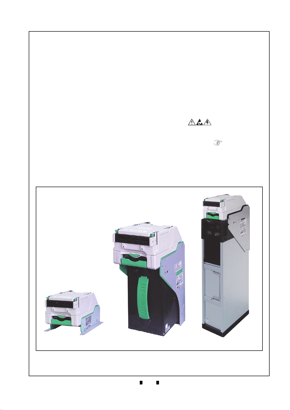
Figure 1-1 iVIZION Units
iVIZION Units
Figure 1-1 iVIZION Units
SS Specification
LD Specification
SH Specification
Next-Generation Banknote Acceptor Unit
Section 1
This section provides a general overview of the
iVIZION
Acceptor Unit, pictured in Figure 1-1. This section
is designed to help the user navigate through this
guide with ease. It includes the following information:
®
Series Next-Generation Banknote
• iVIZION Units
• Product Descriptions
• Precautions
• Primary Features
• Component Names
• Specifications
• Unit Dimensions
• Technical Contact Information
In order to make operating this device and navigating within this manual easier, the following illustrations are used:
• Safety Instructions need to be observed in order to
protect the operators and the equipment; these are
identified with Bold text and the following
pictographs:
• Special Notes affect the use of the Banknote
Validator; these are identified with italic text and
the following pictograph:
• Steps require the operator to perform specific
actions; these are identified with sequential
numbers (1, 2, 3, etc.).
P/N 960-100929R_Rev. 7 {EDP #148849} © 2017, JAPAN CASH MACHINE CO., LTD.
Page 18
1-2
Section 1 iVIZION® Series Next-Generation Banknote Acceptor Unit General Information
Photo-
coupler
RS232C USB
0: No Harness - - 1: Standard Harness
(One side cut, without USB SI/F)
Yes Yes N/A
2: Reserved - - 3: Harness with USB cable 2
(with Connector and USB I/F Cable)
Yes N/A Yes
4: SS/SH Harness
(One side cut, without USB I/F)
Yes Yes N/A
5: SS/SH Harness 2
(with Connector and USB I/F Cable)
Yes N/A Yes
6: Harness (1m one side cut, with USB
I/F Cable and JPL Connector)
Yes N/A Yes
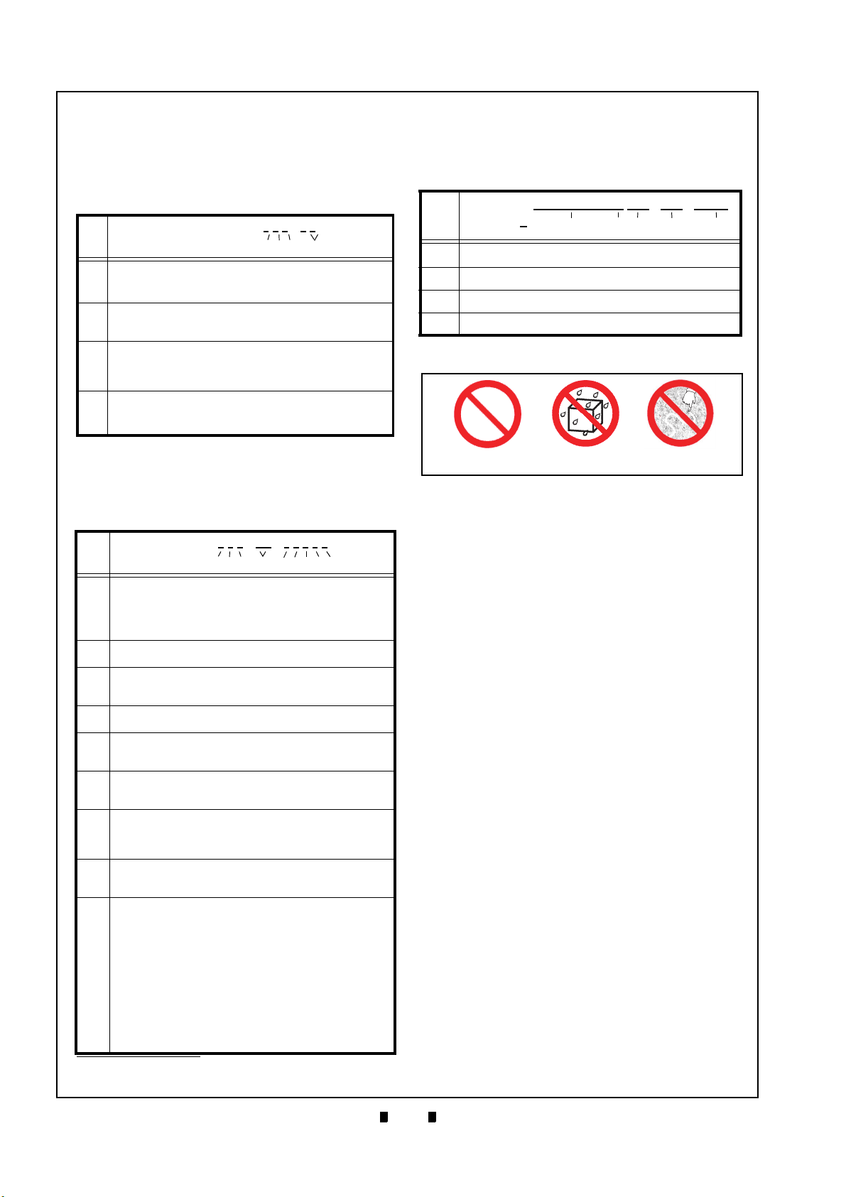
Figure 1-2 Precautionary Symbols
Type 1 Type 2 Type 3
Figure 1-2 Precautionary Symbols
Product Descriptions
Model Descriptions
Table 1-1 lists the product model number
descriptions.
Table 1-1 iVIZION Model Number Specifications
Model: iVIZION - *
No.
No (1)(2)(3) (4)
Validation Head
(1)
1: Standard
2 - 9: Reserved
CPU Board (Memory)
(2)
0: Standard
1 - 9: Reserved
Transport Unit Type
0: Standard
(3)
1: SH Specification
2 - 9: Reserved
Stacker Type
SS: Security Stacker Down
(4)
SH: Stacker Horizontal
LD: Less Down (No Stacker)
Type Descriptions
Table 1-2 lists the product type number
descriptions.
Table 1-2 iVIZION Type Number Specifications
No.
No (a)(b)(c) (d) (e)(f)(g)(h)(i)
Box Capacity
5: 500 notes (New Banknote)
(a)
9: 900 notes (New Banknote)
U: 3000 notes (Street Grade Banknote)
0: No Cash Box
Box Type
(b)
0: Standard
Box Handle
(c)
0: Standard (Blue)
1: Red Handle
Transport Unit Type
(d)
00: Standard
Bezel (Option)
(e)
0: Without Bezel
1: With LED Bezel
ICB (RFID Type)
(f)
0: None
1: ICB-Compliant (Standard) (for SS/SH Version Only)
Optional Board (Memory)
0: None (64M Bit)
(g)
1: Memory Extension Board (128M bit)
2: Reserved
Input/Output Signal Selection
(h)
P: Photo-Coupler Isolation (Standard)
R: RS232C
Typ e: *
External Harness Type
(i)
*. The number of stacked Notes depends on the Banknote’s condition.
P/N 960-100929R_Rev. 7 {EDP #148849} © 2017, JAPAN CASH MACHINE CO., LTD.
* * - 00 - * * * * *
*
* * - * *
Software Descriptions
Table 1-3 lists the product type number
descriptions.
Table 1-3 iVIZION Software Number Specifications
No.
Software: iVIZION-* * *-* * * * * - * * * - V *.* *
No (A) (B) (C) (D) (E)
(A)
Software Model Name
(B) Denomination (Country Code)
(C) Interface Protocol Name
(D) Software Version
Precautions
Symbols in Figure 1-2 are defined as follows:
1. (Type 1) Do not insert a torn, folded, or wet
Banknote; it may cause a jam inside the unit.
(Type 2) Do not expose the unit to water. The unit
2.
contains several precision electronic devices that
can be damaged if water or any liquid is sprayed
or spilled into the unit.
(Type 3) Do not install the unit in a dusty
3.
environment. Dust may affect/degrade the sensor’s performance.
User Cautions
Careful measures were taken in the design of this
product to ensure its quality; however, the following cautions pertain to all users and should be followed for safe operation.
Installation Cautions
The Installation Cautions are defined as follows:
1. Do not allow the unit to endure or operate at a
high temperature, in high humidity and/or dusty
environment.
2. Do not install the unit in an area with excessive
vibration or shock present.
3. Unit is not designed for outside installation. Be
sure that the host machine contains enough protection to avoid wet or dusty conditions when
installing in either an indoor or open-air space.
4. Avoid exposing the unit to direct sunlight/incandescent lamp illumination with a gradient angle
of 15 degrees or more, and illumination index of
3,000 Lux or less.
5. Ensure that the host machine is designed for daily
operational access for maintenance and/or clearing a Banknote Jam.
6. Do not use the Validator in environments that
may be subject to extreme temperature changes.
Page 19
1-3
General Information iVIZION® Series Next-Generation Banknote Acceptor Unit Section 1
Caution: DO NOT use any alcohol,
solvents, scouring agents or citrus
based cleaners that can damage
the plastic surfaces of the device
when cleaning it.
Caution: Make Interface Harness
connections to the Host Machine
shorter than 9.84 Feet (3 Meters) in
length. Cut off all unused portions
of the Interface Harness wiring to
avoid static electrical effects or
short circuit possibilities that
could cause damage to the Unit.
WARNING: This Unit is designed
for use with a Limited Power
Source! Design the Host Cabinet
space to meet all local related
safety standards.
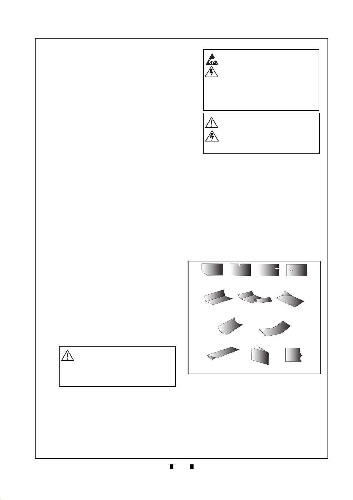
Figure 1-3 Unacceptable Banknotes
Damaged Banknotes
Wrinkled Banknotes
Curled Banknotes
Folded or Partial Banknotes
Figure 1-3 Unacceptable Banknotes
Mounting, Dismounting & Transportation
Methods for mounting, dismounting and transporting the unit:
1. Be sure to turn the Power OFF before mounting
or removing the Unit from its permanent location. Plugging or unplugging Connector Plugs
from their receptacles while the Power is ON
may cause damage to the Unit.
2. When reassembling a disassembled Unit Part,
ensure that the each part is properly replaced in
its correct original location.
3. Be sure to carry the Unit by both hands when
transporting it. Holding the Unit by one hand
may cause personal injury if the Unit accidentally
becomes disassembled and drops away.
4. Be careful not to use excessive outside pressure
on the Unit, or subject it to excessive vibration
during transportation.
Placing Foreign Objects into the Unit
Observe the following precautions when placing
foreign objects into the Unit:
1. Do not insert anything except Banknotes into the
Insertion Slot. Inserting Receipts, Stapled Tickets, Rubber Bands, or Credit Cards into the Unit
may damage the Banknote Transport path.
2. Do not inject liquids into the Banknote Insertion
Slot. Injecting water, oil or cleaning agents may
damage the Sensors within the Banknote Transport path.
Preventive Maintenance
The preventive maintenance requirements are
defined as follows:
1. Be sure to turn the Power OFF on the Unit before
beginning a maintenance procedure. The equipment can produce abnormal operating signals
while in maintenance mode that may cause personal injury.
2. If the Validator Section is dirty due to dust, foreign objects or other such debris adhering to it,
Banknote acceptance rates will degrade. Clean
the Unit once a month to keep its performance
stable.
3. Use a soft, lint-free cloth, cotton swab or a compressed air spray to clean dust and debris from
the Banknote path.
Banknote Fitness Requirements
The following Banknote types may not validate
correctly, or worse, can cause a jam and/or damage
to the unit’s Transport Path.
Banknotes exhibiting the following conditions
illustrated in Figure 1-3 should be avoided:
• torn
• excessive folds or wrinkles
• dirty
• curled
• wet
• containing foreign objects and/or oil
4. Do not disassemble the Unit incorrectly or redesign it in any way. Unauthorized use by inade-
P/N 960-100929R_Rev. 7 {EDP #148849} © 2017, JAPAN CASH MACHINE CO., LTD.
quately trained personnel, or use outside the
original manufacturer’s intent for operation voids
the warranty.
5. When the Unit is exposed to liquid such as water,
wipe with a Micro fiber cloth to dry the wet areas
immediately. Remaining liquids may affect and
degrade the Sensors and the Validation
Section’s performance.
Page 20
1-4
Section 1 iVIZION® Series Next-Generation Banknote Acceptor Unit General Information
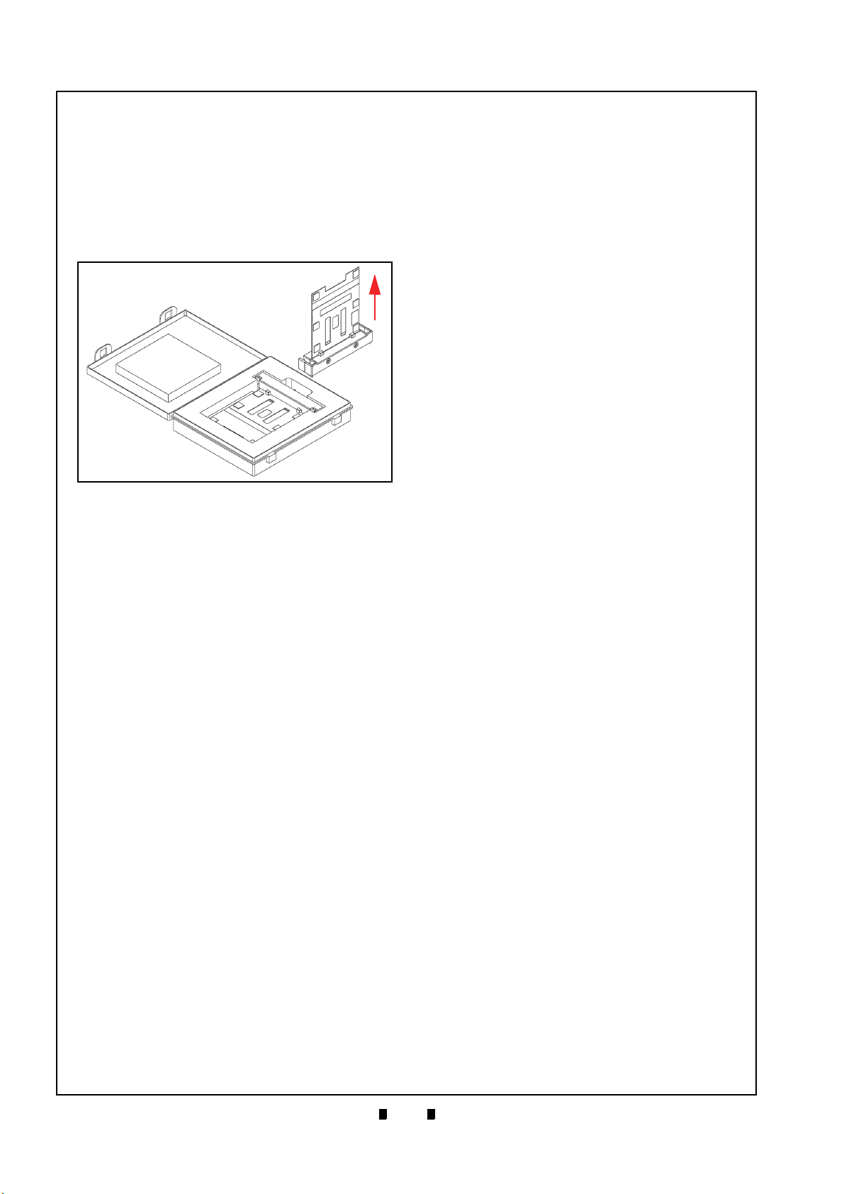
Figure 1-4 Reference Paper Handling Precau-
tions
Figure 1-4 Reference Paper Handling Precautions
a
b
KS-072/KS-089
Reference
Paper
KS-072/KS-089
Reference Paper
Shipping Carton
Reference Paper Use Precautions
When calibration, using the KS-072/KS-089 Reference Paper, is complete, protect the Reference
Paper by handling as follows:
• Ensure that the Reference Paper Carrier is kept in
an upright position following use (Figure 1-4 a) or,
replace it into its protective Shipping Carton when
calibration is complete (Figure 1-4 b).
• Do not lay the Reference Paper Carrier down on
any irregular surface, otherwise the Reference
Paper may become wrinkled making it useless for
future calibration use.
ALWAYS return each Reference Paper into its protective Shipping Carton following each use.
Primary Features
The iVIZION Series of Banknote Acceptor
contains the following primary features:
• Easily swappable single Validation Head for
inventory and maintenance efficiency.
• CIS technology allowing 100% scanning of
document details and fine line imagery.
RFID Intelligent Cash Box with lockable Frame Unit,
and designed for one-hand removal without the need to
use a Button or Lever to release the Cash Box.
P/N 960-100929R_Rev. 7 {EDP #148849} © 2017, JAPAN CASH MACHINE CO., LTD.
Page 21
1-5
General Information iVIZION® Series Next-Generation Banknote Acceptor Unit Section 1
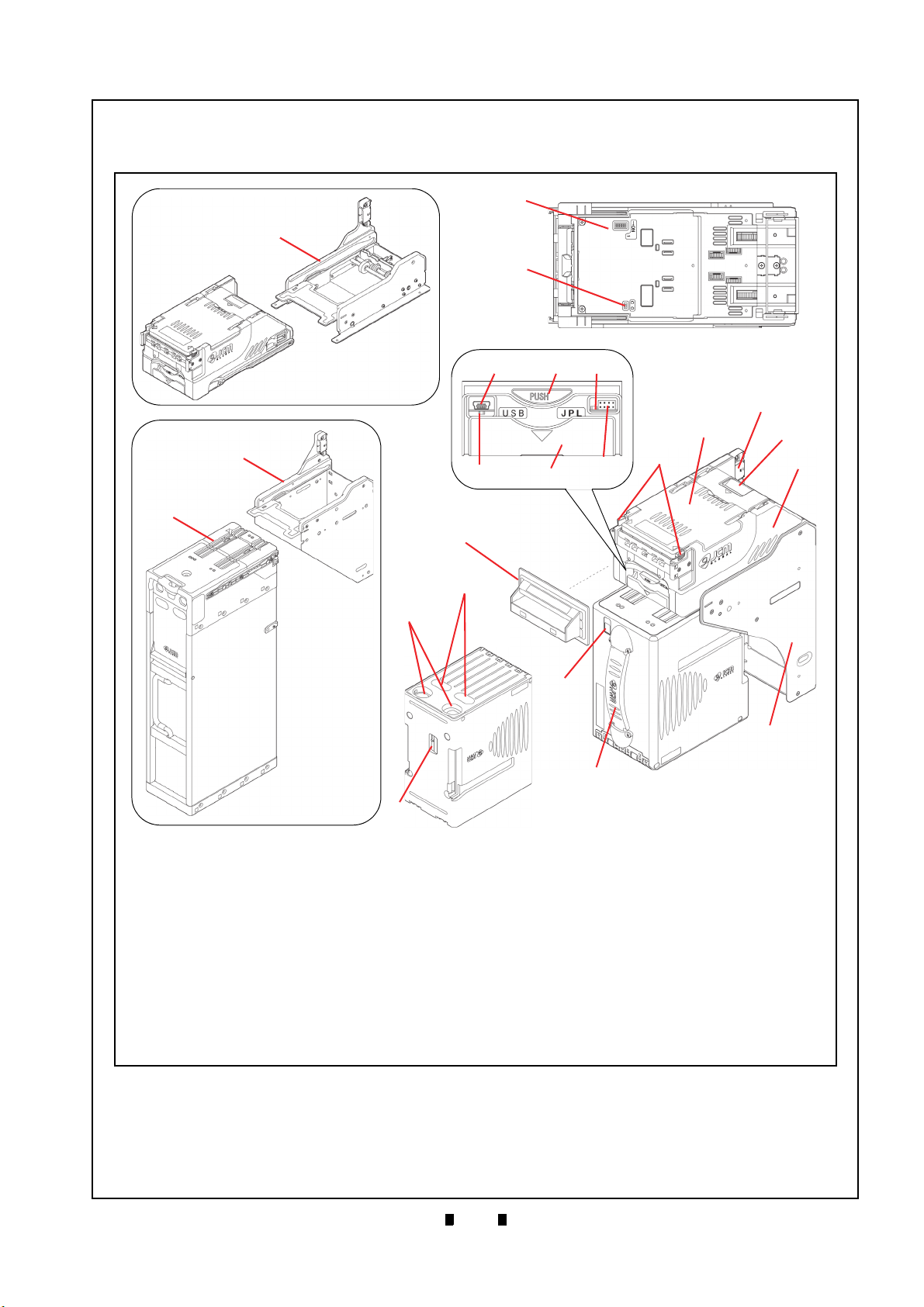
Figure 1-5 iVIZION Component Names
Figure 1-5 iVIZION Component Names
A. Acceptor Unit
B. Front Upper Guide Access Lever
(Acceptor Unit)
C. Bezel (Option)
D. Interface Connector
E. Rear Upper Guide Access Lever
(Transport Unit)
F. Transport Unit
G. Frame Housing
(SS Specification)
H. DIP Switch Block (Denomination INHIBIT)
I. DIP Switch Block (JCM Custom Private Line)
J. Acceptor Unit Release Button
K. Status LED (4 Colors: Red/Yellow/Green/Blue)
L. Front Panel Bezel JPL Connector
M. Transport Unit Release Lever
N. Power ON LED
(Green)
O. USB (Mini-B) Software Download/Calibration
& Maintenance Connector
P. Cash Box
Q. Stack Volume Indicator Window
R. Cash Box Window - Confirms the last stacked
Banknote Denomination Value
S. Lock Installation Hole
(User Provided)
T. Pusher Lever - Manually moves the Pusher
Plate down
(Activate lever to confirm the denomination value
through Cash Box Windows “R”)
U. Frame Housing (LD Specification)
V. Frame Housing (SH Specification)
W. HC Cash Box Assembly
A
B
C
D
E
F
G
H
I
J
L
K
M
N
O
Q
P
R
S
T
U
V
W
LD Frame
HC Cash Box
and Frame
Component Names
Figure 1-5 illustrates the iVIZION component names and locations.
P/N 960-100929R_Rev. 7 {EDP #148849} © 2017, JAPAN CASH MACHINE CO., LTD.
Page 22
1-6
Section 1 iVIZION® Series Next-Generation Banknote Acceptor Unit General Information
Specifications
iVIZION SS/SH Specification
Technical Specifications
Table 1-4 iVIZION Technical Specifications
98% or greater
The following banknote types are excluded:
• Banknotes with excess or poor magnetism or unclear graphics
Acceptance Rate
*
:
Banknote Types Accepted:
Barcode Coupon†:
Insertion Direction: Refer to the specific Country’s Software Information Sheet.
Processing Speed:
Validation Method: Optical
Diagnostic Indicators: Power LED, Status LED, Bezel LED (Optional)
Escrow: 1 Note
Cash Box Type
Cash Box Capacity
‡
:
**
:
Fraud Detection: Equipped
Interface
*. Refer to the specific Country’s “Software Information Sheet” for each Country’s particular Banknote acceptance rate.
†. Refer to the specific Country’s “Bar Code Coupon Specification” for more details.
‡. User supplied installed Locks (including the attached Plate, Lock and Key).
**. The number of Notes stacked depends on the Banknote’s condition.
††.The Interface Harness connecting to the Host should be less than 3m (9.84 ft).
††
:
• Double (dual) Notes
• Worn, dirty, wet, stained, torn or excessively wrinkled Banknotes
• Banknotes having folded corners or edges
• Banknotes having the wrong cut dimensions or printing displacement
• Returned Banknotes because of incorrect or failed insertion.
• Long side: SS: 110-170mm (4.33 - 6.69 in.)
SH: 110-177mm (4.33 - 6.96 in.)
• Short side: 60-85mm (2.36 - 3.35 in.)
Standard Specification
a) Read Code interleaved: 2 of 5
b) Narrow Bar: 0.5mm-0.6mm (0.019-0.023 in.)
c) Wide Bar: Narrow Bar = 3:1
d) Characters: 18 Characters
e) Print Position: Middle (by dividing a Coupon equally on the left, right, top and
bottom of the Coupon’s exact center)
f) Print Width: Wider than 10mm (0.39 in.).
Approximately 2 seconds from Banknote insertion to Vend signal output.
Approximately 3 seconds from Banknote insertion to completion of the
stacking operation.
Secure Cash Box
Intelligent Cash Box (available with RFID Specification)
SS: Standard 500 Banknotes / Large 900 Banknotes
SH: HC Cash Box: 3000 Banknotes
USB Interface: USB Specification Rev.2.0
Serial Interface: Photo-Coupler Isolation
Serial Interface: RS232C Communication Protocol.
P/N 960-100929R_Rev. 7 {EDP #148849} © 2017, JAPAN CASH MACHINE CO., LTD.
Page 23

1-7
General Information iVIZION® Series Next-Generation Banknote Acceptor Unit Section 1
Hydrothermal Condition Table
[°C]
[RH%]
Allowable Operating
Temperature and
Humidity Range
35°C/85%
50°C/40%
Environmental Specifications
Table 1-5 iVIZION Environmental Specifications
Operating Temperature: 5º C to +50º C (41º F to 122º F)
Storage Temperature: -20º C to +70º C (-4º F to 158º F)
Relative Operating Humidity: 15% to 85% RH (non-condensed)
Relative Storage Humidity: 15% to 85% RH (non-condensed)
Installation: Indoors Only
Electrical Specifications
Table 1-6 iVIZION Electrical Specifications
Supply Voltage
*
:
12V DC (-5%) to 24V DC (+10%) [NOTE: Use a Current Source Limiting
Power Supply]
Standby: 24V DC = 0.2A, 12V DC = 0.2A
Current Consumption:
Operation: 24V DC = 1.3A, 12V DC = 2.3A
Maximum: 24V DC = 3.2A, 12V DC = 3.0A
*. Use a Limited Power Source.
Structural Specifications
Table 1-7 iVIZION Structural Specifications
Weight Empty:
SS: Approximately 4.1kg (9.04 lbs)
SH: Approximately 7.6kg (16.75 lbs) (with HC Cash Box)
SS: Horizontal (Maximum gradient limitation within 50 degrees;
Mounting:
See Figure 1-10 on page 1-12)
SH: Horizontal (Maximum gradient limitation within ±5 degrees;
See Figure 1-13 on page 1-14)
Outside Dimensions: Refer to “Unit Dimensions” on page 1-10
RFID Specifications
Table 1-8 RFID Specifications
Frequency: 13.56MHz ±7kHz
Transmission Power: 200mW
P/N 960-100929R_Rev. 7 {EDP #148849} © 2017, JAPAN CASH MACHINE CO., LTD.
Page 24
1-8
Section 1 iVIZION® Series Next-Generation Banknote Acceptor Unit General Information
Hydrothermal Condition Table
[°C]
[RH%]
Allowable Operating
Temperature and
Humidity Range
35°C/85%
50°C/40%
iVIZION LD Specification
Technical Specifications
Table 1-9 iVIZION LD Technical Specifications
98% or greater
The following Banknote types are excluded:
a) Banknotes with unclear graphics
Acceptance Rate
*
:
Banknote Types Accepted:
Barcode Coupon
†
:
Insertion Direction: Refer to the specific Country’s Software Information Sheet.
Processing Speed: Approximately 2 seconds from Banknote insertion to Vend signal output.
Validation Method: Optical
Diagnostic Indicators: Power LED, Status LED, Bezel LED (Optional)
Escrow: 1 Note
Fraud Detection: Equipped
Interface
*. Refer to the specific Country’s “Software Information Sheet” for each Country’s particular Banknote acceptance rate.
†. Refer to the specific Country’s “Bar Code Coupon Specification” for more details.
‡. The Interface Harness connecting to the Host should be less than 3m.
‡
:
b) Double (dual) notes
c) Worn, dirty, wet, stained, torn or excessively wrinkled Banknotes
d) Banknotes having folded corners or edges
e) Banknotes having the wrong cut dimensions or a printing displacement
f) Returned Banknotes because of incorrect or failed insertion.
Long edge: 110-170 mm (4.33-6.69 in.)
Short edge: 60-85 mm (2.36-3.35 in.).
Standard Specification
a) Read Code interleaved: 2 of 5
b) Narrow Bar: 0.5mm-0.6mm (0.019-0.023 in.)
c) Wide Bar: Narrow Bar = 3:1
d) Characters: 18 Characters
e) Print Position: Middle (by dividing a Coupon equally on the left, right, top and
bottom of the Coupon’s exact center)
f) Print Width: Wider than 10mm (0.39 in.).
USB Interface: USB Specification Rev.2.0
Serial Interface: Photo-Coupler Isolation
Serial Interface: RS232C Communication Protocol.
Environmental Specifications
Table 1-10 iVIZION LD Environmental Specifications
Operating Temperature: 5º C to +50º C (41º F to 122º F)
Storage Temperature: -20º C to +70º C (-4º F to 158º F)
Relative Operating Humidity: 15% to 85% RH (non-condensed)
Relative Storage Humidity: 15% to 85% RH (non-condensed)
Installation: Indoors Only
P/N 960-100929R_Rev. 7 {EDP #148849} © 2017, JAPAN CASH MACHINE CO., LTD.
Page 25
1-9
General Information iVIZION® Series Next-Generation Banknote Acceptor Unit Section 1
Electrical Specifications
Table 1-11 iVIZION LD Electrical Specifications
Supply Voltage
*
:
12V DC (-5%) to 24V DC (+10%) [NOTE: Use a Current Source Limiting
Power Supply]
Standby: 24V DC = 0.2A, 12V DC = 0.2A
Current Consumption:
Operation: 24V DC = 1.3A, 12V DC = 2.3A
Maximum: 24V DC = 3.2A, 12V DC = 3.0A
*. Use a Limited Power Source.
Structural Specifications
Table 1-12 iVIZION LD Structural Specifications
Weight Empty: Approximately 2.3kg (5.07 lbs)
Mounting:
Outside Dimensions: Refer to “Unit Dimensions” on page 1-10
Horizontal (Maximum gradient limitation within 50 degrees;
See Figure 1-10 on page 1-12)
P/N 960-100929R_Rev. 7 {EDP #148849} © 2017, JAPAN CASH MACHINE CO., LTD.
Page 26
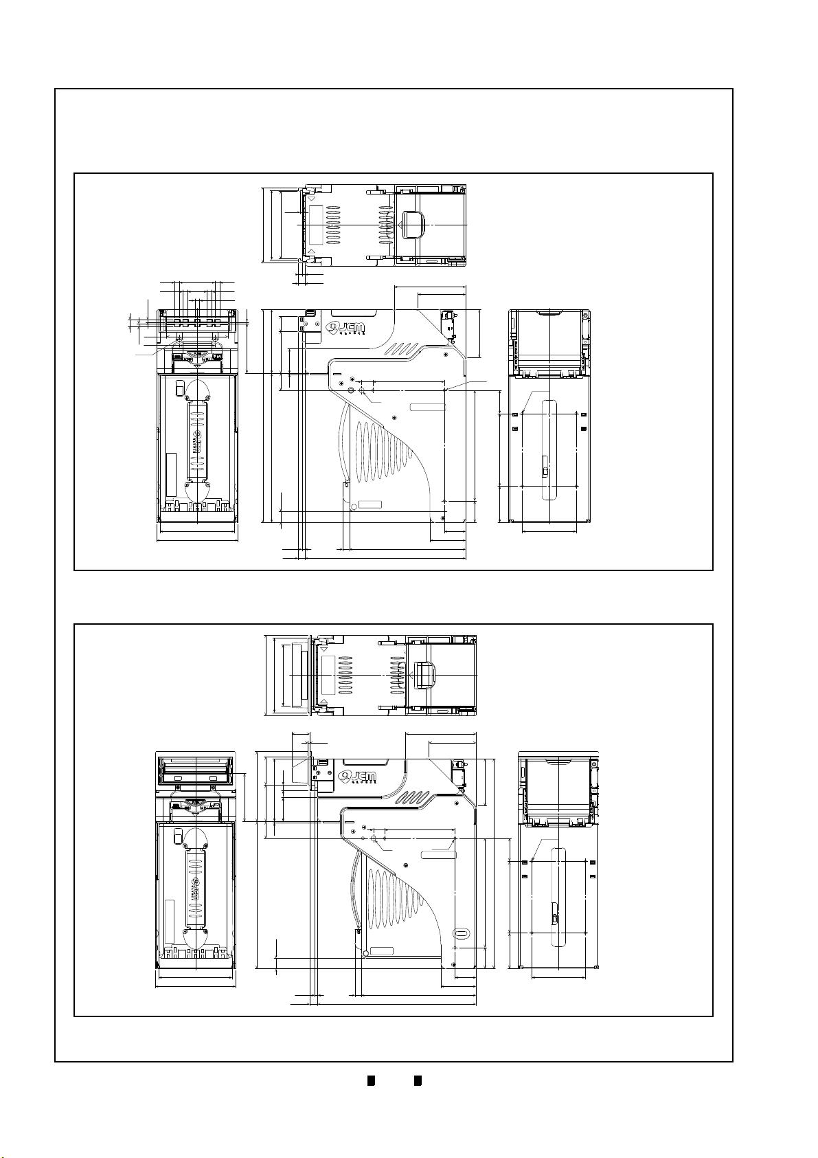
1-10
Section 1 iVIZION® Series Next-Generation Banknote Acceptor Unit General Information
Figure 1-6 iVIZION SS with Standard Cash Box
Outside Dimensions
2.5
105
97
94
89.3
21.5
58.5
34.3
2
69.5
23.7
1.6
(298)
208.7
15.2
4.2
9.2
9
225
162.9
30
50
(30)
(50.8)
155
101.6
32.6
67
100
15.8
Ø7
67
100
3-M4
4.2
9.2
6.6
6.6
49.8276.6
6.6
6.6
2-M3
9
(3.5)
3.5
86
50
104
114
75.4
4-Ø4
NOTE: All dimensions in millimeters
Figure 1-6 iVIZION SS with Standard Cash Box Outside Dimensions
Figure 1-7 iVIZION SS Unit with Standard Cash
Box/Plastic Bezel Outside Dimensions
114
106
(87.35)
68.5
99.5
40
52
89.3
7.5
(34.3)
23.7
1.6
208.7
15.2
4.2
11.2
9 162.9
225
50
30
15.8
100
3-M4
Ø7
4-Ø4
155
(298)
32.6
101.6
(50.8)
(30)
75.4
67
67
100
2.5
25.1
104
114
NOTE: All dimensions in millimeters
Figure 1-7 iVIZION SS Unit with Standard Cash Box/Plastic Bezel Outside Dimensions
Unit Dimensions
iVIZION SS Unit Outside Dimensions
Figure 1-6 illustrates the iVIZION SS Unit with Standard Cash Box Outside Dimensions.
Figure 1-7 illustrates the iVIZION SS Unit with Standard Cash Box/Plastic Bezel Outside Dimensions.
P/N 960-100929R_Rev. 7 {EDP #148849} © 2017, JAPAN CASH MACHINE CO., LTD.
Page 27
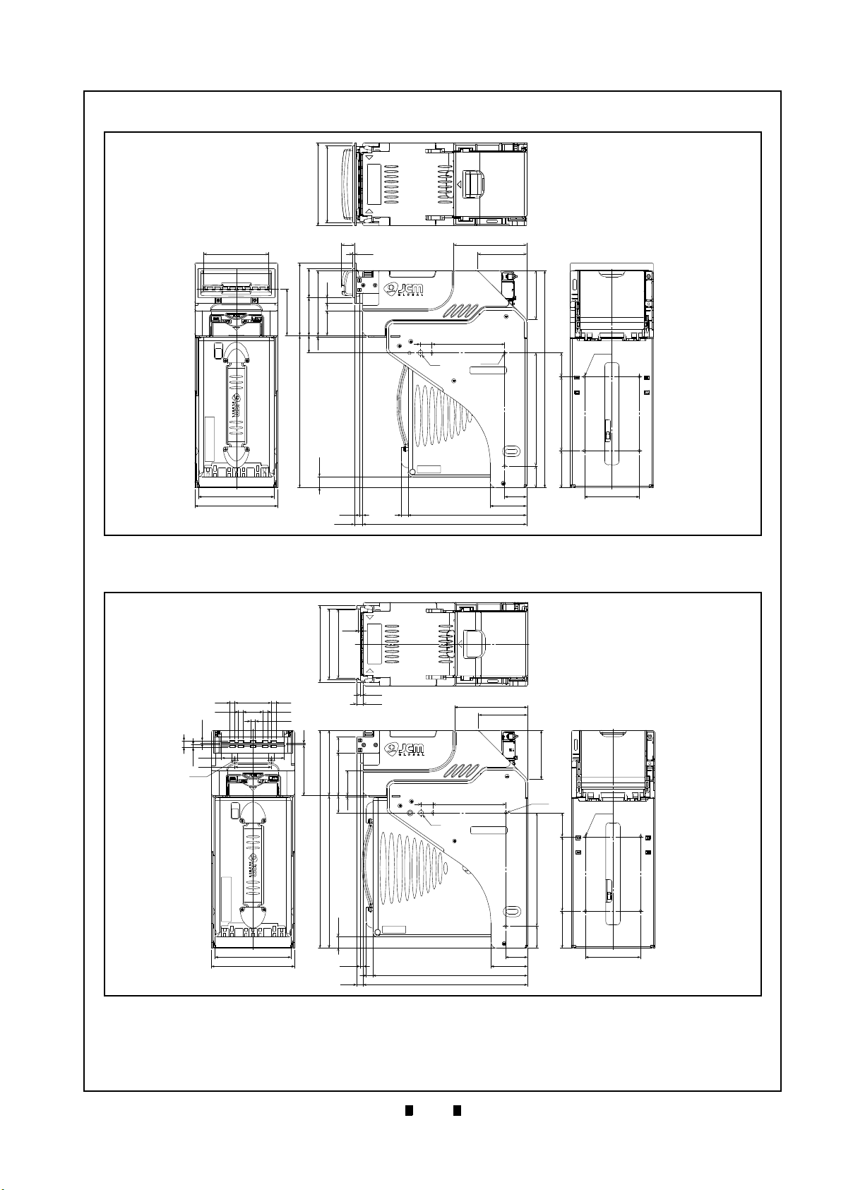
1-11
General Information iVIZION® Series Next-Generation Banknote Acceptor Unit Section 1
Figure 1-8 iVIZION SS Unit with Standard Cash
Box/Metal Bezel Outside Dimensions
114
106
4052
7.5
(34.3)
89.3
99.5
64.5
1.6
23.7
208.7
15.2
4.2
11.2
9 162.9
225
30
50
75.4
(30)
(50.8)
155
101.6
(298)
32.6
67
67
100
10015.8
3-M4
Ø7
89
104
114
4-Ø4
2.5
18
NOTE: All dimensions in millimeters
Figure 1-8 iVIZION SS Unit with Standard Cash Box/Metal Bezel Outside Dimensions
Figure 1-9 iVIZION SS Unit with Large Cash Box
Outside Dimensions
Ø7
15.8 100
3-M4
4-Ø4
67
100
67
32.6101.6
155
(30)
(50.8)
30
50
75.4
211.7
225
9
4.2
9.2
104
114
15.2
208.7
(298)
23.7
1.6
34.3
58.5
89.3
21.5
69.5
2
4.2
9.2
2.5
105
97
94
6.6
6.6
6.6
6.6
6.6
49.8
9
(3.5)
3.5
86
50
2-M3
NOTE: All dimensions in millimeters
Figure 1-9 iVIZION SS Unit with Large Cash Box Outside Dimensions
Figure 1-8 illustrates the iVIZION SS Unit with Standard Cash Box/Metal Bezel Outside Dimensions.
Figure 1-9 illustrates the iVIZION SS Unit with Large Cash Box Outside Dimensions.
P/N 960-100929R_Rev. 7 {EDP #148849} © 2017, JAPAN CASH MACHINE CO., LTD.
Page 28

1-12
Section 1 iVIZION® Series Next-Generation Banknote Acceptor Unit General Information
Figure 1-10 iVIZION SS Unit Installation/Mainte-
nance Space Requirements Diagram
NOTE: All dimensions in millimeters
72.2
336.3
2259.2
4.2
134.2
57.3
311.9
204.3
298
395.4
50°
Caution: When installing the
iVIZION SS Unit into a Host
Machine, do not mount it tilted
downward more than 50 degrees
from a Horizontal position.
NOTE: If a maintenance space clearance area
is unavailable, the iVIZION SS Unit will need
to be dismounted when maintenance
procedures are to be performed.
Maximum
Angle
Figure 1-10 iVIZION SS Unit Installation/Maintenance Space Requirements Diagram
Figure 1-11 iVIZION LD Unit Outside Dimen-
sions
4-Ø3.3
176
18021
12
225
4.2
9.2
5
134
5
34.3
58.5
21.5
89.3
69.5
29.7
2
(99.2)
11 4
50
4.2
9.2
2.5
105
97
94
100
67
67
(119)
NOTE: All dimensions in millimeters
Figure 1-11 iVIZION LD Unit Outside Dimensions
iVIZION SS Unit Installation/Maintenance Space Requirements
Figure 1-10 illustrates the iVIZION SS Unit Installation and Maintenance Space Requirements Diagram.
Figure 1-11 illustrates the iVIZION LD Unit Outside Dimensions.
P/N 960-100929R_Rev. 7 {EDP #148849} © 2017, JAPAN CASH MACHINE CO., LTD.
Page 29
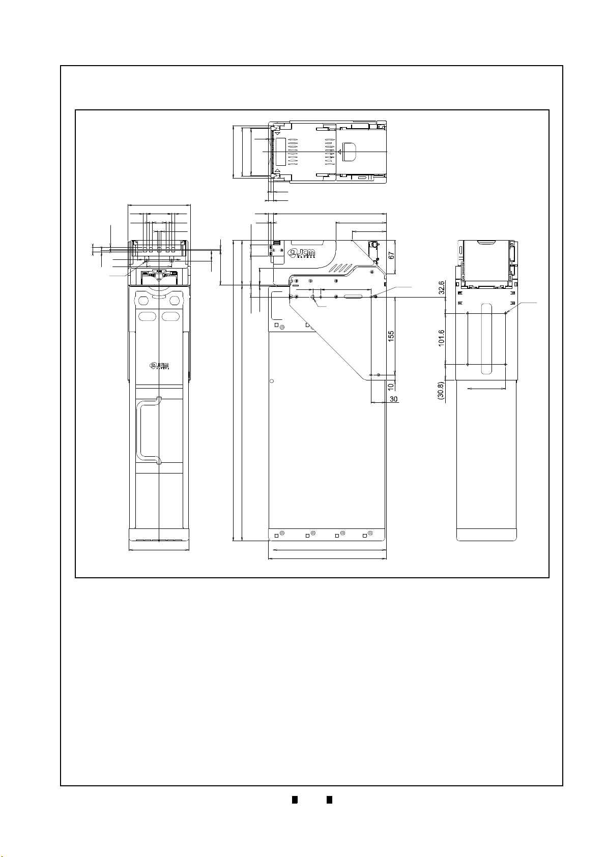
1-13
General Information iVIZION® Series Next-Generation Banknote Acceptor Unit Section 1
Figure 1-12 iVIZION SH Unit Outside Dimen-
sions
Figure 1-12 iVIZION SH Unit Outside Dimensions
NOTE: All Dimensions are in Millimeters
2.5
4.2
9.2
9.2 225
4.2
15.8
100
ø7
3xM4
67
100
75.4
4xø4
225
234
120
124
49.8
6.6
6.6
6.6
6.6
6.6
27
86
50
2xM3
(3.5)
3.5
9
2
69.5
21
89.3
58.5
34.3
21.5
23.7
1.6
(599.1)
509.8
105
97
94
iVIZION SH Entire Unit Outside Dimensions
Figure 1-12 illustrates the iVIZION SH Unit Outside Dimensions.
P/N 960-100929R_Rev. 7 {EDP #148849} © 2017, JAPAN CASH MACHINE CO., LTD.
Page 30
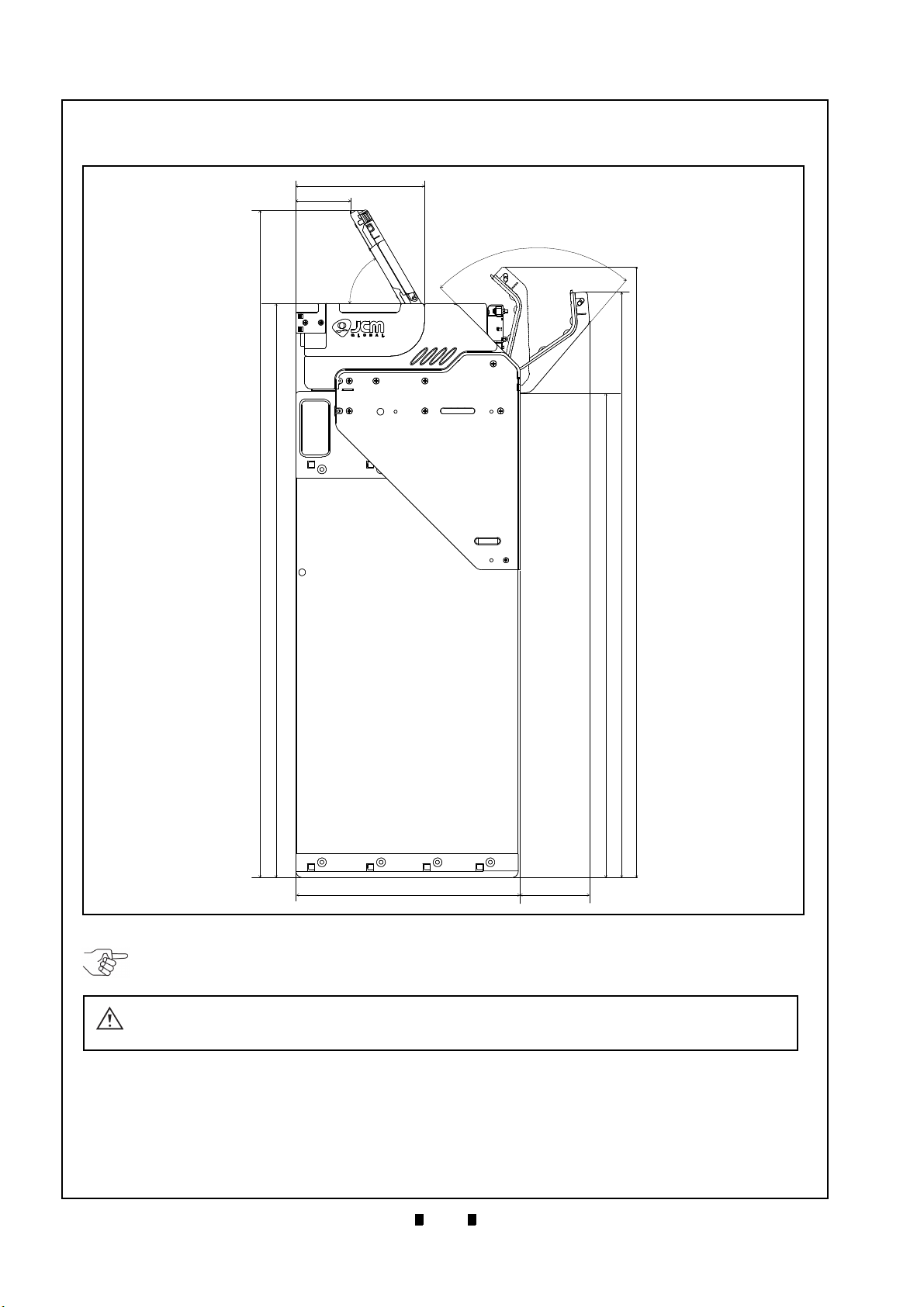
1-14
Section 1 iVIZION® Series Next-Generation Banknote Acceptor Unit General Information
Figure 1-13 iVIZION SH Unit Installation and
Maintenance Space Requirements Diagram
234.2 72.2
85.5º
5
8
.8
º
134.2
57.3
696.2
599.1
610.9
505.5
637.1
NOTE: All Dimensions are in Millimeters
Figure 1-13 iVIZION SH Unit Installation and Maintenance Space Requirements Diagram
NOTE: The iVIZION HC Cash Box is installed as it is hanging on the SH unit. Do not allow the Cash Box to
touch a Host Machine. Ensure that there is sufficient space below the Cash Box for its removal.
Caution: When installing the iVIZION SH Unit into a Host Machine, do not mount it
tilted downward more than ±5 degrees from a Horizontal position.
iVIZION SH Unit Installation/Maintenance Space Requirements
Figure 1-13 illustrates the iVIZION SH Unit Installation and Maintenance Space Requirements Diagram.
P/N 960-100929R_Rev. 7 {EDP #148849} © 2017, JAPAN CASH MACHINE CO., LTD.
Page 31

1-15
General Information iVIZION® Series Next-Generation Banknote Acceptor Unit Section 1
Figure 1-14 iVIZION Standard Cash Box Dimen-
sions
104
10.8
22.1
7.4
28
36
9
15
161
0.3
0.3
3.4
27.1
6
21.7
191
184.5
115.2
40.8
12.3
48.1
30
86.6
43.5
NOTE: All dimensions in millimeters
Figure 1-14 iVIZION Standard Cash Box Dimensions
Figure 1-15 iVIZION Large Cash Box Dimen-
sions
NOTE: All dimensions in millimeters
0.3
209.8
15
9
36
28
104
10.8
22.1
3.4
27.1
0.3
86.6
12.3
40.8
115.2
184.5
191
21.7
7.4
6
48.1
30
43.5
Figure 1-15 iVIZION Large Cash Box Dimensions
iVIZION Cash Box Outside Dimensions
Standard Cash Box Outside Dimensions
Figure 1-14 illustrates the iVIZION Standard Cash Box Outside Dimensions.
Large Cash Box Outside Dimensions
Figure 1-15 illustrates the iVIZION Large Cash Box Outside Dimensions.
P/N 960-100929R_Rev. 7 {EDP #148849} © 2017, JAPAN CASH MACHINE CO., LTD.
Page 32

1-16
Section 1 iVIZION® Series Next-Generation Banknote Acceptor Unit General Information
Figure 1-16 iVIZION HC Cash Box Dimensions
86
26.8
3.3
507.3
20.5
120
29
232
36.6
28.5
NOTE: All dimensions in millimeters
Figure 1-16 iVIZION HC Cash Box Dimensions
HC Cash Box Outside Dimensions
Figure 1-16 illustrates the iVIZION HC Cash Box Outside Dimensions.
P/N 960-100929R_Rev. 7 {EDP #148849} © 2017, JAPAN CASH MACHINE CO., LTD.
Page 33

1-17
General Information iVIZION® Series Next-Generation Banknote Acceptor Unit Section 1
Technical Contact Information
To obtain further technical information regarding the iVIZION Unit, please contact the nearest location
listed below:
Americas
JCM American
Phone: +1-702-651-0000
Fax: +1-702-644-5512
925 Pilot Road, Las Vegas, NV 89119
E-mail: support@jcmglobal.com
Europe, Middle East, Africa & Russia
JCM Europe GmbH
Phone: +49-211-530-645-60
Fax: +49-211-530-645-85
Mündelheimer Weg 60
D-40472 Düsseldorf Germany
E-mail: support@jcmglobal.eu
UK & Ireland
JCM Europe (UK Office)
Phone: +44 (0) 190-837-7331
Fax: +44 (0) 190-837-7834
Unit B, Third Avenue
Denbigh West Business Park
Bletchley, Milton Keynes,
Asia and Oceania
JCM Gold (HK) Ltd.
Phone: +852-2429-7187
Fax: +852-2929-7003
Unit 1-7, 3/F., Favor Industrial Centre
2-6 Kin Hong Street, Kwai Chung,
N.T. Hong Kong
E-mail: asiasupport@jcmglobal.com
JAPAN CASH MACHINE CO., LTD. (HQ)
Phone: +81-6-6703-8400
Fax: +81-6-6707-0348
2-3-15, Nishiwaki, Hirano-ku, Osaka 547-0035
JAPAN
E-mail: Shohin@jcm-hq.co.jp
The JCM Website for all locations is:
http://www.jcmglobal.com
Buckinghamshire MK1 1DH, UK
E-mail: support@jcmglobal.eu
P/N 960-100929R_Rev. 7 {EDP #148849} © 2017, JAPAN CASH MACHINE CO., LTD.
Page 34

1-18
Section 1 iVIZION® Series Next-Generation Banknote Acceptor Unit General Information
THIS PAGE INTENTIONALLY LEFT BLANK
P/N 960-100929R_Rev. 7 {EDP #148849} © 2017, JAPAN CASH MACHINE CO., LTD.
Page 35

2-1
iVIZION® Series
2 INSTALLATION
Figure 2-1 Interface Harness Installation Loca-
tion
a
b
b
c
d
e
Figure 2-1 Interface Harness Installation Location
Figure 2-2 M4 Screws Locations (Left/Right
Side)
Figure 2-2 M4 Screws Locations (Left/Right Side)
Figure 2-3 Flat Head Screws Locations (Rear
Side)
Figure 2-3 Flat Head Screws Locations
(Rear Side)
Next-Generation Banknote Acceptor Unit
Section 2
This section provides installation and operating
instructions for the iVIZION
®
Series Next-Generation Banknote Acceptor Unit. The information
within this section contains the following features:
• Installation Procedure
• DIP Switch Configurations
• Connector Pin Assignments
• Preventive Maintenance
• Cleaning Procedure
• Standard Interface Circuit Schematics
• Operation Flowcharts
Installation Procedure
Mounting holes are provided in each Frame Unit to
attach the iVIZION to a related Machine during
installation. Select and perform the following steps
to install the iVIZION Unit in the related
Machine’s particular Frame configuration:
1. Install the Interface Harness to the Frame
Grounding Plate (FG PLT) (Figure 2-1 a) using
the two (2) Floating Collars (Figure 2-1 b), the
single (1) M2.6x12 W Washer Screw (Figure 2-1
c), the single (1) M2.6x10 W Washer Screw (Fig-
ure 2-1 d) and the single (1) M2.6 Nylon Nut
(Figure 2-1 e) onto the Frame Assembly. See the
Figure 2-1 circled inset to visually see the assembly completed as required.
2. When a side mounting configuration is preferred,
bolt the left and right side of the
Frame into its intended
tion using six (6) M4 Screws on both sides of the
Frame (3 Screws on each side as shown in Figure
2-2).
3. When an end mounting configuration is preferred, remove the Cash Box and attach the rear
end of the
location using four (4) UNC6-32 Flat Head
Screws from inside the back end of the Frame as
shown in Figure 2-3.
iVIZION Frame into its intended
related Machine’s loca-
iVIZION
P/N 960-100929R_Rev. 7 {EDP #148849} © 2017, JAPAN CASH MACHINE CO., LTD.
Page 36

2-2
Section 2 iVIZION® Series Next-Generation Banknote Acceptor Unit Installation
NOTE: The length from Frame surface to
the edge of the M4 Screws should be within
4mm in order not to puncture the Plastic
Surface of the iVIZION Frame when a side
mounting configuration is preferred.
NOTE: When installing the iVIZION LD
Version Unit into a related Machine, the
iVIZION Optional LD Version Unit Installation
detailed information on
page 2-11.
Figure 2-4 Lock Size
Figure 2-4 Lock Size
2x16.2
2
x
φ
1
9
.1
+
0
.
1
0
+0.1
0
Use a Key Spacer if backlash
affects lock/unlock function.
5
/
8
i
n
.
(
1
5
.
9
m
m
)
2
0.
5m
m
1
-1
/
8
in
.
(
2
8
.
6
mm
)
* The length of each lock indicated followed standard size.
Millimeters in brackets for inches are only reference.
Figure 2-5 Unlock Rotation Direction
Figure 2-5 Unlock Rotation Direction
5/8 in. or 1-1/8 in. Lock
20.5mm Lock
NOTE: When using only one lock, install the
Key Cap in the unused key hole (Figure 2-
6).
Figure 2-6 Key Cap Installation
Figure 2-6 Key Cap Installation
Use Key Cap
When installing the iVIZION SH Unit into the Host
Machine, refer to the Figure 1-12 “iVIZION SH
Unit Outside Dimensions” on page 1-13.
Lock Installation
One or two security locks can be installed onto a
iVIZION Cash Box. When installing a security
lock, the following attachment accessories may be
required:
• Key Spacers
• Plate Lock Keys
• Key Cap Attachment
Choose a Lock that fits a standard size hole dimension format (Figure 2-4). In addition, when two
locks are installed, both locks must be identical.
Unlock Procedure
Each Lock has a different rotation direction to
unlock. Make sure when the lock(s) are installed
the rotation is in the correct direction(s) (Figure 2-
5).
P/N 960-100929R_Rev. 7 {EDP #148849} © 2017, JAPAN CASH MACHINE CO., LTD.
Page 37

2-3
Installation iVIZION® Series Next-Generation Banknote Acceptor Unit Section 2
This portion provides the denomination DIP Switch Block Settings for the iVIZION Unit.
SW1
JP1
O
↔
C
Mark
SW1
JP2
JP3
R ↔ P
R ↔ P
Mark
NOTE: When changing the type of iVIZION
Serial Communications, Switches JP2 and
JP3 located on the Controller CPU Board
must be set to identical switch positions.
Primary LED Indications
The iVIZION Unit’s two LEDs illuminate different colors when various operating and error conditions
occur.
DIP Switch Configurations
Table 2-1 Denomination INHIBIT DIP Switch
Settings
Validation CPU Board SW1
Switch
No.
Switch ON Switch OFF
1 VEND 1 INHIBIT VEND 1 ACCEPT
2 VEND 2 INHIBIT VEND 2 ACCEPT
3 VEND 3 INHIBIT VEND 3 ACCEPT
4 VEND 4 INHIBIT VEND 4 ACCEPT
5 VEND 5 INHIBIT VEND 5 ACCEPT
6 VEND 6 INHIBIT VEND 6 ACCEPT
7 VEND 7 INHIBIT VEND 7 ACCEPT
8
*. Not Applicable (N/A). Used to enter “Test Mode”.
N/A
*
OFF (Fixed)
Table 2-2 JCM Private Line DIP Switch Setting
Validation CPU Board JP1
Switch
No.
Non-Marked (O) Marked (C)
Table 2-3 Software DIP Switch Settings
Controller CPU Board SW1
Switch
No.
1
Switch ON Switch OFF
N/A
*
OFF (Fixed)
2 N/A* OFF (Fixed)
3 N/A* OFF (Fixed)
4 N/A* OFF (Fixed)
*. Not Applicable (N/A). Never Switched to ON.
Table 2-4 Serial Communication DIP Switch
Settings
Controller CPU Board JP2 & JP3
Switch
No.
JP2
JP3 RS232C
Non-Marked (R) Marked (P)
RS232C
Photo-Coupler
Isolation (Standard)
Photo-Coupler
Isolation (Standard)
RS-485 Resistance
1
Terminated
RS-485 Resistance
Un-Terminated
Table 2-5 LED Error Pattern Indications
No. Condition
1OFF
Power LED
Extinguished (OUT) Extinguished (OUT)
2 Initializing Lit Green Blue Flashes
3 Stand-by
4 Reject
5 Banknote Jam
6 Abnormal Error
Lit Green
Lit Green Green Flashes
Lit Green Yellow Flashes
Lit Green Red Flashes
7 Downloading Lit Green
8 Performance Test (Stand-by)
*. The Power LED lights Green when Power is supplied to the Unit.
Lit Green Lit Blue
LED Indications
*
Status LED
Extinguished
(OUT)
Lit Red
Lit Green
P/N 960-100929R_Rev. 7 {EDP #148849} © 2017, JAPAN CASH MACHINE CO., LTD.
Page 38

2-4
Section 2 iVIZION® Series Next-Generation Banknote Acceptor Unit Installation
Back Side View
Socket Housing (Transport Unit Side): DR1B026JA1 (JCM)
Pin Housing (Frame Side): DR1R026PA1 (JCM)
Contact Type (Frame Side): D02-22-26P-10000 (JAE) (Poles except 1, 9, 18 & 26)
Recommended Wire: UL1061 AWG#26
Contact Type (Frame Side): D02-22-22P-10000 (JAE) (Pole# 1, 9, 18 & 26)
Recommended Wire: UL1061 AWG#24
Connector Pin Assignments
Table 2-6 lists the iVIZION SS/LD Interface Connector Pin Assignments.
Table 2-6 iVIZION SS/LD USB Connection Pin Assignments
Pin No. Signal Name
1
24V DC (POWER) POWER
I/O
* †
+24V DC Power
Function
2 M-RESET IN Banknote Acceptor Master Reset Input Signal Line
3 USB- IN/OUT USB Communication Input/Output Signal Line
4 USB+ IN/OUT USB Communication Input/Output Signal Line
5 USB GND SG USB Communication Ground (0V DC)
6TTL-TXDOUT-
7TTL-RXD IN-
8 LED POWER OUT LED Drive Line (anode)
9 24V DC (POWER) POWER +24V DC Power
10 RS232 GND SG -
11 TXD OUT -
12 I/F +12V DC IN Interface Power Supply (+12VDC)
13 Vbus IN USB Communication Vbus Signal Line (+5V DC)
14 JP+ IN/OUT -
15 TTL-G SG -
16 LED- IN LED Drive Line (cathode)
17 ccTalk (P) IN/OUT -
18 POWER GND POWER Power Ground (0V DC)
19 I/F GND SG -
20 RXD IN -
21 DET-GND IN Connect to DET (Pin-22)
22 DET OUT Connect to DET GND (Pin-21)
23 JP- IN/OUT -
24 SU SELECT IN
SS/SU Selection
‡
25 ccTalk (S) IN/OUT -
26 POWER GND POWER Power Ground (0V DC)
*. I/O (Input/Output) Terminal as viewed from outside the Banknote Acceptor.
†. SG = Signal Ground.
‡. No Connection = SS Version, Connect to any unused SG (Pin #10, Pin #15 or Pin #19) = SU Version.
P/N 960-100929R_Rev. 7 {EDP #148849} © 2017, JAPAN CASH MACHINE CO., LTD.
Page 39

2-5
Installation iVIZION® Series Next-Generation Banknote Acceptor Unit Section 2
Back Side View
Socket Housing (Transport Unit Side): DR1B026JA1 (JCM)
Pin Housing (Frame Side): DR1R026PA1 (JCM)
Contact Type (Frame Side): D02-22-26P-10000 (JAE) (Poles except 1, 9, 18 & 26)
Recommended Wire: UL1061 AWG#26
Contact Type (Frame Side): D02-22-22P-10000 (JAE) (Pole# 1, 9, 18 & 26)
Recommended Wire: UL1061 AWG#24
Connector Pin Assignments (Continued 1)
Table 2-7 lists the iVIZION SS/LD Photo-Coupler Connector Pin Assignments.
Table 2-7 iVIZION SS/LD Photo-Coupler Connector Pin Assignments
Pin No. Signal Name
1 24V DC (POWER) POWER
I/O
* †
+24V DC Power
Function
2 M-RESET IN Banknote Acceptor Master Reset Input Signal Line
3 USB- IN/OUT -
4 USB+ IN/OUT -
5 USB GND SG -
6TTL-TXDOUT-
7TTL-RXD IN-
8 LED POWER OUT LED Drive Line (anode)
9 24V DC (POWER) POWER +24V DC Power
10 RS232 GND SG -
11 TXD OUT Serial Communication Output Signal Line
12 I/F +12V DC IN Interface Power Supply (+12VDC)
13 Vbus IN -
14 JP+ IN/OUT -
15 TTL-G SG -
16 LED- IN LED Drive Line (cathode)
17 ccTalk (P) IN/OUT -
18 POWER GND POWER Power Ground (0V DC)
19 I/F GND SG Photo-Coupler Communication GND
20 RXD IN Serial Communication Input Signal Line
21 DET-GND IN Connect to DET (Pin-22)
22 DET OUT Connect to DET GND (Pin-21)
23 JP- IN/OUT -
24 SU SELECT IN
SS/SU Selection
‡
25 ccTalk (S) IN/OUT -
26 POWER GND POWER Power Ground (0V DC)
*. I/O (Input/Output) Terminal as viewed from outside the Banknote Acceptor.
†. SG = Signal Ground.
‡. No Connection = SS Version, Connect to any unused SG (Pin #10 or Pin #15) = SU Version.
P/N 960-100929R_Rev. 7 {EDP #148849} © 2017, JAPAN CASH MACHINE CO., LTD.
Page 40

2-6
Section 2 iVIZION® Series Next-Generation Banknote Acceptor Unit Installation
Back Side View
Socket Housing (Transport Unit Side): DR1B026JA1 (JCM)
Pin Housing (Frame Side): DR1R026PA1 (JCM)
Contact Type (Frame Side): D02-22-26P-10000 (JAE) (Poles except 1, 9, 18 & 26)
Recommended Wire: UL1061 AWG#26
Contact Type (Frame Side): D02-22-22P-10000 (JAE) (Pole# 1, 9, 18 & 26)
Recommended Wire: UL1061 AWG#24
Connector Pin Assignments (Continued 2)
Table 2-8 lists the iVIZION SS/LD RS232C Connector Pin Assignments.
Table 2-8 iVIZION SS/LD RS232C Connector Pin Assignments
Pin No. Signal Name
1 24V DC (POWER) POWER
I/O
* †
+24V DC Power
Function
2 M-RESET IN Banknote Acceptor Master Reset Input Signal Line
3 USB- IN/OUT -
4 USB+ IN/OUT -
5 USB GND SG -
6TTL-TXDOUT-
7TTL-RXD IN-
8 LED POWER OUT LED Drive Line (anode)
9 24V DC (POWER) POWER +24V DC Power
10 RS232C GND SG RS232C Communication Ground
11 TXD OUT Serial Communication Output Signal Line
12 I/F + 12V DC IN Interface Power Supply (+12V DC)
13 Vbus IN -
14 JP+ IN/OUT -
15 TTL-G SG -
16 LED- IN LED Drive Line (cathode)
17 ccTalk (P) IN/OUT -
18 POWER GND POWER Power Ground (0V DC)
19 I/F GND SG -
20 RXD IN Serial Communication Input Signal Line
21 DET-GND IN Connect to DET (Pin-22)
22 DET OUT Connect to DET GND (Pin-21)
23 JP- IN/OUT -
24 SU SELECT IN
SS/SU Selection
‡
25 ccTalk (S) IN/OUT -
26 POWER GND POWER Power Ground (0V DC)
*. I/O (Input/Output) Terminal as viewed from outside the Banknote Acceptor.
†. SG = Signal Ground
‡. No Connection = SS Version, Connect to any unused SG (Pin #15 or Pin #19) = SU Version.
P/N 960-100929R_Rev. 7 {EDP #148849} © 2017, JAPAN CASH MACHINE CO., LTD.
Page 41

2-7
Installation iVIZION® Series Next-Generation Banknote Acceptor Unit Section 2
Back Side View
Socket Housing (Transport Unit Side): DR1B026JA1 (JCM)
Pin Housing (Frame Side): DR1R026PA1 (JCM)
Contact Type (Frame Side): D02-22-26P-10000 (JAE) (Poles except 1, 9, 18 & 26)
Recommended Wire: UL1061 AWG#26
Contact Type (Frame Side): D02-22-22P-10000 (JAE) (Pole# 1, 9, 18 & 26)
Recommended Wire: UL1061 AWG#24
Connector Pin Assignments (Continued 3)
Table 2-9 lists the iVIZION SS/LD ccTalk Connector Pin Assignments.
Table 2-9 iVIZION SS/LD ccTalk Connector Pin Assignments
Pin No. Signal Name
1 24V DC (POWER) POWER
I/O
* †
+24V DC Power
Function
2 M-RESET IN Banknote Acceptor Master Reset Input Signal Line
3 USB- IN/OUT -
4 USB+ IN/OUT -
5 USB GND SG -
6TTL-TXDOUT-
7TTL-RXD IN-
8 LED POWER OUT LED Drive Line (anode)
9 24V DC (POWER) POWER +24V DC Power
10 RS232C GND SG -
11 TXD OUT -
12 I/F + 12V DC IN Interface Power Supply (+12VDC)
13 Vbus IN -
14 JP+ IN/OUT -
15 TTL-G SG -
16 LED- IN LED Drive Line (cathode)
17 ccTalk (P) IN/OUT ccTalk Communication Power Supply Line
18 POWER GND POWER Power Ground (0V DC)
19 I/F GND SG -
20 RXD IN -
21 DET-GND IN Connect to DET (Pin-22)
22 DET OUT Connect to DET GND (Pin-21)
23 JP- IN/OUT -
24 SU SELECT IN
SS/SU Selection
‡
25 ccTalk (S) IN/OUT ccTalk Communication Signal Line
26 POWER GND POWER Power Ground (0V DC)
*. I/O (Input/Output) Terminal as viewed from outside the Banknote Acceptor.
†. SG = Signal Ground.
‡. No Connection = SS Version, Connect to any unused SG (Pin #10, Pin #15 or Pin #19) = SU Version.
P/N 960-100929R_Rev. 7 {EDP #148849} © 2017, JAPAN CASH MACHINE CO., LTD.
Page 42

2-8
Section 2 iVIZION® Series Next-Generation Banknote Acceptor Unit Installation
Back Side View
Socket Housing (Transport Unit Side): DR1B026JA1 (JCM)
Pin Housing (Frame Side): DR1R026PA1 (JCM)
Contact Type (Frame Side): D02-22-26P-10000 (JAE) (Poles except 1, 9, 18 & 26)
Recommended Wire: UL1061 AWG#26
Contact Type (Frame Side): D02-22-22P-10000 (JAE) (Pole# 1, 9, 18 & 26)
Recommended Wire: UL1061 AWG#24
Connector Pin Assignments (Continued 4)
Table 2-10 lists the iVIZION SS/LD TTL Connector Pin Assignments.
Table 2-10 iVIZION SS/LD TTL Connector Pin Assignments
Pin No. Signal Name
1 24V DC (POWER) POWER
I/O
* †
+24V DC Power
Function
2 M-RESET IN Banknote Acceptor Master Reset Input Signal Line
3 USB- IN/OUT -
4 USB+ IN/OUT -
5 USB GND SG -
6 TTL-TXD OUT TTL Communication Output Signal Line
7 TTL-RXD IN TTL Communication Input Signal Line
8 LED POWER OUT LED Drive Line (anode)
9 24V DC (POWER) POWER +24V DC Power
10 RS232C GND SG -
11 TXD OUT -
12 I/F + 12V DC IN Interface Power Supply (+12VDC)
13 Vbus IN -
14 JP+ IN/OUT -
15 TTL-G SG -
16 LED- IN LED Drive Line (cathode)
17 ccTalk (P) IN/OUT -
18 POWER GND POWER Power Ground (0V DC)
19 I/F GND SG -
20 RXD IN -
21 DET-GND IN Connect to DET (Pin-22)
22 DET OUT Connect to DET GND (Pin-21)
23 JP- IN/OUT -
24 SU SELECT IN
SS/SU Selection
‡
25 ccTalk (S) IN/OUT -
26 POWER GND POWER Power Ground (0V DC)
*. I/O (Input/Output) Terminal as viewed from outside the Banknote Acceptor.
†. SG = Signal Ground.
‡. No Connection = SS Version, Connect to any unused SG (Pin #10, Pin #15 or Pin #19) = SU Version.
P/N 960-100929R_Rev. 7 {EDP #148849} © 2017, JAPAN CASH MACHINE CO., LTD.
Page 43

2-9
Installation iVIZION® Series Next-Generation Banknote Acceptor Unit Section 2
CN7
Polarizing Pin
ID Pin No.4
Connector
Embossed
Connector Pin Assignments (Continued 5)
Table 2-11 lists the iVIZION SS/LD Bezel Connector Pin Assignments.
Table 2-11 iVIZION SS/LD Bezel JPL (CN7) Connection Pin Assignments
Front Side View
Box Pin Header (Control CPU Board Side): A3B-8PA-2DS (71) (HRS) JCM Custom
Pin No. Signal Name
Socket Housing (Bezel Side): A3B-8D-2C (HRS)
Contact Type (Bezel Side): A3B-2630SCFC (HRS)
Polarizing Pin: A3-GPIN (HRS)
Recommended Wire: UL1007 AWG#24~30
†
I/O
*
Function
1 JP+ IN/OUT -
2 - - Polarizing Pin Key
3 JP- IN/OUT -
4 5V DC OUT 5V DC Power Supply (Maximum 300mA)
5 VIN OUT LED Drive Power Supply 12V DC/24V DC (Maximum 300mA)
6GNDSG-
7 LED POWER OUT
LED Power Supply 5V (Maximum 20mA Current Limitation
Resistance)
8 LED 1 IN LED Drive Line (cathode) Maximum Sink Current: 300mA
*. Caution: The Embossed Numbers located on the Polarizing Pin Connector, and on the CN7 Connector Numbers indicated in Table 2-11 are different. The Polarizing Pin Key
should be inserted into Pin Position No.4 of the Polarizing Pin Connector.
†. I/O (Input/Output) Terminal as viewed from outside the Banknote Acceptor.
P/N 960-100929R_Rev. 7 {EDP #148849} © 2017, JAPAN CASH MACHINE CO., LTD.
Page 44

2-10
Section 2 iVIZION® Series Next-Generation Banknote Acceptor Unit Installation
Figure 2-7 Retrieving Banknote
Remove
Figure 2-7 Retrieving Banknote
Figure 2-8 Open the Upper Guides
a) Acceptor Unit Upper Guide Access Lever
b) Transport Unit Upper Guide Access Lever
Open
Open
b
a
Remove
Remove
Hidden
Figure 2-8 Open the Upper Guides
Figure 2-9 Retrieving Cash Box Banknote Jam
Figure 2-9 Retrieving Cash Box Banknote Jam
Pull Out
a
c
b
Caution: Do not allow any fluid to remain
on internal components, especially on
the Anti-String Mechanism and in the
Feed-in Sensor’s grooved areas.
Caution: Do not use Alcohol, thinner or
citrus based products for cleaning any
Banknote transport Sensors or surfaces.
The lenses can become clouded by
chemical evaporation residue that may
cause acceptance errors.
NOTE: When closing the Acceptor or
Transport Unit’s Upper Guides, ensure that
they click firmly into place when being
closed. Also, when reassembling the
iVIZION Unit, ensure that it re-seats correctly
into place when the reassembly is complete.
Preventive Maintenance
Retrieving Banknotes
To retrieve Cash Box deposited Banknotes perform
the following steps:
1. Release the Cash Box from the Frame and pull it
forward.
2. Unlock the Cash Box with a User supplied Key.
3. Open the Cash Box Door and retrieve deposited
Banknotes as illustrated in Figure 2-7.
Clearing a Banknote Jam
To retrieve a jammed Banknote jammed inside the
Banknote Acceptor Head proceed as follows:
1. Open the Acceptor Unit’s Upper Guide by pressing in on the two (2) Upper Guide Access Buttons
(Figure 2-8 a) located on each side of the Upper
Guide, and lift the Acceptor top up and open and
remove the jammed Banknote.
2. If the jammed Banknote is not found in the
Acceptor Unit, then
3. Open the Transport Unit’s Upper Guide by pressing in on the Upper Guide Access Lever (Figure
2-8 b) located in the center of the Upper Guide,
and lift the Transport Section up and open and
remove the jam.
5. A jammed Banknote may also be present on top
of the Cash Box; remove it if present at this
location (Figure 2-9 c).
Cleaning Procedure
To clean the lenses, use a lint-free, Micro-Fiber
Cloth and a mild non-abrasive detergent such as
liquid dish soap mixed with water to wipe the dirt
from the Lenses. It is important to keep the
Banknote Path, Rollers, and Belts clean. Use a softlint free, Micro-Fiber Cloth or a Cotton Swab to
wipe dirt and stains from the surfaces of the Optical
Sensors, Rollers and Belts. The Sensor Lenses are
transparent, and made of a polymer material; Handle them with care. When the Unit is exposed to
liquid such as water, wipe and dry the wet areas
immediately. Repeat the cleaning process as needed
until the Transport Path is free of contaminants.
4. If the jammed Banknote is not found in the higher
Sections, pull the Cash Box out of the Frame
(Figure 2-9 a). Check at the rear side of the Frame
and remove the jammed Banknote located there if
P/N 960-100929R_Rev. 7 {EDP #148849} © 2017, JAPAN CASH MACHINE CO., LTD.
any (Figure 2-9 b).
Sensor Cleaning Procedure
1. Turn the iVIZION Unit Power OFF.
2. Clean the Sensors and lenses in the Acceptor
Unit, the Transport Unit and on the Cash Box
itself. If necessary, remove each Unit and/or open
their Upper Guides for cleaning. See Figure 2-12
and Table 2-12 to locate all cleaning locations.
Page 45

2-11
Installation iVIZION® Series Next-Generation Banknote Acceptor Unit Section 2
Figure 2-10 Interface Harness Installation
Location
a
b
1
c
d
e
b
2
Figure 2-10 Interface Harness Installation Location
Figure 2-11 M3 Screws Locations
Figure 2-11 M3 Screws Locations
iVIZION Optional LD Version Unit Installation
Mounting holes are provided in the LD Frame Unit
to attach the iVIZION LD Unit to a related
Machine during installation. Perform the following
steps to install the iVIZION LD Version Unit into
the related Machine’s Frame configuration:
1. Install the Interface Harness to the Frame
Grounding Plate (FG PLT) (Figure 2-10 a) using
the two (2) Floating Collars (Figure 2-10 b
), the related single (1) M2.6x12 W Washer
b
2
Screw (Figure 2-10 c), the single (1) M2.6x10 W
Washer Screw (Figure 2-10 d) and the single (1)
M2.6 Nylon Nut (Figure 2-10 e) onto the upper
Frame Assembly Bracket. See the Figure 2-10
circled inset to visually see the completed assembly as required.
1
&
2. Bolt the bottom side of the
into its intended Machine’s
M3x6 Screws on both bottom sides of the Frame
(2 Screws on each side as shown in Figure 2-11).
P/N 960-100929R_Rev. 7 {EDP #148849} © 2017, JAPAN CASH MACHINE CO., LTD.
iVIZION LD Frame
location using four (4)
Page 46

2-12
Section 2 iVIZION® Series Next-Generation Banknote Acceptor Unit Installation
Figure 2-12 iVIZION Sensor Cleaning Loca-
tions
Figure 2-12 iVIZION Sensor Cleaning Locations
d
g
c
b
h
i
n
e
f
o
a
p
j
m
l
k
Hidden
Hi
d
d
e
n
H
i
d
d
e
n
q
r
iVIZION Sensor Locations
Figure 2-12 illustrates and Table 2-12 lists the iVIZION Sensor and Sensor Lens locations.
Sym. Sensor Cleaning Method
a
bExit Sensors
c UV Sensor (Upper)
d UV Sensor (Lower)
e Transmissive Sensor
f CIS (Upper)
g CIS (Lower)
h
i Feed-out Sensors
j Home Position Sensor
k Home Position Sensor Lens
l Nearly Full Sensor
m Cash Box Sensor
n
o Cash Box Sensor Lens
p Nearly Full Sensor Lens
q Anti-Stringing Mechanism
r Feed-in Sensor’s Comb Grooves
*. Use only non-flammable compressed air.
Validation Unit
Transport Unit
Cash Box
Table 2-12 iVIZION Sensor Cleaning Location Types
Entrance Sensors
Feed-in Sensors
Home Position Sensor Lens
Wipe area clean using a lint-free cloth such as a
Micro-Fiber Cloth, or blow clean using Compressed
Air.
*
P/N 960-100929R_Rev. 7 {EDP #148849} © 2017, JAPAN CASH MACHINE CO., LTD.
Page 47

2-13
Installation iVIZION® Series Next-Generation Banknote Acceptor Unit Section 2
Figure 2-13 iVIZION USB Circuit Interface
Schematic Diagram
Figure 2-13 iVIZION USB Circuit Interface Schematic Diagram
Controller Side
iVIZION Side
NOTE: The Controller Circuit
Schematic is for reference
only and does not guarantee
the actual Machine’s
functional operation.
Figure 2-14 iVIZION Photo-Coupler Circuit
Interface Schematic Diagram
Figure 2-14 iVIZION Photo-Coupler Circuit Interface Schematic Diagram
Controller Side iVIZION Side
NOTE: The Controller Circuit
Schematic is for reference
only and does not guarantee
the actual Machine’s
functional operation.
Standard Interface Circuit Schematics
Figure 2-13 illustrates the iVIZION USB Circuit Interface Schematic Diagrams.
Figure 2-14 illustrates the iVIZION Photo-Coupler Isolation Circuit Interface Schematic Diagrams.
P/N 960-100929R_Rev. 7 {EDP #148849} © 2017, JAPAN CASH MACHINE CO., LTD.
Page 48

2-14
Section 2 iVIZION® Series Next-Generation Banknote Acceptor Unit Installation
Figure 2-15 iVIZION RS232C Circuit Interface
Schematic Diagram
Figure 2-15 iVIZION RS232C Circuit Interface Schematic Diagram
Controller Side iVIZION Side
NOTE: The Controller Circuit
Schematic is for reference
only and does not guarantee
the actual Machine’s
functional operation.
Figure 2-16 iVIZION ccTalk Circuit Interface
Schematic Diagram
Figure 2-16 iVIZION ccTalk Circuit Interface Schematic Diagram
Controller Side
iVIZION Side
NOTE: The Controller Circuit
Schematic is for reference
only and does not guarantee
the actual Machine’s
functional operation.
Interface Circuit Schematics (Continued 1)
Figure 2-15 illustrates the iVIZION RS232C Circuit Interface Schematic Diagrams.
Figure 2-16 illustrates the iVIZION ccTalk Circuit Interface Schematic Diagrams.
P/N 960-100929R_Rev. 7 {EDP #148849} © 2017, JAPAN CASH MACHINE CO., LTD.
Page 49

2-15
Installation iVIZION® Series Next-Generation Banknote Acceptor Unit Section 2
Figure 2-17 iVIZION TTL Circuit Interface
Schematic Diagram
Figure 2-17 iVIZION TTL Circuit Interface Schematic Diagram
Controller Side
iVIZION Side
NOTE: The Controller Circuit
Schematic is for reference
only and does not guarantee
the actual Machine’s
functional operation.
Interface Circuit Schematics (Continued 2)
Figure 2-17 illustrates the iVIZION TTL Circuit Interface Schematic Diagrams.
P/N 960-100929R_Rev. 7 {EDP #148849} © 2017, JAPAN CASH MACHINE CO., LTD.
Page 50

2-16
Section 2 iVIZION® Series Next-Generation Banknote Acceptor Unit Installation
Interface Circuit Schematics (Continued 3)
Figure 2-18 illustrates the iVIZION LED Circuit Interface Schematic Diagrams.
Figure 2-18 iVIZION LED Circuit Interface
Schematic Diagram
Figure 2-18 iVIZION LED Circuit Interface Schematic Diagram
Bezel Side
iVIZION Side
NOTE: Refer to the Caution
description stated below this
Figure in order to ensure that
each Current Limiting
Resistance Value is correctly
chosen.
Caution: Select the Current Resistance Limitation Variable depending on the Voltage at the
5th pin connected to the Machine’s input Power Supply.
• Maximum Output Supply
- 4th pin: 5V 300mA
- 5th pin: VIN 300mA
- 7th pin: LED Power 20mA
• Maximum Sink Current
- 8th pin: LED1 300mA
P/N 960-100929R_Rev. 7 {EDP #148849} © 2017, JAPAN CASH MACHINE CO., LTD.
Page 51

2-17
Installation iVIZION® Series Next-Generation Banknote Acceptor Unit Section 2
Figure 2-19 iVIZION SS/LD Banknote Acceptor
Operational Flowchart (Initializing)
a) Initializing
b) Enter Stand-by Mode
c) Enable Accept?
d) LED Display Extinguished
e) LED Display shows Enable Light
f) Is Banknote inserted?
g) Feed Banknote In
h) Banknote Transporting
i) Banknote Data Sampling
j) Stop Transporting Banknote
A) To Validation Process
(See Figure 2-20 for SS Unit
and Figure 2-21 for LD Unit).
C) Stand-by return from Figure 2-20
and Figure 2-21.
a
b
e
c
f
g
h
i
j
d
Power ON
NO
YES
NO
YES
C
A
Figure 2-19 iVIZION SS/LD Banknote Acceptor Operational Flowchart (Initializing)
Operational Flowcharts
Figure 2-19 depicts a typical iVIZION SS/LD Banknote acceptance flow process (Initialization).
P/N 960-100929R_Rev. 7 {EDP #148849} © 2017, JAPAN CASH MACHINE CO., LTD.
Page 52

2-18
Section 2 iVIZION® Series Next-Generation Banknote Acceptor Unit Installation
Figure 2-20 iVIZION SS Banknote Acceptor
Operational Flowchart (Part 1 - Validating)
b) Is Banknote Unacceptable?
a) Is Validation Result OK?
c) Output the Denomination Value Signal
d) Receive Stacking Command?
e) Reject Banknote
f) Continue Transporting Banknote
g) Is Banknote sent to Stacker?
A) Begin Validating
h) Output a VEND Signal
i) Retry 3 times?
j) Stop Performance: Output Abnormal
Signal (*1)
*1 When Abnormal Output Signal condition occurs, remove the Banknote causing the malfunction and re-apply power to the Unit, or send a Reset
Command to the Banknote Acceptor.
k) Banknote Stacking
l) Is Stacker Full?
m) Stop Performance: Issue Output Stacker
Full Signal (*2)
C) Return To Stand-by Mode (Figure 2-19).
*2 When a Stacker Full signal occurs, remove the Banknotes from the Cash Box and re-install it into its fully seated position. The iVIZION will the
automatically re-initialize itself.
A
a
YES
b
NO
c
d
YES
f
g
h
k
l
NO
C
e
YES
m
j
YES
NO
NO
YES
NO
NO
YES
i
Figure 2-20 iVIZION SS Banknote Acceptor Operational Flowchart (Part 1 - Validating)
Operational Flowchart (Continued 1)
Figure 2-20 depicts a typical iVIZION SS Banknote flow process (Validation).
P/N 960-100929R_Rev. 7 {EDP #148849} © 2017, JAPAN CASH MACHINE CO., LTD.
Page 53

2-19
Installation iVIZION® Series Next-Generation Banknote Acceptor Unit Section 2
Figure 2-21 iVIZION LD Banknote Acceptor
Operational Flowchart (Part 2 - Validating)
b) Is Banknote Unacceptable?
a) Is Validation Result OK?
c) Output the Denomination Value Signal
d) Receive Stacking Command?
e) Reject Banknote
f) Continue Transporting Banknote
g) Is Banknote sent to Stacker?
A) Begin Validating
h) Output a VEND Signal
i) Stop due to Abnormal Condition or return to
Stand-by Mode?
j) Stop Performance: Output Abnormal
Signal (*1)
*1 When Abnormal Output Signal condition occurs, remove the Banknote causing the malfunction and re-apply power to the Unit, or send a Reset
Command to the Banknote Acceptor.
C) Return To Stand-by Mode (Figure 2-19)
A
a
YES
b
NO
c
d
YES
f
g
h
C
e
YES
i
j
YES
NO
NO
YES
NO
NO
Figure 2-21 iVIZION LD Banknote Acceptor Operational Flowchart (Part 2 - Validating)
Operational Flowchart (Continued 2)
Figure 2-21 depicts a typical iVIZION LD Banknote flow process (Validation).
P/N 960-100929R_Rev. 7 {EDP #148849} © 2017, JAPAN CASH MACHINE CO., LTD.
Page 54

2-20
Section 2 iVIZION® Series Next-Generation Banknote Acceptor Unit Installation
THIS PAGE INTENTIONALLY LEFT BLANK
P/N 960-100929R_Rev. 7 {EDP #148849} © 2017, JAPAN CASH MACHINE CO., LTD.
Page 55

3-1
Next-Generation Banknote Acceptor Unit
This section was intentionally left out due to a Non-Disclosure Agreement requirement.
If this information is required, please contact the closest office location listed below:
3 COMMUNICATIONS
iVIZION® Series
Section 3
Americas
JCM American
Phone: +1-702-651-0000
Fax: +1-702-644-5512
925 Pilot Road, Las Vegas, NV 89119
E-mail: support@jcmglobal.com
Europe, Middle East, Africa & Russia
JCM Europe GmbH
Phone: +49-211-530-645-60
Fax: +49-211-530-645-85
Mündelheimer Weg 60
D-40472 Düsseldorf Germany
E-mail: support@jcmglobal.eu
UK & Ireland
JCM Europe (UK Office)
Phone: +44 (0) 190-837-7331
Fax: +44 (0) 190-837-7834
Unit B, Third Avenue
Denbigh West Business Park
Asia and Oceania
JCM Gold (HK) Ltd.
Phone: +852-2429-7187
Fax: +852-2929-7003
Unit 1-7, 3/F., Favor Industrial Centre
2-6 Kin Hong Street, Kwai Chung,
N.T. Hong Kong
E-mail: asiasupport@jcmglobal.com
JAPAN CASH MACHINE CO., LTD. (HQ)
Phone: +81-6-6703-8400
Fax: +81-6-6707-0348
2-3-15, Nishiwaki, Hirano-ku, Osaka 547-0035
JAPAN
E-mail: Shohin@jcm-hq.co.jp
The JCM Website for all locations is:
http://www.jcmglobal.com
Bletchley, Milton Keynes,
Buckinghamshire MK1 1DH, UK
E-mail: support@jcmglobal.eu
P/N 960-100929R_Rev. 7 {EDP #148849} © 2017, JAPAN CASH MACHINE CO., LTD.
Page 56

3-2
Section 3 iVIZION® Series Next-Generation Banknote Acceptor Unit Communications
THIS PAGE INTENTIONALLY LEFT BLANK
P/N 960-100929R_Rev. 7 {EDP #148849} © 2017, JAPAN CASH MACHINE CO., LTD.
Page 57

4-1
iVIZION® Series
4 DISASSEMBLY/REASSEMBLY
Figure 4-1 Pusher Mechanism Screws
Removal
Figure 4-1 Pusher Mechanism Screws Removal
a
1
a
2
Figure 4-2 Pusher Mechanism Removal
Figure 4-2 Pusher Mechanism Removal
a
1
a
2
b
Next-Generation Banknote Acceptor Unit
Section 4
This section provides disassembly and reassembly
instructions for the iVIZION
tion Banknote Acceptor Unit. This section contains
the following information:
®
Series Next-Genera-
• Tool Requirements
• Pusher Unit Timing Belt Removal
• Home Position Sensor Board/Home Position
Sensor FFC & Interface Connector Board
Removals
• RFID Module & RFID Harness Removals
• Validation CPU & Controller CPU Board Removals
• USB FPC/Power FPC & Interface FPC Cable
Removals
• Validation Unit Harness Removal
• Interrupter Board Removal
• Motor Unit Timing Belt Removal
• Stacker Motor & Transport Motor Removals
• Bezel Hold Chips A/B Removals
• Sensor Transfer Board/CIS FFC/Transmissive
Light FFC & Upper UV FPC Sensor Removals
• Validation Sensor Board Assembly Removal
• Validation Sensor FPC Cable Removal
• CIS/Transmissive Light/Upper UV Sensor
Removals
• CIS/CIS FPC/Lower UV Sensor & Lower UV FFC
Removals
• Validation Unit Timing Belt Removal
• Reassembly Cautions.
Pusher Unit Timing Belt Removal
iVIZION Standard and Large Cash Box
To remove the Timing Belt proceed as follows:
1. Remove the Cash Box from the iVIZION Unit.
2. Open the Cash Box Door.
3. Remove the two (2) screws (Figure 4-1 a
securing the Pusher Mechanism Unit to the Cash
Box.
4. While pulling upward on the Door Latch Stoppers (Figure 4-2 a
nism Unit (Figure 4-2 b), slide it forward to
remove the Pusher Mechanism Assembly out of
the Cash Box.
& a2) of the Pusher Mecha-
1
& a2)
1
Tool Requirements
The following tools will be required to perform
iVIZION disassembly and reassembly;
• #1 & #2 Phillips Screw Drivers
• #T6 “TORX” Brand Torque Wrench Driver
• #1 & #2 Torque Wrench Drivers
• Motor Gear Assembly Pressure Bar
• Pliers
• Tweezers
P/N 960-100929R_Rev. 7 {EDP #148849} © 2017, JAPAN CASH MACHINE CO., LTD.
5. Remove the four (4) screws (Figure 4-3 a
& a
) securing the Unit Cover in place (Figure 4-
4
3 b), and remove the Unit Cover from the Pusher
Mechanism Assembly.
, a2, a3
1
Page 58

4-2
Section 4 iVIZION® Series Next-Generation Banknote Acceptor Unit Disassembly/Reassembly
Figure 4-3 Pusher Mechanism Cover Removal
Figure 4-3 Pusher Mechanism Cover Removal
a
2
a
1
a
4
a
3
b
Figure 4-4 Stacker Guide Removal
Figure 4-4 Stacker Guide Removal
b
d
a
c
1
c
2
NOTE: When reassembling the
Stacker Guide (Figure 4-5 a),
ensure that the Coil Spring (Figure
4-5 b) is replaced in the correct
direction. When reinserting the Pin
0360, put it in place while lifting the
Flat Leaf Springs upward; then
install the screws securing each Flat
Leaf Spring in place. Apply Screw
Lock Compound to the head of each
screw to secure.
Figure 4-5 Stacker Guide Reassembly
Figure 4-5 Stacker Guide Reassembly
a
b
NOTE: Be careful that the parallel Pin
(Figure 4-6 c) and the related
Bushings (Figure 4-6 d
1
& d2) are not
lost when removed.
Figure 4-6 Right Frame Outer “R” Removal
Figure 4-6 Right Frame Outer “R” Removal
a
b
c
d
1
e
1
e
2
e
3
g
d
2
f
NOTE: When replacing the Frame
Outer “R” Assembly, ensure that the
Plate Nut is correctly re-positioned
(Figure 4-6 g).
NOTE: Be careful that the parallel
Pin (Figure 4-7 c) and their related
Bushings (Figure 4-7 d
1, d2
& d3) are
not lost when removed.
7. Remove the single (1) E-ring (Figure 4-6 a) and
the single (1) Gear (Figure 4-6 b) located on the
right side of the Transport Unit.
8. Remove the three (3) Assembly Mounting Screws
6. Remove the two (2) Flat Springs, the single (1)
Stacker Guide (Figure 4-4 a), the single (1) Pin
0360 (Figure 4-4 b), the two (2) Rollers (Figure 4-
4 c
& c2) and the single (1) related pressure Coil
1
Spring (Figure 4-4 d) from the Pusher Mechanism
Assembly.
(Figure 4-6 e
of the Transport Unit, and remove the Right
Frame Outer “R” Assembly (Figure 4-6 f) from
the Transport Unit.
, e2 & e3) located on the right side
1
P/N 960-100929R_Rev. 7 {EDP #148849} © 2017, JAPAN CASH MACHINE CO., LTD.
9. Remove the single (1) E-ring (Figure 4-7 a) and
the two (2) Gears (Figure 4-7 b
the left side of the Transport Unit.
10. Remove the three (3) Assembly Mounting Screws
(Figure 4-7 e
Frame Outer “L” Assembly (Figure 4-7 f) from
the Transport Unit.
& e3) and remove the Left
1, e2
& b2) located on
1
Page 59

4-3
Disassembly/Reassembly iVIZION® Series Next-Generation Banknote Acceptor Unit Section 4
Figure 4-7 Left Frame Outer “L” Removal
Figure 4-7 Left Frame Outer “L” Removal
a
b
2
b
1
c
d
1
d
2
e
1
e
2
e
3
f
g
d
3
NOTE: When replacing the Frame
Outer “L” Assembly, ensure that the
Plate Nut is correctly re-positioned
(Figure 4-7 g).
Figure 4-8 Timing Belt Removal
Figure 4-8 Timing Belt Removal
a
1
a
2
b
NOTE: The Timing Belts should be
replaced as illustrated in Figure 4-8b
when reassembling the Unit. Be
careful that the Pulleys and/or
Rollers do not fall off during
reassembly.
Figure 4-9 Pusher Mechanism Removal
Figure 4-9 Pusher Mechanism Removal
a
1
a
2
b
Figure 4-10 HC Box Stacker Base Removal
Figure 4-10 HC Box Stacker Base Removal
a
2
a
1
a
4
a
3
b
iVIZION HC Cash Box
To remove the Timing Belt proceed as follows:
1. Remove the Cash Box from the iVIZION Unit.
2. Open the Cash Box Door.
3. Remove the two (2) screws (Figure 4-9 a
securing the Pusher Mechanism Unit to the Cash
Box.
4. Slide the Pusher Mechanism Assembly (Figure 49 b) backward and remove the Pusher Mechanism
Assembly out of the Cash Box
& a2)
1
11. Remove the two (2) Timing Belts (Figure 4-8 a1
& a
) from the Transport Unit.
2
5. Remove the four (4) screws (Figure 4-10 a
& a
) securing the HC Box Stacker Base (Figure
4
4-10 b) in place, and remove the HC Box Stacker
Base from the Pusher Mechanism Assembly.
, a2, a3
1
P/N 960-100929R_Rev. 7 {EDP #148849} © 2017, JAPAN CASH MACHINE CO., LTD.
6. Remove the four (4) screws (Figure 4-11 a
& a
) securing the Pusher Guide (Figure 4-11 b),
4
and remove the guide from the Pusher Mechanism.
, a2, a3
1
Page 60

4-4
Section 4 iVIZION® Series Next-Generation Banknote Acceptor Unit Disassembly/Reassembly
Figure 4-11 Pusher Guide Removal
Figure 4-11 Pusher Guide Removal
a
2
a
1
a
4
a
3
Figure 4-12 Stacker Guide Removal
Figure 4-12 Stacker Guide Removal
b
d
a
c
1
c
2
NOTE: When reassembling the
Stacker Guide (Figure 4-13 a),
ensure that the Coil Spring (Figure 413 b) is replaced in the correct
direction.
Figure 4-13 Stacker Guide Reassembly
Figure 4-13 Stacker Guide Reassembly
a
b
NOTE: Be careful that the parallel Pin
(Figure 4-14 e), the bushing (Figure
4-14 f) and the E-ring (Figure 4-14 g)
are not lost when removing them.
Figure 4-14 Outer Guide R Removal 1
Figure 4-14 Outer Guide R Removal 1
b
c
d
g
f
e
a
1
a
2
NOTE: Be careful that the two
bushings are not lost when removing
them.
NOTE: Be careful that the single
Parallel Pin (Figure 4-15 g) is not lost
when removing it.
Figure 4-15 Outer Guide R Removal 2
Figure 4-15 Outer Guide R Removal 2
b
d
g
c
e
f
a
2
a
1
a
3
NOTE: When replacing the Frame
Outer R Assembly, ensure that the
Plate Nut (Figure 4-15 e) is correctly
re-positioned.
7. Remove the single (1) Stacker Guide (Figure 4-12
a), the single (1) Stacker Guide Sustainer (Pin
0360) (Figure 4-12 b), the two (2) Rollers (Figure
4-12 c
& c2) and the single (1) related pressure
1
Coil Springs (Figure 4-12 d) from the Pusher
Mechanism Assembly.
9. Remove the three (3) Assembly Mounting Screws
(Figure 4-15 a
Prism (Figure 4-15 b) located on the right side of
the Pusher Assembly, and remove the Right
Frame Outer R Assembly (Figure 4-15 c) from
the Pusher Assembly.
10. Remove the Stacker Home Lever (Figure 4-15 d)
and the Plate Nut (Figure 4-15 e).
& a3) and the Stacker Home
1, a2
8. Remove the two (2) E-rings (Figure 4-14 a
securing the two (2) Gears and then remove the
three (3) Gears (Figure 4-14 b, c & d) on the right
side of the Pusher Assembly.
P/N 960-100929R_Rev. 7 {EDP #148849} © 2017, JAPAN CASH MACHINE CO., LTD.
11. Remove the single (1) Gear (Figure 4-15 f) from
the Pusher Assembly.
& a2)
1
12. Remove the two (2) Assembly Mounting Screws
(Figure 4-16 a
13. Remove the single (1) E-ring (Figure 4-16 b) and
the single (1) Gear (Figure 4-16 c) from the Outer
Guide L (Figure 4-16 d)
& a2).
1
Page 61

4-5
Disassembly/Reassembly iVIZION® Series Next-Generation Banknote Acceptor Unit Section 4
Figure 4-16 Outer Guide L Removal 1
Figure 4-16 Outer Guide L Removal 1
c
b
a
1
a
2
d
NOTE: Be careful that the two (2)
Bushings (Figure 4-17 c
1
& c2) and
the Plate Nut (Figure 4-17 d) are not
lost when removing them.
Figure 4-17 Outer Guide L Removal 2
Figure 4-17 Outer Guide L Removal 2
a
b
d
c
1,c2
NOTE: When replacing the Outer
Guide L, ensure that the Plate Nut is
correctly repositioned (Figure 4-17 d).
Figure 4-18 Timing Belt Removal
Figure 4-18 Timing Belt Removal
a
1
a
2
b
NOTE: The Timing Belts should be
replaced as illustrated in Figure 418b when reassembling the Unit. Be
careful that the Pulleys and/or
Rollers do not fall off during
reassembly.
Figure 4-19 TR Bottom Cover Removal
Figure 4-19 TR Bottom Cover Removal
a
1
a
2
b
Figure 4-20 TR Side Cover “A” Removal
Figure 4-20 TR Side Cover “A” Removal
a
1
a
2
a
4
a
5
a
3
b
NOTE: When the three (3) lower
Click-tab stops are difficult to
remove from the top, release them
from bottom-side instead.
.
14. Remove the Outer Guide L (Figure 4-17 a) from
the Pusher Assembly (Figure 4-17 b).
Home Position Sensor Board/ Home Position Sensor, FFC & Interface Connector Board Removals
To remove the Home Position Sensor Board, the
Home Position Sensor FFC and the Interface
Connector Board proceed as follows:
1. Remove the Transport Unit from the iVIZION
Unit.
2. Remove the Validation Section from the Transport Unit.
3. Remove the two (2) TR Cover mounting Screws
(Figure 4-19 a
Transport Unit, and remove the Transport (TR)
Bottom Cover (Figure 4-19 b) off the Transport
Unit.
& a2) from the bottom of the
1
15. Remove the two (2) Timing Belts (Figure 4-18 a
& a
) from the Pusher Assembly.
2
P/N 960-100929R_Rev. 7 {EDP #148849} © 2017, JAPAN CASH MACHINE CO., LTD.
1
4. Use a small Screwdriver to release the five (5)
Click-tab Stops of TR Side Cover “A” (Figure 420 a
to a5), and remove TR Side Cover “A” (Fig-
1
ure 4-20 b) from the Transport Assembly.
Page 62

4-6
Section 4 iVIZION® Series Next-Generation Banknote Acceptor Unit Disassembly/Reassembly
Figure 4-21 Home Position Sensor Board, Home Position Sensor FFC Assembly and Interface Connector Board Removals
Figure 4-21 Home Position Sensor Board, Home
Position Sensor FFC Assembly and
Interface Connector Board Removals
a
2
a
1
b
c
d
3
d
2
d
1
e
1
e
2
e
3
f
Figure 4-22 RFID Module & Harness Removal
Figure 4-22 RFID Module & Harness Removal
a
2
a
1
b
c
Figure 4-23 CPU Board Module Removal
Figure 4-23 CPU Board Module Removal
a
1
a
2
a
3
a
4
b
1
b
2
c
1
d
c
2
c
3
Figure 4-24 Extension Memory Board
Figure 4-24 Extension Memory Board Removal
b
a
5. Remove the two (2) mounting Screws (Figure 421 a
& a2) securing the Home Position Sensor
1
Board in place (Figure 4-21 b).
6. Remove the Home Position Sensor Board and the
Home Position Sensor FFC Assembly (Figure 421 c) from the Transport Unit.
7. Remove the three (3) mounting Screws (Figure 421 d
, d2 & d3) securing the Interface Connector
1
Board in place (Figure 4-21 f), and then remove
the three (3) Flat Ribbon Cables from the Interface Connector Board (Figure 4-21 e
, e2 & e3).
1
Validation CPU & Controller CPU Board Removals
To remove the Validation CPU Board and the Controller CPU Board from the CPU Board Module,
proceed as follows:
1. Remove the four (4) mounting Screws (Figure 423 a
to a4) that are securing the CPU Board Mod-
1
ule (Figure 4-23 d) to the Transport Unit, and
unplug the two (2) Signal Connectors (Figure 423 b
& b2) with the three (3) Flat Ribbon Cables
1
(Figure 4-23 c
Board Module and remove the CPU Board Mod-
ule from the Transport Unit.
& c3) located on the CPU
1, c2
RFID Module & Harness Removals
To remove the RFID Module and RFID Harness
proceed as follows:
1. Remove the two (2) mounting Screws (Figure 422 a
side of the Transport Unit (Figure 4-22 b).
2. Remove the RFID Module and the RFID Harness
(Figure 4-22 c) from the Transport Unit.
) securing the RFID Module to the back
1 & a2
2. Remove the single (1) mounting Screw (Figure 424 a) and remove the Optional Extension Memory Board if installed (Figure 4-24 b) from the
assembled Extension Memory Board.
P/N 960-100929R_Rev. 7 {EDP #148849} © 2017, JAPAN CASH MACHINE CO., LTD.
Page 63

4-7
Disassembly/Reassembly iVIZION® Series Next-Generation Banknote Acceptor Unit Section 4
Figure 4-25 Validation CPU Board and Control CPU Board Removal
Figure 4-25 Validation CPU Board and Control
CPU Board Removal
b
1
b
2
c
d
a
1
a
2
Figure 4-26 Motor Module Removal
Figure 4-26 Motor Module Removal
a
1
a
2
b
Figure 4-27 USB FPC, Power FPC & Interface FPC Cable Removal
Figure 4-27 USB FPC, Power FPC & Interface
FPC Cable Removal
a
b
c
Dashed Line
for Fold Up
Solid Line
for Fold Down
NOTE: Carefully observe the Up and
Down Fold Line indications shown
by the two (2) Cyan Arrows in Figure
4-27. DO NOT bend them in an
opposite direction!
NOTE: When installing new FPCs,
fold-up along the Solid Lines and
fold-down along the Dashed Lines
before setting them in place. Once
an FPC is folded, DO NOT un-fold it
back again or fold in the opposite
direction.
3. Carefully spread both sides of the PCB Support
apart (Figure 4-25 a
Validation CPU Board (Figure 4-25 c) and the
Controller CPU Board (Figure 4-25 d) off of the
CPU Board Module.
4. Remove two (2) mounting Screws (Figure 4-25
b
& b2), and separate the Validation CPU Board
1
and the Controller CPU Board from one another.
& a2) and slide the
1
USB FPC, Power FPC & Interface FPC Cable Removals
To remove the USB FPC, the Power FPC and the
Interface FPC proceed as follows:
1. Remove the two (2) mounting Screws (Figure 426 a
& a2) securing the Motor Unit to the Trans-
1
port Assembly, and remove the Motor Module
(Figure 4-26 b) from the Transport Unit.
2. Remove the USB FPC (Figure 4-27 a), the Power
FPC (Figure 4-27 b) and the Interface FPC (Figure 4-27 c) from the Transport Unit.
P/N 960-100929R_Rev. 7 {EDP #148849} © 2017, JAPAN CASH MACHINE CO., LTD.
Page 64

4-8
Section 4 iVIZION® Series Next-Generation Banknote Acceptor Unit Disassembly/Reassembly
NOTE: Ensure that when the Collars
(Figure 4-28 c
1
& c2) and/or
Washers (Figure 4-28 d
1
& d2) are
removed that they are not lost when
they are removed.
Figure 4-28 Validation Unit Harness Removal
Figure 4-28 Validation Unit Harness Removal
a
1
a
2
d
1
b
d
2
c
1
c
2
Figure 4-29 Interrupter Board Removal
Figure 4-29 Interrupter Board Removal
a
1
a
2
c
3
c
1
c
2
b
Figure 4-30 Timing Belt Removal
Figure 4-30 Timing Belt Removal
a
1
a
2
b
c
d
NOTE: When re-assembling Drive
Mod FR “A”, ensure that it mates
directly with the “D” Plane of the
Drive Shaft.
NOTE: Follow the same procedure
to remove the opposite side Timing
Belt.
NOTE: The a1 and a2 Mounting
Screws should be reinstalled using a
#1 (2.5kgf-cm) Torque Wrench
Driver.
Figure 4-31 Timing Belt Reassembly Path
Figure 4-31 Timing Belt Reassembly Path
NOTE: The Timing Belts should be
re- placed as illustrated by the Blue
path in Figure 4-31 when the Unit is
being reassembled.
Validation Unit Harness Removal
To remove the Validation Unit Harness proceed as
follows:
1. Remove the two (2) mounting Screws (Figure 428 a
& a2) securing the Validation Unit
1
Harness in place (Figure 4-28 b).
2. Remove the Validation Unit Harness from the
Transport Unit.
Motor Unit Timing Belt Removal
To remove the Timing Belt, proceed as follows:
1. Remove the two (2) mounting Screws (Figure 430 a
& a2) and remove Drive Mod FR “A” (Fig-
1
ure 4-30 b) from the Motor Module Assembly.
2. Remove the Belt Reel (Figure 4-30 c) and the
Timing Belt (Figure 4-30 d) from the Motor Module Assembly.
Interrupter Board Removal
To remove the Interrupter Board proceed as
follows:
1. Remove the two (2) mounting Screws (Figure 429 a
& a2) securing the Interrupter Board to the
1
Motor Module Assembly (Figure 4-29 b), and
carefully unplug the three (3) Signal Connectors
(Figure 4-29 c
2. Carefully pull the Interrupter Board off of the
Motor Module Assembly.
, c2 & c3) from the Board.
1
P/N 960-100929R_Rev. 7 {EDP #148849} © 2017, JAPAN CASH MACHINE CO., LTD.
Page 65

4-9
Disassembly/Reassembly iVIZION® Series Next-Generation Banknote Acceptor Unit Section 4
NOTE: Follow the same procedure to
remove the Transport Motor on the
opposite side.
Figure 4-32 Stacker & Transport Motor
Removal
Figure 4-32 Stacker & Transport Motor Removal
a
b
2
b
1
c
NOTE: When reassembling the TRST Motor Gear, a Motor Gear
Assembly Pressure Bar will be
required.
Figure 4-33 Bezel Hold Chips A&B Removal
Figure 4-33 Bezel Hold Chips A&B Removal
a
2
a
1
a
3
a
4
b
c
NOTE: Use a T6 “TORX” Torque
Wrench Driver when reattaching
Bezel Hold Clips “A” and “B” onto the
Transport Unit.
Figure 4-34 Upper Cover Removal
Figure 4-34 Upper Cover Removal
a
1
a
2
a
3
a
6
a
4
a
5
b
Figure 4-35 Sensor Transfer Board Assembly, CIS FFC, Transmissive Light & Upper UV FPC Cable Removal
Figure 4-35 Sensor Transfer Board Assembly,
CIS FFC, Transmissive Light &
Upper UV FPC Cable Removal
a
2
a
1
b
c
d
e
1
e
2
f
Stacker Motor & Transport Motor Removals
To remove the Stacker Motor and the Transport
Motor proceed as follows:
1. Remove the TR-ST Motor Gear (Figure 4-32 a)
and the two (2) mounting Screws (Figure 4-32 b
& b2) securing the Motor Module in place.
2. Remove the Stacker Motor (Figure 4-32 c) from
the Motor Module Assembly.
Sensor Transfer Board/CIS FFC/ Transmissive Light FFC & Upper UV FPC Sensor Removals
To remove the Sensor Transfer Board, the CIS FFC
Sensor, the Transmissive Light FFC Sensor and the
1
Upper UV FPC Sensor proceed as follows:
1. Open the Validation Section and release the six
(6) Upper Cover Click-tab Stops (Figure 4-34 a
to a6) by using a small Screwdriver.
2. Remove the Upper Cover (Figure 4-34 b) from
the Upper Guide.
1
Bezel Hold Clips A & B Removal
To remove Bezel Hold Clips “A” and Bezel Hold
Clips “B” proceed as follows:
1. Remove the two (2) laminated, M2.6x6 Phillips
Self-Tapping Screws (Figure 4-33 a
the Bezel, and then remove Bezel Hold Clip “A”
from the left side of the Assembly (Figure 4-33
b).
2. Remove the two (2) laminated M2.6x6 Phillips
Self-Tapping Screws (Figure 4-33 a
the Bezel, and then remove Bezel Hold Clip “B”
from the right side of the Assembly (Figure 4-33
c).
P/N 960-100929R_Rev. 7 {EDP #148849} © 2017, JAPAN CASH MACHINE CO., LTD.
& a2) from
1
& a4) from
3
3. Remove the two (2) mounting Screws (Figure 4& a2) securing the Sensor Transfer Board
35 a
1
Assembly to the Transport.
4. Remove the CIS FFC (Figure 4-35 b), the Trans-
missive Light FFC (Figure 4-35 c), and the Upper
UV FPC (Figure 4-35 d) from the Validation
Head.
5. Unplug the two (2) Flat Flexible Cables (FFC)
(Figure 4-35 e
Transfer Board Assembly (Figure 4-35 f) off of
the Validation Head; then
6. Remove the CIS FFC, the Transmissive Light
FFC and the Upper FPC from the Validation Unit.
& e2) and then remove the Sensor
1
Page 66

4-10
Section 4 iVIZION® Series Next-Generation Banknote Acceptor Unit Disassembly/Reassembly
Figure 4-36 iVIZION Head Cover A Removal
Figure 4-36 iVIZION Head Cover A Removal
a
1
a
2
a
3
a
4
b
Figure 4-37 Validation Sensor Board Assembly Removal
Figure 4-37 Validation Sensor Board Assembly
Removal
a
1
a
2
b
c
1
c
2
d
1
e
1
e
2
d
2
f
Figure 4-38 Validation Sensor FPC Removal
Figure 4-38 Validation Sensor FPC Removal
a
1
a
2
Dashed Line
for Fold Up
Solid Line
for Fold Down
NOTE: Carefully observe the Up and
Down Fold Line indications shown by
the two (2) Cyan Arrows in Figure 438, and DO NOT unfold them in an
opposite direction!
NOTE: When installing new FPCs,
fold-up along the Solid Lines and
fold-down along the Dashed Lines
before setting them in place. Once an
FPC is folded, DO NOT unfold it back
again or fold in the opposite direction.
NOTE: When the Unit is
reassembled, the FPCs should be
reinstalled as illustrated by the Blue
paths shown in Figure 4-39.
Figure 4-39 Validation Sensor FPC
Reassembly
Figure 4-39 Validation Sensor FPC Reassembly
Validation Sensor Board Assembly Removal
To remove the Validation Sensor Board Assembly,
proceed as following:
1. Remove the four (4) Cover Mounting Screws
(Figure 4-36 a
the Validation Unit, and remove the
Head Cover “A” (Figure 4-36 b) off the Validation Assembly.
to a4) located on the base side of
1
iVIZION
Validation Sensor FPC Cable Removal
To remove the Validation Sensor FPC Cables,
proceed as follows:
1. Remove the two (2) Validation Sensor FPC
Cables (Figure 4-38 a
Validation Unit.
& a2) from the
1
2. Remove the two (2) mounting Screws (Figure 437 a
& a2) and take Grounding Plate “A” (Figure
1
4-37 b) off the Validation Unit.
3. Remove the two (2) screws (Figure 4-37 c
securing the Validation Sensor Assembly Board.
4. Unplug the two (2) FPC Cables (Figure 4-37 d
d
) and the two (2) FFC Cables (Figure 4-37 e1 &
2
e
) from the Validation Sensor Assembly Board.
2
5. Take the Validation Sensor Board Assembly (Figure 4-37 f) off the Validation Unit.
& c2)
1
&
1
P/N 960-100929R_Rev. 7 {EDP #148849} © 2017, JAPAN CASH MACHINE CO., LTD.
Page 67

4-11
Disassembly/Reassembly iVIZION® Series Next-Generation Banknote Acceptor Unit Section 4
NOTE: When reassembling the Unit,
ensure that the right and left side
Pins are correctly repositioned when
reinstalled.
Figure 4-40 Upper Validation Part Removal
Figure 4-40 Upper Validation Part Removal
a
1
a
2
b
1
b
2
d
c
1
c
2
Figure 4-41 iVIZION Head BG85B Removal
Figure 4-41 iVIZION Head BG85B Removal
a
1
a
2
a
3
a
4
a
5
a
6
b
NOTE: When reassembling the Unit,
ensure that the UV Sensors are
correctly re- positioned when set in
place (See “Reassembly Cautions”
on page 4-14 of this Section).
NOTE: If foreign objects are
observed adhering to the Sensor’s
surface, blow it clean by using a
Compressed Air spray.
CIS/Transmissive Light & Upper UV Sensor Removals
To remove the CIS, the Transmissive Light and the
Upper UV Sensors proceed as follows:
1. Push out the two (2) Alignment Pins (Figure 4-40
a
& a2) securing the two (2) Limit Stops (Figure
1
4-40 b
Unit, and individually remove the two (2) Stops
from the Validation Unit.
2. Carefully spread both sides of
FR “A” Frame apart (Figure 4-40 c
lift the Upper Validation Section (Figure 4-40 d)
up and out of the Validation Unit.
& b2) using holes provided inside the
1
iVIZION Head
& c2), and
1
4. Remove the four (4) CIS Sensor Mounting
Screws (Figure 4-42 a
Sensor (Figure 4-42 b) from the Upper Validation
Section.
to a4) and remove the CIS
1
3. Remove the six (6) mounting Screws (Figure 441 a
to a6) securing the upper iVIZION BG 85B
1
Head Assembly (Figure 4-41 b) to the lower Validation Unit.
P/N 960-100929R_Rev. 7 {EDP #148849} © 2017, JAPAN CASH MACHINE CO., LTD.
5. Remove the two (2) mounting Screws (Figure 442 c
& c2) securing the Transmissive Light Sen-
1
sor in place (Figure 4-42 d), and remove it from
the Upper Validation Section.
Page 68

4-12
Section 4 iVIZION® Series Next-Generation Banknote Acceptor Unit Disassembly/Reassembly
Figure 4-42 CIS, Transmissive Light & Upper UV Sensor Removal
Figure 4-42 CIS, Transmissive Light & Upper UV
Sensor Removal
a
4
f
d
b
a
2
a
1
a
3
c
1
c
2
e
2
e
1
Figure 4-43 iVIZION BG 85A HEAD Removal
Figure 4-43 iVIZION BG 85A HEAD Removal
a
1
a
3
b
1
b
2
b
3
b
4
c
a
2
6. Remove the two (2) mounting Screws (Figure 442 e
& e2) securing the Upper UV Sensor in
1
place (Figure 4-42 f), and drop it down and off the
Upper Validation Section.
CIS/CIS FPC/Lower UV Sensor & Lower UV FFC Removal
To remove the CIS, the CIS FPC, the Lower UV
Sensor and the Lower UV FFC proceed as follows:
1. Remove three (3) BG 85A Head Mounting
Screws (Figure 4-43 a
four (4) Clip-tab Stops (Figure 4-43 b
the
iVIZION BG 85A Head.
2. Remove the
43 c) up and off of the Validation Unit.
iVIZION BG 85A Head (Figure 4-
& a3) and release the
1, a2
to b4) on
1
P/N 960-100929R_Rev. 7 {EDP #148849} © 2017, JAPAN CASH MACHINE CO., LTD.
3. Remove two (2) mounting screws (Figure 4-44 a
& a2) securing the Lower Validation Section in
place (Figure 4-44 b) and remove it up and off the
Validation Unit.
1
Page 69

4-13
Disassembly/Reassembly iVIZION® Series Next-Generation Banknote Acceptor Unit Section 4
Figure 4-44 Lower Validation Part Removal
Figure 4-44 Lower Validation Part Removal
a
1
a
2
b
NOTE: If foreign objects are observed
adhering to the CIS surface, blow it
clean by using a Compressed Air
spray.
Figure 4-45 CIS, CIS FPC, Lower UV Sensor & Lower UV FFC Removal
Figure 4-45 CIS, CIS FPC, Lower UV Sensor &
Lower UV FFC Removal
d
1
d
2
a
1
a
2
a
3
a
4
b
c
e
f
NOTE: When reassembling the Unit,
ensure that the UV Sensors are
correctly re-positioned and set in
place as illustrated in Figure 4-48.
4. Remove the four (4) CIS Sensor Mounting
Screws (Figure 4-45 a
Sensor (Figure 4-45 b) and the CIS FPC Cable
(Figure 4-45 c) off of the Lower Validation Section.
to a4), and remove the CIS
1
5. Remove two (2) mounting screws (Figure 4-45 d
& d2), securing the Lower UV Sensor (Figure 445 e) in place and remove it and the Lower UV
FFC Cable (Figure 4-45 f) from the Lower Validation Section.
P/N 960-100929R_Rev. 7 {EDP #148849} © 2017, JAPAN CASH MACHINE CO., LTD.
1
Page 70

4-14
Section 4 iVIZION® Series Next-Generation Banknote Acceptor Unit Disassembly/Reassembly
NOTE: Follow the same procedure
to remove the opposite side Timing
Belt.
Figure 4-46 Timing Belt Removal
Figure 4-46 Timing Belt Removal
a
1
a
2
a
3
b
c
NOTE: The Timing Belt should be
reinstalled as illustrated by the Blue path
shown in Figure 4-47 when the Unit is
being reassembled.
Figure 4-47 Timing Belt Replacement
Figure 4-47 Timing Belt Replacement
Figure 4-48 Upper/Lower UV Sensors
Figure 4-48 Upper/Lower UV Sensors Location
a
a
[Upper]
[Lower]
NOTE: Ensure that all Sensors and
the iVIZION BG 85B Head surfaces
are absolutely clean before
reassembling the iVIZION Unit. Also
ensure that all Finger Prints,
smudges, dirt or film that exists on
any surfaces in the Transport path
are removed.
Validation Unit Timing Belt Removal
To remove Timing Belt proceed as follows:
1. Remove the three (3) Side Plate Cover Mounting
Screws (Figure 4-46 a
side of the Lower Validation Section.
2. Remove the Cover (Figure 4-46 b) from the
Lower Validation Section.
3. Remove Timing Belt (Figure 4-46 c) from the
Lower Validation Section.
, a2 & a3) located on right
1
Reassembly Cautions
When reassembling the Upper/Lower UV Sensors,
make sure that both of the Sensor positions and
directions are correctly placed. Match the Connector’s position as illustrated in Figure 4-48a.
P/N 960-100929R_Rev. 7 {EDP #148849} © 2017, JAPAN CASH MACHINE CO., LTD.
Disassembly and Reassembly of the iVIZION Unit
is now complete.
Page 71

5-1
iVIZION® Series
5 WIRING DIAGRAMS
Figure 5-1 iVIZION System Wiring Diagram
iVIZION System Wiring Diagram
FFC
Sensor Relay Board
FFC
FFC FFC
FFC
Validation CPU Board
Control CPU Board
Validation Sensor Board
CIS
CIS LED
Extended Memory
Board
mini-B
Large Box
Standard Box
Home Position Sensor
Nearly Full Sensor
480Mbp
s
CN5
Interface Connector
Board
RFID
Module
RFID Tag
Feed-in
Sensor
FUSE
Feed-out Sensor
Entrance Sensor
Exit
Sensor
Validation Unit
Transport Unit
Cash Box
USB
ZH2 ZH2
ZH8
CN3 CN2
UV
LED PD
UV
LEDPD
CN4
CN3
CN2
CN1
CN4
CN5
Power
CN8
CN7
ICE& Flas hWr iter
CN5
JTAG
CN3
CN7 CN1
CN4
ISP
CN3CN4CN5
CN2 CN1
CN4 CN5
CN3
CN2
Power
I/F
USB
CN1
Home Position
Sensor Board
CN6
CN1
CN1
CN1
CN2
CN6
12Mbps
OPTION
Interrupter Board
Host Communication
Tran spo rtati on M oto r Stack Motor
Validation Sensor FPC (Right)
Validation Sensor FPC (Left)
3381-05-01*
or
3381-05-02*
or
3381-05-04*
or
3381-05-05*
or
3381-05-04*
Figure 5-1 iVIZION System Wiring Diagram
Next-Generation Banknote Acceptor Unit
Section 5
This chapter provides the iVIZION® Series NextGeneration Banknote Acceptor Unit Wiring Diagrams for the following items:
• iVIZION System Wiring Diagram.
P/N 960-100929R_Rev. 7 {EDP #148849} © 2017, JAPAN CASH MACHINE CO., LTD.
Page 72

5-2
Section 5 iVIZION® Series Next-Generation Banknote Acceptor Unit Wiring Diagrams
THIS PAGE INTENTIONALLY LEFT BLANK
P/N 960-100929R_Rev. 7 {EDP #148849} © 2017, JAPAN CASH MACHINE CO., LTD.
Page 73

6-1
iVIZION® Series
6 CALIBRATION AND TESTING
Figure 6-1 Tools and Connections
Figure 6-1 Tools and Connections
a) iVIZION Unit
b) Power Supply
c) PC (OS: Windows
®
7/8/10)
d) USB Cable (Less than 3m)
d
1
) USB “A” Terminal Plug
d
2
) USB Mini “B” Terminal Plug
e) iVIZION USB Driver (usbivizion.inf)
f) Application Software*
(JCM Tool Suite Standard Edition).
g) Download Tool Device (DT-300 BlueWaveDX)
*. Containing USB Downloader, Sensor Calibration, Performance
Test programs and Utility Function.
a
b
d
d
1
d
2
e, f
c
g
OR
NOTE: For the download procedures with a
DT-300 BlueWaveDX, refer to the JCM
Global
®
DT-300™ Series Download Tool
Operation Integration Guide (Part Number
960-000167R)
Figure 6-2 USB Cable Type Requirements
Figure 6-2 USB Cable Type Requirements
a) PC Side (USB A Terminal)
b) iVIZION Side (USB Mini-B Terminal)
a
b
Figure 6-3 Setup.exe File Location
Figure 6-3 Setup.exe File Location
a
Figure 6-4 InstallShield Wizard Screen
Figure 6-4 InstallShield Wizard Screen
a
Next-Generation Banknote Acceptor Unit
Section 6
7
This section provides Calibration and Performance
®
Testing instructions for the iVIZION
Series NextGeneration Banknote Acceptor Unit and contains
the following information:
• Tool Requirements
• Installation Procedures
• JCM Tool Suite Standard Edition Mode
• Download Procedures
• Calibration
• Performance Tests
• iVIZION Utility Tools
Tool Requirements
Figure 6-1 illustrates and identifies the tools and
equipment interconnects necessary to download
and install the iVIZION Device.
Installation Procedures
This section provides the JCM Tool Suite Standard
Edition installation procedure.
Application Software Installation
Perform the following steps to install the “JCM Tool
Suite Standard Edition
to Figure 6-1 and Figure 6-2 for the necessary
Tools and Connections and USB Cable Type
Requirements respectively).
1. Copy the “JCMToolSuiteStandardEdition.zip”
Application Software and extract on to the Desktop.
2. Open the Third Layer of the extracted Folder and
Double-click on “
” Application Software (refer
Setup.exe”(Figure 6-3 a).
P/N 960-100929R_Rev. 7 {EDP #148849} © 2017, JAPAN CASH MACHINE CO., LTD.
JCM Tool Suite Standard Edition - Install
The “
Shield Wizard
appear.
3. Click on the “
a).
” Screen shown in Figure 6-4 will
Next>” Button (Figure 6-4
Page 74

6-2
Section 6 iVIZION® SeriesNext-Generation Banknote Acceptor Unit Calibration and Testing
Figure 6-5 Destination Folder Screen
Figure 6-5 Destination Folder Screen
a
Figure 6-6 Current Settings Confirmation
Figure 6-6 Current Settings Confirmation
b
a
Figure 6-7 Installation Completion Screen
Figure 6-7 Installation Completion Screen
a
NOTE: USB Drivers are automatically loaded on
the PC when JCM Tool Suite is installed. Use this
procedure if the USB Drivers need to be installed
manually.
Figure 6-8 Hardware Update Wizard Screen 1
Figure 6-8 Hardware Update Wizard Screen 1
a
Figure 6-9 Hardware Update Wizard Screen 2
Figure 6-9 Hardware Update Wizard Screen 2
a
NOTE: If the Windows Security Screen appears,
select “Install this Driver Software (I)” to proceed.
4. Click on the “Next>” Screen Button (Fig-
ure 6-5 a) when the “
shown in Figure 6-5 appears.
5. When the “
appears, select “
(all users)
“
Install” Screen Button (Figure 6-6 b) to
start the installation.
Ready to Install the Program” Screen
” (Figure 6-6 a) and then click on the
Destination Folder” Screen
Anyone who uses this computer
Driver Installation Procedure
iVIZION USB Drivers need to be installed on the
PC before the JCM Tool Suite Standard Edition can
be used. To install the iVIZION Software Driver,
proceed as follows:
1. Copy the iVIZION Driver (usbivizion.inf) into
the desired PC Folder.
2. Connect the USB Cable to the iVIZION Unit
(refer to Figure 6-1 and Figure 6-2 for the Tool
Requirements and Harness Connector locations).
3. When the Device Driver Installation Wizard
Screen (Figure 6-8) appears, click on the “N
Screen Button (Figure 6-8 a) to install the
driver for the iVIZION Unit.
ext>”
6. Once installation is complete, the “
Wizard Completed
will appear.
Click on the “
ure 6-7 a) to end the installation process.
” Screen shown in Figure 6-7
Finish” Screen Button (Fig-
This completes the “JCM Tool Suite Standard Edition”
installation procedure.
InstallShield
4. When the USB Driver Installation is complete,
the “
Completing the Device Driver Installation
Wizard
” Screen will appear as shown in Figure 6-
9. Click on the “Finish” Screen Button
(Figure 6-9 a) to close the Screen.
This completes the iVIZION USB Driver Software
installation procedure.
P/N 960-100929R_Rev. 7 {EDP #148849} © 2017, JAPAN CASH MACHINE CO., LTD.
Page 75

6-3
Calibration and Testing iVIZION® SeriesNext-Generation Banknote Acceptor Unit Section 6
Figure 6-10 Normal Mode Selection
Figure 6-10 Normal Mode Selection
Figure 6-11 Test Mode Selection
Figure 6-11 Test Mode Selection
NOTE: Refer to Figure 6-1 and Figure 6-2
for the necessary Tools and Harness
Connections and USB Cable Type
Requirements respectively.
Figure 6-12 DIP Switches All OFF
Figure 6-12 DIP Switches All OFF
Figure 6-13 JCM Tool Suite Standard Edition
Screen
Figure 6-13 JCM Tool Suite Standard
Edition Screen
Figure 6-14 JCM Tool Suite Standard Edition Screen Pull-Down Menu
Figure 6-14 JCM Tool Suite Standard
Edition Screen Pull-Down Menu
JCM Tool Suite Standard Edition Mode
The following two (2) modes exist in the “JCM Tool
Suite Standard Edition
• Normal Mode
• Test Mode.
“Normal Mode” is a mode designed to provide the
iVIZION Operating Software to be downloaded.
Service Mode” Pull-Down Menu contains
The “
three (3) available choices shown in
follows:
• Download (for downloading software)
• Statistics (for observing log data)
• Utility (for setting ICB and CIS Image functions).
“Test Mode” is a mode designed to perform
iVIZION Calibration and Performance Testing. The
“
Service Mode” contains five (5) available choices
in its Pull-down Menu shown
lows:
• Download (for downloading software)
• Statistics (for observing log data)
• Sensor Adjustment (for calibration)
• Performance Test (for performance testing)
• Utility (for setting ICB and CIS Image functions).
” package:
Figure 6-10 as
Figure 6-11 as fol-
Download the Upgrade Program
To download an update of the last “iVIZION Software Program” into the iVIZION, proceed as follows:
1. Turn the iVIZION Power Switch to OFF.
2. Set all of the 8-Position DIP Switches to OFF
(Figure 6-12).
3. Connect the USB Port located on the front side of
the iVIZION Unit to the PC using a USB “A” to
“mini-B” Communications Cable.
4. Turn the iVIZION Power Switch to ON.
5. Launch the “
Edition
ure 6-13 will appear when the application
becomes activate.
JCM Tool Suite Standard
” Application. The Screen shown in Fig-
Download Procedures
The following two (2) types of download procedures exist, depending on the iVIZION operating
conditions:
• The iVIZION contains the “iVIZION Software
Program already installed” (Upgrading)
• The iVIZION is new and does not have the
“iVIZION Software Program installed” (e.g.,
New CPU Board).
:
P/N 960-100929R_Rev. 7 {EDP #148849} © 2017, JAPAN CASH MACHINE CO., LTD.
6. Click on, and hold-down the “
Service Mode”
Pull-Down Menu and select “Download”. When
selected it will highlight the selected Field Area
in Blue (Figure 6-14), the Status LED will flash at
a Green Color rate.
The “
JCM Downloader Suite Edition Version
X.XX” will automatically open, and the Screen
shown in Figure 6-15 will appear.
Page 76

6-4
Section 6 iVIZION® SeriesNext-Generation Banknote Acceptor Unit Calibration and Testing
Figure 6-15 Browse Screen Button Location
Figure 6-15 Browse Screen Button Location
a
Figure 6-16 iVIZION Software Program Selec-
tion
Figure 6-16 iVIZION Software Program Selection
a
b
Figure 6-17 Download Progress Screen 1
Figure 6-17 Download Progress Screen 1
a
b
c
NOTE: When the software downloaded
shows completed on the JCM Tool Suite
Screen, the iVIZION Red and Green LED
will continue to flash as the software is
transferred and loaded into the iVIZION.
Do not turn the unit off until the Status LED
turns off.
Figure 6-18 Download Completed Screen 1
Figure 6-18 Download Completed Screen 1
a
b
=
Figure 6-19 DIP Switches 6, 7, & 8 ON
Figure 6-19 DIP Switches 6, 7, & 8 ON
7. Click on the “Browse” Screen Button (Figure 6-
15 a).
8. Select the Current iVIZION Software Program
Version (
V13901” example shown in Figure 6-16 a) from
the
9. Click on the “
b).
e.g., the “iVIZION100(USA)ID003
Download File Screen that appears.
Open” Screen Button (Figure 6-16
11. When the download is complete, the “
Success. Reset Done. Waiting for USB Cable Disconnection.
6-18 a).
12. Confirm that the Host’s Checksum and the
Device Checksum’s identically match each other
(Figure 6-18 b).
” Blue Text Line will appear (Figure
Download
10. When the “
appears, click on the center “
Button (Figure 6-17 a) to begin the Software
download into the iVIZION Unit.
The
Barograph during the download operation (Figure
6-17 b), and a Blue Text Li ne below the Download Screen Button will display the download
Percentage as “Downloading : XX%” (Figure 617 c). The Status LED will alternately light Green
and Red during this operation.
JCM Downloader Suite” Screen re-
Download” Screen
Download Screen will display a Progress
Downloading the Program First Time
When the iVIZION Software Program is not preinstalled (e.g., when changing the CPU Board), the
download procedure for an “empty” Unit is slightly
different from the Download and Upgrade Program
procedures that were presented previously.
To download the “iVIZION Software Program”
into an “empty” iVIZION for the first time, proceed
as follows:
1. Turn the iVIZION Power Switch to OFF.
2. Set 8-Position DIP Switch #6, #7 and #8 to ON
(Figure 6-19).
3. Connect from the USB Port located on the front
side of the iVIZION Unit to the PC using the “A”/
”mini-B” USB Communications Cable.
4. Turn the iVIZION Power Switch to ON. The Status LED will flash at a Green Color rate.
5. Launch the “
Application. The Screen shown in Figure 6-20
will appear when the application is activate.
JCM Tool Suite Standard Edition”
P/N 960-100929R_Rev. 7 {EDP #148849} © 2017, JAPAN CASH MACHINE CO., LTD.
Page 77

6-5
Calibration and Testing iVIZION® SeriesNext-Generation Banknote Acceptor Unit Section 6
Figure 6-20 JCM Tool Suite Standard Edition Screen 2
Figure 6-20 JCM Tool Suite Standard Edition
Screen 2
Figure 6-21 JCM Tool Suite Standard Edition Screen Pull-Down Menu 2
Figure 6-21 JCM Tool Suite Standard Edition
Screen Pull-Down Menu 2
Figure 6-22 Browse Screen Button Location
Figure 6-22 Browse Screen Button Location
a
Figure 6-23 iVIZION Software Program Selection
Figure 6-23 iVIZION Software Program Selection
a
b
Figure 6-24 Download Progress Screen 2
Figure 6-24 Download Progress Screen 2
a
b
c
Figure 6-25 Download Completed Screen 2
Figure 6-25 Download Completed Screen 2
a
b
=
NOTE: When the software downloaded
shows completed on the JCM Tool Suite
Screen, the iVIZION Red and Green LED
will continue to flash as the software is
transferred and loaded into the iVIZION. Do
not turn the unit off until the Status LED
turns off.
9. When the “JCM Downloader Suite…” Screen re-
6. Click on, and hold-down the “Service Mode”
Pull-Down Menu
Menu to select “
Highlight the selected Field Area in Blue (Figure
6-21), and the Status LED will flash at a Green
Color rate.
selection and Slide-down the
Download”. When selected it will
appears, click on the center “
Button (Figure 6-24 a) to begin the Software
download into the iVIZION Unit. The
Screen will display a Progress Barograph during
the download operation (Figure 6-24 b), and a
Blue Tex t Li ne below the Download Screen But-
ton will display the download Percentage as
“Downloading : XX%” (Figure 6-24 c). The Status LED will alternately light Green and Red.
Download” Screen
Download
The “
JCM Downloader Suite Edition Version
X.XX
” will automatically open, and the Screen
shown in Figure 6-22 will appear.
7. Click on the “
22 a).
8. Select the current iVIZION Software Program
version
the
Figure 6-23a example) from the Download
File Screen that appears, then click on the “Open”
Screen Button (Figure 6-23 b).
P/N 960-100929R_Rev. 7 {EDP #148849} © 2017, JAPAN CASH MACHINE CO., LTD.
Browse” Screen Button (Figure 6-
(e.g., iVIZION100(USA)ID003V13901 in
10. When the download is complete, the “
Success. Reset Done. Waiting for USB Cable Disconnection.
6-25 a).
11. Confirm that the Host’s Checksum and the
Device Checksums identically match each other
(Figure 6-25 b).
” Blue Text Line will appear (Figure
Download
This completes the iVIZION Software Downloading Procedures.
Page 78

6-6
Section 6 iVIZION® SeriesNext-Generation Banknote Acceptor Unit Calibration and Testing
NOTE: When the “USB “A” Terminal” is
connected to a USB Hub, the iVIZION may
not be operating. Ensure that the “USB “A”
Terminal” is properly connected directly to
the USB Port of the PC.
Figure 6-26 Remote Calibration Tools
Required
Figure 6-26 Remote Calibration Tools Required
a) iVIZION Unit
b) Power Supply
c) PC (OS: OS: Windows® 7/8/10) (iVIZION USB
Driver Installed)
d) USB Cable (Less than 3m)
d
1
) USB A Terminal
d
2
) USB Mini-B Terminal
e) Application Software*
(JCM Tool Suite Standard Edition)
f) Reference Paper (KS-072/KS-089)
*. Contains USB Downloader, Sensor Calibration Performance Test
Programs and Utility.
a
b
d
d
1
d
2
e
f
c
NOTE: Do not touch the Paper Surfaces
of either side of the KS-072/KS-089
Reference Paper (Figure 6-27 a).
Figure 6-27 KS-072/KS-089 Reference Paper
Figure 6-27 KS-072/KS-089 Reference Paper
a
a
Bottom SurfaceTop Surface
ID
Sticker
a
a
Bottom SurfaceTop Surface
ID
Sticker
Calibration
This section provides instructions for performing a
calibration of the Acceptor Unit Sensors and the
Transport Unit Sensors within the iVIZION Unit.
When to Calibrate
Calibration should be performed when one of the
following four (4) conditions occur:
1. When removing one of the Circuit Boards.
2. When replacing one of the Circuit Boards.
3. When dirt adheres to the Sensors (See “iVIZION
Sensor Cleaning Locations” on page 2-12).
4. When the Banknote Acceptance Rate becomes
drastically degraded.
Calibration Order
Table 6-1 lists the Calibration Order related to each
iVIZION Sensor’s Screen indication.
Table 6-1 iVIZION Sensor Calibration Order
Step Screen Indication Related Sensor
Box RUNNING Cash Box Sensor
:
Calibration Tool Requirements
Figure 6-26 illustrates and list identifies the calibra-
tion Tools and equipment interconnects necessary
to install an iVIZION Unit away from its Host
Machine.
Calibration #1
Calibration #2
Calibration #3
Nearly Full RUNNING Nearly Full Sensor
Feed-Out RUNNING Feed-Out Sensor
Home Position
RUNNING
Feed-In
RUNNING
Entrance RUNNING Entrance Sensor
Exit RUNNING Exit Sensor
UV RUNNING UV Sensor (Upper)
UV RUNNING UV Sensor (Lower)
Home Position Sensor
CIS transmissive Sensor
Feed-In Sensor
Reference Paper Placement
Placing the KS-072/KS-089 Reference Paper
This portion provides information concerning the
KS-072/KS-089 Reference Paper’s settings and
uses.
Calibration #4 CIS RUNNING
P/N 960-100929R_Rev. 7 {EDP #148849} © 2017, JAPAN CASH MACHINE CO., LTD.
CIS Sensor (Lower)
CIS Sensor (Upper)
Page 79

6-7
Calibration and Testing iVIZION® SeriesNext-Generation Banknote Acceptor Unit Section 6
Figure 6-28 Reference Paper Setting 1
Figure 6-28 Reference Paper Setting 1
a
b
Open
c
a
b
Open
c
KS-072
Reference Paper
KS-089
Reference Paper
NOTE: Place the KS-072/KS-089
Reference Paper so the ID Sticker is
visible, otherwise, Calibration will not
be performed correctly.
Figure 6-29 Reference Paper Setting 2
Figure 6-29 Reference Paper Setting 2
a
Figure 6-30 DIP Switch #8 ON
Figure 6-30 DIP Switch #8 ON
Figure 6-31 JCM Tool Suite Standard Edition
Screen 3
Figure 6-31 JCM Tool Suite Standard Edition
Screen 3
a
b
Figure 6-32 iVIZION Calibration Ver.X.XX
Screen
Figure 6-32 iVIZION Calibration Ver.X.XX Screen
a
b
c
NOTE: Writing a Serial No. can be
performed after a Calibration is
completed. To do so, Click on the
“Update serial No.” Check-box
(Figure 6-32 b) if the iVIZION Unit
needs its current Serial No. written.
NOTE: If the RFID Board is not
featured within the iVIZION Unit,
remove the check in the “Check
RFID” Check-box.
Perform the following steps to properly place the
KS-072/KS-089 Calibration Reference Paper into
the iVIZION Unit:
1. Open the Upper Guide while pressing in on the
Upper Guide Access Levers located on each side
of the Acceptor Unit that are indicated by the
Blue Arrows in Figure 6-28a.
2. Place the KS-072/KS-089 Reference Paper (Figure 6-28 b) in the Unit until its Catch Edge
reaches both the left and right side of the Frame
(Figure 6-28 c).
Calibration Only
Perform the following steps to just calibrate the
iVIZION Unit Sensors:
1. Turn the iVIZION Unit’s Power Switch OFF.
2. Set DIP Switch #8 to ON (Figure 6-30).
3. Turn the iVIZION Unit’s Power Switch ON. The
Status LED will begin flashing and then will light
a steady Blue Color.
4. Launch the “
Application. The “
” Screen shown in Figure 6-31 will appear
tion
when the application becomes active.
5. Click on, and hold-down the “
Pull-Down Menu Selection (Figure 6-31 a) and
slide-down to select “
within the Pull-Down Menu (Figure 6-31 b).
JCM Tool Suite Standard Edition”
JCM Tool Suite Standard Edi-
Service Mode”
Sensor Adjustment” from
3. Firmly close the Upper Guide (Figure 6-29 a)
until it “clicks” into place, and ensure that both
sides are tightly closed and locked in place.
Calibration Procedure
The following two (2) methods exist for performing
each of the iVIZION Calibration Procedures:
• Calibration Only
• Calibration plus Serial Number Writing.
P/N 960-100929R_Rev. 7 {EDP #148849} © 2017, JAPAN CASH MACHINE CO., LTD.
6. This action will activate the “
Ver.X.XX
shown in Figure 6-32 will appear.
” Mode automatically, and the Screen
iVIZION Calibration
Page 80

6-8
Section 6 iVIZION® SeriesNext-Generation Banknote Acceptor Unit Calibration and Testing
NOTE: If the “Check RFID” Check-box
shown in Figure 6-33a is unchecked,
the “Calibration Information” Screen
shown in Figure 6-34 will appear.
When present, click on the “OK”
Screen Button (Figure 6-34 a) to begin
the Calibration Procedure.
Figure 6-33 Feed-Out Calibration Proceeding Screen
Figure 6-33 Feed-Out Calibration Proceeding
Screen
a
NOTE: The Barograph does not indicate a Calibration in progress.
Figure 6-34 Calibration Information Screen 1
Figure 6-34 Calibration Information Screen 1
a
dialogue box is different
depending on the Software
Version but procedure is
NOTE: Message in this
same.
Figure 6-35 Calibration Information Screen 2
Figure 6-35 Calibration Information Screen 2
a
Figure 6-36 Pusher Plate Release Location
Figure 6-36 Pusher Plate Release Location
a
b
Figure 6-37 Cardboard Setting Location
Figure 6-37 Cardboard Setting Location
a
a
b
Slide In
c
C
a
r
d
b
o
a
r
d
Figure 6-38 Exit Calibration Proceeding
Screen
Figure 6-38 Exit Calibration Proceeding Screen
NOTE: The Barograph does not indicate a Calibration in progress.
7. Click on the “Start” Screen Button (Figure 6-32 a)
to begin the following three (3) sequential Sensors Calibration Procedures:
- Cash Box Sensor
- Nearly Full Sensor
- Feed-Out Sensor
Calibration will be performed in the above order
while one of either “Box RUNNING”, “Nearly
Full RUNNING” and “Feed-Out RUNNING”
messages is showing on the Screen (Figure 6-33).
10. Hold the Pusher Plate down (Figure 6-37 a) and
slide a 80x50mm piece of Cardboard (Figure 6-37
b) in between the Frame Outer LR Guides (Figure
6-37 c) and the Pusher Plate.
Once the three (3) Sensor Calibration Procedures
are complete, the “
Calibration Information”
Screen shown in Figure 6-35 will appear.
8. Remove the Cash Box to set the Pusher Plate for
the Home Position Sensor Calibration Procedure.
9. Open the Cash Box and press down on the Pusher
Release Plate (Figure 6-36 a & b).
11. Reseat the Cash Box back into its Frame position.
12. Click on the “
OK” Screen Button (Review Figure
6-35 a) to begin the following four (4) Sensor
Calibration Procedures:
- Home Position Sensor
- Feed-In Sensor
- Entrance Sensor
- Exit Sensor
Calibration will be performed in the above order
while one of “Home Position
RUNNING”, “Feed-In RUNNING”, “Entrance
RUNNING” or “Exit RUNNING” messages is
showing on the Screen (Figure 6-38).
Once the four (4) Sensors Calibration Procedures
are complete, the “
Screen shown in Figure 6-39 will appear.
Calibration Information”
P/N 960-100929R_Rev. 7 {EDP #148849} © 2017, JAPAN CASH MACHINE CO., LTD.
Page 81

6-9
Calibration and Testing iVIZION® SeriesNext-Generation Banknote Acceptor Unit Section 6
Figure 6-39 Calibration Information Screen 3
Figure 6-39 Calibration Information Screen 3
a
Figure 6-40 UV Calibration Proceeding Screen
Figure 6-40 UV Calibration Proceeding Screen
NOTE: The Barograph does not indicate a Calibration in progress.
Figure 6-41 Calibration Information Screen 4
Figure 6-41 Calibration Information Screen 4
a
Figure 6-42 Calibration Information Screen 5
Figure 6-42 Calibration Information Screen 5
a
Figure 6-43 CIS Calibration Proceeding
Screen
Figure 6-43 CIS Calibration Proceeding Screen
NOTE: The Barograph does not indicate a Calibration in progress.
Figure 6-44 Calibration Information Screen 6
Figure 6-44 Calibration Information Screen 6
a
Figure 6-45 Calibration Value Writing Screen
Figure 6-45 Calibration Value Writing Screen
NOTE: The Barograph does not indicate a Calibration in progress.
17. Place the KS-072/KS-089 Reference Paper back
into the iVIZION Unit (See “Placing the KS-072/
KS-089 Reference Paper” on page 6-6 of this
Section).
13. Remove the Cash Box and remove the piece of
Cardboard, then reseat the Cash Box into the
iVIZION Unit again.
14. Place Reference Paper KS-072/KS-089 into the
iVIZION Unit (See “Placing the KS-072/KS-089
Reference Paper” on page 6-6 of this Section).
15. Click on the “
to begin the following two (2) UV Sensor Calibration Procedures:
OK” Screen Button (Figure 6-39 a)
18. Click on the “
to begin the following three (3) CIS Calibration
Procedures:
- CIS Transmissive
- CIS Upper
- CIS Lower
Calibration will be performed in the above order
while “CIS RUNNING” is showing on the
Screen (Figure 6-43).
OK” Screen Button (Figure 6-42 a)
- Lower UV Sensor
- Upper UV Sensor
Calibration will be performed in the above alphabetic order while “UV RUNNING” is showing on
the Screen (Figure 6-40).
Once the UV Sensor Calibration is complete, the
Calibration Information” Screen shown in Fig-
“
ure 6-41 will appear.
16. Remove the KS-072/KS-089 Reference Paper and
click on the “
to begin the UV Sensor Non-Paper Calibration.
Once the UV Sensor Non-Paper Calibration is
complete, the “
shown in Figure 6-42 will appear.
OK” Screen Button (Figure 6-41 a)
Calibration Information” Screen
Once the CIS Calibration is complete, the “
bration Information
44 will re-appear.
19. Remove the KS-072/KS-089 Reference Paper and
click on the “
to begin the CIS Sensor Non-Paper Calibration
Procedure.
Once the CIS Non-Paper Calibration Procedure is
complete, the Calibration Value will be written to
the EEPROMs located on the Sensor Board and
the CPU Board (Figure 6-45).
” Screen shown in Figure 6-
OK” Screen Button (Figure 6-44 a)
Cali-
P/N 960-100929R_Rev. 7 {EDP #148849} © 2017, JAPAN CASH MACHINE CO., LTD.
Page 82

6-10
Section 6 iVIZION® SeriesNext-Generation Banknote Acceptor Unit Calibration and Testing
Figure 6-46 Calibration Complete Screen
Figure 6-46 Calibration Complete Screen
a
NOTE: To perform the “Writing Serial
No.”, process, click on the “Update
serial No.” Check-box when the
“iVIZION Calibration Ver.X.XX” Screen
is active (See iVIZION Calibration
Ver.X.XX Screen Figure 6-32 b on
page 6-7 of this Section).
Figure 6-47 iVIZION Calibration Service Suite Edition Screen
Figure 6-47 iVIZION Calibration Service Suite
Edition Screen
a
Figure 6-48 Setting Manufacture No. Screen
Figure 6-48 Setting Manufacture No. Screen
a
b
Figure 6-49 Calibration Value Writing Screen
Figure 6-49 Calibration Value Writing Screen
NOTE: The Barograph does not indicate a Calibration in progress.
Figure 6-50 Adjustment Info Screen
Figure 6-50 Adjustment Info Screen
a
20. When the Calibration Value writing EEPROM
writing is complete, the “
tion” Screen shown in Figure 6-46 will appear.
21. Click on the “
OK” Screen Button (Figure 6-46 a).
This completes the Paper Calibration Procedures.
Refer to “Reference Paper Use Precautions” on
Calibration Informa-
The Calibration Value and the Serial Number will
then be written into the EEPROMs on the Sensor
and the CPU Boards (Figure 6-49).
page 1-4 to properly store and prevent damage to
the KS-072/KS-089 Reference Paper.
Calibration Plus Serial Number Writing
When the Sensor Calibration procedure is complete, the capability to write the Serial Number into
the iVIZION Unit becomes possible. To write a
Serial Number into Memory, proceed as follows:
1. Complete the initial Sensor Calibration Procedure
first (See “Calibration Only” on page 6-7 of this
Section).
2. Once the CIS Sensor Calibration is complete, the
“
iVIZION Calibration Service Suite Edition”
Screen shown in Figure 6-47 will appear.
3. Click on the “
The “
Setting Manufacture No” Screen shown in
Figure 6-48 will then appear.
4. Click on either the “▲” or “▼” Triangle Indication Buttons in each Serial Number Box located
at the bottom of the Screen to either increase or
decrease the numbers to change (Figure 6-48 a).
5. Click on the “
right side of the Screen (Figure 6-48 b).
OK” Screen Button (Figure 6-47 a).
OK” Screen Button located on the
When the data writing into the EEPROM is complete, the “
shown in Figure 6-50 will appear.
6. Click on the “
Calibration Information” Screen
OK” Screen Button (Figure 6-50 a).
This completes the Serial Number Writing
Procedure.
P/N 960-100929R_Rev. 7 {EDP #148849} © 2017, JAPAN CASH MACHINE CO., LTD.
Page 83

6-11
Calibration and Testing iVIZION® SeriesNext-Generation Banknote Acceptor Unit Section 6
NOTE: Refer to Figure 6-1 and Figure 6-2
for the necessary Tools and Harness
Connections and USB Cable Type
Requirements respectively.
Figure 6-51 DIP Switch #8 Set ON
Figure 6-51 DIP Switch #8 Set ON
Figure 6-52 JCM Tool Suite Standard Edition
Screen
Figure 6-52 JCM Tool Suite Standard Edition
Screen
a
b
Figure 6-53 iVIZION Test Item VerX.XX Screen
Figure 6-53 iVIZION Test Item VerX.XX Screen
a
b
c
d
f
i
g
h
e
Performance Tests
This portion explains the iVIZION Performance
Test Procedures. The following two (2) methods
exist to perform this Performance Test Procedure.
• Performance Test using a PC
• Performance Test using the External DIP Switches.
Choose one (1) of the two (2) above Performance
Test Procedures by selecting the one related to the
particular circumstance desired.
Performance Test Items using a PC
Table 6-2 lists the available Performance Test Items
and their purpose using a PC for testing.
Table 6-2 PC Performance Test Items
No. Test Item Test Purpose
Testing the Transport
Motor rotation in a
Banknote intake
direction
1
Motor
Normal
Rotation
:
Status LED
Stand
-by
Operating
PC Performance Test Preparation
Perform following steps to begin the Performance
Test Preparation Procedure:
1. Turn the iVIZION Unit’s Power Switch OFF.
2. Remove the Transport Unit from the Frame.
3. Set 8-Position DIP Switch #8 to ON.
4. Place the Transport Unit into the Frame.
5. Turn the iVIZION Unit’s Power Switch ON.
The Status LED will light a steady Blue Color.
6. Launch the “
Application. The Screen shown in Figure 6-52
will appear when the application becomes active.
JCM Tool Suite Standard Edition”
Motor
2
Reverse
Rotation
Stacker
3
Motor
Cycle
4
Movement
Status LED
5
Indication
Sensor ON/
6
OFF
DIP Switch
7
ON/OFF
P/N 960-100929R_Rev. 7 {EDP #148849} © 2017, JAPAN CASH MACHINE CO., LTD.
8
9
Banknote
Acceptance
ICB Setting
(Reading
Ticket)
Testing the Transport
Motor rotation in a
Banknote reject
direction
Testing the Stacker
Motor’s movement
Testing sequential
movement from
Banknote trans-
portation to stacking
at regular intervals
without Banknotes
Testing the Status
LED Indications
Testing each
Sensor’s
Performance
Testing the 8-Position
DIP Switches
Performance
Testing
Transportation,
Validation, Stacking
and Reject
Performance, and the
Vend Signal Output
Setting the ICB
Enable, Disable and
Machine No.
Functions.
Blue
Lit
Blue
Lit
Yell ow
Flashes
Red
Green
Blue
Blue
Lit
Extinguished
(Out)
7. Click on, and hold-down the “Service Mode”
selection
Slide-down select “
Pull-Down Menu (Figure 6-52 a) and
Performance Test” from the
Pull-Down Menu Selections (Figure 6-52 b).
8. Activate the “
iVIZION Test Item VerX.XX” Appli-
cation and the Screen shown in Figure 6-53 will
automatically appear.
Page 84

6-12
Section 6 iVIZION® SeriesNext-Generation Banknote Acceptor Unit Calibration and Testing
Figure 6-54 Start,
Stop & Exit Screen
Button
Figure 6-54 Start, Stop & Exit Screen Button
a
c
b
Figure 6-55 Transport Motor Normal Forward Test Screen
Figure 6-55 Transport Motor Normal Forward
Test Screen
a
b
c
9. Click on each Screen Button to begin its related
Performance Test. A Screen similar the Screen
shown in Figure 6-54 will appear for each Test.
For more detail concerning each Performance
Test, “Performance Test Items using a PC” on
page 6-11 of this Section.
10. Click on the related “
Start” Screen Button (Figure
6-54 a) to begin the desired Performance Test.
When the desired Performance Test is complete,
click on the “
Stop” Screen Button (Figure 6-54
b).
If a return to the “
desired, click on the “
Test Item Select” Screen is
Exit” Screen Button (Figure
6-54 c).
5. Click on the “
Stop” Screen Button (Figure 6-55 b)
to end each Test.
6. Click on the “
to return to the “
Exit” Screen Button (Figure 6-55 c)
Test Item Select” Screen.
Table 6-3 lists the Status LED indications for each
normal or abnormal Test Item condition.
Table 6-3 LED Indications for each condition
Performance Test Procedures
This portion provides information concerning each
Performance Test Procedure.
Any Motor Test
Perform the following steps to test the Transport
Motor’s Normal Rotation, the Transport Motor’s
Reverse Rotation, the Stacker Motor’s operation
and a complete Cyclic Movement Test.
The following four (4) Motor Tests available:
• Transport Motor Normal Rotation Test
• Transport Motor Reverse Rotation Test
• Stacker Motor Test
• Cyclic Movement Test.
To run a specific Test, proceed as follows:
1. Launch the “Test Item Select” Screen (Refer to
the “PC Performance Test Preparation” on
page 6-11 of this Section).
2. Click on the desired Test Screen Button from the
Menu Screen provided (Refer back to Figure 6-53
a, b, c & d).
3. Click on the “
Start” Screen Button (Refer to Fig-
ure 6-55 a) to begin each Test.
4. Check that the Status LED is blinking at a Yellow
Color rate. (Table 6-3 to identify the
various Status LED conditions).
Status LED
Test Item Screen Button
Normal Abnormal
Transport Motor
Normal Rotation
Transport Motor
Reverse Rotation
Stacker Motor
Cyclic Movement
*. Once the Cycle Movement Test is complete, transport movement will
halt for approximately 25 seconds; then start the test again.
(See “Error, Jam and Reject Code Tables” on page A-2 of Appendix
A in this Service Manual when the Status LED indicates an abnormal
operating condition).
Transport motor
Forward
Transport motor
Reverse
Yell ow
Flashes
Stacker motor
Forward
*
Cycle Test Red Flashes
Lit Yellow or
Extinguished
(Out)
P/N 960-100929R_Rev. 7 {EDP #148849} © 2017, JAPAN CASH MACHINE CO., LTD.
Page 85

6-13
Calibration and Testing iVIZION® SeriesNext-Generation Banknote Acceptor Unit Section 6
Figure 6-56 LED Indicator Test Screen
Figure 6-56 LED Indicator Test Screen
a
b
c
Figure 6-57 Sensor ON/OFF Test Screen
Figure 6-57 Sensor ON/OFF Test Screen
a
b
c
LED Indicator Test
Perform the following steps to test the LED Indicators.
1. Launch the “Test Item Select” Screen again
(Refer to “PC Performance Test Preparation” on
page 6-11 of this Section).
2. Click on the “
Display Test” Screen Button (Fig-
ure 6-53 e).
3. Click on the “
Start” Screen Button (Figure 6-56 a)
to begin the LED Indicator Test.
4. Check the Status LED’s condition. When the
Status LED Indicator blinks in a Red, Green, and
Blue Color sequence, the Status LED is perform-
ing normally.
5. Click on the “
Stop” Screen Button (Figure 6-56 b)
to end the LED Indicator Test.
6. Click on the “
to return to the “
Exit” Screen Button (Figure 6-56 c)
Test Item Select” Screen.
Sensor ON/OFF Test
Perform the following steps to enable the Sensor
ON/OFF Test.
1. Launch the “Test Item Select” Screen again
(Refer to “PC Performance Test Preparation” on
page 6-11 of this Section).
2. Click on the “
ton (Figure 6-53 f).
3. Click on the “
to begin the Sensor ON/OFF Test. The current
testing condition is indicated in a column adjacent
to the Function being tested on the Figure 6-57
Screen.
Sensor ON/OFF Test” Screen But-
Start” Screen Button (Figure 6-57 a)
Five (5) actions are required to check all twelve
(12) Sensors in the iVIZION Unit. Refer to Table
6-4 for each action regarding the related Sensor
being tested.
When the desired test action is complete, the
resulting condition of each Sensor is indicated by
its Screen condition turning “
ON”.
Table 6-4 Sensor Actions and Conditions
Action Sensor Condition
Entrance
CIS L2
CIS L1
Open the Acceptor Unit’s
Upper Guide
CIS R1
CIS R2
Exit
Feed-In
Open the Transport Unit’s Upper
No Action Required (Seat the
Cash Box correctly in place)
Guide
Remove the Cash Box
from the Unit
Feed-Out
Cash Box
(Large Cash Box or
Standard Cash Box)
Nearly Full OFF→ON
OFF→ON
OFF→ON
OFF→ON
P/N 960-100929R_Rev. 7 {EDP #148849} © 2017, JAPAN CASH MACHINE CO., LTD.
Hold-down the Pusher Plate and
slide a 80x50mm piece of
Cardboard in-between the Frame
Outer LR and the Pusher Plate
*. Review Figure 6-36 and Figure 6-37 on page 6-8 regarding how to set
the Cardboard in place.
4. Click on the “
Stop” Screen Button (Figure 6-57 b)
Home Position OFF→ON
*
to end the Sensor ON/OFF Test.
5. Click on the “
to return to the “
Exit” Screen Button (Figure 6-57 c)
Test Item Select” Screen.
Page 86

6-14
Section 6 iVIZION® SeriesNext-Generation Banknote Acceptor Unit Calibration and Testing
Figure 6-58 Denomination Indication Location
Figure 6-58 Denomination Indication Location
a
b
c
d
NOTE: If the intent is to perform other
tests, close all of the Screens open on
the PC, and turn the iVIZION Power
Switch OFF; then, Turn the iVIZION
Power Switch back ON, and begin the
Performance Test Procedures over
again.
Figure 6-59 ICB Function Test Screen
Figure 6-59 ICB Function Test Screen
a
b
c
NOTE: If the intent is to perform other
tests, close all of the Screens open on
the PC, and turn the iVIZION Power
Switch OFF; then, Turn the iVIZION
Power Switch back ON, and begin the
Performance Test Procedures over
again.
Banknote Acceptance Test
Perform the following steps to test the transportation, validation, stacking and reject sequential performance and Vend Signal Output functions of the
iVIZION Unit.
1. Launch the “Test Item Select” Screen again
(Refer to “PC Performance Test Preparation” on
page 6-11 of this Section).
2. Click on the “
ure 6-53 g).
3. Click on the “
to begin the Banknote Transport Test.
4. Insert a Banknote into the iVIZION Unit.
The Banknote’s Denomination will be indicated
on a Screen similar to Figure 6-58d.
Table 6-5 Denomination Valuation List
Denomination Value Indication
$1 1
$5 5
$10 10
$20 20
$50 50
$100 100
Accept Test” Screen Button (Fig-
Start” Screen Button (Figure 6-58 a)
ICB Function Setting (Barcode Coupon)
Perform the following steps to set the ICB Enable/
Disable Functions when using a Barcode Coupon.
To enable the ICB function:
1. Launch the “Test Item Select” Screen again
(Refer to “PC Performance Test Preparation” on
page 6-11 of this Section).
2. Click on the “
Screen Button (Figure 6-53 h).
3. Click on the “
to begin the ICB Function Setting.
4. Insert an “
The Status LED will blink three (3) times at a
Green Color rate when the ICB Enable Ticket is
being read correctly.
5. Once the Status LED begins blinking normally,
insert a “
to configure the Machine Number for the
iVIZION Unit being tested. The Status LED will
blink three (3) times at a Green Color rate when
the Machine Number is being read correctly.
If the Status LED blinks at a Blue Color rate, an
error condition has occurred (See “Error, Jam and
Reject Code Tables” on page A-2 of Appendix A
in this Service Manual for more details).
6. Click on the “
to complete the ICB Function Setting operation.
7. Click on the “
to return to the “
ICB Control Ticket Read Test”
Start” Screen Button (Figure 6-59 a)
ICB Enable Ticket” Barcode Coupon.
JCM Global” Barcode Coupon in order
Stop” Screen Button (Figure 6-59 b)
Exit” Screen Button (Figure 6-59 c)
Test Item Select” Screen.
Ticket Ticket
5. Click on the “Stop” Screen Button (Figure 6-58 b)
to end the Acceptance Test Screen.
6. Click on the “
to return to the “
Exit” Screen Button (Figure 6-58 c)
Test Item Select” Screen.
P/N 960-100929R_Rev. 7 {EDP #148849} © 2017, JAPAN CASH MACHINE CO., LTD.
Page 87

6-15
Calibration and Testing iVIZION® SeriesNext-Generation Banknote Acceptor Unit Section 6
NOTE: If the intent is to perform other
tests, close all of the Screens open on
the PC, and turn the iVIZION Power
Switch OFF; then, Turn the iVIZION
Power Switch back ON, and begin the
Performance Test Procedures over
again.
NOTE: If DIP Switch #3 and #5 were
set during a previous procedure, the
Screen will indicate “ON” in each Field
Window related to their DIP Switch
Number.
Figure 6-60 DIP Switch ON/OFF Test Screen 1
Figure 6-60 DIP Switch ON/OFF Test Screen 1
a
b
c
SW8 is
Performance
During a
Always “ON”
Te st
NOTE: If it is necessary to perform
another test, make sure that DIP
Switch No.8 is still set to ON.
Figure 6-61 DIP Switch ON/OFF Test Screen 2
Figure 6-61 DIP Switch ON/OFF Test Screen 2
a
b
c
SW8 is Always
Performance Test
“ON” During a
To disable the ICB function:
1. Launch the “Test Item Select” Screen (Refer to
“PC Performance Test Preparation” on page 6-11
of this Section).
2. Click on the “
ICB Control Ticket Read Mode”
Screen Button (Figure 6-53 h).
3. Click on the “
Start” Screen Button (Figure 6-59 a)
to begin the ICB Function Setting operation.
4. Insert an “
ICB Disable Ticket” Barcode Coupon.
The Status LED will blink three (3) times at a
Green Color rate when the ICB Disable Ticket
reading is properly completed.
If the Status LED is blinks at a Blue Color rate,
some error condition has occurred (See “Error,
Jam and Reject Code Tables” on page A-2
of Appendix A in this Manual for more details).
5. Click on the “
Stop” Screen Button (Figure 6-59 b)
to finish the ICB Function Setting operation.
6. Click on the “
to return to the “
Exit” Screen Button (Figure 6-59 c)
Test Item Select” Screen.
DIP Switch ON/OFF Test
Perform the following steps to test the 8-Position
DIP Switch ON/OFF Functions:
1. Turn the iVIZION Power Switch to OFF.
2. Remove the Transport Unit from the iVIZION
Unit’s upper Section.
3. Set the desired DIP Switches being tested to ON
and set DIP Switch #8 to ON. DIP Switch #8 will
always be set to ON during all remaining Switch
Tests being performed (The Figure 6-60 example
shows DIP Switch #3 and #5, plus DIP Switch #8
all set to ON).
4. Launch the “
Test Item Select” Screen (Refer to
“PC Performance Test Preparation” on page 6-11
of this Section).
5. Click on the “
DIP Sw ON/OFF Test” Screen But-
ton (Review Figure 6-53 i) to begin the DIP
Switch ON/OFF Test.
6. Click on the “
Start” Screen Button (Figure 6-60
a). The tested DIP Switch condition will be indi-
cated on the Screen similar to that shown in Figure 6-60. Make sure the desired DIP Switch
Number is shown as “
ON”.
7. Set the desired DIP Switch to
OFF (Figure 6-61
example = DIP Switch #3 and #5).
8. Make sure the desired DIP Switch Number is
“
OFF”. (If DIP Switch #3 and #5 were set during
a previous procedure, the Screen will indicate
“ON” in each Field Window related to their DIP
Switch Number).
9. Click on the “
Stop” Screen Button (Figure 6-61 b)
to end the DIP Switch ON/OFF Test.
10. Click on the “
to return to the “
Exit” Screen Button (Figure 6-61 c)
Test Item Select” Screen.
11. Turn the iVIZION Power Switch OFF.
12. Place the Transport Unit onto the Frame.
P/N 960-100929R_Rev. 7 {EDP #148849} © 2017, JAPAN CASH MACHINE CO., LTD.
Page 88

6-16
Section 6 iVIZION® SeriesNext-Generation Banknote Acceptor Unit Calibration and Testing
Figure 6-62 Calibration Tool Requirements
Figure 6-62 Calibration Tool Requirements
a) iVIZION Unit
b) Power Supply (12V DC - 24V DC)
c) External Switch Box
(User provided)
d) Interface Cable (3380-05-01 EDP#146780)
a
b
c
d
MOLEX 4-Pin
MOLEX 3-Pin
MOLEX 2-Pin
NOTE: Refer to Figure 6-1 and Figure 6-2
for the necessary Tools and Harness
Connections and USB Cable Type
Requirements respectively.
NOTE: The ICB Function Status is initially
Factory Set to “INHIBIT” as a standard
function. Therefore, the iVIZION Unit’s ICB
must be first initialized using the USB Tool
Suite Utility Options. Refer to the JCM ICB
Installation Guide for exact programming
descriptions and operational details.
Performance Test Tool Requirement using an External DIP Switch Box
Figure 6-62 illustrates and list identifies the Tools
and equipment interconnects necessary to perform
iVIZION Performance Tests using an External
the
Switch Box.
External DIP Switch Performance Test Procedure Settings
Table 6-2 lists the DIP Switch settings for the
Performance Tests using the External Switch Box.
Table 6-6 Performance Test DIP Switch Settings
Status LED DIP Switch Setting (O = ON)
No. Test Item
Motor
1
Normal
Rotation
Motor
2
Reverse
Rotation
Stacker
3
Motor
Cyclic
4
Movement
Stand-byOperat-
Blue
ing
Yel lo w
Flashes
Lit
Red
12345678
-O- - - - -O
- - - - -O
OO
- -O- - - -O
- - -O- - -O
*
Performance Tests with External Switch Procedures
Perform the following steps to test the Motor
Normal Forward and Reverse Rotation, the Stacker
Motor, the Cyclic Movement Test, the Status LED
Indication Test, the Banknote Transportation and
the ICB Function Setting Performance Tests.
1. Turn the iVIZION Power Switch OFF.
2. Remove the Transport Unit from the Frame.
3. Set the appropriate DIP Switch(es) to “ON” for
the test desired using the 8-Position DIP Switch
(Table 6-6).
4. Place the Transport Unit back onto the Frame.
5. Connect the third the fourth Pin Connector of the
External Switch Box Cable to the corresponding
Connector Pins of the five (5) Pin Plug located at
the rear side of the iVIZION Transport Unit
6. Set the External Switch Box Switch to the position away from the Status LED on the Box.
7. Turn the iVIZION Power Switch to
ON. The
iVIZION Status LEDs will indicate Stand-by
Mode when the Status LED on the iVIZION
Lights a steady Blue Color, and the Status LED
on the External Switch blinks at a Red Color rate.
8. Turn the External Switch Box Switch toward the
iVIZION status LED on the Box. The desired
Test selected by DIP Switch Positions will then
begin (Refer to Table 6-6 “Performance Test DIP
Switch Settings” on page 6-16 of this Section for
each test and its resulting Test indication).
9. Return the External Switch Box Switch to the
position away from the iVIZION Status LED on
the Box again, and the current Test being run will
end. If other Switch Box Tests are necessary,
restart from Step 1 at the beginning of this
procedure.
iVIZION Utility Tools
This portion provides information regarding each
iVIZION Service Mode setting procedure.
The following two (2) Tool setting types exist when
using the iVIZION Utility Tools:
• CIS Image Views
• ICB Function Settings.:
Status LED
5
Indication
Banknote
6
Accept-
ance
ICB Setting
7
(Reading
Ticket)
*. NOTE: The Sensor ON/OFF Test and the DIP Switch ON/OFF Test
are ONLY available when using the PC procedure!
P/N 960-100929R_Rev. 7 {EDP #148849} © 2017, JAPAN CASH MACHINE CO., LTD.
Exting-
uished
Blue
(Out)
- - - -O- -OGreen
OOOO
O
- -O- - -O
ICB/Image Setting Tool Requirements
- - -O
Page 89

6-17
Calibration and Testing iVIZION® SeriesNext-Generation Banknote Acceptor Unit Section 6
Figure 6-63 JCM Tool Suite Standard Edition
Figure 6-63 JCM Tool Suite Standard Edition
a
b
Figure 6-64 iVIZION Utility Tool Version X.XX for Suite Edition Screen 1
Figure 6-64 iVIZION Utility Tool Version X.XX for
Suite Edition Screen 1
b
a
Figure 6-65 Empty CIS IMAGE Screen
Figure 6-65 Empty CIS IMAGE Screen
b
a
c
Figure 6-66 Last Acceptance CIS IMAGE
Screen
Figure 6-66 Last Acceptance CIS IMAGE Screen
c
b
S
a
m
ple
S
a
m
ple
NOTE: The CIS Image data will not be
retained if the iVIZION’s Power Supply is
turned OFF after stacking the last
Banknote!
Figure 6-67 iVIZION Utility Tool Version X.XX for Suite Edition Screen 2
Figure 6-67 iVIZION Utility Tool Version X.XX for
Suite Edition Screen 2
a
ICB/Image Setting Change Preparation
Perform the following steps to set or reset the ICB
Functions.
1. Turn the iVIZION Unit’s Power Switch to ON.
2. Launch the “
Application. The Figure 6-63 Screen will appear
when the application becomes active.
3. Click on, and hold-down on the “
selection
Slide-down select “
Menu Sections (Figure 6-63 b).
The “iVIZION Utility Tool Version X.XX for
Suite Edition
Screen shown in
cally appear.
CIS Image Tool
The CIS Image Tool provides graphic views of the
scanned Banknote images directly. This feature is
available to confirm the last stacked Banknote
denomination by presenting its scanned front and
back images.
1. Click on the large “1) CIS IMAGE” Screen
Button located on the “
Screen (Figure 6-64 a).
2. Confirm that the “
Figure 6-65 appears.
3. Click on the “
a) to see an image of the last scanned Banknote’s
upper and lower surface images on the Screen
(Figure 6-66 b & c).
4. Click on the “
65 b) if necessary to save the data.
5. Click on the “
65 c) to retrieve the saved file data.
JCM Tool Suite Standard Edition”
Service Mode”
Pull-Down Menu (Figure 6-63 a), and
Utility” from the Pull-Down
” Application Menu selection
Figure 6-64 will automati-
iVIZION Utility Tool”
CIS Image” Screen shown in
Read” Screen Button (Figure 6-65
File Save” Screen Button (Figure 6-
File Read” Screen Button (Figure 6-
ICB Function Setting
This portion provides information about each
Screen Button located on the “
shown in
Figure 6-68.
ICB Function” Screen
The following three (3) setting types are available
for use with the ICB Functions:
• Setting the ICB Enable/Disable Function
• Setting the Machine Number
• Setting the ICB Inhibit Function.
Setting ICB Enable/Disable Functions
The following portion explains each ICB setting
when activated:
1. Click on the large “2) ICB SETTING” Screen Button (Figure 6-67 a) located on the “
Tool
” Screen.
iVIZION Utility
P/N 960-100929R_Rev. 7 {EDP #148849} © 2017, JAPAN CASH MACHINE CO., LTD.
Page 90

6-18
Section 6 iVIZION® SeriesNext-Generation Banknote Acceptor Unit Calibration and Testing
Figure 6-68 ICB Function Screen
Figure 6-68 ICB Function Screen
a
b
NOTE: If the Cash Box is set to “System
Inhibit” or if the RFID Circuit Board IS NOT
installed, the Status LED will flash at a Blue
Color rate to notify that an error exists (See
Table 6-7 on page 6-20 of this Section to
resolve this issue).
NOTE: To set the Cash Box setting
“Enable” from “System Inhibit”, the ReadWrite Tool is required.
NOTE: Confirm “System Enable”
condition by “Get ICB System
Status” function (Figure 6-77 a).
NOTE: When ICB is Enabled, a
Machine Code Number can be
assigned. See “Setting the Machine
Code Number (M/C #)” on page 6-19
Figure 6-69 Enable Setting Completion
Figure 6-69 Enable Setting Completion
a
NOTE: If the ICB Function is “Enable”
when the RFID Circuit Board IS NOT
installed, the Status LED will flash at a Blue
Color rate to notify that an error exists (See
Table 6-7 on page 6-20 of this Section to
resolve this issue).
NOTE: If the RFID Circuit Board IS
installed, set the Cash Box to “System
Inhibit” (See Figure 6-75 on page 6-19).
Figure 6-70 Disable Setting Completion
Figure 6-70 Disable Setting Completion
a
Figure 6-71 ICB Current Status Screen
Figure 6-71 ICB Current Status Screen
b
b
a
a
2. Confirm that the “ICB Function” Screen shown
in Figure 6-68 appears. Seven (7) Screen Buttons
exist on this Screen.
Enabling the ICB Function
To set the ICB “Enable” Function when an RFID
Circuit Board, is installed in the iVIZION Unit.
Disabling the ICB Function
The ICB “
Disable” Function is used when an RFID
Circuit Board IS NOT installed or the ICB Function
is not being used.
To set ICB Disable proceed as follows:
1. Then click on the “Disable” Screen
Button (Figure 6-68 b) to disable the ICB Function.
2. When the ICB Function is correctly disabled, the
“
ICB Successfully Disabled” pop-up Dialog
Message Window shown in Figure 6-70 will
appear.
3. Click the “
accept the reported message).
OK” Screen Button (Figure 6-70 a to
To set ICB Enable proceed as follows:
1. First, confirm that the Cash Box setting is set to
“
System Enable” (Figure 6-77 b).
2. Then click on the “
6-68 a) to activate the ICB Function.
3. When the ICB Function is correctly enabled, the
“
ICB Successfully Enabled.” pop-up Dialog
Message Window shown in Figure 6-69 will
appear.
4. Click the “
accept the reported message.
OK” Screen Button (Figure 6-69 a) to
Enable” Screen Button (Figure
ICB Current Status Screen Button
To check the current ICB Enable/Disable Setting
Status proceed as follows:
1. Click on the “ICB Current Status” Screen But-
ton (Figure 6-71 a).
2. The Current ICB Enable/Disable Status will
appear in a Field Window next to the “ICB Cur-
rent Status” Screen Button (Figure 6-71 b).
P/N 960-100929R_Rev. 7 {EDP #148849} © 2017, JAPAN CASH MACHINE CO., LTD.
Page 91

6-19
Calibration and Testing iVIZION® SeriesNext-Generation Banknote Acceptor Unit Section 6
Figure 6-72 Machine Number Setting
Figure 6-72 Machine Number Setting
b
a
NOTE: When the Machine Code
Number is less than 14 digits, zeros will
automatically be added, as leading
characters, to create a recognizable 14
digit Machine number.
Figure 6-73 Machine Number Setting Comple-
tion
Figure 6-73 Machine Number Setting Completion
a
Figure 6-74 Machine Number Indication
Figure 6-74 Machine Number Indication
a
b
Figure 6-75 Inhibit Screen Button Location
Figure 6-75 Inhibit Screen Button Location
a
NOTE: The JCM Factory Default
Setting is “Inhibit” (Table 6-7).
Figure 6-76 Inhibit Setting Completion
Figure 6-76 Inhibit Setting Completion
a
NOTE: To “System Enable” a Cash Box, it
must be place on a Read-Write Tool and be
initialized.
Figure 6-77 ICB System Status Indication
Figure 6-77 ICB System Status Indication
ba
Setting the Machine Code Number (M/C #)
This setting allows a unique fourteen (14) digit
Machine Code Number to be entered into the
iVIZION. The Machine Number helps to identify
to which Game Machine the iVIZION belongs, and
avoids the using of an assigned Cash Box in
another Game Machine.
To enter and set a Machine Code Number, proceed
as follows:
1. Type the fourteen (14) Machine Code Number in
the Text Field Window located next to the “
C
” Screen (Figure 6-72 b).
2. Click on the “
72 b) to set the Machine Number.
Set M/C” Screen Button (Figure 6-
Set M/
Setting Inhibit ICB System
The Inhibit ICB System Function is used to get the
status of the RFID Module in the Cash Box or
disable the RFID Module in the Cash Box.
To set the Cash Box ICB Function to “
Inhibit” when
the RFID Circuit Board is installed proceed as follows:
1. Click on the “Inhibit” Screen Button (Figure 6-75
a).
2. When the ICB Inhibit Function in a Cash Box is
properly set, the “
pop-up Dialog Message Window shown in
Figure 6-76 will appear.
3. Click on the “
to accept the reported message.
ICB Inhibition Successfully”
OK” Screen Button (Figure 6-76 a)
3. When the Machine Number is correctly set, the
“
M/C# Set Successfully” pop-up Dialog Message
Window shown in Figure 6-73 will appear.
4. Click the “
accept the reported message.
OK” Screen Button (Figure 6-73 a) to
To retrieve the current Machine Code Number set
in an iVIZION Unit proceed as follows:
1. Click on the “Get M/C” Screen Button (Figure
a).
6-74
2. The existing fourteen (14) Machine Code Number will appear in the Text Field Window located
next to the
74 b).
“Get M/C” Screen Button (Figure 6-
To retrieve the current ICB Function Setting in a
Cash Box proceed as follows:
1. Click on the “Get ICB System Status” Screen
Button (Figure 6-77 a).
2. The existing ICB Inhibit Function set in the Cash
Box will appear in the pop-up Dialog Message
Window next to the “
Screen Button (Figure 6-77 b).
Get ICB System Status”
P/N 960-100929R_Rev. 7 {EDP #148849} © 2017, JAPAN CASH MACHINE CO., LTD.
Page 92

6-20
Section 6 iVIZION® SeriesNext-Generation Banknote Acceptor Unit Calibration and Testing
ICB Function Operational Condition
Table 6-7 lists various functional combinations available for the iVIZION Unit, RFID Board, Cash Box
and ICB Function Settings (Refer to “Error, Jam and Reject Code Tables” on page A-2 of Appendix A in
this Manual for more details concerning each error type).
Table 6-7 ICB Setting Function Operational Condition
iVIZION RFID Board Cash Box
System Enable OK OK Not Available Not Available Not Available
System Inhibit Not Available Not Available Not Available Not Available Not Available
System Enable Not Available Not Available Not Available Not Available Not Available
System Inhibit OK OK OK OK OK
Enable
Disable
Installed
NOT Installed - Not Available Not Available Not Available Not Available Not Available
Installed
NOT Installed - OK OK OK OK OK
Initialization
Cash Box
Installed the
same
Machine
Installed
another
Machine
Read/Write
Too l D ata
Correction
Checksum
Errors
P/N 960-100929R_Rev. 7 {EDP #148849} © 2017, JAPAN CASH MACHINE CO., LTD.
Page 93

7-1
iVIZION® Series
7 EXPLODED VIEWS & PARTS LISTS
NOTE: When replacing parts, make sure
that the parts are functionally the same as
advised by JCM.
NOTE: Parts may be changed for
improvement without notice.
Figure 7-1 iVIZION Entire Unit View
iVIZION Entire Unit View
1
2
3
4
5
7
6
OP
Figure 7-1 iVIZION Entire Unit View
Next-Generation Banknote Acceptor Unit
Section 7
This section provides product exploded views and
parts lists for the
Banknote Acceptor Unit. This section contains the
following information.
iVIZION
®
Series Next-Generation
• iVIZION Entire Unit View
• iVIZION Validation Unit Exploded View
• iVIZION Transport Unit Exploded View
• iVIZION SS Version Frame Unit Exploded
View
• iVIZION Cash Box Unit Exploded View
• iVIZION Frame Unit Exploded View
• iVIZION HC Cash Box Unit Exploded View
• iVIZION Option Components Parts List
P/N 960-100929R_Rev. 7 {EDP #148849} © 2017, JAPAN CASH MACHINE CO., LTD.
Page 94

7-2
Section 7 iVIZION® Series Next-Generation Banknote Acceptor Unit Exploded Views & Parts Lists
iVIZION Entire Unit Parts List
Table 7-1 iVIZION Entire Unit Parts List
Ref No. EDP No. Description Qty Remark
1 148069 iVIZION Validation Unit 1
148070 iVIZION Transport Unit (SS) 1
2
3
4
5 206387 iVIZION LD Frame Unit 1
6 226099 iVIZION HC Frame Unit 1
7 226100 iVIZION HC Cash Box 1 3000 notes
OP
230495 iVIZION Transport Unit (SH) 1
210454 iVIZION Transport Unit (LD) 1
149468 iVIZION Frame Unit 1
219100 iVIZION Frame Unit without Nut 1
214104 iVIZION Cash Box (S) 1 500 notes
214105 iVIZION Cash Box (L) 1 900 notes
Refer to “iVIZION Optional Components - Bezel/Harness Parts List” on page 7-47 for optional
Bezels.
P/N 960-100929R_Rev. 7 {EDP #148849} © 2017, JAPAN CASH MACHINE CO., LTD.
Page 95

7-3
Exploded Views & Parts Lists iVIZION® Series Next-Generation Banknote Acceptor Unit Section 7
Figure 7-2 iVIZION Validation Unit 1 Exploded
View
108
104
101
106
105
103
102
107
109
105
106
103
108
110
111
Figure 7-2 iVIZION Validation Unit 1 Exploded View
iVIZION Validation Unit Exploded View
iVIZION Validation Unit 1 Exploded View
P/N 960-100929R_Rev. 7 {EDP #148849} © 2017, JAPAN CASH MACHINE CO., LTD.
Page 96

7-4
Section 7 iVIZION® Series Next-Generation Banknote Acceptor Unit Exploded Views & Parts Lists
iVIZION Validation Unit 1 Parts List
Table 7-2 iVIZION Validation Unit 1 Parts List
Ref No. EDP No. Description Qty Remark
101 238813 iVIZION Head Cover A 1
102 147805 iVIZION Head Cover B 1
103 147828 Head Open Stopper 2
104 147768 Grounding Plate A 1
105 147972 Stopper Fulcrum Pin 2
106 147973 Stopper Pin 2
107 151783 iVIZION Sticker 1
108 106002
2.6×8 Phillips, Self-Tapping, Binding Head Screw 3M
*
(Black)
109 045969 M2.6×10 Pan Head Screw with W Washer 3M 2
110 187255 Validation Serial Label 1
111 214671 Banknote Guide 72 2
*. P-TITE is recommended.
4
North America
units only
(Production Install
Only)
P/N 960-100929R_Rev. 7 {EDP #148849} © 2017, JAPAN CASH MACHINE CO., LTD.
Page 97

7-5
Exploded Views & Parts Lists iVIZION® Series Next-Generation Banknote Acceptor Unit Section 7
Figure 7-3 iVIZION Validation Unit 2 Exploded
View
205
207
203
204
216
207
207
206
211
208
209
205
209
207
209
210
212
218
214
213
219
221
222
220
209
221
222
222
209
208
208
209
217
202
201
215
215
212
214
222
213
223
207
207
205
205
206
208
224
Figure 7-3 iVIZION Validation Unit 2 Exploded View
iVIZION Validation Unit 2 Exploded View
P/N 960-100929R_Rev. 7 {EDP #148849} © 2017, JAPAN CASH MACHINE CO., LTD.
Page 98

7-6
Section 7 iVIZION® Series Next-Generation Banknote Acceptor Unit Exploded Views & Parts Lists
iVIZION Validation Unit 2 Parts List
Table 7-3 iVIZION Validation Unit 2 Parts List
Ref No. EDP No. Description Qty Remark
201 147803 iVIZION Head Frame B 1
202 236142 iVIZION Head Bill Guide 85B (Upper Guide) 1
203 147813 Head Open Latch A 1
204 147823 Head Open Latch B 1
205 147826 Roller Arm Front 4
206 147827 Roller Arm Rear 4
207 147929 iVIZION Head Roller 8
208 147969 Roller Arm Shaft 4
209 147970 Head Roller Shaft 8
210 147734 Spring Arm Rear 2
211 147746 Spring Arm Front 2
212 142633 Upper UV FPC 1
213 142635 Upper CIS FFC 1
214 146755 Transmissive Light FFC 1
215
216 189841 Sensor Relay Board Assy 1
217 146788 CIS 1
218 247670 Upper UV Sensor 1
219 146790 Transmissive Light 1
220 149786
221 104010
222 106002
223 151781 CIS Partner 1
224 213297 Roller Canceller 2
*. P-TITE is recommended.
146757 Validation Sensor FPC (Right)
193583 Validation Sensor FPC (Left)
2×5 Phillips Strict, Self-Tapping, Binding Head Screw (Black)
*
3M
2.6×6 Phillips, Self-Tapping, Binding Head Screw 3M
2.6×8 Phillips, Self-Tapping, Binding Head Screw (Black)
*
3M
2
2
*
6
8
Support Parts for
the Banknote
Guide
P/N 960-100929R_Rev. 7 {EDP #148849} © 2017, JAPAN CASH MACHINE CO., LTD.
Page 99

7-7
Exploded Views & Parts Lists iVIZION® Series Next-Generation Banknote Acceptor Unit Section 7
Figure 7-4 iVIZION Validation Unit 3 Exploded
View
318
318
318
320
324
323
315
312
313
329
312
315
314
312
313
325
330
326
330
314
315
319
317
318
318
318
309
326
327
306
316
310
310
308
332
327
328
331
329
302
311
312
319
329
305
304
321
329
329
330
315
325
326
322
307
321
215
215
320
333
301
303
Figure 7-4 iVIZION Validation Unit 3 Exploded View
iVIZION Validation Unit 3 Exploded View
P/N 960-100929R_Rev. 7 {EDP #148849} © 2017, JAPAN CASH MACHINE CO., LTD.
Page 100

7-8
Section 7 iVIZION® Series Next-Generation Banknote Acceptor Unit Exploded Views & Parts Lists
iVIZION Validation Unit 3 Parts List
Table 7-4 iVIZION Validation Unit 3 Parts List
Ref No. EDP No. Description Qty Remark
301 147802 iVIZION Head Frame A 1
302 147806 iVIZION Head Bill Guide 85A (Lower Guide) 1
303 264353 Head Drive Frame 1
304 147809 Head D-Frame Cover A 1
305 147810 Head D-Frame Cover B 1
306 147811 Bezel Hold Chips A 1
307 147812 Bezel Hold Chips B 1
308 147824 Exit Sensor Prism 1
309 147825 Entrance Prism 1
310 147829 Bill Guide Push Pin 2
311 147914 Head Drive Gear 1
312 147923 Pulley Head Idler 1 6
313 147924 Pulley Head Idler 2 4
314 147925 Pulley Head Drive 2
315 147930 iVIZION Head Roller 2 6
316 147747 Spring Bill Guide Push Pin 2
317 147968 Head Drive Shaft 1
318 147971 Head Pulley Pin 16
319 148034 Timing Belt (Eco Specifications) 2
320 146761 Lower UV FFC 1
321 146764 Lower CIS FFC 1
322 231079 Validation Sensor Board Assy. 1
323 146788 CIS 1
324 247671 Lower UV Sensor 1
325 148574 M2.6×5 Phillips, Binding Head Screw with Nyloc 3M 2
326 149786
327 149787
328 104010
329 106002
330 101782
331 104012
2×5 Phillips Strict, Self-Tapping, Binding Head Screw (Black) 3M
2.6×6 Phillips Strict, Self-Tapping, Rammimate Screw M3 II (TORX)
2.6×6 Phillips, Self-Tapping, Binding Head Screw 3M
*
2.6×8 Phillips, Self-Tapping, Binding Head Screw (Black) 3M
M2.6×8 Flathead, Phillips, Self-Tapping Screw 3M
2.6x10 Phillips, Self-Tapping Screw (Blue) 3M
*
*
*
*
332 045969 2.6×10 Pan Head Screw with W Washer 3M 2
333 151781 CIS Spacer 1
*. P-TITE is recommended.
4
*
4
2
9
4
2
P/N 960-100929R_Rev. 7 {EDP #148849} © 2017, JAPAN CASH MACHINE CO., LTD.
 Loading...