

Page 1

website: http://www.jcmglobal.com
iPRO-RC™ Series
Banknote Recycler
Operation and Maintenance
Manual
(Revision 3)
P/N 960-000164R_Rev. 3 {EDP #213631}
Issue #4088-SME-00-03
© 2018, JAPAN CASH MACHINE CO., LTD.
Page 2
iPRO-RC™ Series Banknote Recycler Operation and Maintenance Manual
or
or or
or
File No. E142330, Subscriber 857947001, Vol. 2
JPULA-04222
This device complies with part 15 of the FCC Rules. Operation is subject to the following two conditions: (1) This device may not
cause harmful interference, and (2) this device must accept any interference received, including interference that may cause
undesired operation.
Note: This equipment has been tested and found to comply with the limits for a Class A digital device, pursuant to part 15 of the
FCC Rules. These limits are designed to provide reasonable protection against harmful interference in a residential installation.
This equipment generates, uses and can radiate radio frequency energy and, if not installed and used in accordance with the
instructions, may cause harmful interference to radio communications. However, there is no guarantee that interference will not
occur in a particular installation. If this equipment does cause harmful interference to radio or television reception, which can be
determined by turning the equipment off and on, the user is encouraged to try to correct the interference by one or more of the
following measures:
• Reorient or relocate the receiving antenna.
• Increase the separation between the equipment and receiver.
• Connect the equipment into an outlet on a circuit different from that to which the receiver is connected.
• Consult the dealer or an experienced radio/TV technician for help.
Issue #4088-SME-00-03
REVISION HISTORY
Rev No.
A 6/06/12
1 12/30/13
2 9/16/15
3 2/7/18
Date Reason for Update Comment
Initial Version
Changed Specifications, DIP Switch Settings, Parts List, Copyright
Updated Product Descriptions, Parts Lists
Updated Product Descriptions in Section 1 and updated Parts Lists
in Section 7
International Compliance
• RoHS Directives
• UL & c-UL Marks
• CE Mark
• CB Scheme
• FCC Directives
Electrical Current Symbol
Direct Current: indicates Direct Current values on product labels.
Copyright © 2018 By JAPAN CASH MACHINE CO., LTD.
This product document (hereinafter referred to as “Manual”) is fully covered by legal Copyrights owned by the JAPAN
CASH MACHINE CO., LTD., (hereinafter referred to as “JCM”) under Japanese laws and other foreign countries.
This Manual contains many copyrighted, patented, or properly registered equipment items manufactured by JCM, that
are prohibited and illegal to duplicate, replicate, copy in whole, or in part, without the express authorization by JCM with
the following exceptions:
1. When an authorized JCM agency or distributor duplicates the Manual for sales promotion and/or service
maintenance of the product, or technical service personnel education as required; and
2. When an end user duplicates the Manual to maintain operation of the product or operate the product in general.
JCM retains all rights to amend, alter, change or delete any portion of this Manual in whole, or in part, or add items
thereto without notice regarding the product or its related products.
JCM is a registered trademark of JAPAN CASH MACHINE CO., LTD.. All other product names mentioned herein may be
registered trademarks or trademarks of their respective companies. Furthermore,
in each case throughout this publication.
™, ® and © are not always mentioned
Page 3

i
iPRO-RC™ Series
Banknote Recycler
Table of Contents
Page
1 GENERAL INFORMATION ................................................................................. 1-1
Description ....................................................................................................................1-1
iPRO-RC Unit Assembly ............................................................................................... 1-1
Model Descriptions ....................................................................................................... 1-2
Type Descriptions ......................................................................................................... 1-2
Software Descriptions ................................................................................................... 1-2
Precautions ................................................................................................................... 1-2
User Cautions ...........................................................................................................................1-3
Installation Cautions ..............................................................................................................1-3
Mounting, Dismounting & Transportation ...............................................................................1-3
Preventive Maintenance ............................................................................................... 1-3
Banknote Fitness Requirements ..............................................................................................1-4
Banknote Storage Requirements .............................................................................................1-4
Primary Features .......................................................................................................... 1-4
Component Names ....................................................................................................... 1-5
Specifications ................................................................................................................ 1-6
Technical Specifications ...........................................................................................................1-6
Environmental Specifications ..................................................................................................1-7
Electrical Specifications ............................................................................................................1-7
Structural Specifications ...........................................................................................................1-7
Unit Dimensions ........................................................................................................... 1-8
Entire Unit Outside Dimensions ...............................................................................................1-8
Entire Unit Outside Dimensions (Continued) ............................................................................1-9
Technical Contact Information .................................................................................... 1-10
Americas ................................................................................................................................1-10
JCM American .....................................................................................................................1-10
Europe, Middle East, Africa & Russia ....................................................................................1-10
JCM Europe GmbH ............................................................................................................. 1-10
UK & Ireland ...........................................................................................................................1-10
JCM Europe (UK Office) ......................................................................................................1-10
Asia and Oceania ...................................................................................................................1-10
JCM Gold (HK) Ltd. .............................................................................................................1-10
JAPAN CASH MACHINE CO., LTD.(HQ) ............................................................................1-10
2 INSTALLATION .................................................................................................. 2-1
Installation Procedure ................................................................................................... 2-1
Cable Interconnection ................................................................................................... 2-2
DIP Switch Configuration .............................................................................................. 2-2
Switch Configuration ..................................................................................................... 2-2
Connector Pin Assignments ......................................................................................... 2-4
Connector Pin Assignments (Continued) ................................................................................. 2-5
Connector Pin Assignments (Continued) ................................................................................. 2-6
Connector Pin Assignments (Continued) ................................................................................. 2-7
P/N 960-000164R_Rev. 3 {EDP #213631} © 2018, JAPAN CASH MACHINE CO., LTD.
Page 4

ii
iPRO-RC™ Series Banknote Recycler
Table of Contents
Page
Connector Pin Assignments (Continued) ................................................................................. 2-8
Connector Pin Assignments (Continued) ................................................................................. 2-8
Preventive Maintenance ............................................................................................... 2-9
Restoring Banknotes ............................................................................................................... 2-9
Restoring Banknotes using the iPRO Transport Unit ............................................................ 2-9
Restoring Banknotes Directly into the Recycler Unit ............................................................. 2-9
Retrieving Banknotes ................................................................................................... 2-9
Sending Retrieved Banknotes to the Cash Box ....................................................................... 2-9
Sending Retrieved Banknotes to the Cash Box by Command ................................................ 2-9
Retrieving Banknotes Directly ..................................................................................................2-9
Dispense Settings ...................................................................................................... 2-10
Clearing a Banknote Jam ........................................................................................... 2-10
Cleaning Procedure ............................................................................................................... 2-10
Sensor Cleaning Procedure ................................................................................................ 2-10
Sensor and Roller Locations ...................................................................................... 2-12
Standard Interface Circuit Schematics ....................................................................... 2-13
Standard Interface Circuit Schematics (Continued) ............................................................... 2-14
Standard Interface Circuit Schematics (Continued) ............................................................... 2-15
Standard Interface Circuit Schematics (Continued) ............................................................... 2-16
Standard Interface Circuit Schematics (Continued) ............................................................... 2-17
Operational Flowchart ................................................................................................ 2-18
Operational Flowchart (Continued) ........................................................................................ 2-19
Operational Flowchart (Continued) ........................................................................................ 2-20
Operational Flowchart (Continued) ........................................................................................ 2-21
Operational Flowchart (Continued) ........................................................................................ 2-22
Operational Flowchart (Continued) ........................................................................................ 2-23
Operational Flowchart (Continued) ........................................................................................ 2-24
Operational Flowchart (Continued) ........................................................................................ 2-25
3 COMMUNICATIONS ...........................................................................................3-1
Americas .................................................................................................................................. 3-1
JCM American ....................................................................................................................... 3-1
Europe, Middle East, Africa & Russia ...................................................................................... 3-1
JCM Europe GmbH ............................................................................................................... 3-1
UK & Ireland ............................................................................................................................ 3-1
JCM Europe (UK Office) ........................................................................................................ 3-1
Asia and Oceania .................................................................................................................... 3-1
JCM Gold (HK) Ltd. ............................................................................................................... 3-1
JAPAN CASH MACHINE CO., LTD. (HQ) ............................................................................. 3-1
4 DISASSEMBLY/REASSEMBLY .........................................................................4-1
Tool Requirements ........................................................................................................ 4-1
Power Source Board Removal ..................................................................................... 4-1
Lifter Motor Encoder Board Assy Removal .................................................................. 4-1
Recycler CPU Board Assy Removal ............................................................................ 4-2
Emission Side Double Note Sensor Removal .............................................................. 4-2
Lifter Motor Assy Removal ........................................................................................... 4-3
P/N 960-000164R_Rev. 3 {EDP #213631} © 2018, JAPAN CASH MACHINE CO., LTD.
Page 5

iii
iPRO-RC™ Series Banknote Recycler
Table of Contents
Page
Upper & Lower Full Sensor PT/Upper & Lower End Sensor
LED Removal ............................................................................................................... 4-3
Upper & Lower Full Sensor LED/Upper & Lower End Sensor PT/
Lifter Home Position Sensor LED & PT Removal ......................................................... 4-4
Upper & Lower Flapper Pusher Lever Solenoid Removal ............................................ 4-5
Flapper Open/Close Circuit Board Removal ................................................................ 4-5
Banknote Transaction Sensor/Transport Unit Encoder Board
& Double Note Sensor PT Removal ............................................................................. 4-6
Banknote Transaction Sensor & Box Sensor Board Removal ...................................... 4-6
Recycler Encoder Board Removal ............................................................................... 4-7
Upper & Lower Recycler Transport Motor Assy Removal ............................................ 4-7
Timing Belt Removal ..................................................................................................... 4-8
Pick Roller Removal ..................................................................................................... 4-8
Feed Roller Removal .................................................................................................... 4-9
Impeller and Stop Roller Removal .............................................................................. 4-10
O-Ring (Pusher Plate) Removal ................................................................................. 4-11
Roller Timing Belt and O-Ring Removal ..................................................................... 4-11
Pusher Plate Re-installation ...................................................................................................4-12
5 WIRING DIAGRAMS ........................................................................................... 5-1
Entire System Wiring Diagram ..................................................................................... 5-1
Transport Unit & Frame Unit Wiring Diagram (Partial) ................................................. 5-2
Frame Unit Wiring Diagram (Partial) ........................................................................................5-3
6 PERFORMANCE TESTS .................................................................................... 6-1
Download and Installation
Workbench Tool Requirements .................................................................................... 6-1
JCM Tool Suite Standard Edition Installation ................................................................ 6-1
JCM Tool Suite Standard Edition .................................................................................. 6-3
Firmware Download Procedure .................................................................................... 6-3
Calibration ....................................................................................................................6-5
When to Calibrate .....................................................................................................................6-5
Calibration Tool Requirements .................................................................................................6-5
iPRO-RC Reference Paper ......................................................................................................6-5
Placing the Reference Paper ...................................................................................................6-5
Calibration and Testing Program .............................................................................................. 6-5
Sensor Calibration and Performance Testing ...........................................................................6-5
Model Information Confirmation ...............................................................................................6-8
Reading the Model Information ................................................................................................6-9
Reading the iPRO-RC Maintenance Tool Version ....................................................................6-9
Individual Calibration and Performance Test .............................................................. 6-10
Sensor Test Screen ................................................................................................................ 6-10
Individual Calibration ..............................................................................................................6-10
Load Sensor Data ................................................................................................................6-10
Double Note Detection Sensor Calibration ..........................................................................6-10
RC Full Sensor Button Calibration ....................................................................................... 6-11
Individual Performance Test ................................................................................................... 6-11
P/N 960-000164R_Rev. 3 {EDP #213631} © 2018, JAPAN CASH MACHINE CO., LTD.
Page 6

iv
iPRO-RC™ Series Banknote Recycler
Table of Contents
Page
Get All Sensor State ........................................................................................................... 6-13
Performance Test without a PC .................................................................................. 6-14
Performance Test without PC Procedure ............................................................................... 6-15
Banknote Acceptance Test .................................................................................................. 6-15
7 EXPLODED VIEWS AND PARTS LISTS ............................................................ 7-1
Entire iPRO-RC Unit Exploded View ............................................................................ 7-1
Entire iPRO-RC Unit Parts List ................................................................................................ 7-2
iPRO-RC Frame Unit 1 Exploded View ........................................................................ 7-3
iPRO-RC Frame Unit 1 Parts List ............................................................................................ 7-4
iPRO-RC Frame Unit 2 Exploded View ........................................................................ 7-5
iPRO-RC Frame Unit 2 Parts List ............................................................................................ 7-6
iPRO-RC Frame Unit 3 Exploded View ........................................................................ 7-7
iPRO-RC Frame Unit 3 Parts List ............................................................................................ 7-8
iPRO-RC Frame Unit 4 Exploded View ........................................................................ 7-9
iPRO-RC Frame Unit 4 Parts List .......................................................................................... 7-10
iPRO-RC Frame Unit 5 Exploded View .......................................................................7-11
iPRO-RC Frame Unit 5 Parts List .......................................................................................... 7-12
iPRO-RC RC Space 1 Exploded View ........................................................................ 7-13
iPRO-RC RC Space 1 Parts List ............................................................................................ 7-14
iPRO-RC RC Space 2 Exploded View ........................................................................ 7-15
iPRO-RC RC Space 2 Parts List ............................................................................................ 7-16
iPRO-RC RC Space 3 Exploded View ........................................................................ 7-17
iPRO-RC RC Space 3 Parts List ............................................................................................ 7-18
iPRO-RC RC Space 4 Exploded View ........................................................................ 7-19
iPRO-RC RC Space 4 Parts List ............................................................................................ 7-20
iPRO-RC RC Space 5 Exploded View ........................................................................ 7-21
iPRO-RC RC Space 5 Parts List ............................................................................................ 7-22
iPRO-RC Rear Transport Assembly 1 Exploded View ............................................... 7-23
iPRO-RC Rear Transport Assembly 1 Parts List ................................................................... 7-24
iPRO-RC Rear Transport Assembly 2 Exploded View ............................................... 7-25
iPRO-RC Rear Transport Assembly 2 Parts List ................................................................... 7-26
iPRO-RC Rear Transport Assembly 3 Exploded View ............................................... 7-27
iPRO-RC Rear Transport Assembly 3 Parts List ................................................................... 7-28
iPRO-RC Rear Transport Assembly 4 Exploded View ............................................... 7-29
iPRO-RC Rear Transport Assembly 4 Parts List ................................................................... 7-30
iPRO-RC Rear Transport Assembly 5 Exploded View ............................................... 7-31
iPRO-RC Rear Transport Assembly 5 Parts List ................................................................... 7-32
iPRO-RC Rear Transport Assembly 6 Exploded View ............................................... 7-33
iPRO-RC Rear Transport Assembly 6 Parts List ................................................................... 7-34
WBA-SH2 Cash Box Exploded View 1 ....................................................................... 7-35
WBA-SH2 Cash Box Parts List 1 ........................................................................................... 7-35
WBA-SH2 Cash Box Exploded View 2 ....................................................................... 7-36
WBA-SH2 Cash Box Parts List 2 ........................................................................................... 7-37
WBA-SH2 Cash Box Exploded View 3 ....................................................................... 7-38
WBA-SH2 Cash Box Parts List 3 ........................................................................................... 7-38
P/N 960-000164R_Rev. 3 {EDP #213631} © 2018, JAPAN CASH MACHINE CO., LTD.
Page 7

v
iPRO-RC™ Series Banknote Recycler
Table of Contents
Page
WBA-SH2 Cash Box Exploded View 4 ....................................................................... 7-39
WBA-SH2 Cash Box Parts List 4 ........................................................................................... 7-40
WBA-SH2 Cash Box Exploded View 5 ....................................................................... 7-41
WBA-SH2 Cash Box Parts List 5 ........................................................................................... 7-42
iPRO-RC Large Cash Box Frame Unit Exploded View .............................................. 7-44
iPRO-RC Large Cash Box Frame Unit Parts List .................................................................. 7-44
Optional Lock Unit Exploded View ............................................................................. 7-45
Optional Lock Unit Parts List ..................................................................................................7-46
8 INDEX ..................................................................................................................8-1
A TROUBLESHOOTING ........................................................................................ A-1
Introduction ...................................................................................................................A-1
Troubleshooting Overview .......................................................................................................A-1
Malfunction LED Error Codes ..................................................................................................A-1
LED Indicator Conditions .........................................................................................................A-1
iPRO-RC Recycler Unit Width and Length Guide Replacement Procedure .................A-4
Length Guide Replacement .....................................................................................................A-4
Length Guide Installation .........................................................................................................A-4
Width Guide Replacement ....................................................................................................... A-5
Maintenance Equipment Requirements ....................................................................... A-6
Additional iPRO-RC Maintenance Equipment .........................................................................A-6
Reference Paper Handling ...................................................................................................... A-6
B GLOSSARY ........................................................................................................ B-1
P/N 960-000164R_Rev. 3 {EDP #213631} © 2018, JAPAN CASH MACHINE CO., LTD.
Page 8

THIS PAGE INTENTIONALLY LEFT BLANK
iPRO-RC™ Series Banknote Recycler
vi
P/N 960-000164R_Rev. 3 {EDP #213631} © 2018, JAPAN CASH MACHINE CO., LTD.
Page 9

vii
iPRO-RC™ Series
Banknote Recycler
List of Figures
Page
Figure 1-1 iPRO-RC Unit Assembly ...................................................................... 1-1
Figure 1-2 Precautionary Symbols ........................................................................ 1-2
Figure 1-3 Unacceptable Banknotes ..................................................................... 1-4
Figure 1-4 Banknote Storage Insertion Cautions .................................................. 1-4
Figure 1-5 iPRO-RC Component Names .............................................................. 1-5
Figure 1-6 iPRO-RC Banknote Recycler Standard Unit with Bezel
Outside Dimensions ............................................................................. 1-8
Figure 1-7 iPRO-RC Banknote Recycler Standard Unit with Bezel,
Lock Unit and Outside Dimensions ...................................................... 1-8
Figure 1-8 iPRO-RC Banknote Recycler Standard Unit with Bezel
Outside Dimensions ............................................................................. 1-9
Figure 1-9 iPRO-RC Banknote Recycler Standard Unit with Bezel,
Lock Unit and Outside Dimensions ...................................................... 1-9
Figure 2-1 M4 Screws Locations (Right/Left) ........................................................ 2-1
Figure 2-2 M4 Screws Locations (Rear & Bottom) ................................................ 2-1
Figure 2-3 Cable Interconnection .......................................................................... 2-2
Figure 2-4 CPU Board Switch Locations ............................................................... 2-2
Figure 2-5 Banknote Restoration Methods ........................................................... 2-9
Figure 2-6 Retrieving Recycler Banknotes ............................................................ 2-9
Figure 2-7 Clearing a Banknote Jam 1 ............................................................... 2-10
Figure 2-8 Clearing a Banknote Jam 2 ............................................................... 2-10
Figure 2-9 Sensor and Roller Cleaning ............................................................... 2-11
Figure 2-10 iPRO-RC Sensor Cleaning Locations ................................................ 2-12
Figure 2-11 iPRO-RC USB Interface Schematic Diagram .................................... 2-13
Figure 2-12 iPRO-RC Photo-Coupler Interface Schematic Diagram .................... 2-14
Figure 2-13 iPRO-RC RS232C Interface Schematic Diagram .............................. 2-15
Figure 2-14 iPRO-RC ccTalk Interface Schematic Diagram ................................. 2-16
Figure 2-15 iPRO-RC Bezel Circuit Interface Schematic Diagram ....................... 2-17
Figure 2-16 iPRO-RC Operational Flowchart (Primary Sequence) ....................... 2-18
Figure 2-17 iPRO-RC Operational Flowchart (Validation) .................................... 2-19
Figure 2-18 iPRO-RC Operational Flowchart (Stacking/Recycler Unit) ................ 2-20
Figure 2-19 iPRO-RC Operational Flowchart (Stacking/Cash Box) ...................... 2-21
Figure 2-20 iPRO-RC Operational Flowchart (Dispensing) .................................. 2-22
Figure 2-21 iPRO-RC Operational Flowchart (Abnormal Error) ............................ 2-23
Figure 2-22 iPRO-RC Operational Flowchart (Retrieving) .................................... 2-24
Figure 2-23 iPRO-RC Operational Flowchart (Retrieving/Cash Box) ................... 2-25
P/N 960-000164R_Rev. 3 {EDP #213631} © 2018, JAPAN CASH MACHINE CO., LTD.
Page 10

viii
iPRO-RC™ Series Banknote Recycler
List of Figures
Page
Figure 4-1 Power Source Circuit Board Removal ..................................................4-1
Figure 4-2 Lifter Motor Encoder Circuit Board Assembly Removal ....................... 4-2
Figure 4-3 Connector & Harness Removals ..........................................................4-2
Figure 4-4 Recycler CPU Circuit Board Removal .................................................. 4-2
Figure 4-5 Emission Side Double Note Sensor Removal ......................................4-3
Figure 4-6 Lifter Motor Bracket Removal ...............................................................4-3
Figure 4-7 Lifter Motor Assy Removal ................................................................... 4-3
Figure 4-8 Rear Frame & Middle Frame Removal ................................................4-3
Figure 4-9 Rear Transport Assy Removal ............................................................. 4-4
Figure 4-10 Left Frame Plate Removal ...................................................................4-4
Figure 4-11 Frame Guide 4 Removal ......................................................................4-4
Figure 4-12 Full Sensor PTs and End Sensor LEDs Removal ................................4-4
Figure 4-13 Frame Guide 3 Removal ......................................................................4-4
Figure 4-14 Full Sensor LEDs, End Sensor PTs and Lifter
Home Position Sensor LED/PT Removal .............................................4-5
Figure 4-15 Upper & Lower Flapper Pusher Lever Solenoid Removal ...................4-5
Figure 4-16 Flapper Open/Close Circuit Board Removals ......................................4-6
Figure 4-17 Banknote Transaction Sensor/ Transport Unit Encoder
Circuit Board & Double Note Sensor Removal ....................................4-6
Figure 4-18 Banknote Transaction Sensor & Box Detection
Circuit Board Removal ......................................................................... 4-6
Figure 4-19 Recycler Encoder Circuit Board Removal ............................................4-7
Figure 4-20 Gear & Shaft Removal .........................................................................4-7
Figure 4-21 Recycler Transport Motors Removal .................................................... 4-7
Figure 4-22 Rear Transport Upper Frame & Shaft Removal ...................................4-8
Figure 4-23 Timing Belt Cover Removals ................................................................ 4-8
Figure 4-24 Timing Belt/Pulley Removal .................................................................4-8
Figure 4-25 RC Centering Guide Removal .............................................................. 4-9
Figure 4-26 End Lever Removal ..............................................................................4-9
Figure 4-27 Pick Roller Removal ............................................................................. 4-9
Figure 4-28 RC Course Assy. Removal ..................................................................4-9
Figure 4-29 Transport Race Shaft Removal ............................................................4-9
Figure 4-30 Feed Roller Removal .........................................................................4-10
Figure 4-31 Flapper Removals .............................................................................. 4-10
Figure 4-32 Spring Removals ................................................................................ 4-10
Figure 4-33 Impeller Shaft Removals .................................................................... 4-10
Figure 4-34 Impeller & Stop Roller Removal ......................................................... 4-11
Figure 4-35 Pusher Mechanism Removal .............................................................4-11
P/N 960-000164R_Rev. 3 {EDP #213631} © 2018, JAPAN CASH MACHINE CO., LTD.
Page 11

ix
iPRO-RC™ Series Banknote Recycler
List of Figures
Page
Figure 4-36 O-Ring Removals .............................................................................. 4-11
Figure 4-37 Pusher Plate Removal ....................................................................... 4-11
Figure 4-38 Pusher Drive Gear Removal .............................................................. 4-12
Figure 4-39 Pusher Timing Belt Removal 1 .......................................................... 4-12
Figure 4-40 Pusher Timing Belt Replacement ...................................................... 4-12
Figure 4-41 Pusher Timing Belt Removal 2 .......................................................... 4-12
Figure 4-42 Pulley & O-Ring Removal .................................................................. 4-12
Figure 4-43 Pusher Plate Removal ....................................................................... 4-12
Figure 5-1 iPRO-RC Entire System Wiring Diagram (24V) ................................... 5-1
Figure 5-2 iPRO-RC Transport Unit/Frame Unit System Wiring Diagram (Part 1) 5-2
Figure 5-3 iPRO-RC Frame Unit System Wiring Diagram (Part 2) ....................... 5-3
Figure 6-1 Tool and Harness Connection ............................................................. 6-1
Figure 6-2 setup.exe Location ............................................................................... 6-1
Figure 6-3 Install Shield Wizard Screen ................................................................ 6-1
Figure 6-4 Installation File Extracting Screen ....................................................... 6-2
Figure 6-5 Customer Information Screen .............................................................. 6-2
Figure 6-6 Destination Folder Screen ................................................................... 6-2
Figure 6-7 Current Settings Confirmation ............................................................. 6-2
Figure 6-8 Installation Status Confirmation ........................................................... 6-2
Figure 6-9 Installation Completion Screen ............................................................ 6-2
Figure 6-10 JCM Tool Suite Short-cut Icon ............................................................. 6-3
Figure 6-11 JCM Tool Suite Standard Edition ......................................................... 6-3
Figure 6-12 iPRO-RC DIP Switch Setting ............................................................... 6-3
Figure 6-13 DIP Switch Location ............................................................................. 6-3
Figure 6-14 Select Download .................................................................................. 6-3
Figure 6-15 Invalid File! Dialog Pop-Up Screen ...................................................... 6-3
Figure 6-16 Select Firmware 1 ................................................................................ 6-4
Figure 6-17 Select Firmware 2 ................................................................................ 6-4
Figure 6-18 Select Firmware 3 ................................................................................ 6-4
Figure 6-19 Download Progress Screen ................................................................. 6-4
Figure 6-20 Download Progress Screen ................................................................. 6-4
Figure 6-21 Download Completed Screen .............................................................. 6-5
Figure 6-22 KS-087 Reference Paper ..................................................................... 6-5
Figure 6-23 Reference Paper Insertion ................................................................... 6-5
Figure 6-24 iPRO Transport DIP Switch Setting ..................................................... 6-6
Figure 6-25 DIP Switch Setting ............................................................................... 6-6
Figure 6-26 DIP Switch Location ............................................................................. 6-6
Figure 6-27 Model Information Screen .................................................................... 6-6
P/N 960-000164R_Rev. 3 {EDP #213631} © 2018, JAPAN CASH MACHINE CO., LTD.
Page 12

x
iPRO-RC™ Series Banknote Recycler
List of Figures
Page
Figure 6-28 Model Information Screen .................................................................... 6-6
Figure 6-29 iPRO-RC Maintenance Tool Screen 1 .................................................6-6
Figure 6-30 iPRO-RC Maintenance Tool Screen 2 .................................................6-6
Figure 6-31 iPRO-RC Maintenance Tool Screen 3 .................................................6-7
Figure 6-32 iPRO-RC Maintenance Tool Screen 4 .................................................6-7
Figure 6-33 iPRO-RC Maintenance Tool Screen 5 .................................................6-7
Figure 6-34 iPRO-RC Maintenance Tool Screen 6 .................................................6-7
Figure 6-35 iPRO-RC Maintenance Tool Screen 7 .................................................6-7
Figure 6-36 iPRO-RC Maintenance Tool Screen 8 .................................................6-8
Figure 6-37 iPRO-RC Maintenance Tool Screen 9 .................................................6-8
Figure 6-38 Calibration Completed Dialog Box .......................................................6-8
Figure 6-39 Serial No. Screen Button Location ....................................................... 6-8
Figure 6-40 Model Information Saving Screen 1 ..................................................... 6-8
Figure 6-41 Model Information Saving Screen 2 ..................................................... 6-8
Figure 6-42 Model Information Saving Completed Screen ...................................... 6-9
Figure 6-43 Sensor Calibration Screen Button ........................................................6-9
Figure 6-44 Loading Model Information Screen 1 ...................................................6-9
Figure 6-45 Loading Model Information Screen 2 ...................................................6-9
Figure 6-46 Version Information Screen 1 ............................................................... 6-9
Figure 6-47 Version Information Screen 2 ............................................................... 6-9
Figure 6-48 Sensor Test Selection ........................................................................ 6-10
Figure 6-49 Test Function Listing Screen .............................................................. 6-10
Figure 6-50 Calibration Test Function Screen Buttons .......................................... 6-10
Figure 6-51 Load Sensor Data ..............................................................................6-10
Figure 6-52 Double Note Detection Sensor ........................................................... 6-11
Figure 6-53 RC Full Sensor ................................................................................... 6-11
Figure 6-54 Test Function Screen Buttons ............................................................6-11
Figure 7-1 Entire iPRO-RC Unit Exploded View .................................................... 7-1
Figure 7-2 iPRO-RC Frame Unit 1 Exploded View ................................................ 7-3
Figure 7-3 iPRO-RC Frame Unit 2 Exploded View ................................................ 7-5
Figure 7-4 iPRO-RC Frame Unit 3 Exploded View ................................................ 7-7
Figure 7-5 iPRO-RC Frame Unit 4 Exploded View ................................................ 7-9
Figure 7-6 iPRO-RC Frame Unit 5 Exploded View .............................................. 7-11
Figure 7-7 iPRO-RC RC Space 1 Exploded View ............................................... 7-13
Figure 7-8 iPRO-RC RC Space 2 Exploded View ............................................... 7-15
Figure 7-9 iPRO-RC RC Space 3 Exploded View ............................................... 7-17
Figure 7-10 iPRO-RC RC Space 4 Exploded View ............................................... 7-19
Figure 7-11 iPRO-RC RC Space 5 Exploded View ............................................... 7-21
P/N 960-000164R_Rev. 3 {EDP #213631} © 2018, JAPAN CASH MACHINE CO., LTD.
Page 13

xi
iPRO-RC™ Series Banknote Recycler
List of Figures
Page
Figure 7-12 iPRO-RC Rear Transport Assembly 1 Exploded View ....................... 7-23
Figure 7-13 iPRO-RC Rear Transport Assembly 2 Exploded View ....................... 7-25
Figure 7-14 iPRO-RC Rear Transport Assembly 3 Exploded View ....................... 7-27
Figure 7-15 iPRO-RC Rear Transport Assembly 4 Exploded View ....................... 7-29
Figure 7-16 iPRO-RC Rear Transport Assembly 5 Exploded View ....................... 7-31
Figure 7-17 iPRO-RC Rear Transport Assembly 6 Exploded View ....................... 7-33
Figure 7-18 WBA-SH2 Cash Box Exploded View 1 ..............................................7-35
Figure 7-19 WBA-SH2 Cash Box Exploded View 2 ..............................................7-36
Figure 7-20 WBA-SH2 Cash Box Exploded View 3 ..............................................7-38
Figure 7-21 WBA-SH2 Cash Box Exploded View 4 ..............................................7-39
Figure 7-22 WBA-SH2 Cash Box Exploded View 5 ..............................................7-41
Figure 7-23 iPRO-RC Large Cash Box Frame Unit Exploded View ......................7-44
Figure 7-24 Optional Lock Unit Exploded View ..................................................... 7-45
Figure A-1 Opening the Recycler Unit Door ..........................................................A-4
Figure A-2 Length Guide Removal ........................................................................A-4
Figure A-3 New Length Guide Installation 1 ..........................................................A-4
Figure A-4 New Width Guide Installation 2 ............................................................A-5
Figure A-5 New Width Guide Installation 3 ............................................................A-5
Figure A-6 New Width Guide Installation 4 ............................................................A-5
Figure A-7 Additional Maintenance Equipment Requirements ..............................A-6
P/N 960-000164R_Rev. 3 {EDP #213631} © 2018, JAPAN CASH MACHINE CO., LTD.
Page 14

THIS PAGE INTENTIONALLY LEFT BLANK
iPRO-RC™ Series Banknote Recycler
xii
P/N 960-000164R_Rev. 3 {EDP #213631} © 2018, JAPAN CASH MACHINE CO., LTD.
Page 15

xiii
iPRO-RC™ Series
Banknote Recycler
List of Tables
Page
Table 1-1 iPRO-RC Model Number Specifications ............................................... 1-2
Table 1-2 iPRO-RC Type Specifications ............................................................... 1-2
Table 1-3 iPRO-RC Software No. Specifications .................................................. 1-2
Table 1-4 iPRO-RC Technical Specifications ....................................................... 1-6
Table 1-5 iPRO-RC Environmental Specifications ................................................ 1-7
Table 1-6 iPRO-RC Electrical Specifications ........................................................ 1-7
Table 1-7 iPRO-RC Structural Specifications ....................................................... 1-7
Table 2-1 iPRO Transport Unit DIP Switch Settings ............................................. 2-2
Table 2-2 iPRO-RC Unit DIP Switch Settings ....................................................... 2-2
Table 2-3 CPU Board Switch Configurations ........................................................ 2-2
Table 2-4 RC Selection Switch Configuration ....................................................... 2-3
Table 2-5 USB Interface Connection Pin Assignments ........................................ 2-4
Table 2-6 Photo Coupler Interface Connection Pin Assignments ......................... 2-5
Table 2-7 RS232C Interface Connection Pin Assignments .................................. 2-6
Table 2-8 ccTalk Interface Connection Pin Assignments ..................................... 2-7
Table 2-9 Power Supply Pin Assignments ............................................................ 2-8
Table 2-10 Front Panel Bezel Interface Connection Pin Assignments ................... 2-8
Table 2-11 iPRO-RC Sensor Type Cleaning Methods ......................................... 2-12
Table 6-1 Sensor Calibration Configuration ........................................................ 6-11
Table 6-2 Performance Test Configurations ....................................................... 6-12
Table 6-3 Get All Sensor State Configurations ................................................... 6-13
Table 6-4 Non-PC Performance Test Item and Configuration
Table 7-1 iPRO-RC Unit Parts List ....................................................................... 7-2
Table 7-2 iPRO-RC Frame Unit 1 Parts List ......................................................... 7-4
Table 7-3 iPRO-RC Frame Unit 2 Parts List ......................................................... 7-6
Table 7-4 iPRO-RC Frame Unit 3 Parts List ......................................................... 7-8
Table 7-5 iPRO-RC Frame Unit 4 Parts List ....................................................... 7-10
Table 7-6 iPRO-RC Frame Unit 5 Parts List ....................................................... 7-12
Table 7-7 iPRO-RC RC Space 1 Parts List ........................................................ 7-14
Table 7-8 iPRO-RC RC Space 2 Parts List ........................................................ 7-16
Table 7-9 iPRO-RC RC Space 3 Parts List ........................................................ 7-18
Table 7-10 iPRO-RC RC Space 4 Parts List ........................................................ 7-20
Table 7-11 iPRO-RC RC Space 5 Parts List ........................................................ 7-22
Table 7-12 iPRO-RC Rear Transport Assembly 1 Parts List ................................ 7-24
Table 7-13 iPRO-RC Rear Transport Assembly 2 Parts List ................................ 7-26
Table 7-14 iPRO-RC Rear Transport Assembly 3 Parts List ................................ 7-28
............................ 6-14
P/N 960-000164R_Rev. 3 {EDP #213631} © 2018, JAPAN CASH MACHINE CO., LTD.
Page 16

xiv
iPRO-RC™ Series Banknote Recycler
List of Tables
Page
Table 7-15 iPRO-RC Rear Transport Assembly 4 Parts List ................................ 7-30
Table 7-16 iPRO-RC Rear Transport Assembly 5 Parts List ................................ 7-32
Table 7-17 iPRO-RC Rear Transport Assembly 6 Parts List ................................ 7-34
Table 7-18 WBA-SH2 Cash Box Parts List 1 ........................................................ 7-35
Table 7-19 WBA-SH2 Cash Box Parts List 2 ........................................................ 7-37
Table 7-20 WBA-SH2 Cash Box Parts List 3 ........................................................ 7-38
Table 7-21 WBA-SH2 Cash Box Parts List 4 ........................................................ 7-40
Table 7-22 WBA-SH2 Cash Box Parts List 5 ........................................................ 7-42
Table 7-23 iPRO-RC Large Cash Box Frame Unit Parts List ................................ 7-44
Table 7-24 Optional Lock Unit Parts List ...............................................................7-46
Table A-1 iPRO Unit LED Code Conditions ...........................................................A-1
Table A-2 RC Unit LED Color Type Error Code Conditions ..................................A-2
Table A-3 Recycler Unit LED Code Conditions .....................................................A-3
Table A-4 Various Recycler Unit LED Flashing Error Code Conditions ................A-3
Table A-5 Additional Maintenance Equipment Parts List .......................................A-6
P/N 960-000164R_Rev. 3 {EDP #213631} © 2018, JAPAN CASH MACHINE CO., LTD.
Page 17
1-1
iPRO-RC™ Series
1 GENERAL INFORMATION
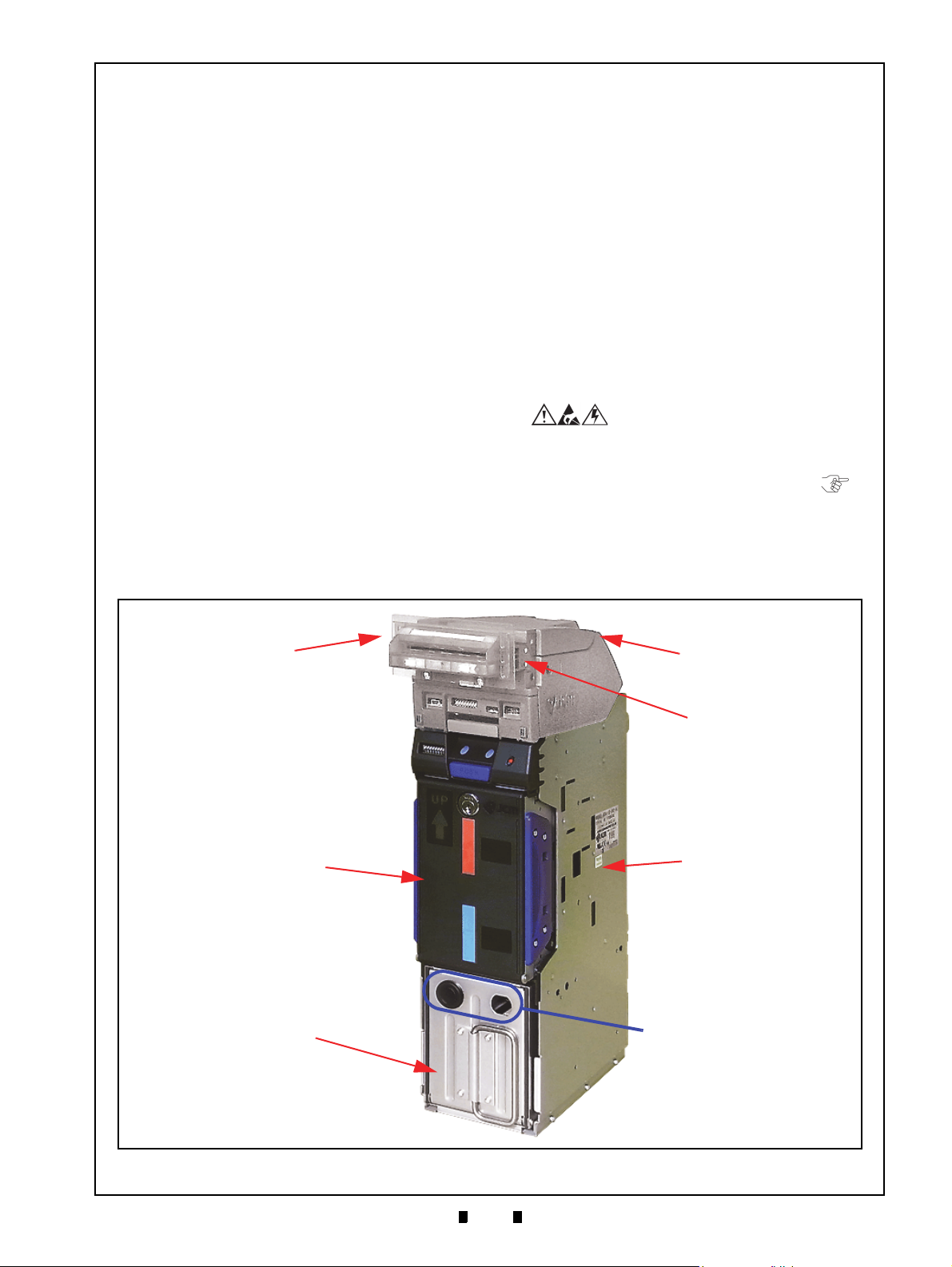
Figure 1-1 iPRO-RC Unit Assembly
iPRO-RC Unit Assembly
Figure 1-1 iPRO-RC Unit Assembly
O
PTIONAL BEZEL
A
SSEMBLY
I
PRO V
ALIDATION
A
SSEMBLY
I
PRO-RC
F
RAME UNIT
I
PRO-RC R
ECYCLER
A
SSEMBLY
I
PRO-RC C
ASH BOX
A
SSEMBLY
(NOT I
NCLUDED
)
NOTE: Cash Box Locks are
Provided Selection
an Optional User
(NOT I
NCLUDED
)
B
EZEL SPACER
(B
EHIND BEZEL
)
Banknote Recycler
Section 1
Description
This section provides a general overview of the
iPRO-RC™ Series Banknote Recycler (iPRO-100SH2-RC; iPRO-RC™) Unit Assembly pictured in
Figure 1-1. This first section is designed to help
you navigate through this guide with ease, and
provides the following information:
• iPRO-RC™ Unit Assembly
• Model Descriptions
• Precautions
• Primary Features
• Component Names
• Specifications
• Unit Dimensions
• Technical Contact Information.
In order to make operation of this device easier and
make navigation within this manual simpler, the
following illustrations were used within the text:
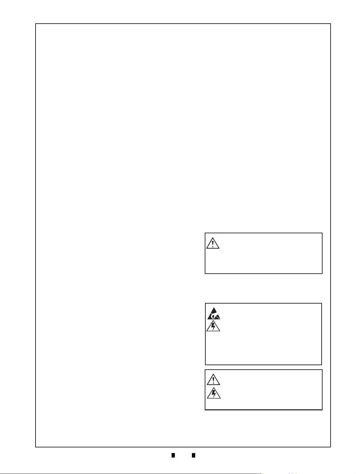
• Safety Instructions, which need to be
observed in order to protect the operators and
equipment, have been written in Bold text and
have been given the following pictographs:
• Special Notes, which affect the use of the
Banknote Recycler have been written in italic
text and have been given the pictograph:
• Steps, requiring the operator to perform
specific actions are given sequential numbers
(1., 2., 3., etc).
P/N 960-000164R_Rev. 3 {EDP #213631} © 2018, JAPAN CASH MACHINE CO., LTD.
Page 18
1-2
Section 1 iPRO-RC™ Series Banknote Recycler General Information
0 = None
1 = Width Guide 62 (Gray)
2 = Width Guide 67 (Red)
3 = Width Guide 72 (Blue)
0 = None
1 = Width Guide 62 (Gray)
2 = Width Guide 67 (Red)
3 = Width Guide 72 (Blue)
0 = None
1 = Length Guide 120 (Gray)
2 = Length Guide 127 (Red)
3 = Length Guide 133 (Blue)
4 = Length Guide 140 (Orange)
5 = Length Guide 147 (Green)
6 = Length Guide 152 (Black)
7 = Length Guide 158 (Black)
0 = None
1 = Length Guide 120 (Gray)
2 = Length Guide 127 (Red)
3 = Length Guide 133 (Blue)
4 = Length Guide 140 (Orange)
5 = Length Guide 147 (Green)
6 = Length Guide 152 (Black)
7 = Length Guide 158 (Black)
Figure 1-2 Precautionary Symbols
Type 1 Type 2 Type 3
Figure 1-2 Precautionary Symbols
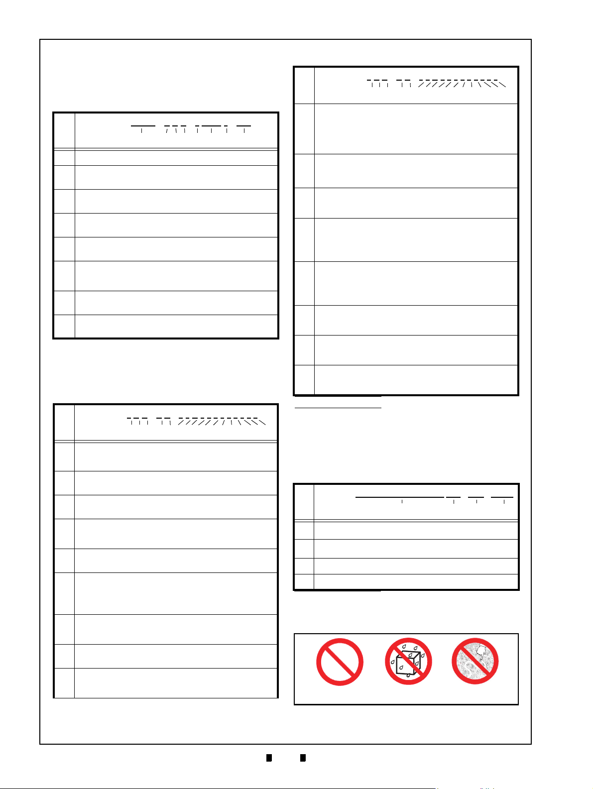
Model Descriptions
Table 1-1 lists the Product Model Number
descriptions.
Table 1-1 iPRO-RC Model Number Specifications
Model: iPRO
No.
No.
(1)
Product Series Name
Validation Sensor
(2)
1 = Standard (World Wide)
CPU Circuit Board
(3)
0 = Standard
Transport Unit Type
(4)
0 = Standard (World Wide)
Option Unit (Input Section)
(5)
none = Standard
Stacker Type
(6)
SH2 = Horizontal Down (82mm Specification)
SS = Vertical Down (Large Cash Box)
Box Access
(7)
None = Front Access (Standard)
Recycler Function
(8)
RC = Recyclable
o
(1) (2) (3)(4) (5) (6) (7) (8)
Type Descriptions
Table 1-2 lists the Product Type Number
Descriptions.
Table 1-2 iPRO-RC Type Specifications
Type: *
No.
No.o (1,2,3) (4,5) (6,7,8,9,10,11,12,13,14,15,16,17)
Cash Box Capacity
(1)
4 = 400 Notes (New Banknote)
8 = 800 Notes (New Banknote)
Cash Box Type
(2)
0 = Standard
Cash Box Handle
(3)
0 = Standard
Transport Section
(4)
0 = Standard
1 = OEM
Transport Cover
(5)
0 = Standard (Black)
Optional Bezel
0 = None
(6)
1 = Black/Green LED (UBA/iPRO Standard Bezel 85)
2 = Blue/Blue LED (UBA/iPRO Standard Bezel 85)
A = Blue/Blue (2-Line) (UBA/iPRO Standard Bezel 85)
Bezel Spacer
(7)
0 = No
1 = Yes
Optional Power Circuit Board
(8)
1 = Standard (Power Board Featured)
Input/Output Signal
(9)
P = Photo-Coupler Isolation
R = RS232C
0 0 - 0 0 - * * 1 * * * * * * * * *
- 1 0 0 - * SH2 * - RC
Table 1-2 iPRO-RC Type Specifications
Type: *
0 0 - 0 0 - * * 1 * * * * * * * * *
No.
No.o (1,2,3) (4,5) (6,7,8,9,10,11,12,13,14,15,16,17)
External Communication Harness
0 = None
(10)
1 = Standard (with Power Harness)
2 = USB I/F Harness (with Power Harness)
3 = OEM (3441-05-03)
4 = OEM (3441-05-10)
RC1 Recycler Unit Banknote Width Guide
(11)
RC2 Recycler Unit Banknote Width Guide*
(12)
*
†
RC1 Recycler Unit Banknote Length Guide*
(13)
RC2 Recycler Unit Banknote Length Guide*
(14)
Lock Unit
(15)
0 = No (without Lock)
1 = Yes (with Lock)
Anti-Static (Option)
(16)
0 = No (without Anti-Static Sheets)
1 = Yes (with Anti-Static Sheets)
Optional Cash Box Fastener
(17)
0 = None
1 = Thumb Twist Lock Fastener for the Cash Box
*. Contact each region’s local JCM representative for details.
†. Refer to each Country’s “Software Information Sheet”.
Software Descriptions
Table 1-3 lists the Software Number
Specifications.
Table 1-3 iPRO-RC Software No. Specifications
Software: iPRO-100-(*)SH2(*)-RC * * * - 0 * * - V * .**
No.
No.o (A) (B) (C) (D)
(A)
Software Model Name
(B)
Denomination (Country)
(C)
Interface Protocol Name
(D)
Software Version
*. The Country Code is indicated by three (3) Alphabetical Characters
following the JIS Country Standard abbreviation.
*
Precautions
P/N 960-000164R_Rev. 3 {EDP #213631} © 2018, JAPAN CASH MACHINE CO., LTD.
Page 19
1-3
General Information iPRO-RC™ Series Banknote Recycler Section 1
Caution: DO NOT use any alcohol,
solvents, abrasive cleaning agents,
or citrus-based cleaners that can
damage the plastic surface of the
device when cleaning it.
Caution: Make Interface Harness
connections to the Host Machine
shorter than 9.84 Feet (3 Meters) in
length. Cut off all unused portions
of the Interface Harness wiring to
avoid static electrical effects or
short circuit possibilities that
could cause damage to the Unit.
WARNING: This Unit is designed
for use with a Current limiting
Power Source! Design the Host
Cabinet space to meet all local
related safety standards.
The Figure 1-2 symbols are defined as follows:
1. (Typ e 1 ) Do not insert a torn, folded, or wet
Banknote into the Unit, as this action may cause a
Banknote jam inside the Unit.
Typ e 2 ) Do not expose the Recycler Unit to
2. (
water or any other liquids. The Unit contains
several precision electronic devices
damaged if water or other liquids are sprayed or
spilled into the Unit.
Typ e 3 ) Do not install the Unit into a dusty
3. (
environment. Dust may affect and degrade the
Recycler’s performance.
User Cautions
Careful measures are taken in the design of this
product to ensure its quality; however, the following cautions should be read and understood by all
users in order to confirm safe operation.
I
NSTALLATION CAUTIONS
The Installation Cautions are defined as follows:
1. Do not allow the Unit to endure or operate at a
high temperature, in high humidity and/or in a
dusty environment.
2. Do not install the Unit
sive vibration or shock are present.
3. The Unit is not designed for outside installation.
4. Avoid exposing the Unit to direct Sunlight and/or
5. Ensure that the Host Machine is designed for
6. When installing the equipment, connect the
7. If an unused Interface
8. Because this equipment is a component product,
9. Do not operate the iPRO-R
10. This Unit is designed to use a current limiting
M
OUNTING
Methods for Mounting, Dismounting, and Transporting the Unit are as follows:
1. Be sure to turn the Power OFF to the iPRO-RC™
P/N 960-000164R_Rev. 3 {EDP #213631} © 2018, JAPAN CASH MACHINE CO., LTD.
ure that the Host Machine contains enough
Be s
protection to avoid wet or dusty conditions when
installing in either an indoor or open-air space.
candescent Lamp illumination having a
In
Gradient Angle of 15 Degrees or more, and an
illumination index of 3000 Lux or less.
daily operational access for maintenance
and/or clearing a Banknote jam.
Frame Housing
Machine.
Harness off short to avoid attracting static electricity or a short circuit possibility that may cause
dam
age to the Unit.
close the Ho
Cash Box and/or the Recycler Unit’s door is open.
Personal injury may occur.
Power Source. Be s
cabinet material design meets local safety standards.
, D
Unit before mounting or removing the Recycler
Unit from its permanent location. Attaching or
unplugging Connector Plugs from their Receptacles while the Power is ON may damage the Unit.
st Machine’s door before using it.
ISMOUNTING
that may be
into an area where exces-
to the Frame Ground of the Host
Harness exists, cut the
C™ Unit while the
ure that the Host Machine’s
& T
RANSPORTATION
2. When reassembling a Unit’
each part is replaced in its correct location.
3. Be sure to carry the Unit by both hands when
transportin
cause personal injury if the Unit accidentally
becomes disassembled and falls away from the
Frame housing.
4. Be careful not to use exc
on the Recycler Unit, or subject it to excessive
vibration during transportation.
5. Check that the iPRO™ T
not drop off the Unit Frame while pulling the
Recycler forward from the Frame.
g it. Holding the Unit by one hand may
s Section, ensure that
essive outside pressure
ransport Section does
Preventive Maintenance
The Preventive Maintenance requirements are
defined as follows:
1. Be sure to turn the Power OFF before beginning a
maintenance procedure. The equipment produces
improper operating signals while in maintenance
mode that may cause personal injury.
2. When closing the Recycler Unit, ensure all service door locks click into place.
3. If the iPRO™ Validator Section is dirty due to
st, foreign objects or other such debris adhering
du
to it, the Banknote acceptance rate will degrade.
Clean the Transport Unit once a month to keep its
performance stable.
4. Use a soft, lint-free cloth,
pressed air spray to clean dust and debris from the
Banknote
5. Do not redesign or disassemble the Recycler Unit.
Unauthorized us
personnel, or use outside the original manufacturer’s intent for operation voids the warranty.
path and inside areas of the Recycler.
e by inadequately trained
cotton swab or a com-
Page 20
1-4
Section 1 iPRO-RC™ Series Banknote Recycler General Information
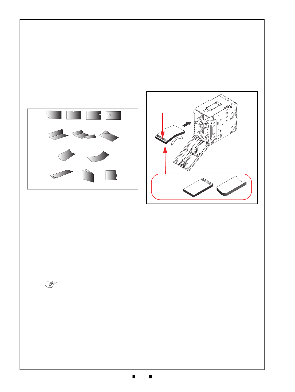
Figure 1-3 Unacceptable Banknotes
Figure 1-3 Unacceptable Banknotes
Damaged Banknotes
Wrinkled Banknotes
Curled Banknotes
Folded or Partial Banknotes
NOTE: Do not insert more than the
above recommended recyclable
Banknotes.
Figure 1-4 Banknote Storage Insertion Cau-
tions
Figure 1-4 Banknote Storage Insertion Cautions
x
Adjust shapes
before restoring
recyclable
Banknotes.
x
a
Hologram
End
aaa
b
Banknote Fitness Requirements
The following Banknote types may not validate
correctly, or can cause a Banknote jam and/or damage to the Unit’s Transport path. Banknotes exhibiting the conditions listed below and illustrated in
Figure 1-3 should be avoided:
• Torn
• Having excessive folds
• Dirty
• Wet
• Having excessive wrinkles
• Adhering foreign objects and/or oil
7. Make sure the denomination of each Banknote
bundle ins
direction.
8. Make sure the Banknote bundle inserted is of the
same deno
when restoring by hand.
9. Insert the Banknotes being recycled into the
Recycler Unit’
reaches the very back of the Bin.
10. Verify that the bottom Note of a Banknote bundle
not curled or folded when inserting the Bank-
is
note bundle into a Recycler Unit’s Bin.
erted is correctly placed in the same
mination and from the same Country
s Bins carefully until the bundle
Banknote Storage Requirements
The following conditions are required when placing
Banknotes directly into the Recycler Unit’s Bins.
1. Replace the minimum Banknote count as required
for Recycler initialization, so the Banknotes will
be available for use during a standard recycle
function.
• The maximum number of recyclable Banknotes
in a Recycler
Unit’s Bin should be:
– Approximately 100 Notes if the Banknotes are
all new
– Approximately 70 Notes if the Banknotes are
a mixed Street Grade level.
2. Do not use any Banknotes indicated in Figure 1-3
“Unacceptable Banknotes ” shown on this page.
3. Make one edge of the Banknote bundle smooth.
4. Verify that no curled or folded Banknotes
5. Before placing Banknotes into the Recycler Bins
6. Verify that the Holograp
ally new Notes), Flip-over and Fan-Flip
(especi
the Banknote bundle; then curve the middle of the
Banknote bundle to form a downward angled
structure (Figure 1-4 a).
hic image portion of a
Banknote is always at the front end of the insertion direction (Figure 1-4 b).
exist.
Primary Features
The iPRO-RC™ Series Banknote Recycler
contains the following primary features:
• Allows a high capacity, compact size,
Recycling Unit available for two (2) different
Banknote denominations
• The Friction Roller System eases operation and
maintenance of the Recycler Unit
• The Automatic Centering Mechanism allows
the Unit to read Banknotes ranging from 62mm
to 82mm in width, and a maximum of 158mm
in length. It will automatically center
Banknotes inserted at an angle to help improve
the acceptance rate
• A secure Recycler Unit containing a Key Lock
is composed of durable, impact-resistant
plastic construction to assure safe and secure
cash handling.
• The JCM patented Anti-Pullback Mechanism
provides powerful protection against Banknote
stringing operations.
P/N 960-000164R_Rev. 3 {EDP #213631} © 2018, JAPAN CASH MACHINE CO., LTD.
Page 21
1-5
General Information iPRO-RC™ Series Banknote Recycler Section 1
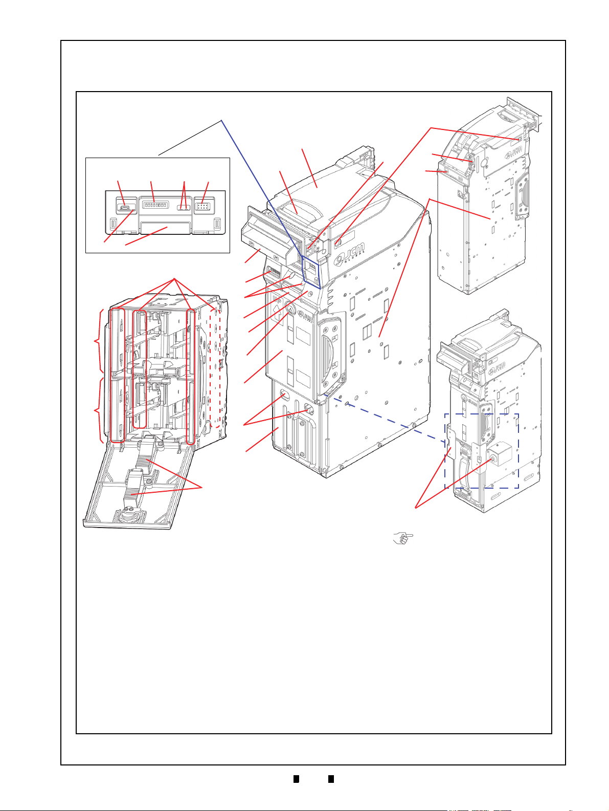
Figure 1-5 iPRO-RC Component Names
Figure 1-5 iPRO-RC Component Names
A.iPRO Transport Unit
(User Supplied)
B.iPRO Unit Upper Guide Access Lever
C.Front Panel Access
1.USB mini-B Type Receptacle
(for performing
Software downloads and adjustments)
2.8 Position DIP Switch Block
3.iPRO Transport Unit LEDs (Green & Red)
4.Front Bezel Receptacle (for the Optional Bezel
Assembly Plug)
5.Centering LED
6.Transport Unit Release Lever
D.RC Unit DIP Switch Block
E.RC Unit LEDs
(Green, Red & Yellow)
F. Recycler Unit Release Pushbutton
G.Restore Pushbutton (for moving Banknotes from the
Recycler Unit into the Cash Box)
H.Recycler Unit Lock (Supplied with Key)
I. Recycler Unit
J. Cash Box Lock Holes
(Locks are User Supplied
Options)
K.Cash Box
L. Bezel Accessory
(One of 3 Options Available)
M.Bezel Spacer
N.Centering Guide Release Port
O.Interface Connector
(Connects to the Host Machine)
P. Housing Frame
Q.RC1-Bin Assembly Banknote Space
R.RC2-Bin Assembly Banknote Space
S.Banknote Width Guide
T. Banknote Length Guide
U.Power Connector
V.Optional Lock Unit
(Right or Left side)
A
B
E
G
H
I
L
M
D
F
N
J
K
12354
C: Front Panel Access
6
Recycler Unit Assembly
Rear Side
Front Side
Optional Lock
O
U
P
Q
R
T
C
S
V
NOTE: The Optional Lock is
available for installation on
either the right or left side of an
iPRO-RC Unit.
Component Names
Figure 1-5 illustrates the iPRO-RC™ component names and locations.
P/N 960-000164R_Rev. 3 {EDP #213631} © 2018, JAPAN CASH MACHINE CO., LTD.
Page 22
1-6
Section 1 iPRO-RC™ Series Banknote Recycler General Information
Specifications
Technical Specifications
Table 1-4 iPRO-RC Technical Specifications
98% or greater
The following Banknote Types are excluded:
Acceptance Rate:
a) Banknotes with excess or poor magnetism or unclear graphics
b) Double (dual) Banknotes
c) Worn, dirty, wet, stained, torn or excessively wrinkled Banknotes
d) Banknotes having folded corners or edges
e) Banknotes having the wrong cut dimensions or a printing displacement.
Recycler Unit
• Length: 120-158mm (4.72-6.22 in.)
Banknote Types Accepted†:
• Width: 62-82mm (2.44-3.22 in.)
Cash Box
• Length: 120-170mm (4.72-6.69 in.)
• Width: 62-82mm (2.44-3.22 in.)
Standard Specification
a) Interleaved Barcode Read: 2 of 5
b) Narrow Bar Width: 0.5mm-0.6mm (0.019-0.023 in.)
Barcode Coupon**:
Insertion Direction:
c) Wide Bar to Narrow Bar ratio = 3:1
d) Characters: 18 Characters
e) Print Position: Middle (Divides a Coupon equally to the left, right, top and
bottom of the Coupon’s center line)
f) Print Width: Wider than 10mm (0.39 in.)
Banknote:
Barcode Coupon: Two-way (with Barcode Surface Facing Upward)
From Banknote insertion to Vend signal output:
• Approximately 2 seconds
From Banknote insertion to stacking operation completion:
• Approximately 5 seconds (to Recycler Unit)
Processing Speed††:
• Approximately 6 seconds (to Cash Box)
From dispense beginning to dispensing operation completion:
• Approximately 3 seconds
From retrieve beginning to retrieving operation completion:
• Approximately 7 seconds
Escrow: 1 Note
Transport Unit: Two Single-Color LEDs
Diagnostic Indicators:
Cash Box‡‡:
Cash Box Capacity:
Recycler Unit: Key Lockable, 2 Denomination Integral Recycler (Friction Roller System)
Recycler Unit Capacity: 100 Notes (New Banknotes Only)
Recycle Unit Storage Method:
Interfaces:
*. Refer to the “Software Information Sheet” for each Country’s Acceptance Rate parameters.
†. Banknote size widths are limited by the specific Guide Types inserted.
‡. Contact each region’s local JCM representative if the Banknote length is over 165mm (6.49 in.).
**.Refer to the specific Country’s Barcode Coupon Specification for more details.
††.Excludes the time lag associated with Host Communication (Power Supply: +24V DC, Temperature: 25º C ±5º C).
‡‡.Cash Box Lock(s) and Key(s) are provided by User (2 Key Hole Caps are fitted in place to cover existing holes when shipped).
RC Unit: Two Tri-Color LEDs (Red/Green/Yellow)
Centering Home Position Indicator: LED (Red)
Steel: Secure Type (WBA-SH2 Cash Box Design)
Plastic: Secure Type (UBA/iPRO Large Cash Box Design)
400 Notes
800 Notes (New Banknotes Only) (UBA/iPRO Large Cash Box Design)
Stores Banknotes from the Acceptor
Stores Banknotes directly
USB (USB Specification Rev.2.0/Full Speed Transmission 12Mbps)
Photo-Coupler Isolation, TTL & RS232C
*
‡
Refer to the specific Country’s “Software Information Sheet”
(Red/Green)
(New Banknotes Only) (WBA-SH2 Cash Box Design)
(Recommended)
P/N 960-000164R_Rev. 3 {EDP #213631} © 2018, JAPAN CASH MACHINE CO., LTD.
Page 23
1-7
General Information iPRO-RC™ Series Banknote Recycler Section 1
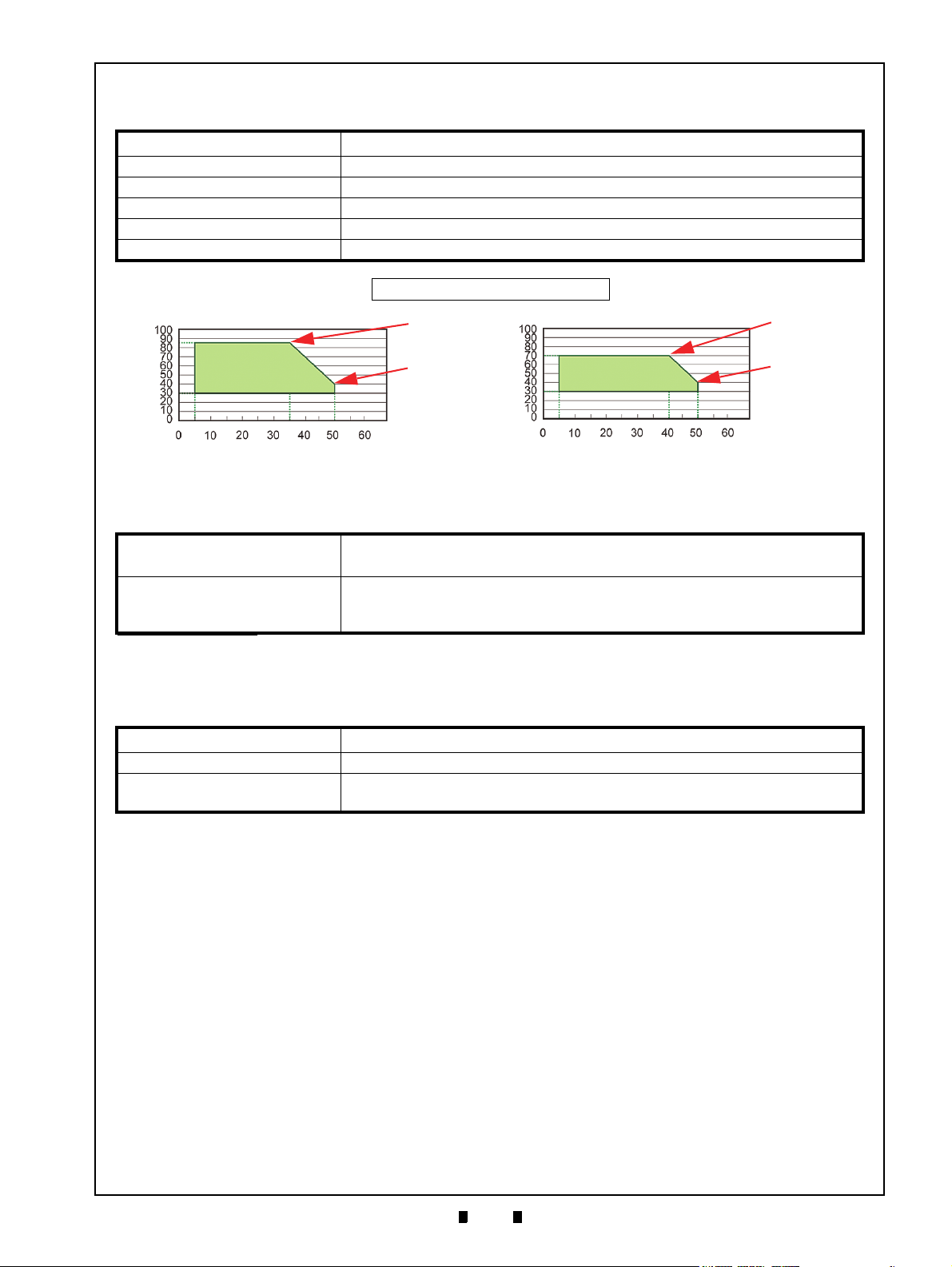
Hydrothermal Condition Table
[°C]
[RH%]
35°C/85%
50°C/40%
[°C]
[RH%]
40°C/70%
50°C/40%
Normal Banknote
Polymer Banknote
Allowable Operating
Temperature and
Humidity Range
Allowable Operating
Temperature and
Humidity Range
Environmental Specifications
Table 1-5 iPRO-RC Environmental Specifications
Operating Temperature: 5ºC to +50ºC (41ºF to 122ºF)
Storage Temperature: -20ºC to +60ºC (-4ºF to 140ºF)
Relative Operating Humidity: 30% to 85% RH (non-condensing)
Relative Storage Humidity: 30% to 85% RH (non-condensing)
Visible Light Sensitivity: Avoid contact with direct Sunlight
Installation: Indoors Only
Electrical Specifications
Table 1-6 iPRO-RC Electrical S
pecifications
Supply Voltage
*
:
24V DC (±5%) (Greater than 3.5A Recommended)
(Use a Current Limiting Power Source)
Standby: 230mA
Current Consumption:
Operation: 1.5A
Peak: 2.5A
*. Use a Limited Power Source.
Structural Specifications
Table 1-7 iP
Weight Empty: Approximately 9kg (19.8lbs)
Mounting: Horizontal
Outside Dimensions:
Refer to Figure 1-6 “iPRO-RC Banknote Recycler Standard Unit with
Bezel Outside Dimensions” on page 1-8 of this Service Manual Section.
RO-RC Structural Specifications
P/N 960-000164R_Rev. 3 {EDP #213631} © 2018, JAPAN CASH MACHINE CO., LTD.
Page 24
1-8
Section 1 iPRO-RC™ Series Banknote Recycler General Information
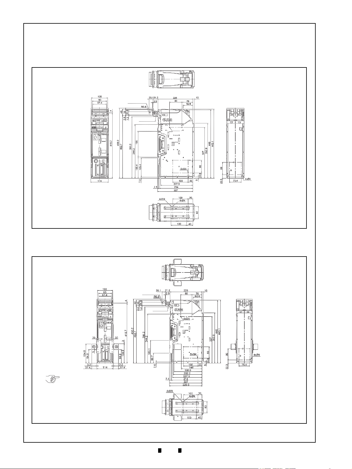
Figure 1-6 iPRO-RC Banknote Recycler Stan-
dard Unit with Bezel Outside Dimensions
Figure 1-6 iPRO-RC Banknote Recycler Standard Unit with Bezel Outside Dimensions
UBA/iPRO Bezel Unit
Bezel Spacer
MAX DEPTH7mm
NOTE: All dimension are in millimeters
MAX DEPTH7mm
Figure 1-7 iPRO-RC Banknote Recycler Stan-
dard Unit with Bezel, Lock Unit and Outside
Dimensions
Figure 1-7 iPRO-RC Banknote Recycler Standard Unit with Bezel, Lock Unit and Outside Dimensions
UBA/iPRO Bezel Unit
Bezel Spacer
MAX DEPTH7mm
NOTE: The Lock Unit is available
for installation on either the right
or left side of the Unit.
NOTE: All dimension are in millimeters
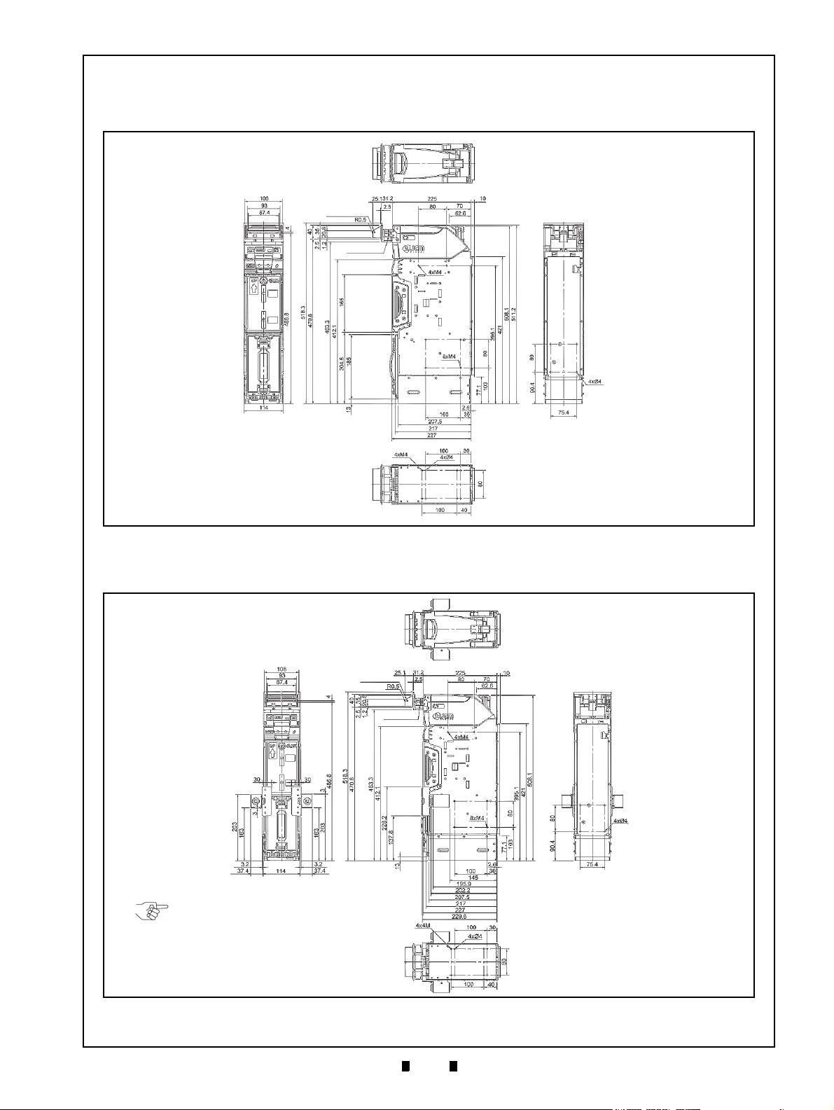
Unit Dimensions
Entire Unit Outside Dimensions
Figure 1-6 illustrates the iPRO-RC™ Unit with the Bezel, Bezel Spacer and 400 Note Cash Box outside
dimensions.
Figure 1-7 illustrates the iPRO-RC™ Unit with the Bezel, Bezel Spacer, Lock Unit and 400 Note Cash
Box outside dimensions.
P/N 960-000164R_Rev. 3 {EDP #213631} © 2018, JAPAN CASH MACHINE CO., LTD.
Page 25
1-9
General Information iPRO-RC™ Series Banknote Recycler Section 1
Figure 1-8 iPRO-RC Banknote Recycler Stan-
dard Unit with Bezel Outside Dimensions
Figure 1-8 iPRO-RC Banknote Recycler Standard Unit with Bezel Outside Dimensions
UBA/iPRO Bezel Unit
Bezel Spacer
MAX DEPTH7mm
MAX DEPTH7mm
NOTE: All dimension are in millimeters
Figure 1-9 iPRO-RC Banknote Recycler Stan-
dard Unit with Bezel, Lock Unit and Outside
Dimensions
Figure 1-9 iPRO-RC Banknote Recycler Standard Unit with Bezel, Lock Unit and Outside Dimensions
UBA/iPRO Bezel Unit
Bezel Spacer
MAX DEPTH7mm
NOTE: The Lock Unit is available
for installation on either the right or
left side of the Unit.
NOTE: All dimension are in millimeters
MAX DEPTH7mm
Entire Unit Outside Dimensions (Continued)
Figure 1-8 illustrates the iPRO-RC™ Unit with the Bezel, Bezel Spacer and 800 Note Cash Box outside
dimensions.
Figure 1-9 illustrates the iPRO-RC™ Unit with the Bezel, Bezel Spacer, Lock Unit and 800 Note Cash
Box outside dimensions.
P/N 960-000164R_Rev. 3 {EDP #213631} © 2018, JAPAN CASH MACHINE CO., LTD.
Page 26

1-10
Section 1 iPRO-RC™ Series Banknote Recycler General Information
Technical Contact Information
To obtain further technical information regarding the iPRO-RC Twin™ device, please contact the nearest
location listed below:
Americas
JCM A
MERICAN
Phone: +1-702-651-0000
Fax: +1-702-644-5512
925 Pilot Road, Las Vegas, NV 89119
E-mail: support@jcmglobal.com
Europe, Middle East, Africa & Russia
JCM E
UROPE GMB
H
Phone: +49-211-530-645-60
Fax: +49-211-530-645-65
Mündelheimer Weg 60
D-40472 Düsseldorf Germany
E-mail: support@jcmglobal.eu
UK & Ireland
JCM E
UROPE
(UK O
FFICE
)
Phone: +44 (0) 190-837-7331
Fax: +44 (0) 190-837-7834
Unit B, Third Avenue
Denbigh West Business Park
Bletchley, Milton Keynes,
Buckinghamshire MK1 1DH, UK
Asia and Oceania
JCM G
JAPAN CASH MACHINE CO., LTD.(HQ)
The JCM Website for all locations is:
http://www.jcmglobal.com
OLD
(HK) LTD.
Phone: +852-2429-7187
Fax: +852-2929-7003
Unit 1-7, 3/F., Favor Industrial Centre
2-6 Kin Hong Street, Kwai Chung,
N.T. Hong Kong
E-mail: asiasupport@jcmglobal.com
Phone: +81-6-6703-8400
Fax: +81-6-6707-0348
2-3-15, Nishiwaki, Hirano-ku, Osaka 547-0035
JAP
AN
E-mail: Shohin@jcm-hq.co.jp
E-mail: support@jcmglobal.eu
P/N 960-000164R_Rev. 3 {EDP #213631} © 2018, JAPAN CASH MACHINE CO., LTD.
Page 27
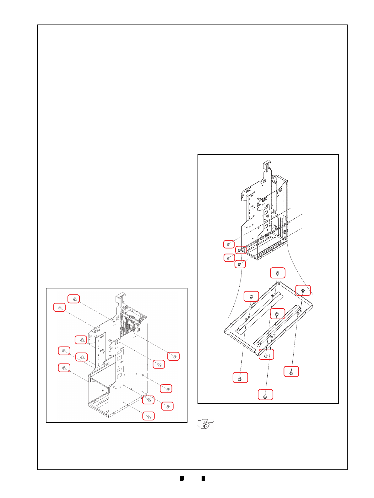
2-1
iPRO-RC™ Series
2 INSTALLATION
Figure 2-1 M4 Screws Locations (Right/Left)
Figure 2-1 M4 Screws Locations (Right/Left)
Figure 2-2 M4 Screws Locations (Rear &
Bottom)
Figure 2-2 M4 Screws Locations (Rear & Bottom)
a
1
a
3
a
2
a
4
b
1
b
3
b
2
b
4
c
3
c
2
c
4
c
1
NOTE: Choose two (2) of the five (5)
installation configuration sides shown, and
bolt the correct number of M4 Screws firmly
in place. When bolting the Screws from the
outside, the maximum length of each M4
Screw must be less than 7mm long.
Banknote Recycler
Section 2
This section provides installation and operating
instructions for the iPRO-RC™ Series Banknote
Recycler Unit (iPRO-100-SH2-RC; iPRO-RC™).
The information within contains the
following features:
• Installation Procedure
• Cable Interconnection
• DIP Switch Configuration
• Switch Configuration
• Connector Pin Assignments
• Preventive Maintenance
• Clearing a Banknote Jam
• Cleaning Procedure
• Standard Interface Circuit Schematics
• Operational Flowchart
Installation Procedure
Holes are provided in each Frame Unit to accommodate mounting the iPRO-RC™ during installation. Select and perform the following steps
required to install the iPRO-RC™ Unit:
1. When a side mounting configuration is preferred,
bolt the left or right side of the iPRO-RC™ Frame
into its intended location using six (6) M4 Screws
from either side of the Frame (Figure 2-1).
3. When a bottom mounting configuration is preferred, bolt the inside or outside of the
iPRO-RC
using four (4) M4 Phillips Head Screws. To bolt
the Frame down from the inside, place the screws
in the four un-threaded holes located inside the
Frame (Figure 2-2 b
down from the outside using th
Stud Insert holes located on the outside of the
Frame (Figure 2-2 c
™ Frame into its intended location
to b4); or bolt the Frame
1
to c4).
1
e four (4) threaded
2. When a rear mounting configu
bolt the inside back of the iPRO-RC
its intended location using four (4) M4 Phillips
Head Screws (Figure 2-2 a
P/N 960-000164R_Rev. 3 {EDP #213631} © 2018, JAPAN CASH MACHINE CO., LTD.
1
ration is preferred,
™ Frame into
through a4).
Page 28
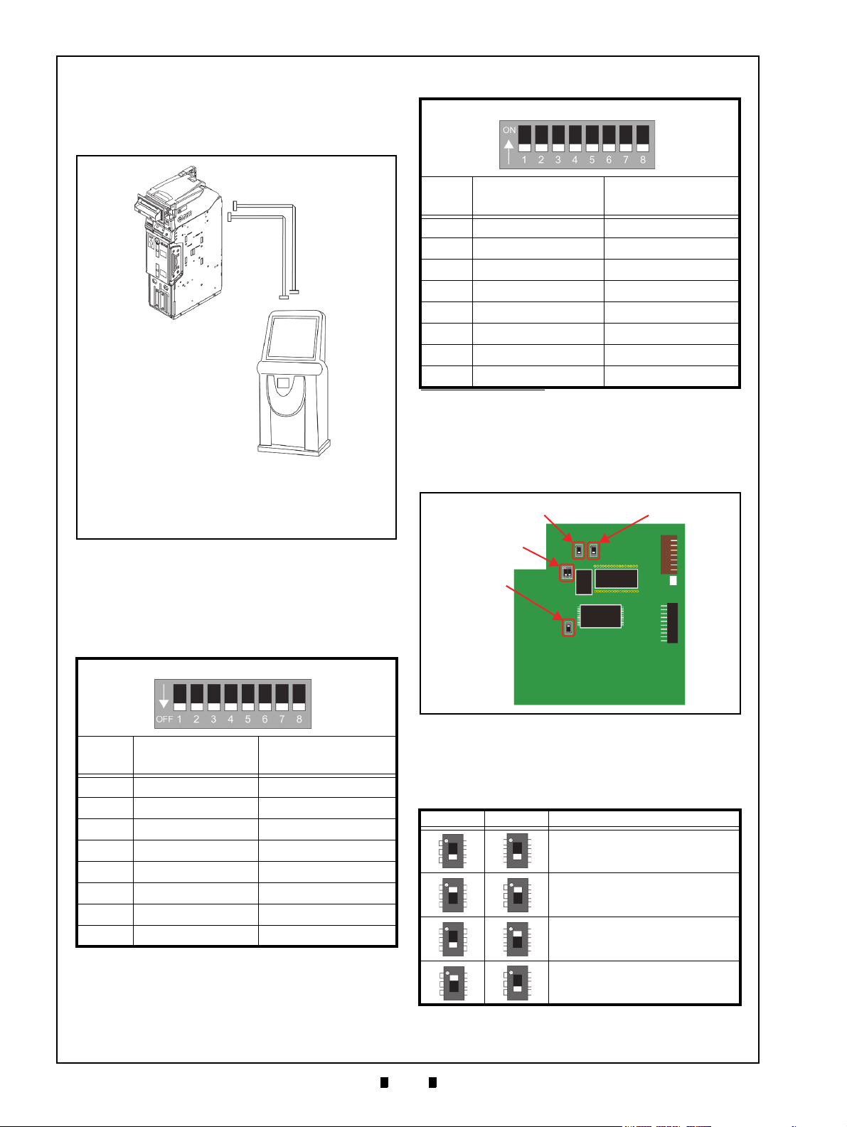
2-2
Section 2 iPRO-RC™ Series Banknote Recycler Installation
Figure 2-3 Cable Interconnection
Figure 2-3 Cable Interconnection
a
b
c
a) iPRO-RC™ Unit
b) Interface Connector
c) Interconnecting Harness
d) Host Machine (Game Machine, Kiosk, etc.)
e) Power Connection Harness
e
d
Figure 2-4 CPU Board Switch Locations
Figure 2-4 CPU Board Switch Locations
Switch #3
Switch #5
Switch #4
Switch #2
Cable Interconnection
Figure 2-3 illustrates the Cable interconnection
requirements between the iPRO-RC™ and a Host
Machine.
Table 2-2 iPRO-RC Unit DIP Switch Settings
iPRO-RC Unit DIP Switches
Switch
No.
1 Reserved Reserved
2 Reserved Reserved
3 Reserved Reserved
4 Reserved Reserved
5 Reserved Reserved
6 Reserved Reserved
7 Reserved Reserved
8 Reserved Reserved
*. Refer to each Country’s “Software Information Sheet” for making the
proper Switch settings.
Switch ON Switch OFF
*
Switch Configuration
The CPU Circuit Board contains four (4) DIP
Switches on the Circuit Board (Figure 2-4).
DIP Switch Configuration
This section provides the denomination DIP Switch
Block settings for the iPRO-RC
Table 2-1 iPRO Transport Unit DIP Switch Settings
iPRO Transport Unit DIP Switches
Switch
No.
1 VEND 1 INHIBIT VEND 1 ACCEPT
2 VEND 2 INHIBIT VEND 2 ACCEPT
3 VEND 3 INHIBIT VEND 3 ACCEPT
4 VEND 4 INHIBIT VEND 4 ACCEPT
5 VEND 5 INHIBIT VEND 5 ACCEPT
6 VEND 6 INHIBIT VEND 6 ACCEPT
7 VEND 7 INHIBIT VEND 7 ACCEPT
8OFF OFF
Switch ON Switch OFF
™ Unit.
DIP Switches identify an RS232C, Photo-Coupler,
or ccTalk configuration selection (Table 2-3).
Table 2-3 CPU Board Switch Configurations
Switch 5 Switch 3 Signal Name
RS232C
Photo-Coupler Isolation
cc-Talk
Reserved
P/N 960-000164R_Rev. 3 {EDP #213631} © 2018, JAPAN CASH MACHINE CO., LTD.
Page 29

2-3
Installation iPRO-RC™ Series Banknote Recycler Section 2
NOTE: Refer to the “iPRO Service Manual”
for details regarding the DIP Switch
Configurations when using the iPRO Unit
without a Recycler Unit.
DIP Switches also select the ICB or Recycler
options (Table 2-4).
Table 2-4 RC Selection Switch Configuration
Switch 2 Switch 4 Description
iPRO™ Unit without an RC Unit
(When the IC
iPRO™ Unit without an RC Unit
(When the IC
Board is NOT installed)
iPRO™ Unit using an RC Unit
B Expansion Circuit
Board is installed)
B Expansion Circuit
P/N 960-000164R_Rev. 3 {EDP #213631} © 2018, JAPAN CASH MACHINE CO., LTD.
Page 30

2-4
Section 2 iPRO-RC™ Series Banknote Recycler Installation
Connector Pin Assignments
Table 2-5 lists the USB Interface Connector Pin Assignments.
Table 2-5 USB Interface Connection Pin Assignments
Socket (Transport Unit Side): DRA-20PC-FO (JAE)
Contact (Transport Unit Side): D02-22-26P-10000 (JAE)
Contact (Frame Side): D02-22-26S-10000 (JAE)/D02-22-22S-10000 (JAE) (Terminal# 3, 13)
Pin No. Signal Name
1-- -Reserved
2-- -Reserved
3 M.RES IN Acceptor Hard Reset Signal Line
4 NC - No Connection
5-- -Reserved
6 NC - No Connection
7 NC - No Connection
8 Vbus IN USB Communication Vbus Signal Line (+5V DC)
9 -DATA IN/OUT USB Communication Input/Output Signal Line
10 +DATA IN/OUT USB Communication Input/Output Signal Line
11 -- - Reserved
12 GND (USB) - USB Communication Ground (0V DC)
13 NC - No Connection
14 LED (Power) - LED Drive Line (Anode)
15 -- - Reserved
16 NC - No Connection
17 -- - Reserved
18 LED - LED Drive Line (Cathode)
19 NC - No Connection
20 -- - Reserved
*. I/O (input/output) is the terminal as viewed from the Banknote Recycler’s backside.
Socket (Frame Side): DRA-20SC-FO (JAE)
Recommended Wires: Slit Wire UL1061 AWG #26
I/O
*
Function
P/N 960-000164R_Rev. 3 {EDP #213631} © 2018, JAPAN CASH MACHINE CO., LTD.
Page 31

2-5
Installation iPRO-RC™ Series Banknote Recycler Section 2
Connector Pin Assignments (Continued)
Table 2-6 lists the Photo Coupler Interface Connector Pin Assignments.
Table 2-6 Photo Coupler Interface Connection Pin Assignments
Socket (Transport Unit Side): DRA-20PC-FO (JAE)
Contact (Transport Unit Side): D02-22-26P-10000 (JAE)
Contact (Frame Side): D02-22-26S-10000 (JAE)/D02-22-22S-10000 (JAE) (Terminal# 3, 13)
Pin No. Signal Name
1-- -Reserved
2-- -Reserved
3 M.RES IN Acceptor Hard Reset Signal Line
4 TXD OUT Output Signal Line from Acceptor to Host
5-- -Reserved
6 RXD IN Input Signal Line from Host to Acceptor
7 GND (I/F) - Interface Power Supply (Photo Coupler 0V DC)
8 NC - No Connection
9 NC - No Connection
10 NC - No Connection
11 -- - Reserved
12 NC - No Connection
13 NC - No Connection
14 LED (Power) - LED Drive Line (Anode)
15 -- - Reserved
16 NC - No Connection
17 -- - Reserved
18 LED - LED Drive Line (Cathode)
19 NC - No Connection
20 -- - Reserved
*. I/O (input/output) is the terminal as viewed from the Banknote Recycler’s backside.
Socket (Frame Side): DRA-20SC-FO (JAE)
Recommended Wires: Slit Wire UL1061 AWG #26
I/O
*
Function
P/N 960-000164R_Rev. 3 {EDP #213631} © 2018, JAPAN CASH MACHINE CO., LTD.
Page 32

2-6
Section 2 iPRO-RC™ Series Banknote Recycler Installation
Connector Pin Assignments (Continued)
Table 2-7 lists the RS232C Interface Connector Pin Assignments.
Table 2-7 RS232C Interface Connection Pin Assignments
Socket (Transport Unit Side): DRA-20PC-FO (JAE)
Contact (Transport Unit Side): D02-22-26P-10000 (JAE)
Contact (Frame Side): D02-22-26S-10000 (JAE)/D02-22-22S-10000 (JAE) (Terminal# 3, 13)
Pin No. Signal Name
1-- -Reserved
2-- -Reserved
3 M.RES IN Acceptor Hard Reset Signal Line
4 TXD OUT Output Signal Line from Acceptor to Host
5-- -Reserved
6 RXD IN Input Signal Line from Host to Acceptor
7 NC - No Connection
8 NC - No Connection
9 NC - No Connection
10 NC - No Connection
11 -- - Reserved
12 NC - No Connection
13 GND (I/F) - Interface Power Supply (RS232C 0V DC)
14 LED (Power) - LED Drive Line (Anode)
15 -- - Reserved
16 NC - No Connection
17 -- - Reserved
18 LED - LED Drive Line (Cathode)
19 NC - No Connection
20 -- - Reserved
*. I/O (input/output) is the terminal as viewed from the Banknote Recycler’s backside.
Socket (Frame Side): DRA-20SC-FO (JAE)
Recommended Wires: Slit Wire UL1061 AWG #26
I/O
*
Function
P/N 960-000164R_Rev. 3 {EDP #213631} © 2018, JAPAN CASH MACHINE CO., LTD.
Page 33

2-7
Installation iPRO-RC™ Series Banknote Recycler Section 2
Connector Pin Assignments (Continued)
Table 2-8 lists the ccTalk Interface Connector Pin Assignments.
Table 2-8 ccTalk Interface Connection Pin Assignments
Socket (Transport Unit Side): DRA-20PC-FO (JAE)
Contact (Transport Unit Side): D02-22-26P-10000 (JAE)
Contact (Frame Side): D02-22-26S-10000 (JAE)/D02-22-22S-10000 (JAE) (Terminal# 3, 13)
Pin No. Signal Name
1-- -Reserved
2-- -Reserved
3 M.RES IN Acceptor Hard Reset Signal Line
4 NC - No Connection
5-- -Reserved
6 NC - No Connection
7 NC - No Connection
8 NC - No Connection
9 NC - No Connection
10 NC - No Connection
11 -- - Reserved
12 NC - No Connection
13 GND (I/F) - Interface Power Supply (ccTalk 0V DC)
14 LED (Power) - LED Drive Line (Anode)
15 -- - Reserved
16 TXD OUT Output Signal Line from Acceptor to Host
17 -- - Reserved
18 LED - LED Drive Line (Cathode)
19 NC - No Connection
20 -- - Reserved
*. I/O (input/output) is the terminal as viewed from the Banknote Recycler’s backside.
Socket (Frame Side): DRA-20SC-FO (JAE)
Recommended Wires: Slit Wire UL1061 AWG #26
I/O
*
Function
P/N 960-000164R_Rev. 3 {EDP #213631} © 2018, JAPAN CASH MACHINE CO., LTD.
Page 34

2-8
Section 2 iPRO-RC™ Series Banknote Recycler Installation
Connector Pin Assignments (Continued)
Table 2-9 lists the iPRO-RC™ Power Supply Pin Assignments.
Table 2-9 Power Supply Pin Assignments
Header Type: 53426-0410 (MOLEX)
Contact Type: 50351-8100 (MOLEX)
Recommended Wires: Slit Wire UL1007 AWG #22-24
Pin No. Signal Name
1 +24V Power - +24V DC Power Supply
2 +24V Power - +24V DC Power Supply
3 GND (Power) - 0V DC Power
4 GND (Power) - 0V DC Power
*. I/O (input/output) is the terminal as viewed from the Banknote Recycler’s backside.
Housing: 51103-0400 (MOLEX)
*
I/O
Function
Connector Pin Assignments (Continued)
Table 2-10 lists the iPRO-RC™ Front Panel Bezel Interface Connection Pin Assignments.
Table 2-10 Front Panel Bezel Interface Connection Pin Assignments
Header Type: RF-H08(07)2SD-1110 (JST)
Contact Type: RF-SC2210 (JST)
Recommended Wires: Slit Wire UL1007 AWG #24-26
Pin No. Signal Name
1 NC - No Connection
2 NC - No Connection
3 NC - No Connection
4 NC - No Connection
5 +13V (Power) -
6 GND (Power) -
7 LED Power - LED Drive Line (Anode)
8 LED - LED Drive Line (Cathode)
*. I/O (input/output) is the terminal as viewed from the Banknote Recycler’s backside.
Housing: RF-08 (JST)
*
I/O
+13V DC Power (from the iPRO
0V DC Power (from the iPRO™)
Function
™)
P/N 960-000164R_Rev. 3 {EDP #213631} © 2018, JAPAN CASH MACHINE CO., LTD.
Page 35

2-9
Installation iPRO-RC™ Series Banknote Recycler Section 2
Figure 2-5 Banknote Restoration Methods
a
b
Figure 2-5 Banknote Restoration Methods
NOTE: When installing replacement
Banknotes directly, make sure the
denominations are aligned in an
identical order. Before inserting, flipover and Fan-Flip the Banknotes so
one of the bundle edges is smooth;
then place the Banknotes all the way
to the back of the Bin’s space. (Refer
to “Banknote Storage Requirements”
on page 1-4 of this Service Manual).
NOTE: The Banknotes in the
RC1-Bin Space and the RC2-Bin
Space will be retrieved note-by-note
into the Cash Box.
NOTE: The Banknotes in the
RC1-Bin Space and the RC2-Bin
Space will be retrieved note-by-note
into the Cash Box.
Figure 2-6 Retrieving Recycler Banknotes
b
a
Figure 2-6 Retrieving Recycler Banknotes
Preventive Maintenance
Restoring Banknotes
To restore Banknotes into the Recycle Unit, perform one (1) of the following two (2) procedures:
R
ESTORING BANKNOTES USING THE I
T
RANSPORT UNIT
1. Insert Banknotes note-by-note in a single fashion
into the iPRO™ Transport Unit Insertion Slot
(Figure 2-5 a).
R
ESTORING BANKNOTES DIRECTLY INTO THE
R
ECYCLER UNIT
1. Turn the iPRO-RC™ Power Supply OFF.
2. Unlock and open the Recycler Unit’
the Key provided.
3. Smooth and insert the Banknote edges being fed
into the Recycler Unit
4. Close the Recycler Unit’s Doo
the Key provided.
Once Banknote restoration is complete, the data
aining the number of restored Banknotes is
cont
sent from the Host Machine to the iPRO-RC™.
(Figure 2-5 b).
PRO
s Door using
r, and lock it using
2. Press the Restore Pushbutton on the Recycler
it (Review Figure 1-5 G).
Un
3. Remove the Cash Box from the iPRO-RC
to obtain the Banknotes just retrieved.
4. Use the appropriate User-supplied Key(s) to
lock the Cash Box.
un
5. Open the Cash Box Door and remove the
rieved Banknotes (Figure 2-6 a).
ret
™ Unit
Sending Retrieved Banknotes to the Cash Box by Command
1. Send a Command to the iPRO-RC™ Unit
from the Host Machine in order to retrieve
its Banknotes.
2. Remove the Cash Box from the iPRO-RC™ Unit
to
obtain the Banknotes just retrieved.
3. Use the appropriate User-supplied Key(s) to
lock the Cash Box.
un
4. Open the Cash Box Door and remove the
rieved Banknotes (Figure 2-6 a).
ret
Retrieving Banknotes Directly
1. Turn the iPRO-RC™ Power Supply OFF.
2. Unlock and open the Recycle Unit
Key supplied.
3. Retrieve the Banknotes from the RC1-Bin Space
and/or the R
(Figure 2-6 b).
4. Close the Recycler Unit D
the Key supplied.
C2-Bin Space by hand
oor and re-lock it using
Door using the
Retrieving Banknotes
To retrieve Banknotes from the Recycler Unit,
perform one (1) of the following three (3)
procedures.
Sending Retrieved Banknotes to the Cash Box
1. Send a Command to the iPRO-RC™ Unit from
the Host Machine in order to enable the Restore
Pushbutton Switch Functions.
P/N 960-000164R_Rev. 3 {EDP #213631} © 2018, JAPAN CASH MACHINE CO., LTD.
Page 36

2-10
Section 2 iPRO-RC™ Series Banknote Recycler Installation
NOTE: When setting the Recycler’s
denomination values; check the Banknote
sizes against the Recycler Unit’s size
limitation settings (e.g., 62-82mm widths,
120-158mm lengths), and ensure that the
correct Banknote Guides are in place for
the proper width and length. This operation
should be performed once appropriate
Operator training has been completed.
Figure 2-7 Clearing a Banknote Jam 1
b
a
d
c
e
Key
Locks
Figure 2-7 Clearing a Banknote Jam 1
Figure 2-8 Clearing a Banknote Jam 2
b
a
c
d
e
Figure 2-8 Clearing a Banknote Jam 2
NOTE: It is strongly recommended that
regular cleaning be performed at least once
a month.
Dispense Settings
Dispensing Banknotes from the RC1-Bin Space
and/or the RC2-Bin Space of the Recycler Unit is
possible. Banknote denomination dispensing is
predetermined by settings made for each RC Bin
Space.
When changing the dispensable Banknote denomination values, replace the Recycler Unit with
another Unit containing the different denomination
settings.
Clearing a Banknote Jam
When a Banknote is jammed in the iPRO-RC™
Unit, proceed as follows to clear it:
1. Open the Upper Guide of the iPRO’s Transport
Unit (Figure 2-7 a).
2. Remove the jammed Banknote from the Transport Path (Figure 2-8 a).
3. If the Banknote jam location is not visible, press
s
the Recycler Unit’
ure 2-7 b) and pull the
Frame Assembly (Figure 2-7 c).
“Release” Push Button (Fig-
Recycler Unit out of the
6. If the Banknote jam location is still not visible,
pu
ll the Cash Box out of the Frame
(Figure 2-7 e) and rem
from inside the Frame Unit
(Figure 2-8 d).
7. Open the Cash Box Door using the appropriate
Supplied Key(s) as shown in Figure 2-7, and
User
remove the jammed Banknote from inside the
Cash Box (Figure 2-8 e).
ove the jammed Banknote
Cleaning Procedure
It is important to keep the Banknote Path, Rollers,
and Belts clean. Adhering foreign objects or dirt on
the Validation Sensors may cause acceptance errors
or an acceptance rate degradation. Use a soft
lint-free Micro-fiber Cloth or a Cotton Swab to
wipe dirt and stains from the surfaces of the Optical
Sensors, Rollers and Belts. If necessary, blow
foreign objects or dirt away using a jet of
Compressed Air.
The Sensor Lenses are transparent, and made of a
Polymer material; handle with care. Repeat the
cleaning process as needed until the Banknote
Transport Paths are free of contaminants.
4. Once the Recycler Unit is out of the Frame
Assembly
remove any jammed Banknotes that may be
inside (Figure 2-8 b).
5. If the jammed Banknote is not visible, unlock and
open
ate Key supplied (Figure 2-7 d); then re
P/N 960-000164R_Rev. 3 {EDP #213631} © 2018, JAPAN CASH MACHINE CO., LTD.
jammed Banknote from inside either the RC1-Bin
Space, or
Assembly (Figure 2-8 c).
, check inside the Frame Housing and
the Recycler Unit Door using the appropri-
the RC2-Bin Space of the Recycler Unit
move the
S
ENSOR CLEANING PROCEDURE
Perform the following steps to clean the iPRO™
and iPRO-RC™ Unit’s Sensors:
1. Turn the iPRO-RC™ Unit and the Host
Machine’s Power OFF.
2. Open the iPRO™ Transport Upper Guide.
3. Clean the Sensors, Lenses and
iPRO™ Transport Unit.
4. Pull the Recycler Unit out
5. Clean the Recycler Unit Lenses and Rollers, and
e Rollers located in the Cash Box, as well.
th
Rollers within the
of the Frame Housing.
Page 37

2-11
Installation iPRO-RC™ Series Banknote Recycler Section 2
Caution: DO NOT use alcohol, solvents,
abrasive cleaning agents, or citrus
based cleaners that can damage the
plastic surface of the device when
cleaning it. The lenses can become
clouded by chemical evaporation
residue that may cause acceptance
errors.
Caution: Be sure to use non-flammable
compressed air only.
NOTE: When closing the iPRO’s Transport
Unit or the Recycler Unit’s Upper Guides,
ensure they firmly click into place when
closed. Also, when re-assembling the
iPRO-RC Unit, ensure that it re-seats
correctly into place when reassembly is
complete.
NOTE: Wipe and clean all of the Green-
colored Rollers and Belts shown in Figure
2-10 on page 2-12 using a slightly damp
(not wet), lint-free Micro-fiber cloth.
Caution: DO NOT allow liquids to drip
into the Unit’s interior; otherwise, the
Unit may not operate correctly.
NOTE: Cleaning the Pick Roller should be
performed only when appropriate Operator
training has been completed!
Figure 2-9 Sensor and Roller Cleaning
Figure 2-9 Sensor and Roller Cleaning
Lens
Roller
Lint-free Cloth/Cotton Swab/Air
Before
Cleaning
After
Cleaning
Belt
P/N 960-000164R_Rev. 3 {EDP #213631} © 2018, JAPAN CASH MACHINE CO., LTD.
Page 38

2-12
Section 2 iPRO-RC™ Series Banknote Recycler Installation
Figure 2-10 iPRO-RC Sensor Cleaning
Locations
Figure 2-10 iPRO-RC Sensor Cleaning Locations
b
a
c
d
f
k
l
f
h
q
r
j
n
p
m
o
g
e
c
i
e
NOTE: Remove the Recycler Unit and clean the enclosed
Blue Rectangular Area (f) with Compressed Air.
NOTE: Disassemble the RC Banknote Path Race and clean the Pick Rollers
using a slightly damp (not wet), lint-free Micro-fiber cloth.
NOTE: Check that the Rear Belts are
properly installed following
cleaning.
s
Sensor and Roller Locations
Figure 2-10 illustrates the various iPRO-RC™ Unit’s sensor cleaning locations. Table 2-11 lists the iPRORC™ sensor type cleaning methods.
Table 2-11 iPRO-RC Sensor Type Cleaning Methods
Sym. Sensor/Roller Type Sym. Sensor/Roller Type Cleaning Method
a
RC2 End Sensor LED
b RC1 End Sensor LED l Lifter Home Position Sensor LED
c Recycle Unit Sensor m Lifter Home Position Sensor PT
d RC1 Full Sensor PT n RC2 End Sensor PT
e Double Notes Detection Sensor
LED
f Double Notes Detection Sensor
PT
g RC1 End Sensor PT q Lifter Home Position Sensor Prism
h Transport Sensor 1 r Recycler Unit Sensor Prism
i RC1 Full Sensor LED s Transport Sensor 1 Prism
j Transport Sensor 2
*. Wipe and clean all of the Green-colored Rollers and Belts shown in Figure 2-10 using a slightly damp (not wet), lint-free Micro-fiber cloth.
Caution! If liquids drip into the interior, the Unit may not perform correctly.
k
RC2 Full Sensor LED
o
RC2 Full Sensor PT
p
Transport Sensor 2 Prism
Wipe clean using a
lint-free Micro-fiber
cloth, or blow clean
using Compressed
*
Air
P/N 960-000164R_Rev. 3 {EDP #213631} © 2018, JAPAN CASH MACHINE CO., LTD.
Page 39

2-13
Figure 2-11 iPRO-RC USB Interface Sche-
matic Diagram
Figure 2-11 iPRO-RC USB Interface Schematic Diagram
Controller Side
Validator Side
Installation iPRO-RC™ Series Banknote Recycler Section 2
Standard Interface Circuit Schematics
Figure 2-11 illustrates the iPRO-RC™ USB Interface Schematic Diagram.
P/N 960-000164R_Rev. 3 {EDP #213631} © 2018, JAPAN CASH MACHINE CO., LTD.
Page 40

2-14
Figure 2-12 iPRO-RC Photo-Coupler Interface
Schematic Diagram
Figure 2-12 iPRO-RC Photo-Coupler Interface Schematic Diagram
Controller Side
Validator Side
Section 2 iPRO-RC™ Series Banknote Recycler Installation
Standard Interface Circuit Schematics (Continued)
Figure 2-12 illustrates the iPRO-RC™ Photo-Coupler Interface Schematic Diagram.
P/N 960-000164R_Rev. 3 {EDP #213631} © 2018, JAPAN CASH MACHINE CO., LTD.
Page 41

2-15
Figure 2-13 iPRO-RC RS232C Interface Sche-
matic Diagram
Figure 2-13 iPRO-RC RS232C Interface Schematic Diagram
Controller Side Validator Side
Standard Interface Circuit Schematics (Continued)
Installation iPRO-RC™ Series Banknote Recycler Section 2
Figure 2-13 illustrates the iPRO-RC™ RS232C Interface Schematic Diagram.
P/N 960-000164R_Rev. 3 {EDP #213631} © 2018, JAPAN CASH MACHINE CO., LTD.
Page 42

2-16
Figure 2-14 iPRO-RC ccTalk Interface Sche-
matic Diagram
Figure 2-14 iPRO-RC ccTalk Interface Schematic Diagram
Controller Side Validator Side
Standard Interface Circuit Schematics (Continued)
Section 2 iPRO-RC™ Series Banknote Recycler Installation
Figure 2-14 illustrates the iPRO-RC™ ccTalk Interface Schematic Diagram.
P/N 960-000164R_Rev. 3 {EDP #213631} © 2018, JAPAN CASH MACHINE CO., LTD.
Page 43

2-17
Installation iPRO-RC™ Series Banknote Recycler Section 2
Figure 2-15 iPRO-RC Bezel Circuit Interface
Schematic Diagram
Figure 2-15 iPRO-RC Bezel Circuit Interface Schematic Diagram
Bezel Side
Validator Side
Standard Interface Circuit Schematics (Continued)
Figure 2-15 illustrates the iPRO-RC™ Bezel Circuit Interface Schematic Diagram
P/N 960-000164R_Rev. 3 {EDP #213631} © 2018, JAPAN CASH MACHINE CO., LTD.
Page 44

2-18
Section 2 iPRO-RC™ Series Banknote Recycler Installation
Figure 2-16 iPRO-RC Operational Flowchart
(Primary Sequence)
Figure 2-16 iPRO-RC Operational Flowchart (Primary Sequence)
a) Initializing
b) Stand-by
c) Is Acceptance inhibited?
e) External LED lights
f) Is a Banknote inserted?
B1) To Figure 2-17 “Validation” Flow on page2-19 of
this Service Manual
g) Is Banknote dispensing required?
A) Return from “h” or “d” in this Flow
Apply Power to the Unit.
d) External LED extinguished
B2) To Figure 2-20 “Dispensing” Flow on page2-22
of this Service Manual
h) Is Banknote collection required?
B3) To Figure 2-22 “Retrieving” Flow on page2-24
of this Service Manual
A) Return to “A” in this Flow
Operational Flowchart
Figure 2-16 depicts a typical iPRO-RC™ Primary Sequence flow process.
P/N 960-000164R_Rev. 3 {EDP #213631} © 2018, JAPAN CASH MACHINE CO., LTD.
Page 45

2-19
Installation iPRO-RC™ Series Banknote Recycler Section 2
Figure 2-17 iPRO-RC Operational Flowchart
(Validation)
Figure 2-17 iPRO-RC Operational Flowchart (Validation)
b) Centering the Banknote
c) Transporting the Banknote
e) Stop Transportation
f) Is the Banknote authentic?
g) Returning the Banknote
h) Was Acceptance Inhibited?
a) Intake the Banknote
d) Sampling the Banknote Data
i) Sending Denomination Signal
k) Is the Banknote being stored in the Cash Box?
C2) To Figure 2-19 “Stacking/Cash Box” Flow on
page2-21 of this Service Manual
l) Return the Banknote.
j) Is the Banknote being stored in the Recycle Unit?
C1) To Figure 2-18 “Stacking/Recycle Unit” Flow on
page2-20 of this Service Manual
B1) Return from Figure 2-16 “Primary Sequence”
Flow on page2-18 of this Service Manual
Operational Flowchart (Continued)
Figure 2-17 depicts a typical iPRO-RC™ Validation flow process.
P/N 960-000164R_Rev. 3 {EDP #213631} © 2018, JAPAN CASH MACHINE CO., LTD.
Page 46

2-20
Section 2 iPRO-RC™ Series Banknote Recycler Installation
Figure 2-18 iPRO-RC Operational Flowchart
(Stacking/Recycler Unit)
Figure 2-18 iPRO-RC Operational Flowchart (Stacking/Recycler Unit)
C1) Return from Figure 2-17 “Validation” Flow on
page2-19 of this Service Manual
c) Was transportation retried three (3) time?
d) Rotating the Anti-Pullback (PB) Unit
g) Sending an Acceptance VEND Signal
i) Is the Recycler Unit full?
j) Sending a FULL Signal (*2)
a) Transporting the Banknote to the Recycler Unit
f) Stop performance, and send an Abnormal Oper-
ation Signal (*1)
b) Is the Banknote transporting to the Recycler Unit?
e) Was an Abnormal Error detected by the PB Unit?
h) Stacking the Banknote
A) Return to the Figure 2-16 “Primary Sequence” Flow
on page2-18 of this Service Manual
*1). When an abnormal signal is received, remove and re-supply Power to the iPRO-RC after resolving the problem, or send
a RESET Command from the Host Machine.
*2). When either the RC1 or RC2-Bin Space inside the Recycler Unit is full, the recyclable Banknotes will be stacked into the
Cash Box until the “Full” detection is cleared. The iPRO-RC responds via Status Request from the Host Machine while it
is performing when either the RC1 or RC2-Bin Spaces are full.
Operational Flowchart (Continued)
Figure 2-18 depicts a typical iPRO-RC™ Recycler Unit Stacking flow process.
P/N 960-000164R_Rev. 3 {EDP #213631} © 2018, JAPAN CASH MACHINE CO., LTD.
Page 47

2-21
Installation iPRO-RC™ Series Banknote Recycler Section 2
Figure 2-19 iPRO-RC Operational Flowchart
(Stacking/Cash Box)
Figure 2-19 iPRO-RC Operational Flowchart (Stacking/Cash Box)
C2) Return from Figure 2-17 “Validation” Flow on
page2-19 of this Service Manual
c) Was transportation retried three (3) time?
d) Rotating the Anti-Pullback (PB) Unit
g) Sending an Acceptance VEND Signal
i) Is the Cash Box full?
j) Stop performance and sending a FULL Signal (*4)
a) Transporting the Banknote to the Cash Box
f) Stop performance, and send an Abnormal Oper-
ation Signal (*3)
b) Is the Banknote transporting to the Cash Box?
e) Was an Abnormal Error detected by the PB Unit?
h) Stacking the Banknote
A) Return to the Figure 2-16 “Primary Sequence” Flow
on page2-18 of this Service Manual
*3). When an Abnormal Signal is received, remove power, resolve the problem, and re-apply Power to the iPRO-RC; or send
a RESET Command from the Host Machine to the iPRO-RC.
*4). When a “Cash Box Full” Signal is received, retrieve the Banknotes from the Cash Box and re-seat the Cash Box back into
the Unit. The iPRO-RC will automatically perform its re-initialization movement operation.
Operational Flowchart (Continued)
Figure 2-19 depicts a typical iPRO-RC™ Cash Box Stacking flow process.
P/N 960-000164R_Rev. 3 {EDP #213631} © 2018, JAPAN CASH MACHINE CO., LTD.
Page 48

2-22
Section 2 iPRO-RC™ Series Banknote Recycler Installation
Figure 2-20 iPRO-RC Operational Flowchart
(Dispensing)
Figure 2-20 iPRO-RC Operational Flowchart (Dispensing)
B2) Return from the Figure 2-16 “Primary
Sequence” Flow on page2-18 of this Service
Manual
b) Sampling the Banknote data
c) Abnormal Error occur?
e) Was transportation retried ten (10) times?
f) Stop performance and sending Dispensing VEND
Signal (*5)
h) Is the dispensing Banknote removed?
a) Transporting the Banknote
E) To the Figure 2-21 “Abnormal Error” Flow on
page2-23 of this Service Manual
j) Has the number of required Banknote dispensed?
A) Return to Figure 2-16 “Primary Sequence” Flow
on page2-18 of this Service Manual
d) Is the Banknote transporting to the Insertion Slot?
g) Sending Abnormal Signal
i) Sending Dispensing VEND Signal
*5). The specific Banknote position may be treated as Abnormal, and an “Abnormal Condition Error” state will occur instead of
the normal dispensing “VEND Signal” being sent.
Operational Flowchart (Continued)
Figure 2-20 depicts a typical iPRO-RC™ Dispensing flow process.
P/N 960-000164R_Rev. 3 {EDP #213631} © 2018, JAPAN CASH MACHINE CO., LTD.
Page 49

2-23
Installation iPRO-RC™ Series Banknote Recycler Section 2
Figure 2-21 iPRO-RC Operational Flowchart
(Abnormal Error)
Figure 2-21 iPRO-RC Operational Flowchart (Abnormal Error)
E) Return from the Figure 2-20 “Dispensing”
Flow on page2-22 of this Service Manual
b) Sending Abnormal Signal
d) Stop transportation
a) Was transportation retried two (2) times? (*6)
c) Is a Banknote being dispensed from the Recycler
Unit?
C3) Return to the Figure 2-23 “Retrieving/Cash Box”
Flow on page2-25 of this Guide
*6). The specific Banknote position, or an abnormal Banknote may be treated as an “Abnormal Error” occurrence condition.
Operational Flowchart (Continued)
Figure 2-21 depicts a typical iPRO-RC™ Abnormal Error flow process.
P/N 960-000164R_Rev. 3 {EDP #213631} © 2018, JAPAN CASH MACHINE CO., LTD.
Page 50

2-24
Section 2 iPRO-RC™ Series Banknote Recycler Installation
Figure 2-22 iPRO-RC Operational Flowchart
(Retrieving)
Figure 2-22 iPRO-RC Operational Flowchart (Retrieving)
B3) Return from the Figure 2-16 “Primary Sequence”
Flow chart on page2-18 of this Service Manual
b) Is a Banknote being dispensed from the Recycler
Unit?
a) Transporting the Banknote
C3) To the Figure 2-23 “Retrieving/Cash Box” Flow
on page2-25 of this Service Manual
c) Stop transportation
Operational Flowchart (Continued)
Figure 2-22 depicts a typical iPRO-RC™ Retrieving flow process.
P/N 960-000164R_Rev. 3 {EDP #213631} © 2018, JAPAN CASH MACHINE CO., LTD.
Page 51

2-25
Installation iPRO-RC™ Series Banknote Recycler Section 2
Figure 2-23 iPRO-RC Operational Flowchart
(Retrieving/Cash Box)
Figure 2-23 iPRO-RC Operational Flowchart (Retrieving/Cash Box)
C3) Return from Figure 2-22 “Retrieving”
Flowchart on page2-24 of this Service Manual
b) Is the Banknote being transported to the
Cash Box?
d) Stop transportation and sending Abnormal Signal
(*7)
a) Transport the Banknote to the Cash Box
A) To the Figure 2-16 “Primary Sequence” Flow
on page2-20 of this Service Manual
c) Was transportation retried three (3) times?
e) Retrieving the Banknote
f) Is the Cash Box FULL detected?
g) Stop performance and send the FULL Signal (*8)
h) Is the Banknote retrieved while dispensing error?
i) Has the number of required Banknotes retrieved
while retrieving sequence?
B2) To the Figure 2-20 “Dispensing” Flow
on page2-22 of this Service Manual
B3) To the Figure 2-22 “Retrieving” Flow
on page2-24 of this Service Manual
*7). When an Abnormal Signal is received, remove power, resolve the problem, and reapply Power to the iPRO-RC, or send
a RESET Command from the Host Machine to the iPRO-RC.
*8). When a “Cash Box Full” Signal is received, retrieve the Banknotes from the Cash Box, and re-seat the Cash Box back into
the Unit. The iPRO-RC will automatically perform its re-initialization movement operation.
Operational Flowchart (Continued)
Figure 2-23 depicts a typical iPRO-RC™ Retrieving/Cash Box flow process.
P/N 960-000164R_Rev. 3 {EDP #213631} © 2018, JAPAN CASH MACHINE CO., LTD.
Page 52

2-26
Section 2 iPRO-RC™ Series Banknote Recycler Installation
THIS PAGE INTENTIONALLY LEFT BLANK
P/N 960-000164R_Rev. 3 {EDP #213631} © 2018, JAPAN CASH MACHINE CO., LTD.
Page 53

3-1
iPRO-RC™ Series
Banknote Recycler
Section 3
3 COMMUNICATIONS
This section was intentionally left out due to a Non-Disclosure Agreement requirement.
If this information is required, please contact the closest office location listed below:
Americas
JCM A
MERICAN
Phone: +1-702-651-0000
Fax: +1-702-644-5512
925 Pilot Road, Las Vegas, NV 89119
E-mail: support@jcmglobal.com
Europe, Middle East, Africa & Russia
JCM E
UROPE GMB
Phone: +49-211-530-645-60
Fax: +49-211-530-645-65
Mündelheimer Weg 60
D-40472 Düsseldorf Germany
E-mail: support@jcmglobal.eu
H
UK & Ireland
JCM E
UROPE
(UK O
Phone: +44 (0) 190-837-7331
Fax: +44 (0) 190-837-7834
Unit B, Third Avenue
Denbigh West Business Park
Bletchley, Milton Keynes,
FFICE
)
Asia and Oceania
JCM G
JAPAN CASH MACHINE CO., LTD. (HQ)
OLD
(HK) LTD.
Phone: +852-2429-7187
Fax: +852-2929-7003
Unit 1-7, 3/F., Favor Industrial Centre
2-6 Kin Hong Street, Kwai Chung,
N.T. Hong Kong
E-mail: asiasupport@jcmglobal.com
Phone: +81-6-6703-8400
Fax: +81-6-6707-0348
2-3-15, Nishiwaki, Hirano-ku, Osaka 547-0035
JAP
AN
E-mail: Shohin@jcm-hq.co.jp
The JCM Website for all locat
http://www
.jcmglobal.com
ions is:
Buckinghamshire MK1 1DH, UK
E-mail: support@jcmglobal.eu
P/N 960-000164R_Rev. 3 {EDP #213631} © 2018, JAPAN CASH MACHINE CO., LTD.
Page 54

3-2
iPRO-RC™ Series Banknote Recycler
THIS PAGE INTENTIONALLY LEFT BLANK
P/N 960-000164R_Rev. 3 {EDP #213631} © 2018, JAPAN CASH MACHINE CO., LTD.
Page 55

4-1
This section provides disassembly and reassembly
4 DISASSEMBLY/REASSEMBLY
NOTE: Calibration is required after
reassembly (Refer to “Calibration” on
page 6-5).
Figure 4-1 Power Source Circuit Board
Removal
a
1
a
2
b
Figure 4-1 Power Source Circuit Board Removal
instructions for the iPRO-RC™ Series Banknote
Recycler (iPRO-100-SH2-RC; iPRO-RC™). This
section contains the following information:
• Tool Requirements
• Power Source Circuit Board Removal
• Lifter Motor Encoder Circuit Board Assy.
Removal
• Recycler CPU Circuit Board Assy. Removal
• Emission Side Double Note Sensor Removal
• Lifter Motor Assy. Removal
• Upper & Lower Full Sensor, PT/Upper &
Lower End Sensor LED Removal
• Upper & Lower Full Sensor, LED/Upper &
Lower End Sensor, PT/Lifter Home Position
Sensor LED & PT Removal
• Upper & Lower Flapper Pusher Lever Solenoid
Removal
• Flapper Open & Close Circuit Board Removals
• Banknote Transaction Sensor/Transport Unit
Encoder Circuit Board & Double Note Sensor
PT Removal
• Banknote Transaction Sensor & Cash Box
Sensor Circuit Board Removal
• Recycler Encoder Circuit Board Removal
• Upper & Lower Recycler Transport Motor
Assy. Removal
• Timing Belt Removal
• Pick Roller Removal
• Feed Roller Removal
• Impeller/Stop Roller Removal
• Pusher Plate O-Ring Removal
• Roller Timing Belt & O-Ring Removal
• Pusher Plate Re-installation
Tool Requirements
The following tools are required to perform
iPRO-RC™ disassembly and reassembly.
• #1 & #2 Phillips Screw Drivers
• A #2, #2.5, #3 and #4 E-Clip Holder
• Needlenose Pliers
• Tweezers
iPRO-RC™ Series
Banknote Recycler
Section 4
Power Source Board Removal
To remo ve the Power Source Circuit Board, proceed as follows:
1. Separate the Transport Unit, Recycler Box Unit
and Cash Box Unit from the Frame Housing.
2. Remove the two (2) Mounting Screws (Figure 4-1
a
& a2) retaining the Power Source Circuit Board
1
(Figure 4-1 b) in plac
Circuit Board off the top of the Frame.
Lifter Motor Encoder Board Assy Removal
To remove the Lifter Motor Encoder Circuit Board
Assembly, proceed as follows:
1. Remove the four (4) Mounting Screws (Figure 42 a
to a4) retaining the UBA/iPRO-RC Upper
1
Frame in place (Figure 4-2 b),
Frame up and off the Frame top.
2. Remove the single (1) Mounting Screw (Figure 42 c) ret
aining the Lifter Motor Encoder Circuit
Board Assembly in place (Figure 4-2 d); unpl
the single (1) Connector (Figure 4-2 e), and th
remove the Lifter Motor En
Assembly from the Frame.
e, and take the Power Source
and lift the Upper
ug
en
coder Circuit Board
P/N 960-000164R_Rev. 3 {EDP #213631} © 2018, JAPAN CASH MACHINE CO., LTD.
Page 56

4-2
Section 4 iPRO-RC™ Series Banknote Recycler Disassembly/Reassembly
Figure 4-2 Lifter Motor Encoder Circuit Board
Assembly Removal
a
1
a
2
a
3
a
4
b
c
d
e
Figure 4-2 Lifter Motor Encoder Circuit Board
Assembly Removal
Figure 4-3 Connector & Harness Removals
a (12 Connectors)
c
1
c
2
c
3
b
Figure 4-3 Connector & Harness Removals
Figure 4-4 Recycler CPU Circuit Board
Removal
a
1
a
2
b
c
1
c
2
c
3
c
4
d
Figure 4-4 Recycler CPU Circuit Board Removal
NOTE: When re-assembling the
Frame Transport Guide onto the
Frame, be sure to align the thick part
of the Frame Transport Guide to the
cut out area in the Frame (Figure 4-5
b).
NOTE: If the Sensor Assembly does
not remove easily, place the small
head of a Flat-blade Screwdriver
into the hole located on the back
side of the Frame Transport Guide,
and gently push the Sensor out of
the Frame (Figure 4-5 e).
Recycler CPU Board
Assy Removal
To remove the Recycler CPU Circuit Board Assembly, proceed as follows:
1. Unplug the twelve (12) Connectors (Figure 4-3 a)
from the Recycler CPU Circuit
(Figure 4-3 b), and rem
nesses from their three (3) related Retainer
Clam
ps (Figure 4-3 c
ove the three (3) Har-
, c2 & c3).
1
Board Assembly
2. Remove the two (2) Mounting Screws (Figure 4-4
a
& a2) retaining the bottom of the RC Bezel
1
Assembly (Figure 4-4 b)
Bezel Assembly off of the Frame.
3. Remove the four (4) Mounting Screws (Figure 44 c
to c4) retaining the Recycler CPU Circuit
1
Board Assembly in place (Figure 4-4 d) and
the Recycler CPU Circuit Bo
the Frame.
P/N 960-000164R_Rev. 3 {EDP #213631} © 2018, JAPAN CASH MACHINE CO., LTD.
in place, and lift the RC
ard Assembly off of
take
Emission Side Double Note
Sensor Removal
To remove the Emission Side Double Note Sensor,
proceed as follows:
1. Remove the Frame Transport Guide (Figure 4-5
a) from the top
2. Remove the Emission Side Double Note Sensor
(Figure 4-5 c) from
and unplug its single (1) Signal Connector (Figure 4-5 d).
of the Frame.
the Frame Transport Guide,
Page 57

4-3
Disassembly/Reassembly iPRO-RC™ Series Banknote Recycler Section 4
Figure 4-5 Emission Side Double Note Sensor Removal
a
b
c
d
e
Figure 4-5 Emission Side Double Note
Sensor Removal
Figure 4-6 Lifter Motor Bracket Removal
a
1
a
2
b
a
3
a
4
Figure 4-6 Lifter Motor Bracket Removal
NOTE: Ensure that the Parallel Pin
(Figure 4-7 c) does not fall out when
removing the Gear.
NOTE: When re-assembling the
Motor, ensure that the Harness is
correctly positioned as shown in
Figure 4-7f, and that the Encoder
Gear (Figure 4-7 g) does not touch
either wall of the Sensor (Figure 4-7
h).
Figure 4-7 Lifter Motor Assy Removal
a
b
c
d
1
d
2
e
f
g
h
Figure 4-7 Lifter Motor Assy Removal
Figure 4-8 Rear Frame & Middle Frame
Removal
a
1
a
2
a
3
a
4
a
5
a
6
b
d
c
3
c
4
c
1
c
2
Figure 4-8 Rear Frame & Middle Frame Removal
Lifter Motor Assy Removal
To remove the Lifter Motor Assembly, proceed as
follows:
1. Remove the four (4) Mounting Screws (Figure 46 a
to a4) retaining the Lifter Motor Bracket in
1
place (Figure 4-6 b), and tak
Bracket off of the Frame.
e the Lifter Motor
3. Remove the two (2) Mounting Screws (Figure 4-7
d
& d2) retaining the Lifter Motor Assembly in
1
place (Figure 4-7 e)
Assembly from the Lift Motor Bracket.
, and remove the Lifter Motor
Upper & Lower Full Sensor PT/
Upper & Lower End Sensor
LED Removal
To remove the Upper/Lower Full Sensor PT (Photo
Transistor) and the Upper/Lower End Sensor LED,
proceed as follows:
1. Remove the six (6) Mounting Screws (Figure 4-8
a
to a6) retaining the Rear Frame Cover (Figure
1
4-8 b) to
2. Remove the four (4) Mounting Screws (Figure 48 c
(Figure 4-8 d)
the back side of the Frame.
to c4) retaining the Center Shelf in place
1
and slide it out of the Frame.
2. Remove the single (1) E-Ring (Figure 4-7 a) and
the single (1) Gear (Figure 4-7 b) fr
Assembly.
P/N 960-000164R_Rev. 3 {EDP #213631} © 2018, JAPAN CASH MACHINE CO., LTD.
om the
Page 58

4-4
Section 4 iPRO-RC™ Series Banknote Recycler Disassembly/Reassembly
NOTE: Be careful that the Harness
is not pinched between the Rear
Transport Assembly and the Frame!
Figure 4-9 Rear Transport Assy Removal
Tilt Back and Out
a
Figure 4-9 Rear Transport Assy Removal
Figure 4-10 Left Frame Plate Removal
a
1
a
2
a
3
a
5
a
4
b
Figure 4-10 Left Frame Plate Removal
Figure 4-11 Frame Guide 4 Removal
a
1
a
2
a
3
b
c
a
4
a
5
Figure 4-11 Frame Guide 4 Removal
Figure 4-12 Full Sensor PTs and End Sensor
LEDs Removal
Figure 4-12 Full Sensor PTs and End Sensor
LEDs Removal
a
1
a
2
a
3
a
4
d
b
f
2
e
f
1
f
3
c
f
4
Figure 4-13 Frame Guide 3 Removal
a
1
a
2
d
1
b
c
d
4
d
5
d
2
d
3
e
Figure 4-13 Frame Guide 3 Removal
3. Tilt the Rear Transport Assembly (Figure 4-9 a)
backward and out of the Frame.
4. Remove the five (5) Mounting Screws (Figure 410 a
to a5) retaining the Left Frame Plate in place
1
(Figure 4-10 b), and separate
the Frame bottom.
5. Remove the five (5) Mounting Screws (Figure 411 a
to a5) retaining Frame Guide 4 in place (Fig-
1
ure 4-11 b), and
Left Frame Plate (Figure 4-11 c).
remove Frame Guide 4 from the
the Left Plate from
6. Remove the four (4) Sensor Covers (Figure 4-12
a
to a4); the Upper & Lower Full Sensor PTs
1
(Figure 4-12 b & c)
Sensor LEDs (Figure 4-12 d & e) located
left side of the Frame from Frame Guide 4, and
th
en unplug the four (4) related Signal Connec-
tors (Figure 4-12 f
and the Upper & Lower End
on the
to f4) from each Sensor.
1
Upper & Lower Full Sensor LED/ Upper & Lower End Sensor PT/ Lifter Home Position Sensor LED & PT Removal
To remove the Upper & Lower Full Sensor LED,
the Upper & Lower End Sensor PT, and the Lifter
Motor Home Position Sensor LED & PT, proceed
as follows:
1. Remove the two (2) Mounting Screws (Figure 413 a
& a2) retaining the UBA/iPRO-RC Internal
1
Top Frame (Figure 4-13 b)
UBA/iPRO-RC Internal T
Right Frame Assembly (Figure 4-13 c).
in place, and take the
op Frame off of the
P/N 960-000164R_Rev. 3 {EDP #213631} © 2018, JAPAN CASH MACHINE CO., LTD.
2. Remove the five (5) Mounting Screws (Figure 413 d
to d5) retaining Frame Guide 3 (Figure 4-13
1
Page 59

4-5
Disassembly/Reassembly iPRO-RC™ Series Banknote Recycler Section 4
Figure 4-14 Full Sensor LEDs, End Sensor PTs
and Lifter Home Position Sensor LED/PT
Removal
a
1
a
2
a
3
a
4
a
5
a
6
b
c
d
e
f
g
h
1
h
2
h
3
h
4
h
5
h
6
Figure 4-14 Full Sensor LEDs, End Sensor PTs
and Lifter Home Position Sensor
LED/PT Removal
NOTE: When re-assembling both
the Upper and Lower Flapper
Solenoids, pull upward in the
direction of the Red Arrow indicated
in the Figure 4-15f inset, and then
replace their related carrier with their
mounting screws.
Figure 4-15 Upper & Lower Flapper Pusher
Lever Solenoid Removal
d
e
a
c
1
c
2
c
3
c
4
c
5
c
6
b
f
d&e
Figure 4-15 Upper & Lower Flapper Pusher
Lever Solenoid Removal
NOTE: Before removing the Flapper
Pusher Brackets, remove the two (2)
Springs (Figure 4-16 d
1
& d2) from
the Rear Transport Assy.
e) in place, and separate the Frame Guide 3 from
the Right Frame.
3. Remove the six (6) Sensor Covers (Figure 4-14 a
to a
) and remove the Upper & Lower Full Sensor
6
LEDs (Figure 4-14 b & c),
End Sensor PTs (Figure 4-14 d & e)
Home Position Sensor LED (Figure 4-14 f) and
the Lifter Home Position Sensor PT (Figure 4-14
g) located
(6) related Signal Connectors (Figure 4-14 h
h
) from each Sensor.
6
on Frame Guide 3; then unplug the six
the Upper & Lower
and the Lifter
1
to
1
Upper & Lower Flapper Pusher Lever Solenoid Removal
To remove the Flapper Pusher Lever Solenoid,
proceed as follows:
1. Pull the Harness (Figure 4-15 a) to the back side
of the Rear Transport Assembly (Figure 4-15 b).
2. Remove the six (6) Mounting Screws (Figure 415 c
Lever Solenoid (Figure 4-15 d)
Flapper Pusher Lever Solenoid in place (Figure 415 e);
Flapper Lever Solenoids from the Rear Transport
Assemb
P/N 960-000164R_Rev. 3 {EDP #213631} © 2018, JAPAN CASH MACHINE CO., LTD.
to c6) retaining the Upper Flapper Pusher
1
then remove both the Upper and Lower
ly.
and the Lower
Flapper Open/Close Circuit Board Removal
To remove the Flapper Open/Close Circuit Board,
proceed as follows:
1. Remove the two (2) E-Rings (Figure 4-16 a1 &
a
) retaining the two (2) Flapper Pusher Brackets
2
(Figure 4-16 b
Flapper Pusher Brackets from the Rear T
Assembly (Figure 4-16 c).
2. Remove the two (2) Mounting Screws (Figure 416 e
& e2) retaining the Flapper Open/Close Cir-
1
cuit Boards (Figure 4-16 f
unplug each of their related Signal Connectors
(Figure 4-16 g
Flapper Open/Close Circuit Boards from the Rear
T
ransport Assembly.
& b2) in place, and remove the
1
ransport
& f2) in place, and
1
& g2); then remove the two (2)
1
Page 60

4-6
Section 4 iPRO-RC™ Series Banknote Recycler Disassembly/Reassembly
Figure 4-16 Flapper Open/Close Circuit Board
Removals
a
1
a
2
b
1
b
2
c
e
1
e
2
f
1
f
2
g
1
g
2
d
1
d
2
Figure 4-16 Flapper Open/Close Circuit
Board Removals
NOTE: If the Sensor does not
remove easily, place the head of a
small Flat-blade Screwdriver into the
hole located on the back side of the
Frame Transport Guide, and push
the Sensor out (Figure 4-17 c).
NOTE: If the Sensor does not
remove easily, place the head of a
small Flat-blade Screwdriver into the
hole located on the back side of the
Frame Transport Guide, and push
the Sensor out (Figure 4-17 c).
Figure 4-17 Banknote Transaction Sensor/ Transport Unit Encoder Circuit Board & Double Note Sensor Removal
a
b
c
d
1
d
3
e
f
g
j
h
i
d
2
Figure 4-17 Banknote Transaction Sensor/
Transport Unit Encoder Circuit Board
& Double Note Sensor Removal
NOTE: If the Sensor does not
remove easily, place the head of a
small Flat-blade Screwdriver into the
hole located on the back side of the
Frame Transport Guide, and push
the Sensor out (Figure 4-18 e).
Figure 4-18 Banknote Transaction Sensor &
Box Detection Circuit Board Removal
a
1
a
2
b
c
d
e
f
g
Figure 4-18 Banknote Transaction Sensor & Box
Detection Circuit Board Removal
Banknote Transaction Sensor &
Banknote Transaction Sensor/
Transport Unit Encoder Board &
Double Note Sensor PT Removal
To remove the Banknote Transaction Sensor, the
Transport Unit Encoder Circuit Board, and the
Double Note Sensor PT, proceed as follows:
1. Remove the Banknote Transaction Sensor (Figure
4-17 a) from
unplug the single (1) Signal Connector (Figure 417 b)
the Rear Transport Assembly, and
from the Sensor.
Box Sensor Board Removal
To remove the Banknote Transaction Sensor and
the Box Sensor Circuit Board, proceed as follows:
1. Remove the two (2) Mounting Screws (Figure 418 a
& a2) retaining the Lower Rear Transport
1
Cover (Figure 4-18 b) in place
Transport Assembly.
2. Remove the Banknote Transaction Sensor (Figure
4-18 c) from the Rear T
unplug the single (1) Signal Connector (Figure 418 d) from the
Board.
from the Rear
ransport Assembly and
2. Remove the three (3) Mounting Screws (Figure 4, d2 & d3) retaining the Upper Rear Trans-
17 d
1
port Cover (Figure 4-17 e) in plac
Upper Rear Transport Cover up and off the Rear
T
ransport Assembly.
3. Remove the single (1) Mounting Screw (Figure 4-
17 f) retaining
(Figure 4-17 g) in
Unit Encoder Circuit Board off the Rear Transport Assembly; then unplug the single (1) Signal
Connector (Figure 4-17 h).
4. Remove the Double Note Sensor PT (Figure 4-17
i)
from the Rear Transport Assembly, and then
unplug the single (1) Connector (Figure 4-17 j)
from the Double Note Sensor PT.
the Transport Unit Encoder Board
place, and take the Transport
P/N 960-000164R_Rev. 3 {EDP #213631} © 2018, JAPAN CASH MACHINE CO., LTD.
e, and take the
3. Remove the Cash Box Det
(Figure 4-18 f) from
and unplug the single (1) Signal Connector (Figure 4-18 g)
from the Board.
ection Circuit Board
the Rear Transport Assembly
Page 61

4-7
Disassembly/Reassembly iPRO-RC™ Series Banknote Recycler Section 4
Figure 4-19 Recycler Encoder Circuit Board
Removal
a
1
a
3
a
4
b
1
b
3
b
4
c
1
c
2
f
1
f
2
d
1
d
2
e
1
e
2
a
2
b
2
Figure 4-19 Recycler Encoder Circuit Board
Removal
Figure 4-20 Gear & Shaft Removal
a
1
a
2
a
3
a
5
a
6
a
7
a
8
a
9
b
1
b
2
b
4
b
3
b
6
a
4
c
1
c
2
b
5
Figure 4-20 Gear & Shaft Removal
NOTE: When re-assembling the
Motors, ensure that the holes on the
Motors (Figure 4-21 d
1
& d2) are
visible from the front side of the Rear
Transport Assembly.
Figure 4-21 Recycler Transport Motors
Removal
a
1
a
2
b
1
b
2
c
1
c
2
d
1
d
2
Figure 4-21 Recycler Transport Motors Removal
Recycler Encoder Board Removal
To remove the Recycler Encoder Circuit Board,
proceed as follows:
1. Remove each of the four (4) Mounting Screws
(Figure 4-19 a
Rear Transport Gear Covers (Figure 4-19 c
in place, and take the Rear Transport Gear Covers
of
f of the Rear Transport Assembly.
2. Remove each of the single (1) Mounting Screws
(Figure 4-19 d
cler Encoder Circuit Boards (Figure 4-19 e
in place, and unplug each of the related single
Signal Connector’s (Figure 4-19 f
each Board; then remove the Recycler Encoder
Circuit
Boards from the Rear Transport Assem-
bly.
to a4 & b1 to b4) retaining two (2)
1
& c2)
1
& d2) retaining the two (2) Recy-
1
& e2)
1
& f2) from
1
(1)
2. Remove the two (2) Mounting Screws (Figure 421 a
, a2 & b1, b2) retaining the two (2) Recycler
1
Transport Motors (Figure 4-21 c
then remove the Recycler Transport Motor from
th
e Rear Transport Assembly.
& c2) in place;
1
Upper & Lower Recycler Transport Motor Assy Removal
To remove the Recycler Transport Motors, proceed
as follows:
1. Remove the nine (9) Gears (Figure 4-20 a1 to a9),
the six (6) Shafts (Figure 4-20 b
P/N 960-000164R_Rev. 3 {EDP #213631} © 2018, JAPAN CASH MACHINE CO., LTD.
two (2) Poly Vinyl Sliders (Figure 4-20 c
from the Rear Transport Assembly.
to b6) and the
1
& c2)
1
Page 62

4-8
Section 4 iPRO-RC™ Series Banknote Recycler Disassembly/Reassembly
NOTE: When re-inserting the Shaft,
press the edge of the Shaft in using
the Springs visible from the front
side of the Rear Transport Assembly
(Figure 4-22 f).
Figure 4-22 Rear Transport Upper Frame &
Shaft Removal
a
1
a
2
b
c
1
c
2
d
e
1
e
2
f
Figure 4-22 Rear Transport Upper Frame
& Shaft Removal
Figure 4-23 Timing Belt Cover Removals
a
1
a
2
b
1
b
2
c
g
1
g
2
f
1
d
f
2
e
Figure 4-23 Timing Belt Cover Removals
Figure 4-24 Timing Belt/Pulley Removal
a
f
d
1
d
2
e
1
e
2
c
2
c
1
b
1
b
2
Figure 4-24 Timing Belt/Pulley Removal
NOTE: One of the two (2) RC
Centering Guides contains a Prism
installed in its Plate to detect the
Cash Box (Figure 4-25 c). Ensure
that this Guide Plate is always
reinstalled in the upper position of the
Cash Box.
Timing Belt Removal
To remove the Timing Belt, proceed as follows:
1. Remove the two (2) Mounting Screws (Figure 422 a
& a2) retaining the Rear Transport Upper
1
Frame (Figure 4-22 b) in
Transport Upper Frame off of the Rear T
Assembly.
2. Remove the two (2) Springs (Figure 4-22 c
retaining the single (1) Shaft (Figure 4-22 d)
rest position, and remove the Shaft and the two
(2
) Gears (Figure 4-22 e
place, and take the Rear
ransport
& c2)
1
in its
& e2).
1
5. Remove the single (1) Shaft Mounting Screw
(Figure 4-24 a) and
related Bearing out from
Assembly (Figure 4-24 b
6. Remove the two (2) E-Rings (Figure 4-24 c
c
), and the two (2) related Bearings (Figure 4-24
2
d
& d2); then pull the two (2) Shafts (Figure 4-24
1
e
& e2) out and remove the single (1) Timing
1
Belt with its related pulleys (Figure 4-24 f) fr
the Assembly.
pull the single (1) Shaft and
the Rear Transport
& b2).
1
1
&
om
3. Remove the two (2) E-Rings (Figure 4-23 a
4. Remove the two (2) Timing Belt Covers (Figure
P/N 960-000164R_Rev. 3 {EDP #213631} © 2018, JAPAN CASH MACHINE CO., LTD.
a
), the two (2) Bearings (Figure 4-23 b1 & b2),
2
the single (1) Shaft (Figure 4-23 c), the single (1)
Gear (Figure 4-23 d),
ure 4-23 e) and th
& f
) from the Transport Assembly.
2
4-23 g
& g2) from both the left and right sides of
1
the Rear Transport Assembly.
the single (1) Encoder (Fig-
e two (2) Pulleys (Figure 4-23 f1
&
1
Pick Roller Removal
To remove the Pick Roller, proceed as follows:
1. Remove the two (2) Mounting Screws (Figure 425 a
& a2) retaining the two (2) RC Centering
1
Guides (Figure 4-25 b
remove the RC Centering Gui
Box.
& b2) in place, and
1
de from the Cash
Page 63

4-9
Disassembly/Reassembly iPRO-RC™ Series Banknote Recycler Section 4
Figure 4-25 RC Centering Guide Removal
a
1
a
2
b
2
b
1
c
Figure 4-25 RC Centering Guide Removal
Figure 4-26 End Lever Removal
a
1
a
2
b
c
d
Figure 4-26 End Lever Removal
Figure 4-27 Pick Roller Removal
a
1
a
2
b
c
d
Figure 4-27 Pick Roller Removal
Figure 4-28 RC Course Assy. Removal
a
1
a
2
a
3
a
4
b
Figure 4-28 RC Course Assy. Removal
Figure 4-29 Transport Race Shaft Removal
a
1
b
1
b
2
b
3
b
4
a
2
a
3
a
4
c
1
c
2
d
1
d
2
Figure 4-29 Transport Race Shaft Removal
NOTE: Be careful that the Parallel
Pins are not lost when removing
their related Spacer and Gear.
NOTE: When reassembling the
Feed Roller, align both the Spacer
and the Feed Roller teeth to the
correct mesh (Figure 4-30 h).
Feed Roller Removal
To remove the Feed Roller, proceed as follows:
1. Remove the four (4) Mounting Screws (Figure 428 a
to a4) retaining the RC Course Assy. (Figure
1
2. Remove the two (2) E-Rings (Figure 4-26 a1 &
a
) retaining the Centering Guide Shaft (Figure 4-
2
26 b)
in place, and remove the Centering Guide
Shaft, the End Lever (Figure 4-26 c) and the
gle (1) Spring (Figure 4-26 d)
tering Guide.
from the RC Cen-
sin-
4-28 b) in
Cash Box Unit.
2. Remove the four (4) E-Rings (Figure 4-29 a
a
), the four (4) Bearings (Figure 4-29 b1 to b4),
4
and the two (2) Gears (Figure 4-29 c
pull the two (2) Shafts (Figure 4-29 d
of the RC Course Assy..
place, and remove the Race from the
to
1
& c2); then
1
& d2) out
1
3. Remove the two (2) E-Rings (Figure 4-27 a
a
) retaining the RC Centering Guide Shaft (Fig-
2
ure 4-27 b) in place;
Guide Shaft, Pick Roller (Figure 4-27 c) and single (1) Gear (Figure 4-27 d).
P/N 960-000164R_Rev. 3 {EDP #213631} © 2018, JAPAN CASH MACHINE CO., LTD.
then remove the Centering
1
&
3. Remove the two (2) E-Rings (Figure 4-30 a
a
), the Feed Roller (Figure 4-30 b), the single (1)
2
Spacer (Figure 4-30 c), the sing
(Figure 4-30 d), the
e), the tw
and the single (1) Vinyl Poly Slider (Figure 4-30
g)
o (2) Parallel Pins (Figure 4-30 f1 & f2)
from the Shaft.
single (1) Gear (Figure 4-30
le (1) Bearing
1
&
Page 64

4-10
Section 4 iPRO-RC™ Series Banknote Recycler Disassembly/Reassembly
Figure 4-30 Feed Roller Removal
a
1
f
2
g
a
2
b
f
1
c
2
c
d
e
h
Figure 4-30 Feed Roller Removal
NOTE: Be careful that the Springs
(Figure 4-31 d
1
& d2) are not lost
when removing the Flappers.
NOTE: When re-assembling the
Plastic Bearing Bushing, align the
groves to the cut area in the RC
Course Assy. (Figure 4-31 f).
Figure 4-31 Flapper Removals
d
1
d
2
a
1
a
2
a
3
a
4
b
1
b
2
c
1
c
2
c
3
c
4
f
Groove
Figure 4-31 Flapper Removals
NOTE: Replace each Spring back
(Figure 4-32 c) into its related
Bearing (Figure 4-32 d) position
when re-assembling Unit.
Figure 4-32 Spring Removals
a
b
c
d
Figure 4-32 Spring Removals
NOTE: Position the slanted cut
surface of the One-Way Holder up
when re-installing it (Figure 4-33 e).
Figure 4-33 Impeller Shaft Removals
a
1
a
2
a
3
a
4
b
1
b
2
c
1
c
2
c
3
c
4
e
d
1
d
2
d
3
d
4
Oblique Cut
Figure 4-33 Impeller Shaft Removals
NOTE: Be careful that the Parallel
Pin (Figure 4-34 f) is not lost.
Impeller and Stop Roller Removal
To remove the Impeller and the Stop Roller,
proceed as follows:
1. Remove the four (4) E-Rings (Figure 4-31 a1 to
a
) retaining the two (2) Flappers (Figure 4-31 b1
4
& b
) in place, and remove the four (4) Plastic
2
Pushing Bearings (Figure 4-31 c
pers from the RC Course Assy..
to c4) and Flap-
1
3. Remove the four (4) E-Rings (Figure 4-33 a
a
) retaining the two (2) Shafts (Figure 4-33 b1 &
4
b
) in place.
2
4. Remove the two (2) Shafts, the four (4) related
ngs (Figure 4-33 c
Beari
Poly Vinyl Sliders (Figure 4-33 d
RC Course Assy..
to c4) and the four (4)
1
to d4) from the
1
1
to
2. Remove each of the single (1) Return Springs
(Figure 4-32 a) from th
ing hooks (Figure 4-32 b).
P/N 960-000164R_Rev. 3 {EDP #213631} © 2018, JAPAN CASH MACHINE CO., LTD.
e RC Course Assy. mount-
5. Remove the two (2) Impellers (Figure 4-34 a
a
) and the One-Way Holder (Figure 4-34 b) from
2
the Shaft (Figure 4-34 c).
6. Remove the single (1) E-Ring (Figure 4-34 d) an
the Stop Roller (Figure 4-34 e) from the
1
Shaft.
&
d
Page 65

4-11
Disassembly/Reassembly iPRO-RC™ Series Banknote Recycler Section 4
NOTE: Position the Impeller on the
slotted portion of the Shaft when reinstalling (Figure 4-34 g
1
& g2).
NOTE: Be sure that the Impeller
wing’s direction is tilted toward the
front, and that both sides of the
wings are set in a parallel position as
shown in the Figure 4-34 reassembly illustration. If the wings
are re-assembled in the wrong
direction, it can cause transportation
problems such as a Banknote Jam.
Figure 4-34 Impeller & Stop Roller Removal
a
2
a
1
c
b
d
g
2
e
g
1
f
Figure 4-34 Impeller & Stop Roller Removal
Figure 4-35 Pusher Mechanism Removal
b
a
2
a
1
Figure 4-35 Pusher Mechanism Removal
Figure 4-36 O-Ring Removals
a
1
a
2
a
3
a
4
a
5
a
6
b
Figure 4-36 O-Ring Removals
Figure 4-37 Pusher Plate Removal
b
a
1
a
2
a
3
a
4
a
5
a
6
Figure 4-37 Pusher Plate Removal
NOTE: Be careful that the Parallel
Pin (Figure 4-38 d) is not lost while
removing the Gears.
NOTE: One of the Screws is a
Phillips Self Tightening/Tapping type
(Figure 4-38 e
1
). Do not confuse its
placement with the others during reassembly.
O-Ring (Pusher Plate) Removal
To remove the O-Rings on the Pusher Plate,
proceed as follows:
1. Remove the two (2) Mounting Screws (Figure 435 a
& a2) retaining the Pusher Mechanism (Fig-
1
ure 4-35 b) in place, and slide
nism out of the Cash Box Frame Housing.
the Pusher Mecha-
Roller Timing Belt
and O-Ring Removal
To remove the Timing Belt and O-Rings on the
Roller part of the Pusher Plate, proceed as follows:
1. Remove the six (6) Mounting Screws (Figure 437 a
to a6) retaining the Pusher Plate (Figure 4-
1
37 b),
and take the Pusher Plate off the Pusher
Mechanism.
2. Remove the five (5) E-Rings (Figure 4-38 a
a
), the two (2) Gears (Figure 4-38 b1 & b2) and
5
three (3) Bushings (Figure 4-38 c
the Pusher Mechanism Assembly.
, c2 & c3) from
1
1
to
2. Remove the six (6) O-Rings (Figure 4-36 a
while lifting up on the Pusher Plate (Figure 4-36
b).
P/N 960-000164R_Rev. 3 {EDP #213631} © 2018, JAPAN CASH MACHINE CO., LTD.
3. Remove the three (3) Frame Mounting Screws
(Figure 4-38 e
nism Frame.
to a6)
1
, e2 & e3) from the Pusher Mecha-
1
Page 66

4-12
Section 4 iPRO-RC™ Series Banknote Recycler Disassembly/Reassembly
Figure 4-38 Pusher Drive Gear Removal
a
1
a
2
a
3
a
4
a
5
b
1
b
2
c
1
c
2
c
3
d
e
2
e
3
e
1
Phillips Self
Tapping
Figure 4-38 Pusher Drive Gear Removal
Figure 4-39 Pusher Timing Belt Removal 1
b
a
Figure 4-39 Pusher Timing Belt Removal 1
NOTE: The Pusher Timing Belt
should be reinstalled as illustrated in
Figure 4-40 when the Unit is being
reassembled.
Figure 4-40 Pusher Timing Belt Replacement
Figure 4-40 Pusher Timing Belt Replacement
Figure 4-41 Pusher Timing Belt Removal 2
a
1
a
2
b
c
d
e
Figure 4-41 Pusher Timing Belt Removal 2
NOTE: Be careful that the Parallel
Pins (Figure 4-42 d
1
& d2) are not
lost while removing the Gears.
Figure 4-42 Pulley & O-Ring Removal
a
1
a
2
c
1-3
c
4-6
b
d
1
d
2
Figure 4-42 Pulley & O-Ring Removal
Figure 4-43 Pusher Plate Removal
b
a
c
f
e
d
g
Figure 4-43 Pusher Plate Removal
NOTE: If the Gears are not correctly
re-assembled, the Home Position
Arm will not show on the surface.
4. Separate Box Gear A (Figure 4-39 a) from the
Pusher Mechanism, and remove the Timing Belt
insi
de (Figure 4-39 b).
6. Remove the two (2) Pulleys (Figure 4-42 a
from the Shaft (Figure 4-42 b),
six (6) O-Rings (Figure 4-42 c
individual Pulleys.
and remove the
to c6) from the
1
Pusher Plate Re-installation
After re-assembling the Pusher Plate onto the
Pusher Mechanism, readjust each Gear position
as follows:
1. Remove the single (1) E-Ring (Figure 4-43 a)
and the single (1) small Gear (Figure 4-43 b)
from the Pusher Mechanism (Figure 4-43 c)
indicated by the
2. Rotate the White Gear (Figure 4-43 d) and the
Black Gear (Figure 4-43 e) each in the
direction indicated by the
stop rotating.
3. Reinstall the small Gear and its related E-Ring
(removed during Step 1), as indicated by the
Arrow.
4. Rotate the White Gear in the direction
indicated by the
the Home Position Arm (Figure 4-43 f) meets
the surface of the Pusher Mechanism (Figure
4-43 g).
j Arrow.
k Arrows until they
m Arrow, and make sure that
& a2)
1
l
5. Remove the two (2) E-Rings (Figure 4-41 a
a
), the single (1) Gear (Figure 4-41 b), the single
2
(1) Shaft (Figure 4-41 c) and
ing (Figure 4-41 d)
and then remove the Timing Belt from the
Assemb
P/N 960-000164R_Rev. 3 {EDP #213631} © 2018, JAPAN CASH MACHINE CO., LTD.
ly (Figure 4-41 e).
from the Pusher Mechanism,
&
1
the single (1) Bush-
This completes the iPRO-RC™ Disassembly and
Reassembly Instructions section.
Page 67

5-1
iPRO-RC™ Series
5 WIRING DIAGRAMS
Figure 5-1 iPRO-RC Entire System Wiring Dia-
gram (24V)
Entire System Wiring Diagram
CN1 CN2
13V Output
+24V
+24V
GND
GND
123
4
2B3B3A1A2A
1B
+13V
GND
13V I/F
+13V
GND
13V I/F
Power Source Circuit Board
Power Source
Harness
24V Input
13V
Output
Communication
Harness
Removable
Harness
521
3
1511172013
467
141618
19
8
9
10
12
13V
(I/F)
DCGND
13VDC (POWER)
M-RESET
I-TTL1
O-TTL1
I-TTL3
O-TTL4
SERIAL GND
SERIAL OUT
SERIAL IN
Opto GND
LED POWER
I-TTL2
O-TTL2
O-TTL3
USB Vbus
USB DM
USB DP
GND
(I/F)
13V (I/F)
DCGND
13VDC (POWER)
M-RESET
I-TTL1
O-TTL1
I-TTL3
O-TTL4
SERIAL GND
SERIAL OUT
SERIAL IN
Opto GND
LED POWER
I-TTL2
O-TTL2
O-TTL3
USB Vbus
USB DM
USB DP
GND
(I/F)
521
3
1511172013
467
141618
19
8
9
10
12
CN14
12
10
9
8
191816
14
764
1320171115
312
5
GND
(I/F)
USB DP
USB DM
USB Vbus
O-TTL3
O-TTL2
I-TTL2
LED POWER
Opto GND
SERIAL IN
SERIAL OUT
SERIAL GND
O-TTL4
I-TTL3
O-TTL1
I-TTL1
M-RESET
13VDC (POWER)
DCGND
13V
(I/F)
CPU Circuit Board
Serial
Communication
between
CPUs
Communicate
with
Gaming
Machine
123456789
10
123456789
10
+13V
GND
13V I/F
MRESET
TXD
RXD
RDY
MAIN RESET
I/F GND
NC
+13V
GND
13V I/F
MRESET
TXD
RXD
RDY
MAIN RESE T
I/F GND
NC
Flapper Open/Close
Solenoid (Lower)
Flapper Open/Close
Solenoid (Upper)
Lifter Motor
Recycler Transport
Motor (Lower)
Recycler Transport
Motor (Lower) Harness
Recycler Transport
Motor (Upper) Harness
Recycler Transport
Motor (Upper)
Lifter Encoder
Harness
Centering Home Position
Sensor Circuit Board
(For Lifter Encoder)
Recycler Encoder
Circuit Board
(For Recycler Transport Motor Upper)
Recycler Encoder Circuit Board
(For Recycler Transport Motor Lower )
123
S16A
S16C
S16KE
123
S16A
S16C
S16KE
S5A
S5C
S5KE
123
CN1
CN1
CN1
CN4
CN6
12345
61
23456
S5A
S5C
S5KE
S6A
S6C
S6KE S7A
S7C
S7KE
S8A
S8C
S8KE
S16A
S16C
S16KE
123
785634129
101112
S14C
S14E
S12A
S12K
S13C
S13E
S11A
S11K
S10A
S10K
S10C
S10E
UMOT+
UMOT-
NC
123
DMOT+
DMOT-
1
2
S11C
S11E
S13A
S13K
S12C
S12E
S14A
S14K
3412785
6
CN3
CN9
CN7
CN8
CN11
CN13
CN10
CN12
CN5
CN2CN1
LIFTMOT+
LIFTMOT-
NC
132
USND+
SUND-
1
2
USND+
SUND-
1
2
+13V
GND
13V I/F
MRSET
TXD
RXD
RDY
MAIN RESE T
I/F GND
NC
123456789
10
Vcc
GND
NMI
RES
P85
P86
P87
1234567
Vcc
S1A
S1C
S1KE
S2A
S2K
S2C
S2E
S3A
S3K
S3C
S3E
+5V
S9C
S17C
GND
S4A
S4K
S4C
S4E
123456789
1011121314151617181920
Sensor Harness
Connected to Software Debug ICE
Vcc
S1A
S1C
S1KE
123
4
Transport Unit Encoder Circuit Board
CN1
S2A
S2K
1
2
S2C
S2E
1
2
S3A2
S3K
S3C
3
4
S3E1
Double Note
Detection Sensor LED
Double Note
Detection Sensor PT
Note Transaction
Detection Sensor 1
Box Detection Circuit Board
CN1
+5V
S9C
S17C
GND
123
4
S3A2
S3K
S3C
3
4
S3E1
Note Transaction
Detection Sensor 2
End Detection Sensor Harness
End Detection Lower
Sensor LED
Full Detection Lower
Sensor PT
End Detection Upper
Sensor LED
Full Detection Upper
Sensor PT
Full Detection Upper
Sensor LED
Full Detection Lower
Sensor LED
End Detection Upper
Sensor PT
End Detection Lower
Sensor PT
Lifter Home Position
Detection Sensor LED
Lifter Home Position
Detection Sensor PT
Full Detection
Sensor Harness
Flapper Open/Close
Detection Harness
Flapper Open/Close Detection
Circuit Board
(for Upper Flapper)
Flapper Open/Close Detection Circuit Board (for Lower Flapper)Recycler Circuit Board
Recycler Unit
Detection Sensor
Recycler Transport
Motor Encoder
Harness
S14A
S14K
1
2
S12A
S12K
1
2
S13A
S13K
1
2
S12C
S12E
2
1
S14C
S14E
2
1
S13C
S13E
2
1
S11C
S11E
2
1
S11A
S11K
1
2
S10A
S10K
1
2
S10C
S10E
2
1
S7A
S7C
S7KE
123
S8A
S8C
S8KE
123
CN1
CN1
Recycler Circuit Board
Power Source Harness
PT1 LED1
Figure 5-1 iPRO-RC Entire System Wiring Diagram (24V)
Banknote Recycler
Section 5
This section provides the iPRO-RC™ Series
Banknote Recycler (iPRO-100-SH2-RC; iPRORC™) Unit wiring diagrams for the following
items:
• System Wiring Diagram
• Transport & Partial Frame Unit Wiring
Diagram 1
• Partial Frame Unit Wiring Diagram 2
P/N 960-000164R_Rev. 3 {EDP #213631} © 2018, JAPAN CASH MACHINE CO., LTD.
Page 68

5-2
Section 5 iPRO-RC™ Series Banknote Recycler Wiring Diagrams
Figure 5-2 iPRO-RC Transport Unit/Frame Unit
System Wiring Diagram (Part 1)
CN1 CN2
13V Output
+24V
+24V
GND
GND
1
2
3
4
2B
3B
3A
1A
2A
1B
+13V
GND
13V I/F
+13V
GND
13V I/F
Power Source Circuit Board
Power Source
Harness
24V Input
13V
Output
Communication
Harness
Removable
Harness
5
2
1
3
15
11
17
20
13
4
6
7
14
16
18
19
8
9
10
12
13V
(I/F)
DCGND
13VDC (POWER)
M-RESET
I-TTL1
O-TTL1
I-TTL3
O-TTL4
SERIA L GND
SERIA L OUT
SERIAL IN
Opto GND
LED POWER
I-TTL2
O-TTL2
O-TTL3
USB Vbus
USB DM
USB DP
GND
(I/F)
13V (I/F)
DCGND
13VDC (POWER)
M-RESET
I-TTL1
O-TTL1
I-TTL3
O-TTL4
SERIAL GND
SERIAL OU T
SERIAL IN
Opto GND
LED POWER
I-TTL2
O-TTL2
O-TTL3
USB Vbus
USB DM
USB DP
GND
(I/F)
5
2
1
3
15
11
17
20
13
4
6
7
14
16
18
19
8
9
10
12
CN14
12
10
9
8
19
18
16
14
7
6
4
13
20
17
11
15
3
1
2
5
GND
(I/F)
USB DP
USB DM
USB Vbus
O-TTL3
O-TTL2
I-TTL2
LED POWER
Opto GND
SERIAL IN
SERIAL OU T
SERIAL GND
O-TTL4
I-TTL3
O-TTL1
I-TTL1
M-RESET
13VDC (POWER)
DCGND
13V
(I/F)
CPU Circuit Board
Serial
Communication
between
CPUs
Communicate
with
Gaming
Machine
1
2
3
4
5
6
7
8
9
10
+13V
GND
13V I/F
MRESET
TXD
RXD
RDY
MAIN RESE T
I/F GND
NC
To Figure 5-3 Frame Unit Side
Frame
Transport
Unit
Unit
NOTE: Refer to the iPRO Service Manual for the
detail of the Transport Unit Wiring Diagram.
(Part 1)
Figure 5-2 iPRO-RC Transport Unit/Frame Unit System Wiring Diagram (Part 1)
Transport Unit & Frame Unit Wiring Diagram (Partial)
P/N 960-000164R_Rev. 3 {EDP #213631} © 2018, JAPAN CASH MACHINE CO., LTD.
Page 69

5-3
Wiring Diagrams iPRO-RC™ Series Banknote Recycler Section 5
Figure 5-3 iPRO-RC Frame Unit System Wir-
ing Diagram (Part 2)
1
2
3
4
5
6
7
8
9
10
+13V
GND
13V I/F
MRESET
TXD
RXD
RDY
MAIN RESE T
I/F GND
NC
Flapper Open/Close
Solenoid (Lower)
Flapper Open/Close
Solenoid (Upper)
Lifter Motor
Recycler Transport
Motor (Lower)
Recycler Transport
Motor (Lower) Harness
Recycler Transport
Motor (Upper) Harness
Recycler Transport
Motor (Upper)
Lifter Encoder
Harness
Centering Home Position
Sensor Circuit Board
(For Lifter Encoder)
Recycler Encoder
Circuit Board
(For Recycler Transport Motor Upper)
Recycler Encoder Circuit Board
(For Recycler Transport Motor Lower)
1
2
3
S16A
S16C
S16KE
1
2
3
S16A
S16C
S16KE
S5A
S5C
S5KE
1
2
3
CN1
CN1
CN1
CN4
CN6
1
2
3
4
5
61
2
3
4
5
6
S5A
S5C
S5KE
S6A
S6C
S6KE S7A
S7C
S7KE
S8A
S8C
S8KE
S16A
S16C
S16KE
1
2
3
7
8
5
6
3
4
1
2
9
10
11
12
S14C
S14E
S12A
S12K
S13C
S13E
S11A
S11K
S10A
S10K
S10C
S10E
UMOT+
UMOT-
NC
1
2
3
DMOT+
DMOT-
1
2
S11C
S11E
S13A
S13K
S12C
S12E
S14A
S14K
3
4
1
2
7
8
5
6
CN3
CN9
CN7
CN8
CN11
CN13
CN10
CN12
CN5
CN2CN1
LIFTMOT+
LIFTMOT-
NC
1
3
2
USND+
SUND-
1
2
USND+
SUND-
1
2
+13V
GND
13V I/F
MRSET
TXD
RXD
RDY
MAIN RESE T
I/F GND
NC
1
2
3
4
5
6
7
8
9
10
Vcc
GND
NMI
RES
P85
P86
P87
1
2
3
4
5
6
7
Vcc
S1A
S1C
S1KE
S2A
S2K
S2C
S2E
S3A
S3K
S3C
S3E
+5V
S9C
S17C
GND
S4A
S4K
S4C
S4E
1
2
3
4
5
6
7
8
9
10
11
12
13
14
15
16
17
18
19
20
Sensor Harness
Connected to Software Debug ICE
Vcc
S1A
S1C
S1KE
1
2
3
4
Transport Unit Encoder Circuit Board
CN1
S2A
S2K12
S2C
S2E12
S3A2
S3K
S3C
3
4
S3E1
Double Note
Detection Sensor LED
Double Note
Detection Sensor PT
Note Transaction
Detection Sensor 1
Box Detection Circuit Board
CN1
+5V
S9C
S17C
GND
1
2
3
4
S3A2
S3K
S3C34
S3E1
Note Transaction
Detection Sensor 2
End Detection Sensor Harness
End Detection Lower
Sensor LED
Full Detection Lower
Sensor PT
End Detection Upper
Sensor LED
Full Detection Upper
Sensor PT
Full Detection Upper
Sensor LED
Full Detection Lower
Sensor LED
End Detection Upper
Sensor PT
End Detection Lower
Sensor PT
Lifter Home Position
Detection Sensor LED
Lifter Home Position
Detection Sensor PT
Full Detection
Sensor Harness
Flapper Open/Close
Detection Harness
Flapper Open/Close Detection
Circuit Board
(for Upper Flapper)
Flapper Open/Close Detection Circuit Board (for Lower Flapper)Recycler Circuit Board
Recycler Unit
Detection Sensor
Recycler Transport
Motor Encoder
Harness
S14A
S14K12
S12A
S12K12
S13A
S13K
1
2
S12C
S12E21
S14C
S14E21
S13C
S13E21
S11C
S11E21
S11A
S11K12
S10A
S10K12
S10C
S10E21
S7A
S7C
S7KE
1
2
3
S8A
S8C
S8KE
1
2
3
CN1
CN1
Recycler Circuit Board
Power Source Harness
PT1
LED1
To Figure 5-2 Transport Unit Side
Frame
Unit
(Part 2)
Figure 5-3 iPRO-RC Frame Unit System Wiring Diagram (Part 2)
F
RAME UNIT WIRING DIAGRAM
(P
ARTIAL
)
P/N 960-000164R_Rev. 3 {EDP #213631} © 2018, JAPAN CASH MACHINE CO., LTD.
Page 70

5-4
Section 5 iPRO-RC™ Series Banknote Recycler Wiring Diagrams
THIS PAGE INTENTIONALLY LEFT BLANK
P/N 960-000164R_Rev. 3 {EDP #213631} © 2018, JAPAN CASH MACHINE CO., LTD.
Page 71

6-1
iPRO-RC™ Series
6 PERFORMANCE TESTS
Figure 6-1 Tool and Harness Connection
Figure 6-1 Tool and Harness Connection
a) iPRO-RC™ Recycler with iPRO™ Transport Unit
(User supplied)
b) Power Supply
c) PC (OS: Windows XP or later)
d) USB Cable
d-1) USB “A” Terminal Plug
d-2) USB “B” Terminal Plug
e) JCM Tool Suite
f) iPRO-RC™ Firmware
g) Reference Paper (KS-087)
a
d-1
d-2
e & f
c
b
g
Figure 6-2 setup.exe Location
Figure 6-2 setup.exe Location
a
Figure 6-3 Install Shield Wizard Screen
Figure 6-3 Install Shield Wizard Screen
a
Banknote Recycler
Section 6
This section provides Calibration and Performance
Testing instructions for the iPRO-RC™ Series
Banknote Recycler (iPRO-100-SH2-RC; iPRORC™) Unit and contains the following
information:
• Download and Installation Workbench
Tool Requirements
• JCM Tool Suite Standard Edition Installation
• Firmware Download Procedure
• When to Calibrate
• Calibration Tool Requirement
• iPRO-RC Reference Paper
• Calibration and Testing Program
• Individual Calibration and Performance Test
• Performance Test without PC
Download and Installation
Workbench Tool Requirements
Figure 6-1 illustrates and identifies the tools and
equipment interconnects necessary to download
and install an iPRO-RC™ Recycler.
JCM Tool Suite Standard
Edition Installation
Perform the following steps to install the JCM Tool
Suite Standard Edition
necessary Tool Requirements and Harness
Connector locations). The Driver and Tools
required for the iPRO-RC™ Calibration are
installed on the PC once the
StandardEdition.exe
To install the
JCMToolSuiteStandardEdition.exe,
proceed as follows:
1. Copy the JCMToolSuiteStandardEdition.zip File
and paste it in a related Folder on the PC desktop.
2. Extract the
Files and Double-Click on the
cation in the extracted Folder (Figure 6-2 a).
(Refer to Figure 6-1 for the
JCMToolSuite-
is installed.
JCMToolSuiteStandardEdition.zip
setup.exe Appli-
P/N 960-000164R_Rev. 3 {EDP #213631} © 2018, JAPAN CASH MACHINE CO., LTD.
3. The
4. Click on the “
JCM Tool Suite Standard Edition Install
Shield Wizard
appear.
Button (Figure 6-3 a) to beg
Tool Suite Standard Edition Program
Screen shown in Figure 6-3 will
Next>” Screen
in installing the JCM
.
Page 72

6-2
Section 6 iPRO-RC™ Series Banknote Recycler Performance Tests
Figure 6-4 Installation File Extracting Screen
Figure 6-4 Installation File Extracting Screen
Figure 6-5 Customer Information Screen
Figure 6-5 Customer Information Screen
c
b
a
Figure 6-6 Destination Folder Screen
Figure 6-6 Destination Folder Screen
a
b
Figure 6-7 Current Settings Confirmation
Figure 6-7 Current Settings Confirmation
b
a
Figure 6-8 Installation Status Confirmation
Figure 6-8 Installation Status Confirmation
a
Figure 6-9 Installation Completion Screen
Figure 6-9 Installation Completion Screen
a
5. Confirm that the Installation File was extracted
automatically (Figure 6-4).
6. When the “
in Figure 6-5 appears, type the User Name and
Organization (Figure 6-5 a) into each T
provided, if necessary.
7. Click on the Radio Screen Button located next
Anyone who uses this computer” (Figure 6-5
to “
b), and then click on the “Next>” Screen
Button (Figure 6-5 c) once all
entered.
Customer Information” Screen shown
ext Field
the information is
9. Check the “
and click on the “
(Figure 6-7 b)
10. Confirm the installation status by observing the
Green S
Current Settings” Area (Figure 6-7 a),
Install” Screen Button
to begin the installation process.
tatus Bar (Figure 6-8 a).
8. Click on the “
ure 6-6 a) wh
shown in Figure 6-6 appears. If the “Destination
” is not the desired location, click on the
Folder
“
Change...” Screen Button (Figure 6-6
b) and select the
Next>” Screen Button (Fig-
en the “Destination Folder” Screen
desired location.
P/N 960-000164R_Rev. 3 {EDP #213631} © 2018, JAPAN CASH MACHINE CO., LTD.
11. When installation is complete, the “
Wizard Completed
will appear.
12. Click on the “
Button.
This completes the “JCM Tool Suite Standard
Edition
” installation procedure.
” Screen shown in Figure 6-9
Finish” Screen
InstallShield
Page 73

6-3
Performance Tests iPRO-RC™ Series Banknote Recycler Section 6
Figure 6-10 JCM Tool Suite Short-cut Icon
Figure 6-10 JCM Tool Suite Short-cut Icon
Figure 6-11 JCM Tool Suite Standard Edition
Figure 6-11 JCM Tool Suite Standard Edition
a
b
NOTE: Service Mode Pull-down Menu listings will depend on
DIP Switch Setting selections.
Figure 6-12 iPRO-RC DIP Switch Setting
Figure 6-12 iPRO-RC DIP Switch Setting
ON
Figure 6-13 DIP Switch Location
Figure 6-13 DIP Switch Location
a
Figure 6-14 Select Download
Figure 6-14 Select Download
a
NOTE: When the download program
is activated for the first time, an
“Invalid File!” message pop-up
Dialog Box (Figure 6-15) will appear
because the Firmware File has not
yet been selected. Click on the
Dialog’s “
OK” Screen Button (Figure
6-15 a), and select the proper
Firmware File. Once the Firmware
File is selected, the message will no
longer appear again.
Figure 6-15 Invalid File! Dialog Pop-Up
Screen
Figure 6-15 Invalid File! Dialog Pop-Up Screen
a
JCM Tool Suite Standard Edition
When the “JCM Tool Suite Standard Edition” is
installed, the Short-cut Icon shown in Figure 6-10
will appear on the PC Desktop.
To activate the “
” Software Program, Double-Click on the
tion
Short-cut Icon. The “
Edition
” Screen shown in Figure 6-11 will appear
JCM Tool Suite Standard Edi-
JCM Tool Suite Standard
on the PC Monitor.
The
Device Information Text Fields shown in
Figure 6-11a list the Model Information when
the Device is connected to a PC.
Service Mode Pull-down Menu shown in
The
Figure 6-11b contains several functional selections.
The selection items will appear depending on the
specific DIP Switches set to create them
.
5. Turn the iPRO-RC™ Power Supply
iPRO™ Transport Unit LED will begin alternately flashing at a Green and Re
and the iPRO-RC™ Status will revert to Stand-by
Mode.
6. Launch the “
Program.
7. When the “
Screen shown in Figure 6-14 appears, click on the
Service Mode Pull-down Menu and select “
” (Figure 6-14 a).
load
8. The “
Program will activate automatically.
JCMToolSuiteStandardEdition.exe”
JCM Tool Suite Standard Edition”
JCM Downloader Suite Edition Ver X.XX”
ON. The
d Color Rate,
Down-
Firmware Download Procedure
To download the iPRO-RC™ Firmware, proceed as
follows:
1. Copy the iPRO-RC™ Firmware File and paste it
on the PC Desktop. (Review Figure 6-1 “Tool and
Harness Connection” on page 6-1 to properly
select and set-up the Cable connections).
2. Turn the iPRO-RC™ Power Supply
3. Set the iPRO™ Transport Unit’s 8-Position DIP
witches #6, #7 and #8 to
S
ure 6-13 a).
4. Connect the iPRO-RC™ and the PC together
using the recommended USB Cable.
P/N 960-000164R_Rev. 3 {EDP #213631} © 2018, JAPAN CASH MACHINE CO., LTD.
OFF.
ON (Figure 6-12 & Fig-
9. When the communication line
iPRO-RC™ and the PC is
will appear in Green Text (Figure 6-16 a) belo
the Download Screen Button.
click on the “
Button (Figure 6-16 b).
Browse” Screen
between the
connected, “Online”
w
Page 74

6-4
Section 6 iPRO-RC™ Series Banknote Recycler Performance Tests
Figure 6-16 Select Firmware 1
Figure 6-16 Select Firmware 1
a
b
Figure 6-17 Select Firmware 2
Figure 6-17 Select Firmware 2
b
a
Figure 6-18 Select Firmware 3
Figure 6-18 Select Firmware 3
a
b
NOTE: All of the above steps are
explained in detail onscreen when “Auto”
is selected in the “Reset” Pull Down Menu.
Figure 6-19 Download Progress Screen
Figure 6-19 Download Progress Screen
a
c
b
Figure 6-20 Download Progress Screen
Figure 6-20 Download Progress Screen
a
loading is complete, and the iPRO™ Transport
Unit LED will then start alternately flashing at a
Green and Red Color rate.
If “
Manual” is selected from the “Reset” Pull-
down Menu, the LED will light a steady Green
Color when the download is complete.
If “
Reset” is selected from the “Reset” Pull-
down Menu, the Downloader’s Status will be
reset back to Stand-by Mode. The LED will again
begin alternately flashing between a Green and
Red Color rate.
10. Highlight select the desired iPRO-RC™ Firmware (Figure 6-17 a)
11. Click on the “
Button (Figure 6-17 b) to launch the selected file.
12. The “
JCM Downloader Suite Edition Version
X.XX
” Screen will re-appear (Figure 6-18).
from the PC Folder.
Open” Screen
13. Click on the center “
Button (Figure 6-19 a) t
download. The LED will begin flashing alternately at a Green and Red
download is in progress. The Downloading
Screen will display a Blue Progress Bar during
the download operation (Figure 6-19 b), and a
Blue
Text Line below the “Download”
Screen Button will indicate the download Percentage as “
14. When the desired download is complete, a “
ting and Verifying CRC and Version information.
Blue Text Line will appear (Figure 6-20 a), and
Model Information will start being
Downloading : XX%” (Figure 6-19 c).
Download” Screen
o begin a Firmware
Color Rate while a
collected.
Get-
”
Auto Download Mode” Check Box
If the “
located next to the “Download” Screen
Button (Figure 6-18 a) is clicked, it will allow the
same iPRO-RC™ Firmware to be downloaded to
another iPRO-RC™ Unit automatically when
Power is supplied to it during the launch of the
JCM Downloader Screen.
The “
Reset” Pull-down Menu contains the
following three (3) selections:
• Auto
• Manual
• Reset.
If “Auto” is left pre-selected in the “Reset” Pulldown Menu (Figure 6-18 b), the Downloader will
enter Stand-by Mode automatically when down-
P/N 960-000164R_Rev. 3 {EDP #213631} © 2018, JAPAN CASH MACHINE CO., LTD.
15. First, a “
ing.
load Success. Reset Done. Waiting for USB Cable
Discon
ure 6-21 a)
tion process.
16. Confirm that the Host’s Checksum and the Unit’s
Checks
21 b) after
Color Rate.
Download Success. Validator is reboot-
” message will appear; then, a second “Down-
nection.
” Blue Text Line will appear (Fig-
during the Model information collec-
um identically match each other (Figure 6-
the LED starts flashing at a Green
Page 75

6-5
Performance Tests iPRO-RC™ Series Banknote Recycler Section 6
Figure 6-21 Download Completed Screen
Figure 6-21 Download Completed Screen
a
b
=
NOTE: If a Firmware upgrade is
unnecessary, or iPRO Transport Unit
DIP Switches #6, #7 and #8 are ON,
the Firmware downloaded to the
iPRO Transport Unit will NOT be
sent to the iPRO-RC Unit!
NOTE: When the “USB-A Terminal” connects to
a USB Hub, the iPRO-RC may not operate as
expected. Ensure that the “USB-A Terminal”
connects DIRECTLY to a PC USB Port!
Figure 6-22 KS-087 Reference Paper
Figure 6-22 KS-087 Reference Paper
Figure 6-23 Reference Paper Insertion
Figure 6-23 Reference Paper Insertion
17. Remove power from the iPRO-RC. Set all the
iPRO-RC Transport DIP Switches to
18. Turn the iPRO-RC™ Power Switch to
Firmware downloaded to the iPRO Transport
Unit will begin transferring data to the
iPRO-RC™ Unit.
19. Confirm that the iPRO-RC™ LED is lit a steady
l lo w Color during the download. The LED will
Ye
light a steady Green Color when the Firmware
download to the iPRO-RC™ is complete.
OFF.
ON. The
iPRO-RC Reference Paper
Figure 6-22 illustrates the KS-087 iPRO-RC™
Reference Paper.
Placing the Reference Paper
The iPRO-RC™ requires only one (1) Reference
Paper (KS-087) type for calibration and performance testing.
Insert the KS-087 Reference Paper into the iPRO™
Transport Unit’s Insertion Slot following the Calibration Tool instruction (Figure 6-22).
This completes the iPRO-RC™ Firmware
installation procedure.
Calibration
This section provides instructions for performing
Sensor calibration within the iPRO-RC™ Unit.
When to Calibrate
Calibration should be performed if the following
conditions occur:
– When removing and replacing each Sensor.
– When dirt is adhering to Sensors. Perform
Calibration after cleaning the Sensors and
the Rollers. (See “Cleaning Procedure” on
page2-10 of this Service Manual.)
– When the Banknote dispensing rate is
drastically degraded.
Calibration Tool Requirements
To identify the tool and equipment interconnects
necessary to calibrate the iPRO-RC™ Unit away
from its Host Machine, refer to Figure 6-1 “Tool
and Harness Connection” on page 6-1 of this
Section
.
Calibration and Testing Program
This portion provides the Calibration and Testing
Program (
iPRORC_MaintenanceSuiteEdition.exe)
Configuration. The Calibration and Testing Program contains the following five (5) selections:
• Double Note Detection Sensor Calibration
• RC Full Sensor Calibration
• Transport Sensor Test
• Motor Test
• Model Information Input.
Sensor Calibration and Performance
Testing
Perform the following steps to initiate Sensor
Calibration and the Performance Testing processes.
1. Turn the iPRO-RC™ Power Supply OFF.
2. Set the iPRO™ Transport Unit’s 8-Position DIP
es # 1, #2, #5 & #8 to
Switch
Figure 6-26 a).
ON (Figure 6-24 &
P/N 960-000164R_Rev. 3 {EDP #213631} © 2018, JAPAN CASH MACHINE CO., LTD.
Page 76

6-6
Section 6 iPRO-RC™ Series Banknote Recycler Performance Tests
Figure 6-24 iPRO Transport DIP Switch Set-
ting
Figure 6-24 iPRO Transport DIP Switch Setting
ONON
Figure 6-25 DIP Switch Setting
Figure 6-25 DIP Switch Setting
ON
Figure 6-26 DIP Switch Location
Figure 6-26 DIP Switch Location
a
b
Figure 6-27 Model Information Screen
Figure 6-27 Model Information Screen
a
Figure 6-28 Model Information Screen
Figure 6-28 Model Information Screen
a
NOTE: The available Calibration and
Performance Test items will appear in the
Black rectangular space below the Start
Screen Button (Figure 6-29 b).
Figure 6-29 iPRO-RC Maintenance Tool
Screen 1
Figure 6-29 iPRO-RC Maintenance Tool Screen 1
a
b
Figure 6-30 iPRO-RC Maintenance Tool
Screen 2
Figure 6-30 iPRO-RC Maintenance Tool Screen 2
a
b
3. Set iPRO-RC™ 8-Position DIP Switches #1, #5,
#6 & #7 to ON (Figure 6-25 & Figure 6-26 b).
10. Upon selection the “
Tool
” Screen shown in Figure 6-29 will launch
automatically.
11. Click on the “
Button (Figure 6-29 a) t
and Performance Testing Procedures.
iPRO-RC Maintenance
Start” Screen
o begin the Calibration
4. Turn the iPRO-RC™ Power Supply
(2) LEDs on the iPRO™ Transport Unit will light
a steady Green and Red Color, and the two (2)
LEDs on the iPRO-RC™ Unit will light a steady
Green Color.
5. Turn the iPRO™ Transport Unit’s 8-Position DIP
witch #8 to
S
6. Connect the PC and the iPR
using the recommended USB Cable.
7. Double-Click on the “
Standard Edition” Short-cut Icon on the
PC Desktop.
8. Launch the “
Edition
will begin appearing in the Device Information
Text Fields (Figure 6-27 a).
9. Click on the Service Mode Pull-down Menu and
select the “
ure 6-28 a).
P/N 960-000164R_Rev. 3 {EDP #213631} © 2018, JAPAN CASH MACHINE CO., LTD.
OFF.
O-RC™ Unit together
JCM Tool Suite
JCM Tool Suite Standard
” Application and the Model information
Recycler Maintenance” Function (Fig-
ON. The two
12. Insert a piece of KS-087 Reference Paper into the
iPRO™
message provided in the lower Text Field area of
the Screen (Figure 6-30 a) appears;
the “
b) t
Calibration Procedure.
13. Confirm that the Test’s progress appears on the
“
ing the Figure 6-31 a Green Progress Bar
14. The KS-087 Reference Paper will be returned
aft
ration Procedure is complete.
Transport Unit Insertion Slot when the
then click on
Start” Screen Button (Figure 6-30
o begin the Double Note Detection Sensor
iPRO-RC Maintenance Tool” Screen by view-
.
er the Double Note Detection Sensor Calib-
Page 77

6-7
Performance Tests iPRO-RC™ Series Banknote Recycler Section 6
Figure 6-31 iPRO-RC Maintenance Tool
Screen 3
Figure 6-31 iPRO-RC Maintenance Tool Screen 3
a
Figure 6-32 iPRO-RC Maintenance Tool
Screen 4
Figure 6-32 iPRO-RC Maintenance Tool Screen 4
a
b
c
NOTE: The RC End Sensor Calibration
Procedure is performed during the RC Full
Sensor Calibration Procedure.
NOTE: Once the RC Full Sensor
Calibration Procedure has begun, the
Lifter within the Recycler Unit will move
upward, and then return to its Home
position when the Calibration Procedure
is complete.
Figure 6-33 iPRO-RC Maintenance Tool
Screen 5
Figure 6-33 iPRO-RC Maintenance Tool Screen 5
a
Figure 6-34 iPRO-RC Maintenance Tool
Screen 6
Figure 6-34 iPRO-RC Maintenance Tool Screen 6
b
a
c
Figure 6-35 iPRO-RC Maintenance Tool
Screen 7
Figure 6-35 iPRO-RC Maintenance Tool Screen 7
a
15. Remove the KS-087 Reference Paper from the
Validator Head.
16. Confirm that the message “
Sensor Validation Success.
appears in the upper Text Field area of the Screen.
This message notifies the User that Double Note
Detection Sensor Calibration procedure is complete.
Double Note Detection
” (Figure 6-32 a)
.
19. Confirm that the message “RC Full Sensor Cali-
bration Success
Full Sensor Calibration is complete.
20. Click on the “
ure 6-34 b) and fo
stated in the Figure 6-34c
Transport Sensor Check.
” appears (Figure 6-34 a). The RC
Start” Screen Button (Fig-
llow the Instructional Message
Text Field to begin the
17. Prepare to start the RC Full
Procedure by following the Instructional Message
stated in the Figure 6-32b T
Ensure that no KS-087 Reference Paper, or any
Banknotes or Tickets are present within the Recycler Unit; and then click on the “
Screen Button (Figure 6-32 c)
Full Sensor Calibration Procedure.
18. Confirm that the Test’s progress appears on the
“
iPRO-RC Maintenance Tool” Screen by view-
ing the Figure 6-33a Green Progress Bar.
Sensor Calibration
ext Field.
Start”
to begin the RC
21. Confirm that the Test’s progress appears on the
“
iPRO-RC Maintenance Tool” Screen by view-
ing the Figure 6-35a Green Progress
22. Confirm that the message “
Check Success.
Transport Sensor Check is complete when this
message appears.
23. Click on the “
Button (Figure 6-36 b) and fo
tional Message stated in the Figure 6-36c Text
Field to begin the RC Spaces Transport Motor
Te
st.
” (Figure 6-36 a) appears. The
Start” Screen
Transport Sensor
Bar.
llow the Instruc-
P/N 960-000164R_Rev. 3 {EDP #213631} © 2018, JAPAN CASH MACHINE CO., LTD.
Page 78

6-8
Section 6 iPRO-RC™ Series Banknote Recycler Performance Tests
Figure 6-36 iPRO-RC Maintenance Tool
Screen 8
Figure 6-36 iPRO-RC Maintenance Tool Screen 8
b
a
c
Figure 6-37 iPRO-RC Maintenance Tool
Screen 9
Figure 6-37 iPRO-RC Maintenance Tool Screen 9
a
Figure 6-38 Calibration Completed Dialog Box
Figure 6-38 Calibration Completed Dialog Box
a
Figure 6-39 Serial No. Screen Button Location
Figure 6-39 Serial No. Screen Button Location
a
Figure 6-40 Model Information Saving Screen
1
Figure 6-40 Model Information Saving Screen 1
a
b
NOTE: The Model Name of the “iPRO-RC”
(Figure 6-40 a), and the Serial No.
“0000000000” shown in Figure 6-40b are
default settings for use in this “Saving the
Model Information
” example.
Figure 6-41 Model Information Saving Screen
2
Figure 6-41 Model Information Saving Screen 2
a
b
c
Model Information Confirmation
Perform the following steps to confirm the
iPRO-RC™ Unit’s Model Information.
1. On the “iPRO-100 Maintenance Tool” Screen,
24. Confirm that the Test’s progress appears on the
“
iPRO-RC Maintenance Tool” Screen by view-
ing the Figure 6-37a Green Progress Bar
25. When the RC Bin Transport Motor Tests are complete, the calibration value will be
“
Calibration Completed.” Pop-up Dialog Screen
message shown in Figure 6-38 will appear. Click
on the “
to complete the Calibration and Testing Procedures.
OK” Screen Button (Figure 6-38 a)
.
saved and the
click on the “
Button (Figure 6-39 a).
2. Confirm the “
of the Unit being tested as shown in Figure 6-40.
Serial No. =>” Screen
Model Name” and the “Serial No.”
This completes the iPRO-RC™ Calibration and
Performance Testing Procedures.
P/N 960-000164R_Rev. 3 {EDP #213631} © 2018, JAPAN CASH MACHINE CO., LTD.
3. Type the required iPRO-RC™ Model Name using
seven (7) Characters (Figure 6-41 a), and a Serial
No. containing a maximum of ten (10) Characters
(Figure 6-41 b)
then click on the “
4. Confirm that the message in the second Text Field
of the “
Maintenance Tool” Screen reads “Saving
Completed
into each related Text Entry Field;
Saving the Serial Number”
Screen Button (Figure 6-41 c).
” (Figure 6-42 a).
Page 79

6-9
Performance Tests iPRO-RC™ Series Banknote Recycler Section 6
Figure 6-42 Model Information Saving Com-
pleted Screen
Figure 6-42 Model Information Saving Completed
Screen
a
b
Figure 6-43 Sensor Calibration Screen Button
Figure 6-43 Sensor Calibration Screen Button
a
Figure 6-44 Loading Model Information
Screen 1
Figure 6-44 Loading Model Information Screen 1
a
Figure 6-45 Loading Model Information
Screen 2
Figure 6-45 Loading Model Information Screen 2
a
NOTE: The Saved Model Information shown is the default information.
b
Figure 6-46 Version Information Screen 1
Figure 6-46 Version Information Screen 1
a
Figure 6-47 Version Information Screen 2
Figure 6-47 Version Information Screen 2
a
b
5. Click on the “OK” Screen
Button to end the Procedure (Figure 6-42 b).
This completes the Model Information Saving
Procedure.
Reading the Model Information
Perform the following steps to read an iPRO-RC™
Unit’s Model Information.
1. On the “iPRO-RC Maintenance Tool” Screen,
click on the “
Button (Figure 6-43 a).
2. Confirm that the “
Screen shown in Figure 6-44 appears.
3. Click on the “
located at the bottom of the “
Information
Serial No. =>” Screen
iPRO-RC Maintenance Tool”
Loading the Model Information”
Screen Button (Figure 6-44 a)
Loading the Model
” Text Fields.
This completes the Reading Model Information
Procedure.
Reading the iPRO-RC Maintenance Tool Version
Perform the following steps to read an iPRO-RC™
Unit’s Software Version using the “
tenanceTool.exe
1. Click on the “iPRO-RC Maintenance Tool” Tool
Bar’s “
sion
a).
2. The “
Application Version information will appear in a
Pop-up Dialog Screen on the PC. Each Version is
indicated by an “X.X.X.X” Text Format (Figure
6-47 a).
3. Click on the “
accept the reported state (Figure 6-47 b).
” Application.
Help” pull-down Menu, and select “Ver-
” from the selections available (Figure 6-46
iPRO-RCMaintenanceTool.exe” Calibration
OK” Screen Button to
iPRO-RCMain-
The current Model Information for the
sion, Model Name
each related Cell Field located below the “
ing the Model Information
45 a), and a “
” message will appear in the upper Text
pleted
Field (Figure 6-45 b).
and Serial No. will appear in
” Text Field (Figure 6-
Loading the Model Information Com-
P/N 960-000164R_Rev. 3 {EDP #213631} © 2018, JAPAN CASH MACHINE CO., LTD.
This completes the Reading Software Version
Information Procedure.
Date, Ver-
Load-
Page 80

6-10
Section 6 iPRO-RC™ Series Banknote Recycler Performance Tests
Figure 6-48 Sensor Test Selection
Figure 6-48 Sensor Test Selection
a
Figure 6-49 Test Function Listing Screen
Figure 6-49 Test Function Listing Screen
a
b
cde
a) Calibration Result Indication Field
b) Performance Test Result Indication Field
c) “Processing” Indication
d) Performance Test Function Buttons
e) Calibration Function Buttons
Figure 6-50 Calibration Test Function Screen Buttons
Figure 6-50 Calibration Test Function Screen
Buttons
NOTE: Always read the Sensor Data first
prior to starting one of the two (2) Sensor
Calibration Procedures.
NOTE: The LED will flash at a Green
Color Rate when an abnormal condition
occurs!
Figure 6-51 Load Sensor Data
Figure 6-51 Load Sensor Data
c
a
b
NOTE: The LED will flash at a Green
Color Rate when an abnormal condition
occurs!
Individual Calibration and
Performance Test
This section explains the individual Calibration and
Performance Testing Procedures for each Sensor
within an iPRO-RC™ Unit. (Review “Sensor Calibration and Performance Testing” on page 6-5 of
this Section for complete DIP Switch Settings).
Sensor Test Screen
Individual calibration and testing is available when
iPRO-RC Maintenance Tool” is in the Sensor
the “
Test Mode. To change the Mode, proceed as
follows:
1. Click on the “iPRO-RC Maintenance Tool” Tool
Bar’s “
Mode” pull-down Menu, and select “Sen-
sor Test
48 a).
2. The Test Function Screen shown in Figure 6-49
will appear. Confirm that the
Function and its related Status Cell indication
contains a result.
” from the selections available (Figure 6-
each Screen Button
L
OAD SENSOR DATA
1. Click on the “Load Sensor Data”
ure 6-51 a) to read
Data.
2. Confirm that the iPRO-RC™ Unit’s LED indicates a steady Green Color
cessing
Test’s performance (Figure 6-51 b).
3. When reading current data
Text “
Grayed-out text (Figure 6-51 b), and a “Load OK”
text message will appear in the related Status
resul
” word appears during the
Processing” word will turn to
t Field (Figure 6-51 c).
Function Screen Button (Figthe current iPRO-RC™ Sensor
. The Bold Text “Pro-
is complete, the Bold
Individual Calibration
The following four (4) Function Buttons are used to
perform these related Calibrations:
• Load Sensor Data
• Double Note Detection Sensor
• RC Full Sensor
• Save Sensor Data
P/N 960-000164R_Rev. 3 {EDP #213631} © 2018, JAPAN CASH MACHINE CO., LTD.
D
OUBLE NOTE DETECTION SENSOR CALIBRATION
1. Insert a piece of KS-087 Reference Paper into the
iPRO™ Transport Unit Insertion Slot.
2. Click on the “
(Figure 6-52 a).
3. Confirm that the iPRO-RC™ Unit’s LED indicates a steady Green Color
cessing
during Performance Testing (Figure 6-52 b).
4. When Double Note Detect
is complete, the KS-087 Reference Paper will be
returned, and the Bold Text “
Double Note Detection Sensor”
Calibration Screen Button
. The Bold Text “Pro-
” word will re-appear
ion Sensor Calibration
Processing”
Page 81

6-11
Performance Tests iPRO-RC™ Series Banknote Recycler Section 6
Figure 6-52 Double Note Detection Sensor
Figure 6-52 Double Note Detection Sensor
a
c
b
e
d
NOTE: The LED will flash at a Green
Color Rate when an abnormal condition
occurs!
Figure 6-53 RC Full Sensor
Figure 6-53 RC Full Sensor
a
c
b
e
d
Figure 6-54 Test Function Screen Buttons
Figure 6-54 Test Function Screen Buttons
word will again turn to Grayed-out
text (Figure 6-52 b).
5. Click on the “
Save Sensor Data”
Function Screen Button (Figure
6-52 c)
to reflect the saved Status in the related
result Field.
6. Click on the “
Load Sensor Data”
Function Screen Button (Fig-
ure 6-52 d)
7. Confirm that the “
to read the saved Status result data.
OK” (Figure 6-52 e) Status text
message appears in the Status result Field next to
the Do
uble Note Detection text line label.
RC F
ULL SENSOR BUTTON CALIBRATION
1. Check that the Recycler Unit is Empty.
2. Click on the “
RC Full Sensor”
Calibration Screen Button (Figure 6-53 a).
3. Confirm that the iPRO-RC™ Unit LED indicates
dy Green Color. The Bold Text “
a stea
ing
” word appears during the Test’s
Process-
performance (Figure 6-53 b).
4. When the RC Full Sensor Calibration is complete,
the Bol
d Text “
Processing” word
will turn to Grayed-out text (Figure 6-53 b).
5. Click on the “
Save Sensor Data”
Screen Button (Figure 6-53 c)
to reflect the saved Status in the related result
Fi
eld.
6. Click on the “
Load Sensor Data”
Screen Button (Figure 6-53 d)
to read the saved Status result data.
7. Confirm that the “
OK” text message (Figure 6-53
e) appears in the Status result Field next to the
RC1 Full Sensor and the RC2 Full Sensor text
line labels.
Table 6-1 lists the Sensor Calibration Items, their
descriptions and their resulting configurations.
Table 6-1 Sensor Calibration Configuration
Item Description Result
Double Note
Detection Sensor
RC1 Full Sensor
RC2 Full Sensor
Indicates the Double
Note Detection
Sensor’s Condition
Indicates the RC1 Full
Sensor’s Calibration
Condition
Indicates the RC2 Full
Sensor’s Calibration
Condition
Load OK = Current
Calibration Value
Read Completion
OK = Calibration
Success
NG = Abnormal
Condition
Occurred
Individual Performance Test
The six (6) Function Buttons shown in Figure 6-54
are for activating Calibration tests for the following
functions:
• Transport Sensor Test:
Checks the Transport movement Sensor
• Motor Test:
C
hecks the Motor Normal/Reverse rotation
• Flapper Test:
Checks the Flapper’s movement
• Lifter UP Test:
Checks the Lifter’s upward movement
• Lifter DOWN Test:
Checks the Lifter’s downward movement
• Get All Sensor States:
Reads all of the Sensor’s conditions.
P/N 960-000164R_Rev. 3 {EDP #213631} © 2018, JAPAN CASH MACHINE CO., LTD.
Click on the desired Test Function Screen Button to
begin each Performance Test.
The Test begins, and will finish automatically. The
Processing” display message appears in bold
“
Page 82

6-12
Section 6 iPRO-RC™ Series Banknote Recycler Performance Tests
NOTE: The Test Status will not appear in the
Status Text Field unless the “Get All Sensor
State
” Screen Button is clicked! Only Motor
Speed will appear in the Status Fields when a
Motor Test is finished.
( ) during the Performance Test, then
appears grayed-out once the Test is complete
( ). The iPRO-RC™ LED will appear
solid (non-flashing) Green when the Function has
performed normally. If an abnormal condition
occurs, the LED flashes Green. (Refer to the Table
A-4 on page A-3 in this manual for information on
LED Error Code Conditions.)
Table 6-2 Performance Test Configurations
Button Description
Detects a Banknote’s presence on the Double Note Detection
Transport Sensor Test
Motor Test
Flapper Test Checks the Flapper’s performance -
Lifter UP Test Checks the Lifter’s Upward performance -
Lifter DOWN Test Checks the Lifter’s Downward performance -
*. Refer to Table A-4 in Appendix A of this Service Manual for further info rmation regarding any Abnormal Green Flashes.
Sensor (Does not detect double Notes)
Detect Banknote presence on Transport Sensor 1 -
Detect Banknote presence on Transport Sensor 2 -
RC1 Motor CW Speed: Checks the RC1 Space Transport
Motor’s Normal Rotation Speed
RC1 Motor CCW Speed: Checks the RC1 Space Transport
Motor’s Reverse Rotation Speed
RC2 Motor CW Speed: Checks the RC2 Space Transport
Motor’s Normal Rotation Speed
RC2 Motor CCW Speed: Checks the RC2 Space Transport
Motor’s Reverse Rotation Speed
Table 6-2 lists the functions of each Performance
Test and the related LED configuration.
Recycler Unit LED
Status
Indication
-
Speed
[mm/s]
Normal
(Stand-by/
Testing)
Green Lit
Green Lit
Abnormal
Green
*
Flash
Green
*
Flash
P/N 960-000164R_Rev. 3 {EDP #213631} © 2018, JAPAN CASH MACHINE CO., LTD.
Page 83

6-13
Performance Tests iPRO-RC™ Series Banknote Recycler Section 6
When clicking on the “Get All Sensor State” Screen Button, each Sensor’s Status will appear in the “Sta-
tus
” Text Field. Table 6-3 lists all of the Sensor’s Functions and their Status Indications.
GET ALL S
ENSOR STATE
Table 6-3 Get All Sensor State Configurations
Status Text Field
ndication
Item Description
Detect
Double (Transport)
Transport Sensor 1 Detects a Banknote’s presence on Transport Sensor 1 ON OFF
Transport Sensor 2 Detects a Banknote’s presence on Transport Sensor 2 ON OFF
RC1 Full
RC2 Full
RC1 End
RC2 End
Cash Box Sensor Detects that the Cash Box is seated ON OFF
Recycle Unit Sensor Detects that the Recycler Unit is seated ON OFF
Stacker Encoder Board
Lifter Home Position Detects the Lifter’s Home Position of the Lifter Home Sensor ON OFF
RC1 Flapper Open
RC2 Flapper Open
DIP Switch1 Detects the DIP Switch 1 condition on the iPRO-RC™ Unit ON OFF
DIP Switch2 Detects the DIP Switch 2 condition on the iPRO-RC™ Unit ON OFF
DIP Switch3 Detects the DIP Switch 3 condition on the iPRO-RC™ Unit ON OFF
DIP Switch4 Detects the DIP Switch 4 condition on the iPRO-RC™ Unit ON OFF
DIP Switch5 Detects the DIP Switch 5 condition on the iPRO-RC™ Unit ON OFF
DIP Switch6 Detects the DIP Switch 6 condition on the iPRO-RC™ Unit ON OFF
DIP Switch7 Detects the DIP Switch 7 condition on the iPRO-RC™ Unit ON OFF
DIP Switch8 Detects the DIP Switch 8 condition on the iPRO-RC™ Unit ON OFF
s a Banknote’s presence on the Double Note Detection Sensor (Does
not detect double Banknotes)
Detects that the RC1 Space is full
(Detects a “Full” condition while the Lifter is in the UP position)
Detects that the RC2 Space is full
(Detects a “Full” condition while the Lifter is in the UP position)
Detects that the RC1 Space is Empty
(Detects an “End” condition while the Lifter is in the DOWN position)
Detects that the RC2 Space is Empty
(Detects an “End” condition while the Lifter is in the DOWN position)
Detects the Pusher Plate’s Home Position of the Cash Box Pusher Plate
Home Sensor
Detect the RC1 Space Flapper’s Open condition of the Flapper Open/Close
Sensor
Detects the RC2 Space Flapper’s Open condition of the Flapper Open/Close
Sensor
I
Detected
ON OFF
ON OFF
ON OFF
ON OFF
ON OFF
ON OFF
OPEN CLOSE
OPEN CLOSE
Not
D
etected
P/N 960-000164R_Rev. 3 {EDP #213631} © 2018, JAPAN CASH MACHINE CO., LTD.
Page 84

6-14
Section 6 iPRO-RC™ Series Banknote Recycler Performance Tests
Performance Test without a PC
Table 6-4 lists the Performance Test Items and the DIP Switch Settings for the Performance Test without
using a PC for testing.
Table 6-4 Non-PC Performance Test Item and Configuration
DIP Switches
No. Test Item Test Purpose
iPRO Recycler
Stand-by Operating
Red Lit
†
Green Lit Green Lit
Red Lit Green Lit
Green Lit Green Lit
Red Lit Green Lit Green Lit
Green Lit Green Lit Green Lit
Red Lit Green Lit Green Lit
Green Lit Green Lit Green Lit
Red Lit Green Lit Green Lit
Green Lit Green Lit Green Lit
Red Lit Green Lit Green Lit
Green Lit Green Lit Green Lit
Red Lit Green Lit Green Lit
Green Lit Green Lit Green Lit
Red Lit Green Lit Green Lit
Green Lit Green Lit Green Lit
Red Lit Green Lit Green Lit
Green Lit Green Lit Green Lit
1
Acceptance
Banknote
Te st
Checks the Banknote
Acceptance and
Stacking movement into
the Cash Box and the
Recycler Unit
1, 2, 3,
4, 8
Recyclable
Denomination
Setting
Checks each moving
2 Aging Test
RC1 Space
Transport
3
Motor Normal
Rotation Test
RC1 Space
Transport
4
Motor
Reverse
Rotation Test
RC2 Space
Transport
5
Motor Normal
Rotation Test
RC2 Space
Transport
6
Motor
Reverse
Rotation Test
7Lifter Test
RC1 Space
8
Flapper Test
RC2 Space
9
Flapper Test
*. The LEDs exhibit a Stand-by indication when each Test is successfully completed. If the LED indicates any other state, an abnormal condition has occurred. Refer to the
“iPRO Unit LED Code Conditions” on page A-1, “RC Unit LED Color Type Error Code Conditions” on page A-2, “Recycler Unit LED Code Conditions” on page A-3 and “Various Recycler Unit LED Flashing Error Code Conditions” on page A-3 in Appendix A of this Service
Manual.
†. Refer to the “Software Specification” Document for more detailed information concerning this value setting.
part and Sensor through
aging movements
Checks the RC1 Space
Transport Motor’s
normal rotation
movement
Checks the RC1 Space
Transport Motor’s
reverse rotation
movement
Checks the RC2 Space
Transport Motor’s
normal rotation
movement
Checks the RC2 Space
Transport Motor’s
reverse rotation
movement
Checks the Lifter’s
upward/downward
movement
Checks the RC1 Space
Flapper’s movement
Checks the RC2 Space
Flapper’s movement
1, 2, 5, 8 4
1, 2, 5, 8 1
1, 2, 5, 8 1, 3
1, 2, 5, 8 2
1, 2, 5, 8 2, 3
1, 2, 5, 8 3
1, 2, 5, 8 5
1, 2, 5, 8 6
iPRO Recycler
After Banknote
Out
Extinguished
€100 = 5 Times
€200 = 6 Times
€500 = 7 Times
*
LED
Insertion
Green
Flashes
€5 = 1 Time
€10 = 2 Times
€20 = 3 Times
€50 = 4 Times
Stand-by Operating
Green Lit
Out
Extinguished
P/N 960-000164R_Rev. 3 {EDP #213631} © 2018, JAPAN CASH MACHINE CO., LTD.
Page 85

6-15
Performance Tests iPRO-RC™ Series Banknote Recycler Section 6
NOTE: The denomination value stored in
the RC1-Bin is set by DIP Switches No.1
to No.4 on the Recycler, and the denomination value stored in the RC2-Bin is set
by DIP Switches No.5 to No.8 on the
Recycler. Refer to the specific Country’s
“Software Specification Sheet” Document
for more value setting details.
Performance Test without PC Procedure
Perform the following steps to execute iPRO-RC™
performance Tests No.2 through No.9 without a
PC:
1. Turn the iPRO-RC™ Power Switch to OFF.
2. Set the desired DIP Switches on the iPRO™
ransport Unit and Recycler Unit to
T
desired Performance Test.
3. Turn the iPRO-RC™ Power Switch to
iPRO™ Transport Unit LED will flash at a Green
and a Red Color rate when entering the
Performance Test Mode.
4. Set the iPRO™ Transport Unit’s 8-Position DIP
itch No.8
Sw
OFF in order to start a desired Test.
5. Set the iPRO™ Transport Unit 8-Position DIP
itch No.8 back
Sw
ON in order to end a Test. The
iPRO-RC™ will revert to Stand-by Mode Status
following each Test’s completion.
Return to Step 2 of this procedure if necessary to
perform
B
ANKNOTE ACCEPTANCE TEST
another DIP Switch Performance Test.
Perform the following steps to execute the
Banknote Acceptance Test without a PC:
1. Turn the iPRO-RC™ Power Switch to OFF.
2. Set the desired DIP Switch Number on the
iPRO™ T
8-Position DIP Switch to
Performance Test (Table 6-4).
ransport Unit’s and Recycler Unit’s
ON to select the desired
ON for the
ON. The
3. Turn the iPRO-RC™ Power Switch
iPRO™ Transport Unit’s LEDs will alternately
flash at a Green and a Red Color Rate when
entering the Performance Test Mode.
4. Set the 8-Position DIP Switch No.8 to
order to start the iPRO-RC™ Unit’s initialization
routine.
5. Check that the iPRO™ T
off (extinguished), and that the iPRO-RC™ Status is in the Stand-by Mode.
6. Start the Test by inserting a Banknote.
7. Confirm the Banknote’s denomination by count-
ing the LED flashes between pauses (Table 6-4 in
this Section for flash count vs. denomination
e information).
valu
This completes the Banknote Acceptance Test
without using a PC Procedure.
P/N 960-000164R_Rev. 3 {EDP #213631} © 2018, JAPAN CASH MACHINE CO., LTD.
ON. The
OFF in
ransport Unit’s LEDs are
Page 86

6-16
Section 6 iPRO-RC™ Series Banknote Recycler Performance Tests
THIS PAGE INTENTIONALLY LEFT BLANK
P/N 960-000164R_Rev. 3 {EDP #213631} © 2018, JAPAN CASH MACHINE CO., LTD.
Page 87

7-1
iPRO-RC™ Series
7 EXPLODED VIEWS AND PARTS LISTS
NOTE: Parts may be changed for
improvement without notice.
Figure 7-1 Entire iPRO-RC Unit Exploded View
Entire iPRO-RC Unit Exploded View
1
2
3
4
8
5
7
6
1
6
OP
OP
11
10
9
Figure 7-1 Entire iPRO-RC Unit Exploded View
Banknote Recycler
Section 7
This section provides product exploded views and
parts lists for iPRO-RC™ Series Banknote Recycler (iPRO-100-SH2-RC; iPRO-RC™) Unit. This
section contains the following information.
• Entire iPRO-RC Unit Exploded View
• iPRO-RC Frame Unit Exploded View
• iPRO-RC Lower Unit
• iPRO-RC Upper Course Assembly
• iPRO-RC RC Space Unit Exploded View
• iPRO-RC Rear Transport Assembly
Exploded View
• WBA-SH2 Cash Box Unit Exploded View
• iPRO-RC Large Cash Box Frame Unit
Exploded View
• Optional Lock Unit Exploded View
P/N 960-000164R_Rev. 3 {EDP #213631} © 2018, JAPAN CASH MACHINE CO., LTD.
Page 88

7-2
Section 7 iPRO-RC™ Series Banknote Recycler Exploded Views and Parts Lists
Entire iPRO-RC Unit Parts List
Table 7-1 iPRO-RC Unit Parts List
Ref No. EDP No. Description Qty Remark
1
196488 UBA/iPRO-RC Frame 1
216287 UBA/iPRO-RC Frame (Large Cash Box) 1
618 iPRO-100 Transport Unit 1
207
210
2
3
726 iPRO-200 Transport Unit 1
236
850 iPRO-100 Transport Unit OEM 1
198102 Bezel Spacer 1
272 UBA/iPRO Bezel SS 1 R (85mm, Black, Green LED) 1
202
No
Relay Harness
Bezel Harness:
202273 UBA/iPRO Bezel SS 2 R (85mm, Blue, Blue LED) 1
275 UBA/iPRO Bezel SS A R (85mm, Bl
202
ue, Blue LED. 2-Line) 1
4
202276 UBA/iPRO Bezel SS B R (85mm, Green, Green LED. 2-Line) 1
277 UBA/iPRO Bezel SS Metal M1 (Metal, Silver, Green LED) 1
202
Relay Harness:
Bezel Harness:
Relay Harness
No
Bezel Harness:
202278 UBA/iPRO Bezel SS Metal M2 (Metal, Silver, Blue LED) 1
963 UBA/iPRO-RC RC Space 1
195
5
237347 UBA/iPRO-RC RC Space with Anti Static Sheet 1
226497 UBA/iPRO-RC RC Space with P-Lock (Plastic Simple Lock) 1
131
6
854 WBA-SH2 Cash Box Unit 1
127891
UBA/iPRO Large Cash Box with Key Spacers and Tangs
*
1
7 075245 Grommet 1
8 199082 M3x35 W Washer (Small) 2 Accessory
9
10
1
1 196555 Power Harness 1 Accessory
OP
*. Refer to the iPRO Series Banknote Acceptor Operational and Maintenance Manual for the Exploded View and Parts List.
013536 M3x10 W Washer (Small) 2 Accessory
567 External Communication Harness (Standard) 1 Accessory
209
N/A External Communication Harness (USB/IF) 1 Accessory
222
912 External Communication Harness for OEM(3441-05-03) 1 Accessory
196
554 External Communication Harness for OEM (3440-05-10) 1 Accessory
206442 Lock Unit Assy. 1 Optional
#200399
196594
#
#200399
#200399
P/N 960-000164R_Rev. 3 {EDP #213631} © 2018, JAPAN CASH MACHINE CO., LTD.
Page 89

7-3
Exploded Views and Parts Lists iPRO-RC™ Series Banknote Recycler Section 7
Figure 7-2 iPRO-RC Frame Unit 1 Exploded
View
100
101
102
105
103
106
104
105
106
Figure 7-2 iPRO-RC Frame Unit 1 Exploded View
iPRO-RC Frame Unit 1 Exploded View
P/N 960-000164R_Rev. 3 {EDP #213631} © 2018, JAPAN CASH MACHINE CO., LTD.
Page 90

7-4
Section 7 iPRO-RC™ Series Banknote Recycler Exploded Views and Parts Lists
iPRO-RC Frame Unit 1 Parts List
Table 7-2 iPRO-RC Frame Unit 1 Parts List
Ref No. EDP No. Description Qty Remark
100 265015 RC Bezel Assy. 1
101 196443 UBA/iPRO-RC Upper Frame 1
102 265780 UBA/iPRO Transport Rail 2
103 196441 UBA/iPRO-RC Rear Frame 1
104 128427 M3x5 Flat Head Screw (Nyloc) 2
105 006036 M3x4 Washer 12
106 149635 M3x4 Low Head Flat Screw (Nyloc) 4
P/N 960-000164R_Rev. 3 {EDP #213631} © 2018, JAPAN CASH MACHINE CO., LTD.
Page 91

7-5
Exploded Views and Parts Lists iPRO-RC™ Series Banknote Recycler Section 7
Figure 7-3 iPRO-RC Frame Unit 2 Exploded
View
C
N
7
C
N
1
0
C
N
1
2
C
N
4
C
N
1
1
C
N
1
3
C
N
5
C
N
3
C
N
8
C
N
6
C
N
1
C
N
9
200
202
201
203
204
205
206
207
208
209
210
210
211
212
211
212
214
215
216
217
218
219
220
221
222
223
224
225
216
213
Figure 7-3 iPRO-RC Frame Unit 2 Exploded View
iPRO-RC Frame Unit 2 Exploded View
P/N 960-000164R_Rev. 3 {EDP #213631} © 2018, JAPAN CASH MACHINE CO., LTD.
Page 92

7-6
Section 7 iPRO-RC™ Series Banknote Recycler Exploded Views and Parts Lists
iPRO-RC Frame Unit 2 Parts List
Table 7-3 iPRO-RC Frame Unit 2 Parts List
Ref No. EDP No. Description Qty Remark
200 196440 UBA/iPRO-RC Base Frame 1
201 196439 UBA/iPRO-RC Middle Frame 1
202 195324 Frame Transport Guide 1
203 195323 Pinch Roller Holder 4
204 195879 RC Pinch Roller 4
205 195935 Rear Transport Shaft 11 4
206 195899 Pinch Roller Spring 4
207 195966 UBA/iPRO-RC Rear Transport Assy. 1
208 196542 Double Note Detection Sensor LED 1
209 256324 Recycler CPU Board Assy. 1
210 006036 M3x4 Washer 6
211 113803 M3x8 Low Flat Head Screw (Nyloc) 4
212 149635 M3x4 Low Flat Head Screw (Nyloc) 4
213 003609 M3x6 W Washer 4
214 196553 End Detection Sensor Harness 1
215 196548 Lifter Motor Encoder Harness 1
216 196550 Sensor Harness 1
217 196551 Recycler Transport Motor Encoder Harness 1
218 216594 Recycler Board Power Harness 1
219 196562 Recycler Transport Motor Assy. (Upper) 1
220 196561 Recycler Transport Motor Assy. (Lower) 1
221 196539 Lifter Motor Assy. 1
222 196540 Flapper Open/Close Solenoid Assy. (Upper) 1
223 196541 Flapper Open/Close Solenoid Assy. (Lower) 1
224 196549 Flapper Open/Close Detection Harness 1
225 196552 Full Detection Sensor Harness 1
P/N 960-000164R_Rev. 3 {EDP #213631} © 2018, JAPAN CASH MACHINE CO., LTD.
Page 93

7-7
Exploded Views and Parts Lists iPRO-RC™ Series Banknote Recycler Section 7
Figure 7-4 iPRO-RC Frame Unit 3 Exploded
View
300
301
302
302
303
304
305
306
307
308
309
318
320
320
309
221
311
215
312
318
319
307
321
322
310
323
325
327
314
326
313
317
315
316
317
Figure 7-4 iPRO-RC Frame Unit 3 Exploded View
iPRO-RC Frame Unit 3 Exploded View
P/N 960-000164R_Rev. 3 {EDP #213631} © 2018, JAPAN CASH MACHINE CO., LTD.
Page 94

7-8
Section 7 iPRO-RC™ Series Banknote Recycler Exploded Views and Parts Lists
iPRO-RC Frame Unit 3 Parts List
Table 7-4 iPRO-RC Frame Unit 3 Parts List
Ref No. EDP No. Description Qty Remark
300 196451 RC Latch Case 1
301 196452 RC Latch Button 1
302 196472 Latch Button Spring 4
303 196453 RC Latch Left 1
304 196454 RC Latch Right 1
305 196437 Lift Motor Bracket 1
306 196475 Lift Up Shaft 1
307 007500 Bearing 2
308 196459 Lift Pitch Spacer 1
309 196473 Lift Up Gear 2
310 196474 Lift Motor Gear C 1
311 116208 Centering Home Position Sensor Board Assy. 1
312 196484 Reuse Clamp 3
313 196438 UBA/iPRO-RC Internal Frame 1
314 196442 RC Box Frame Ground Plate 1
315 201245 Polyacetal Washer (DURACON) 2
316 063250 2.6x6 Phillips, Self Tightening, Binding 2
317 113898 ø3x18 Parallel Pin (Hard) 2
318 133880 ø2x15 Parallel Pin (Hard) 2
319 196486 ø6.1xf8.0xt1.0 Poly Slider 1
320 003709 ø5 E-Ring 2
321 005683 M2x4 Washer 2
322 038938 ø2x10 Parallel Pin (Hard) 1
323 003707 ø3 E-Ring 1
324 010377 M2.6x5 W Washer (Small) 1
325 006036 M3x4 Washer 1
326 052564 2.6x6 Phillips, Self Tightening, Flat Head Screw 4
327 025195 M3x4 W Washer (Large) 4
P/N 960-000164R_Rev. 3 {EDP #213631} © 2018, JAPAN CASH MACHINE CO., LTD.
Page 95

7-9
Exploded Views and Parts Lists iPRO-RC™ Series Banknote Recycler Section 7
Figure 7-5 iPRO-RC Frame Unit 4 Exploded
View
400
225
410
401
411
413
401
412
401
409
408
225
414
414
402
403
404
406
405
407
401
225
401
401
Figure 7-5 iPRO-RC Frame Unit 4 Exploded View
iPRO-RC Frame Unit 4 Exploded View
P/N 960-000164R_Rev. 3 {EDP #213631} © 2018, JAPAN CASH MACHINE CO., LTD.
Page 96

7-10
Section 7 iPRO-RC™ Series Banknote Recycler Exploded Views and Parts Lists
iPRO-RC Frame Unit 4 Parts List
Table 7-5 iPRO-RC Frame Unit 4 Parts List
Ref No. EDP No. Description Qty Remark
400 196448 Frame Guide 3 1
401 196450 Sensor Cover 6
402 196446 Frame Guide 1 1
403 102984 Cash Box Holder B 1
404 052649 Box Lever Spring 1
405 196458 Box Pusher Holder 1
406 196471 Box Pusher Spring 1
407 196435 UBA/iPRO-RC Right Frame 1
408 196545 End Detection Sensor (Upper) LED 1
409 196545 End Detection Sensor (Lower) LED 1
410 196546 Full Detection Sensor (Upper) PT 1
411 196546 Full Detection Sensor (Lower) PT 1
412 196545 Lifter Home Detection Sensor LED 1
413 196546 Lifter Home Detection Sensor PT 1
414 128427 M3x5 Flat Head Screw (Nyloc) 6
P/N 960-000164R_Rev. 3 {EDP #213631} © 2018, JAPAN CASH MACHINE CO., LTD.
Page 97

7-11
Exploded Views and Parts Lists iPRO-RC™ Series Banknote Recycler Section 7
Figure 7-6 iPRO-RC Frame Unit 5 Exploded
View
214
510
511
501
509
508
500
502
505
506
503
504
512
512
507
501
501
214
214
Figure 7-6 iPRO-RC Frame Unit 5 Exploded View
iPRO-RC Frame Unit 5 Exploded View
P/N 960-000164R_Rev. 3 {EDP #213631} © 2018, JAPAN CASH MACHINE CO., LTD.
Page 98

7-12
Section 7 iPRO-RC™ Series Banknote Recycler Exploded Views and Parts Lists
iPRO-RC Frame Unit 5 Parts List
Table 7-6 iPRO-RC Frame Unit 5 Parts List
Ref No. EDP No. Description Qty Remark
500 196449 Frame Guide 4 1
501 196450 Sensor Cover 4
502 196447 Frame Guide 2 1
503 102983 Cash Box Holder A 1
504 052649 Box Lever Spring 1
505 196458 Box Pusher Holder 1
506 196471 Box Pusher Spring 1
507 196436 UBA/iPRO-RC Left Frame 1
508 196546 Full Detection Sensor (Upper) PT 1
509 196546 Full Detection Sensor (Lower) PT 1
510 196545 End Detection Sensor (Upper) LED 1
511 196545 End Detection Sensor (Lower) LED 1
512 128427 M3x5 Flat Head Screw (Nyloc) 6
P/N 960-000164R_Rev. 3 {EDP #213631} © 2018, JAPAN CASH MACHINE CO., LTD.
Page 99

7-13
Exploded Views and Parts Lists iPRO-RC™ Series Banknote Recycler Section 7
Figure 7-7 iPRO-RC RC Space 1 Exploded
View
615
618
616
617
619
603
620
604
620
613
613
605
600
612
601
601
602
614
608
608
611
610
610
609
606
606
609
607
611
610
610
Plastic Simple Lock
Cylinder Lock
Figure 7-7 iPRO-RC RC Space 1 Exploded View
iPRO-RC RC Space 1 Exploded View
P/N 960-000164R_Rev. 3 {EDP #213631} © 2018, JAPAN CASH MACHINE CO., LTD.
Page 100

7-14
Section 7 iPRO-RC™ Series Banknote Recycler Exploded Views and Parts Lists
iPRO-RC RC Space 1 Parts List
Table 7-7 iPRO-RC RC Space 1 Parts List
Ref No. EDP No. Description Qty Remark
600 251308 Door 1
601 080522 Personal Coin Lock Mini 1
6
02 195897 Tang 1
196462 Length Guide 120 (Gray)
196464 Length Guide 127 (Red) 1
60
3
and
604
6
05 195917 Length Guide Assist Sheet 1
6
06 195888 Fulcrum Shaft 2
6
07 195915 RC Skid 2
6
08 265781 Front Width Guide 4
6
09 195916 RC Pressure Guide 2
6
10 003609 M3x6 W Washer (Small) 8
61
1 081564 M2.6x5 Flat Head Screw (Nyloc) 4
6
12 063352 M2.3x5 Washer 2
6
13 138053 2x5 Phillips, Self Tightening, Binding 2
6
14 003707 ø3 E-Ring 2
6
15 226493 RC Lock Guide 1 For P-Lock
6
16 226494 RC Lock Lever 1 For P-Lock
6
17 226495 RC Lock 1 For P-Lock
6
18 226496 RC Lock Spring 1 For P-Lock
6
19 104010 M3.6x6 Phillips, Self-Tapping, Bind Head Screw 1 For P-Lock
6
20 003610 M3x6 W Washer (Large) 4
*. Refer to the “Software Information Sheet” to choose appropriate guides for each currency.
196466 Length Guide 133 (Blue) 1
196
468 Length Guide 140 (Orange) 1
196
469 Length Guide 147 (Green) 1
204
457 Length Guide 152 (Black) 1
196
470 Length Guide 158 (Black) 1
1
Choose two guides
of the seven
various guides.
*
P/N 960-000164R_Rev. 3 {EDP #213631} © 2018, JAPAN CASH MACHINE CO., LTD.
 Loading...