

Page 1
User’s Manual
IP-EXTIO
CONTENTS
INFORMATION AND RECOMMENDATIONS ..................................................................... 2
TECHNICAL CHARACTERISTICS ...................................................................................... 2
1) IP-EXTIO ...................................... 2
2) COMPATIBILITY .......................... 2
CONNECTION TO THE IP-12 UNIT .................................................................................... 3
USE OF A 4-STATE INPUT ................................................................................................. 4
SETTING UP THE MODULE IN DOMOS ............................................................................ 5
FUNCTIONS OF THE TERMINALS ..................................................................................... 6
1247066_User’s Manual_Rev1.0_IP-EXTIO Page 1/6
Page 2

INFORMATION AND RECOMMENDATIONS
• This product complies with the requirements of the 1999/5/ CEE R&TTE Directive, 2004/108/EC Directive on
electromagnetic compatibility and 2006/95/EC on low voltage, insofar as the product is used correctly.
• Cabling recommendations: the cables used to connect readers, the network and other peripherals must be
installed in accordance with the instructions for Level 2 (protected environment) of standard NF EN 61000-4-
4.
• This product must be installed by an approved company. Incorrect installation and use may result in elec-
tric shock or fire. Before installation, read the technical information and comply with the recommendations for
assembling the product.
TECHNICAL CHARACTERISTICS
1) IP-EXTIO
Maximum power consumption .................... 500 mA
Supply voltage ............................................. 9 – 14VDC
Weight with housing .................................... 200 g
Housing dimensions .................................... 157 x 120 x 30 mm
Operating temperature ................................ - 20°C to + 50°C
Control relay ................................................ 1A / 12V – 1A / 24V
2) COMPATIBILITY
Version of the IP-12 unit: V1.4 or higher
Version of DOMOS software: V1.0.0.7 or higher
To update your IP-12 unit, go to the “Update” menu in DOMOS, select the file “UTL V.1.4.bin” and then select the
units to update.
Warning: before performing this operation, ensure that your unit is correctly connected to the software (“Site configu-
ration” menu then “Equipment status”).
1247066_User’s Manual_Rev1.0_IP-EXTIO Page 2/6
Page 3

CONNECTION TO THE IP-12 UNIT
Up to 10
modules per
IP-12
A
VERSO V-EXTIO
A A
B B
RS485
You can also use the A and B terminals on the IP-EXTIO modules to connect an RS485 bus.
Information:
2 conductors (2 pairs recommended)
Max. distance: 750 m
Cable type: 0.6 mm (SYT recommended)
Warning
same pair for the A and B lines.
: Do not install the cables near other high voltage or high current cables, particularly 220V or higher. Use the
1247066_User’s Manual_Rev1.0_IP-EXTIO Page 3/6
Page 4

USE OF A 4-STATE INPUT
A 4-state input (balanced loop) can detect the following situations:
- Input active or inactive
- Wire cut or short circuited (input sabotaged)
To use this input type, you must add two 4.7KOhm resistors (supplied with the module) on the wires connecti ng the
input to your detector (or other device).
To do that, use the following diagram:
Detector
(or other)
4.7KOhm resistors
Notes: each module input can be used in 2- or 4-state mode independently. You can configure these modes from the
“Technique” (Technical) menu, “Configuration du site” (Site configuration) then clicking on the relevant mo dules.
In the same way, to adjust the detection level (if you use a different resistance for example) you can calibrate each
input from the “Technique” (Technical) menu, “Configuration du site” (Site configuration) then click on the relevant
modules and then click the “Calibrer” (Calibrate) button for the relevant input. You can also adjust the detection
tolerance from the same menu.
1247066_User’s Manual_Rev1.0_IP-EXTIO Page 4/6
Page 5

SETTING UP THE MODULE IN DOMOS
To configure your DOMOS software, you will need the module identifier. This is printed on a sticker on the top of the
housing (e.g. ID: 00001). Make a note of this number.
Click on the “Technique” (Technical) button and then “Configuration du site” (Site config uration).
Under the unit your module is connected to, click on “Modules d’extension” (Extension modules) and then “Ajouter un
module entrées/sorties” (Add an I/O module).
The following window will then be displayed:
Enter the identifier of your module.
Configure degraded mode operation (loss
of connection between the module and the
unit).
You can also rename each input and
configure their mode (2- or 4-state).
You can also rename each output (“Sorties”
(Outputs) tab).
1247066_User’s Manual_Rev1.0_IP-EXTIO Page 5/6
Page 6

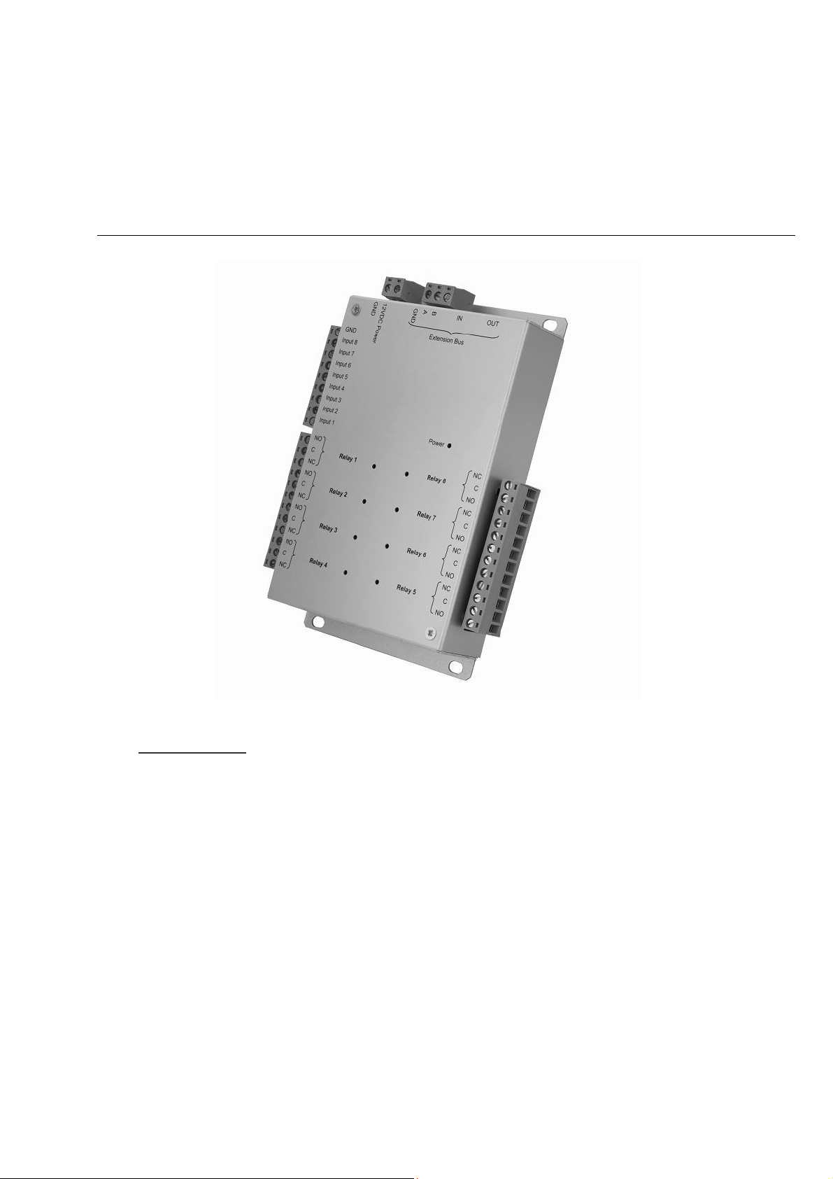
FUNCTIONS OF THE TERMINALS
RS485
Extension Bus
Warning: for all inputs (2- or 4-state), take care to use the module GND as common. For all outputs, take care to use
the diodes supplied with the product if you are controlling electromagnetic devices (bolt, door lock, relay, etc.).
1247066_User’s Manual_Rev1.0_IP-EXTIO Page 6/6
 Loading...