

Page 1
User’s Manual
IP-EXT4
CONTENTS
INFORMATION AND RECOMMENDATIONS ................................................................................................ 2
TECHNICAL CHARACTERISTICS ................................................................................................................ 2
1) IP-EXT4 ........................................ 2
2) PROTECTION .............................. 2
CONNECTING A DEVICE USING THE WIEGAND OR CLOCK & DATA PROTOCOL ................................ 3
CONNECTION TO THE IP-12 UNIT ............................................................................................................... 4
CONNECTING A POWER LOSS BOLT AND AN ELECTROMAGNETIC DOOR LOCK OPERATING
ON POWER LOSS ......................................................................................................................................... 5
CONNECTING A STANDARD POWER-ON DOOR LOCK ........................................................................... 6
SETTING UP THE MODULE IN DOMOS ....................................................................................................... 7
FUNCTIONS OF THE TERMINALS ............................................................................................................... 8
1247065_User’s Manual_Rev1.0_IP-EXT4 Page 1/8
Page 2

INFORMATION AND RECOMMENDATIONS
• This product complies with the requirements of the 1999/5/ CEE R&TTE Directive, 2004/108/EC Directive on
electromagnetic compatibility and 2006/95/EC on low voltage, insofar as the product is used correctly.
• Cabling recommendations: the cables used to connect readers, the network and other peripherals must be
installed in accordance with the instructions for Level 2 (protected environment) of standard NF EN 61000-4-
4.
• This product must be installed by an approved company. Incorrect installation and use may result in elec-
tric shock or fire. Before installation, read the technical information and comply with the recommendations for
assembling the product.
TECHNICAL CHARACTERISTICS
1) IP-EXT4
Maximum power consumption .................... 400 mA
Supply voltage ............................................. 9 – 14VDC
Weight with housing .................................... 200 g
Housing dimensions .................................... 157 x 120 x 30 mm
Operating temperature ................................ - 20°C to + 50°C
Control relay ................................................ 1A / 12V – 1A / 24V
2) PROTECTION
The module is fitted with a 5x20 1A fuse on the 12V input inside the housing. If the power light does not come on
when the module is switched on, check this fuse.
1247065_User’s Manual_Rev1.0_IP-EXT4 Page 2/8
Page 3
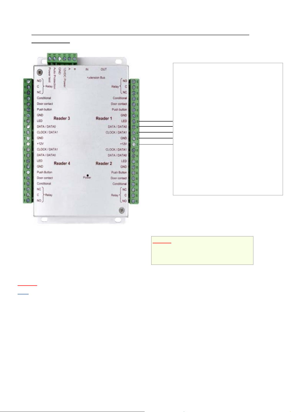
CONNECTING A DEVICE USING THE WIEGAND OR CLOCK & DATA
PROTOCOL
WIEGAND:
o Proximity readers
(HID, STID, DESTEIR, INDALA, etc.)
o Key pads (XPR, etc.)
o Biometric readers (SAGEM, etc.)
o Radio receivers (TECHNO EM, etc.)
o DALLAS (via interface)
CLOCK & DATA:
o Magnetic strip readers
o Barcode readers
o Proximity readers
o Radio receivers
Information:
5 conductors (3 pairs recommended)
Max. distance: 150 m
Cable type: 0.6 mm (SYT recommended)
Shield: Optional
Warning
Note
: Do not install the cables near other high voltage or high current cables, particularly 220V or higher.
: Each reader can have different technology (e.g. Reader 1 using Wiegand, Reader 2 using Clo c k & Data).
Warning: If you use an external power supply
for your proximity readers, take care to connect
the various earths to that of the module.
1247065_User’s Manual_Rev1.0_IP-EXT4 Page 3/8
Page 4

CONNECTION TO THE IP-12 UNIT
Up to 10
modules per
IP-12
A
IP-12 IP-EXT4
A A
B B
RS485
You can also use the A and B terminals on the IP-EXT4 modules to connect an RS485 bus.
Information:
2 conductors (2 pairs recommended)
Max. distance: 750 m
Cable type: 0.6 mm (SYT recommended)
Warning
same pair for the A and B lines.
: Do not install the cables near other high voltage or high current cables, particularly 220V or higher. Use the
1247065_User’s Manual_Rev1.0_IP-EXT4 Page 4/8
Page 5

A
CONNECTING A POWER LOSS BOLT AND AN ELECTROMAGNETIC DOOR
LOCK OPERATING ON POWER LOSS
Power supply
+12V 0V
nti-return diode
Warning: In order to prevent random malfunctions that may interfere with proper system operation due to back-
currents, it is imperative to use and connect the anti-back-current diodes supplied with the unit in compliance with the
cabling diagram above.
Even when using an additional uninterruptible power supply for locking separate to that of the unit, it is obligatory to
follow the above cabling diagram.
1247065_User’s Manual_Rev1.0_IP-EXT4 Page 5/8
Page 6

A
CONNECTING A STANDARD POWER-ON DOOR LOCK
nti-return diode
Power supply
+12V 0V
Warning: In order to prevent random malfunctions that may interfere with proper system operation due to back-
currents, it is imperative to use and connect the anti-back-current diodes supplied with the unit in compliance with the
cabling diagram above.
Even when using an additional uninterruptible power supply for locking separate to that of the unit, it is obligatory to
follow the above cabling diagram.
1247065_User’s Manual_Rev1.0_IP-EXT4 Page 6/8
Page 7

SETTING UP THE MODULE IN DOMOS
To configure your DOMOS software, you will need the module identifier. This is printed on a sticker on the top of the
housing (e.g. ID: 00001). Make a note of this number.
Click on the “Technique” (Technical) button and then “Configuration du site” (Site config uration).
Under the unit your module is connected to, click on “Modules portes” (Door modules) and then “Ajouter un module”
(Add a module).
The following window will then be displayed:
Enter the identifier of your module
Configure degraded mode operation (loss of connection between the
module and the unit)
1247065_User’s Manual_Rev1.0_IP-EXT4 Page 7/8
Page 8

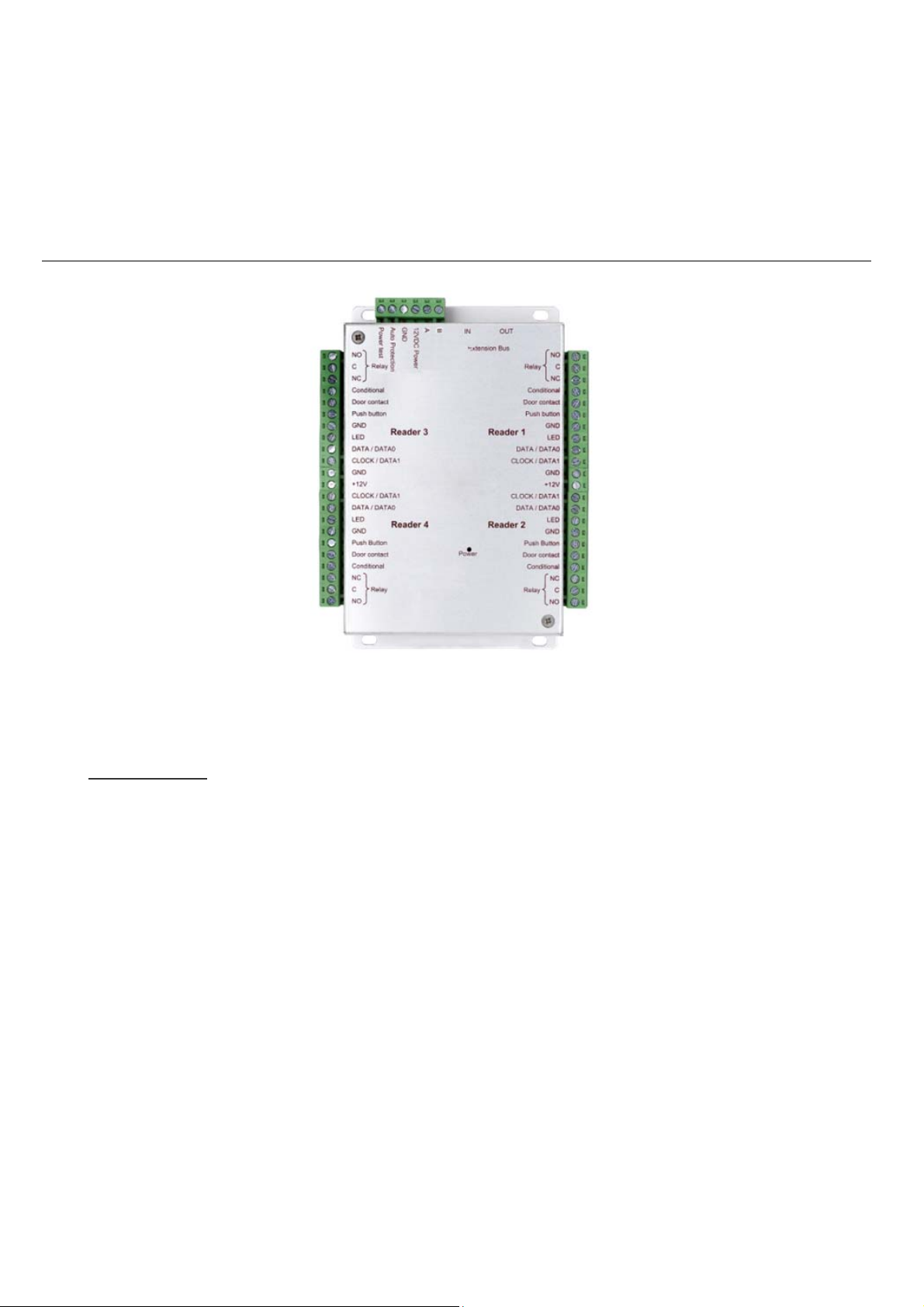
FUNCTIONS OF THE TERMINALS
RS485
Extension Bus
1247065_User’s Manual_Rev1.0_IP-EXT4 Page 8/8
 Loading...