

Page 1
User’s Manual
IP-12
CONTENTS
INFORMATION AND RECOMMENDATIONS .................................................................................... 2
TECHNICAL CHARACTERISTICS ..................................................................................................... 2
1) IP-12 ............................................. 2
2) PROTECTION .............................. 2
CONNECTING A DEVICE USING THE WIEGAND OR CLOCK & DATA PROTOCOL .................... 3
CONNECTING IP-EXT4 MODULE .................................................................................................... 4
CONNECTING A POWER LOSS BOLT AND AN ELECTROMAGNETIC DOOR LOCK
OPERATING ON POWER LOSS ........................................................................................................ 5
CONNECTING A STANDARD POWER-ON DOOR LOCK ................................................................ 6
CONNECTING THE IP-12 UNIT TO AN ETHERNET NETWORK ...................................................... 6
INSTALLATION OF DOMOS DONGLE.............................................................................................. 7
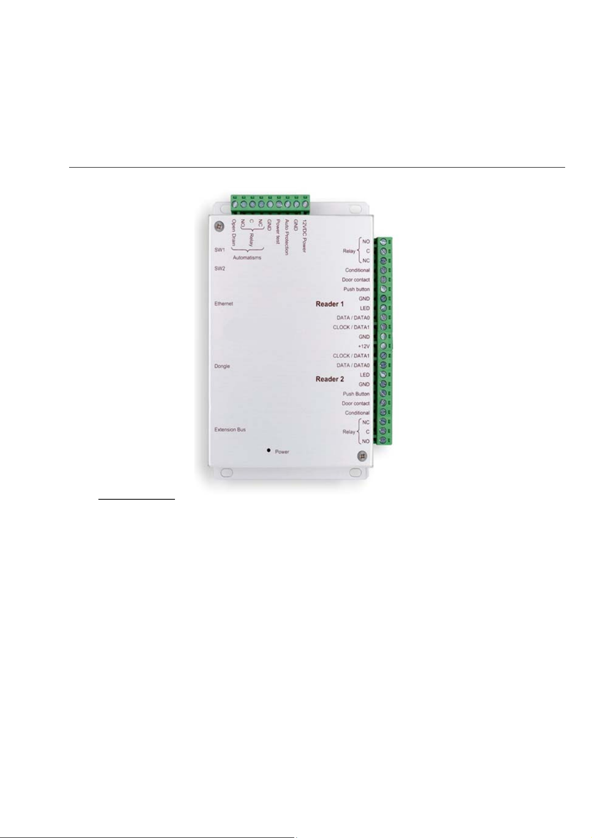
FUNCTIONS OF THE TERMINALS .................................................................................................... 8
USE OF THE RESET BUTTONS ........................................................................................................ 8
1247064_User’a Manual_Rev1.0_IP-12 Page 1/8
Page 2

INFORMATION AND RECOMMENDATIONS
• This product complies with the requirements of the 1999/5/ CEE R&TTE Directive, 2004/108/EC Directive on
electromagnetic compatibility and 2006/95/EC on low voltage, insofar as the product is used correctly.
• Cabling recommendations: the cables used to connect readers, and the network and other peripherals must
be installed in accordance with the instructions for Level 2 (protected environment) of standard NF EN 61 0004-4.
• This product must be installed by an approved company. Incorrect installation and use may result in elec-
tric shock or fire. Before installation, read the technical information and comply with the recommendations for
assembling the product.
TECHNICAL CHARACTERISTICS
1) IP-12
Maximum power consumption .................... 300 mA
Supply voltage ............................................. 9 – 14VDC
Weight with housing .................................... 150 g
Housing dimensions .................................... 157 x 108 x 30 mm
Operating temperature ................................ - 20°C to + 50°C
Control relay ................................................ 1A / 12V – 1A / 24V
2) PROTECTION
The unit is fitted with a 5x20 1A fuse on the 12V input inside the housing. If the power light does not come on when
the unit is switched on, check this fuse.
1247064_User’a Manual_Rev1.0_IP-12 Page 2/8
Page 3
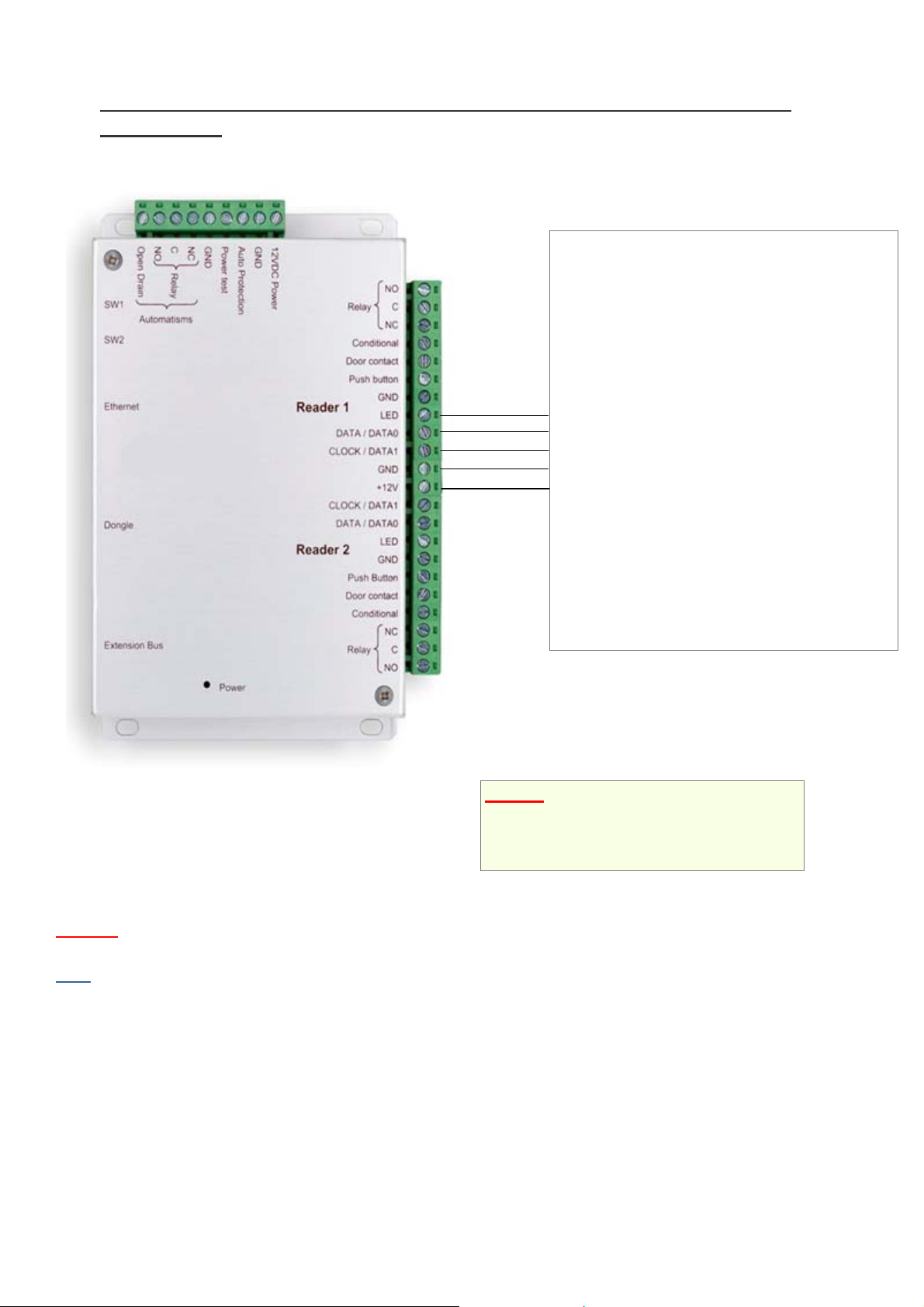
CONNECTING A DEVICE USING THE WIEGAND OR CLOCK & DATA
PROTOCOL
Led
DATA0 / DATA
DATA1 / CLOCK
0V
+12V/200mA max
WIEGAND:
o Proximity readers
(HID, STID, DESTEIR, INDALA, etc.)
o Key pads (XPR, etc.)
o Biometric readers (SAGEM, etc.)
o Radio receivers (TECHNO EM, etc.)
o DALLAS (via interface)
CLOCK & DATA:
o Magnetic strip readers
o Barcode readers
o Proximity readers
o Radio receivers
Information:
5 conductors (3 pairs recommended)
Max. distance: 150 m
Cable type: 0.6 mm (SYT recommended)
Shield: Optional
Warning
higher.
Note
: Do not install the unit-reader cables near other high voltage or high current cables, particularly 220V or
: Each reader can have different technology (e.g. Reader 1 using Wiegand, Reader 2 using Clo c k & Data).
Warning: If you use an external power supply
for your proximity readers, take care to connect
the various earths to that of the unit.
1247064_User’a Manual_Rev1.0_IP-12 Page 3/8
Page 4

CONNECTING IP-EXT4 MODULE
Up to 10
modules per
VERSO
A
VERSO V-EXT4
A A
B B
RS485
You can also use the A and B terminals on the IP-EXT4 modules to connect an RS485 bus.
Information:
2 conductors (2 pairs recommended)
Max. distance: 750 m
Cable type: 0.6 mm (SYT recommended)
Warning
same pair for the A and B lines.
: Do not install the cables near other high voltage or high current cables, particularly 220V or higher. Use the
1247064_User’a Manual_Rev1.0_IP-12 Page 4/8
Page 5

A
CONNECTING A POWER LOSS BOLT AND AN ELECTROMAGNETIC DOOR
LOCK OPERATING ON POWER LOSS
Power supply
+12V 0V
nti-return diode
Warning: In order to prevent random malfunctions that may interfere with proper system operation due to back-
currents, it is imperative to use and connect the anti-back-current diodes supplied with the unit in compliance with the
cabling diagram above.
Even when using an additional uninterruptible power supply for locking separate to that of the unit, it is obligatory to
follow the above cabling diagram.
1247064_User’a Manual_Rev1.0_IP-12 Page 5/8
Page 6

A
CONNECTING A STANDARD POWER-ON DOOR LOCK
nti-return diode
Power supply
+12V 0V
Warning: In order to prevent random malfunctions that may interfere with proper system operation due to back-
currents, it is imperative to use and connect the anti-back-current diodes supplied with the unit in compliance with the
cabling diagram above.
Even when using an additional uninterruptible power supply for locking separate to that of the unit, it is obligatory to
follow the above cabling diagram.
CONNECTING THE IP-12 UNIT TO AN ETHERNET NETWORK
Straight cable Straight cable
Crossed cable
Each IP-12 unit has an IP address. This address is printed on a sticker on the unit housing.
1247064_User’a Manual_Rev1.0_IP-12 Page 6/8
Page 7

To configure a different IP address, you can use the “Automatic detection” menu in DOMOS. To do this, proceed as
follows:
• After having created your installation, on first start up, DOMOS offers to create a new unit
• Click on the “Search” button
• A list of detected units will appear
• Double click on the unit you want to add
• Check the equipment list to confirm that your unit is properly connected.
INSTALLATION OF DOMOS DONGLE
To use the DOMOS software, you must, in certain cases (see following table), install a dongle on your unit.
Use of the dongle
Number of readers in the installation Software Dongle
Up to 10 readers DOMOS Dongle required
Up to 40 readers DOMOS-40 Dongle required
Up to 80 readers DOMOS-80 Dongle required
Up to 140 readers DOMOS-140 Dongle required
Up to 840 readers DOMOS-840 Dongle required
Installation of dongle: with the power off, install the dongle as shown below:
To confirm proper operation, DOMOS shows the version being used at the bottom of the main screen. Your unit must
be rated for the dongle to be detected.
If you do not have the correct dongle for your installation type, your units will be displayed “rated” in the equipment list
but no updates or event collection will be performed.
1247064_User’a Manual_Rev1.0_IP-12 Page 7/8
Page 8

FUNCTIONS OF THE TERMINALS
Reset switch 1
Reset switch 2
Ethernet network
extension bus
RS485
USE OF THE RESET BUTTONS
Use this switch to restore the factory network settings (IP address:
192.168.2.150, mask 255.255.255.0).
Turn off the power.
Hold the switch down while turning the power back on
Wait until the relays engage (about 20 seconds) holding the switch
down
Release the switch
Use this switch to clear the unit memory
Turn off the power.
Hold the switch down while turning the power back on
Wait until the relays engage (about 20 seconds) holding the switch
down
Release the switch
1247064_User’a Manual_Rev1.0_IP-12 Page 8/8
 Loading...