

Page 1
COD. 1257012-GB / 3.0
INTEGRA
GENERAL DESCRIPTION
Control panel for the control of three-phase motors to 3CV at 400V and single-phase motors to 1.5CV at 230V for industrial
doors. It allows dead-man open and close operations, automatic dead-man close operations, semi-automatic operations and
automatic operations. Connection to portable programmer. Anti-intrusion function. It allows dead-man function when a
security fails. LAMP LED will blink indicating security activated.
TECHNICAL CHARACTERISTICS
INTEGRA-ECO (standard box model)
_Panel supply 400V ac 3N / 230V ac
Power 3CV / 1.5CV
Optional cards Receiver card, Radioband/RCS, signal, magnetic detector
24Vac output 24V ac / 0.5A (shared with photocell test output)
Photocell autotest output 24V ac / 0.5A (shared with security device output)
Auxiliary contact outlet Electro-brake / Electro-lock / Garage light
230V ac outlet
Operating temperature -20ºC to +85ºC
Sizes 225x195x85 mm 305x225x126 mm
Airtightness IP54 IP56
Equipment category Class II
Limited to (0.05A, 11W) powered at 400V
Limited to (3A, 600W) powered at 230 Vac
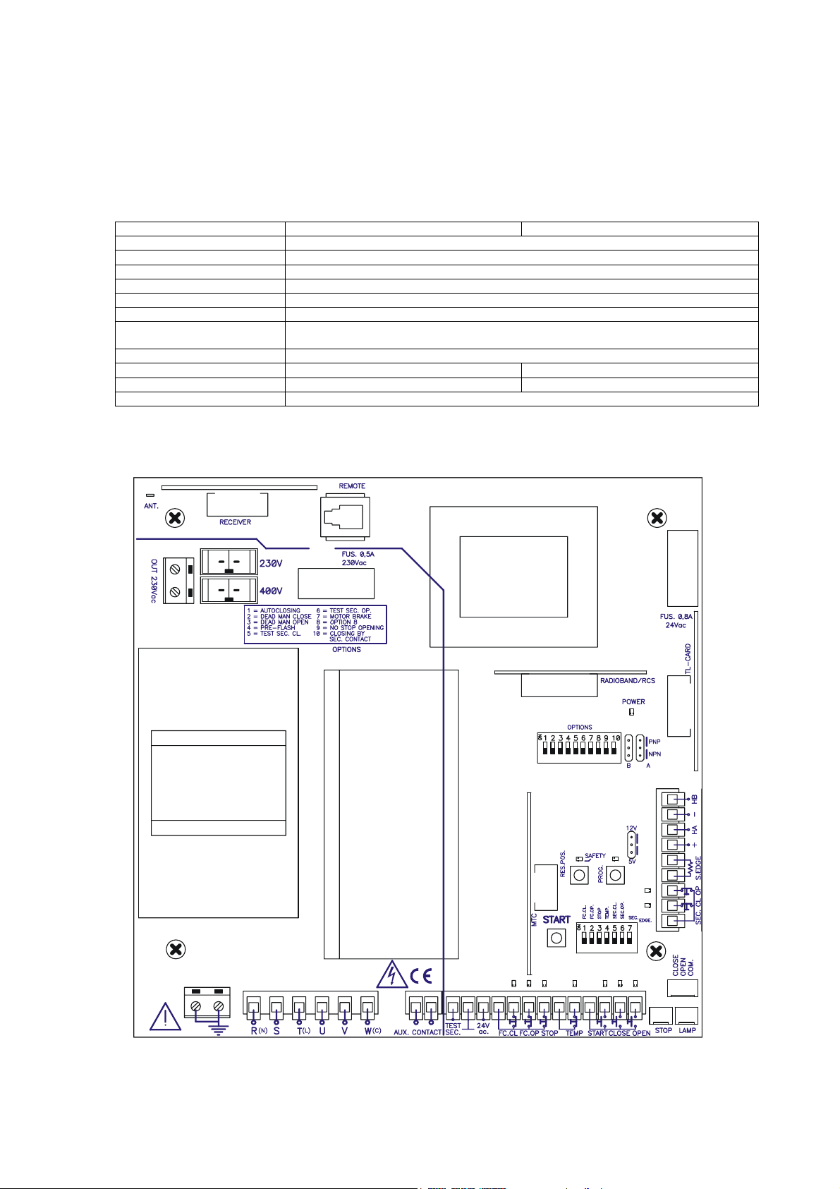
BASE PLATE DESCRIPTION
INTEGRA (Industrial box model)
23 24
14 15 16 17 18 19 20 21 22
25 26 27 28 29 30 31 32 33 34
- 1 -
1 2 3 4 5 6 7 8 9 10 11 12 13
Page 2

COD. 1257012-GB / 3.0
INTEGRA
CONEXIÓN
1 Test for security parts 24Vac
2 Common for security part test and 24Vac outlet
3 24Vac outlet
4 Common ends of run and stop
5 End of run Close (NC)
6 End of run Open (NC)
7 Stop button (NC)
8 Common temperature contact
9 Temperature contact (NC)
10 Common buttons
11 Alternative button (NO)
12 Close button (NO)
13 Start button (NO)
14 Common securities
15 Security Close contact (NC)
16 Security Open contact (NC)
17 Security Close edge (resistive contact 8k2)
18 Security Close edge (resistive contact 8k2)
19 Sensor hall power (+) 12Vdc/+5Vdc depending on switch
20 “Sensor hall” HA signal inlet.
21 Sensor hall power (-) 12Vdc/5Vdc depending on switch
22 “Sensor hall” HB signal inlet
23 230V ac outlet
24 230V ac outlet
25 earthing terminal
26 earthing terminal
27 R(N) power supply connection 230V/400V or neutral
28 S power supply connection 400V
29 T(L) power supply connection 230V/400V
30 U triple phase motor connection/ single phase
31 V triple phase motor connection/ single phase
32 W(C) triple phase motor connection/ common single phase
33 auxiliary contact outlet
34 auxiliary contact outlet
LINE CONNECTION
MOTOR CONNECTION
230V SINGLE-PHASE
N
R
400V THREE-PHASE
R
S
T
R(N)S T(L)
RST
230V
THREE-PHASE
R
S
T
R(N)S T(L)
UVW
THREE-PHASE MOTOR
UVW
SINGLE-PHASE MOTOR
230V
Warning: Where working with 230V connection, turn the switch to 230Vac, and where working with 400V three-phase
connection, turn the switch to 400Vac.
- 2 -
Page 3

COD. 1257012-GB / 3.0
INTEGRA
INSTALLATION
Any handling of the panel for installation must be carried out with the power supply disconnected.
FITTING THE CASING
· Parts: front casing and container box.
· Unscrew the securing points. Insert the cables through the lower holes.
IMPORTANT CONSIDERATIONS FOR START-UP
Check that the Open button opens and the Close button closes. Where this is not the case, invert motor cables U and V.
Any optional cards must be connected to the panel with the power supply disconnected.
OPERATING
Open (OPEN): Contact normally open to open. If pressed during the closing operation it stops and opens (until the end of the
limit switch). Acts as “Dead-Man” if kept pressed down with Option 3 of the options switch triggered.
Close (CLOSE): Contact normally open to close. If it is pressed while the door is opening, it stops. Acts as “Dead-Man” if
kept pressed down with Option 2 of the options switch triggered.
Start (START): Contact normally open to open and close. The first press opens, the second press stops (until the limit switch)
and the third closes. If pressed during the closing operation it stops and inverts (until the end of the limit switch).
The Start contact only acts as an open button when using a traffic light card with traffic control enabled.
Temperature (TEMP): Contact normally closed for connection to a temperature sensor for the motor. When it indicates that
the motor has exceeded the security limit, the operation will stop until it has cooled. Where not used, turn option 4 (TEMP)
on the input switch to ON.
Stop (STOP): Contact normally closed. This detains the operation on standby for a new order. Where not used, turn option 3
(STOP) on the input switch to ON.
Ends of run (FC.CL / FC. OP): contacts normally closed to mechanically indicate the open and closed end of run. Where not
used, turn option 1 (FC.CL) and 2 (FC.OP) on the input switch to ON.
Security contact (SEC.CL / SEC.OP): Contact normally closed, photocell or magnetic detector type. This acts by causing
stoppage and partial inversion during opening and stoppage and total inversion during closure. Where not used, turn option 5
(SEC.CL) and 6 (SEC.OP) on the input switch to ON.
The security close contact also acts as a close button when the vehicle has passed if Option 10 on the options switch is
enabled.
Security edge (SEC.EDGE): Resistive contact for resistive security edge. This acts on closing, causing stoppage and inversion.
Where not used, turn option 7 (SEC.EDGE) on the input switch to ON.
24 Vac output: To power any equipment at a voltage of 24 Vac with a maximum consumption of 0,5A (shared with
photocell test output).
Auto-test output (TEST. SEC): 24 Vac output for auto-test of security parts with a maximum consumption of 0,5A (shared
with 24Vac output).
Auxiliary Contact (Aux. Contact): Normally open contact that has four different functions depending on the position of Option
switches 7 and 8.
Function Option switch 7 Option switch 8
Electro-brake: Enables electro-brake to unblock motor
during operations.
Anti-intrusion function* ON ON
Electro-lock: Enables electro-lock 3 seconds at the start
of the opening operation.
Garage light: Enables garage light during the door
operating time plus 2 minutes.
* Anti-intrusion function:
1. Activates the auxiliary contact on the following cases:
a) if during the opening or closing movements, or with the door opened, it detects the passage of more
than one vehicle by the close safety contact (SEC.CL). If this occurs during the opening movement, the
door will finish opening. If this occurs during the closing, the door will invest up until being completely
open. The door remains opened, without making auto-closing even if it is activated.
b) If the control panel has not given the order to open and closing end of course (FC.CL) is
deactivated. For example, if someone tries to open the door by force.
ON OFF
OFF OFF
OFF ON
- 3 -
Page 4

COD. 1257012-GB / 3.0
INTEGRA
2. Deactivation of the alarm (auxiliary contact):
The alarm will be disabled in any case using the buttons START, OPEN or CLOSE, or by a transmitter
programmed. The STOP button stops the alarm when the door is wide open.
Operation counter: an operation counter and operation limit number is fitted. On reaching the limit number of operations,
the panel switches to dead man operations and the POWER light flashes (only INTEGRA model).
OPTION SWITCH
Option No. Lower position – OFF (default option) Upper position – ON
1 Does not close automatically Automatic closure
2 Operating normally “Dead man” close*
3 Operating normally “Dead man” open*
4 Operating without Pre-signal Pre-signal before handling
5 Operating without C. security close test C. security close test
6 Operating with C. security open test C. security open test
7 Enables option 8 Allows for electro-brake connection in AUX
8 Electro-lock operating if option 7 to OFF Garage light operating if option 7 to OFF
9 Allows for radio reverse on opening Does not allow for radio reverse on
10 The security close contact works are normal The security close contact also acts as the
* The “dead man” close and open moves the door while the button is pressed down.
SELECTOR DE ENTRADAS
Option No. Lower position - OFF Upper position – ON (default option)
1 (FC.CL) End of run close connected End of run close not connected
2 (FC.OP) End of run open connected End of run open not connected
3 (STOP) Stop button connected Stop button not connected
4 (TEMP) Temperature contact connected Temperature contact non connected
5 (SEC.CL) Security Close contact connected Security Close contact not connected
6 (SEC.OP) Security Open contact connected Security Open contact not connected
7 (SEC.EDGE) Security Close edge connected Security Close edge not connected
BUTTONS
START Start/stop button
PROG Programming button
RES POS Position reset button. *
* This button performs the position reset when the panel operates using sensor hall. To do so, the door must be totally
closed and the button kept pressed down until the programming led flashes.
TIMES
Controlling Minimum Maximum
Motor operating 1s 180s
Wait for automatic close 1s 180s
LIGHT INDICATORS
POWER Indicates power
PROG Indicates programming
STOP/SAFETY
LAMP (LED located
at the top, in
INTEGRA model)
INPUT LIGHT INDICATORS
Function
Indicates Default status
OPEN Open function Normally off
CLOSE Close function Normally off
START Open/close function Normally off
TEMP Temperature sensor Normally on
STOP Stop button Normally on
FC.OP End of run Open Normally on
CONTACT
opening
close button when the vehicle has passed
Number of flashes Error Code
1 flash Security edge autotest error 1
2 flashes security close contact autotest 2
3 flashes security open contact autotest 3
4 flashes Security edge error 4
5 flashes RADIOBAND/RCS card autotest error 5
6 flashes Sensor Hall error 6
Blinks indicating security activated
- 4 -
Page 5

COD. 1257012-GB / 3.0
INTEGRA
FC.CL End of run Close Normally on
SEC.OP Security Open contact Normally on
SEC.CL Security Close contact Normally on
PARAMETER CONFIGURATION FROM PROGRAMMER
There are different parameters that can be configured by portable programmer. Below is a description of the most basic.
Refer to the programmer instruction manual for further information.
- Operation by Time: Indicates / selects if the panel is programmed to operate by time.
- Operation by Pulses: Indicates / selects if the panel is programmed to operate by pulses.
- Oper. counter limit: Indicates / selects the limit number of operations for the panel.
- Operation counter: Indicates the number of operations made to date.
- Oper.Count.Limit Active: Indicates / selects if there is a limited number of operations or not.
- Autoclosing time: Indicates / selects the seconds of automatic standby time.
Equip.: Shows an equipment identifier.
-
PROGRAMMING
· During programming, the control panel does not take all possible securities into account.
· Before starting any type of time programming, it is wise to have the corresponding options correctly selected and ensure the
cards to be used are inserted.
· Where RADIOBAND/RCS cards are used, the panel must be programmed with the card inserted.
· Operations can be programmed indifferently using the “Test” / “Start” button or through a transmitter recorded on a
pluggable radio card for control panels.
· Where a sensor hall is used, its pulse type is memorised in the panel during programming.
Programming with ends of run and automatic close
Close the door with the limit switches (where applicable) duly connected.
Press the TIMER PROG button to enter programming. The red PROG led with light up. The first time TEST is pressed, the
door opens to the end of run open and the automatic standby timer begins. The second time TEST is pressed, the automatic
standby timer stops and the door closes to the end of run close.
Press the TIMER PROG button again to exit programming (the red PROG led will switch off).
OPTIONAL CARDS
Receiver card
This acts on the panel with transmitters, proximity keys or smart cards in the same way as the start button.
If working with a receiver card for dead-man* and options 2 and 3 of the options switch are ON, channel 1 opens and
channel 2 closes.
In any other case, channel 2 is not operative.
* (only available in 868MHz)
Traffic light card
This has three different functions (with switch* to OFF)
Output 1: signal.
Output 2: garage light contact – acts for the entire time that the door is operating, plus 10 seconds.
Outlets 3 and 4: traffic lights. Outlet 3 activates the red traffic light that works during door movement. Outlet 4 activates the
green traffic light that is only lit when the door is fully open.
- 5 -
Page 6

COD. 1257012-GB / 3.0
INTEGRA
Traffic control (with switch* to ON)
When this option is activated, the traffic light interprets the Alternative contact as an outdoor open button and the Open
contact as the indoor open button.
While the door remains closed, no signals are given. When the open order is received, the indoor and outdoor red light
contact gives a warning flash for 3 seconds before carrying out the operation.
As the door is opening, the two red lights will switch on (indoor and outdoor).
Once the door is open, the corresponding lights will come on, depending on the activation point:
PUSHBUTTON ACTIVATION RED SIGNAL GREEN SIGNAL
OPEN Interior open button Exterior lamp Interior lamp
START Exterior open button Interior lamp Exterior lamp
Before beginning the close manoeuvre, the interior or exterior green light contact (depending on the case) will give an
intermittent pre-warning of 3 seconds. While the door is closing, the two red lamps will light (interior/exterior).
* Warning: this switch must be enabled and disabled using when the power supply to the panel is disconnected.
Signal card
Through the contact of a relay intermittently activated, this gives a warning 3 seconds before the opening and closing
movements are started. During the movement the relay remains activated fix.
RADIOBAND/RCS card
Optional radio-communications card for security edges.
Magnetic detector card
This allows for the same function as an outside magnetic detector although without the need for an external power supply. It
can be used as an open button and/or security contact. It also includes the frequency changer selection and delay application
for presence deactivation.
IMPORTANT SAFETY INSTRUCTIONS FOR INSTALLATION
· Before installing the panel, remove all unnecessary ropes or chains and disable any equipment such as locks that is not
necessary for the automatic operation.
· Before installing the panel, check that the door is in good mechanical condition, correctly balanced and that it opens and
closes correctly.
· Install the manual unlocking device at a height lower than 1.8m.
· Install any permanent control next to the door away from any moving part and at a minimum height of 1.5m.
· An easily accessible disconnection device must be fitted to the wiring for permanently connected equipment. This device
must ensure the single-pole cut-off of power. It is wise for this to be an emergency switch/isolator.
· Where the panel is supplied without an emergency stop button, this must be incorporated on installation, connected to the
STOP terminal.
· For correct use of the security edge, this must never be activated when the door is fully closed. It is wise to install the ends
of run before activating the edge.
· This equipment can only be handled by a specialist fitter, by maintenance staff or by a suitably trained operator.
· To connect the power supply and motor wiring, 2.5 mm
· Fuses must only be handled when the appliance is disconnected from the mains.
· The instructions for using this equipment must remain in the possession of the user.
· European door normative EN 12453 and EN 12445 specify the following minimum protection and door safety levels:
- for single-family homes, prevent the door being able to come into contact with any object or limit the contact force (e.g.
security edge) and, in the event of automatic closure, a presence detector (e.g. photocell) must be added.
- for communal and public installations, prevent the door being able to come into contact with any object or limit the
contact force (e.g. security edge) and detect presence (e.g. photocell).
2
section terminals must be used.
IMPORTANT SAFETY INSTRUCTIONS FOR USE
· Do not allow children to play with the door controls.
· Keep the remote controls out of the reach of children.
· Watch the door movement and keep people away until the door is fully open or closed.
· Precaution when operating the manual unlocking device, as the door may suddenly fall due to the bad condition of the
springs or door unbalance. Details on how to use the manual unlocking device must be provided by the manufacturer or the
device installer.
· Examine the installation frequently, especially the cables, springs and supports, to detect signs of wear, damage or
unbalance. Do not use the door if repair work or adjustments are required, as this may cause damage.
- 6 -
Page 7

COD. 1257012-GB / 3.0
INTEGRA
EQUIPMENT USE
Designed for the automation of garage doors as per the general description. Not guaranteed for other uses.
The manufacturer reserves the right to modify equipment specifications without prior notice.
JCM TECHNOLOGIES, S.A. declares herewith that the product INTEGRA and INTEGRA-ECO complies with the
requirements of the 2006/42/CE Machines Directive, 2004/108/EC Directive on electromagnetic compatibility and
2006/95/EC on low voltage, insofar as the product is used correctly.
EC DECLARATION OF CONFORMITY
See website: www.jcm-tech.com
- 7 -
 Loading...