

Page 1

A JCM Product
© 2017 JCM Global Corporation
Part No. 960-000194R_Rev. A
NOTE: Due to advancements in industry technologies
and future product development, the information in
this guide is subject to change without notice.
Quick Reference Guide
GEN5™ Printer
For more information about product set up, use, testing procedures
and troubleshooting methods, please contact the T echnical Support
Division of Customer Service via the email addresses listed below:
Americas
support@jcmglobal.com
Europe, Middle East, Africa, Russia & UK
support@jcmglobal.eu
Asia & Oceania
asiasupport@jcmglobal.com
Page 2
GEN5™ Printer
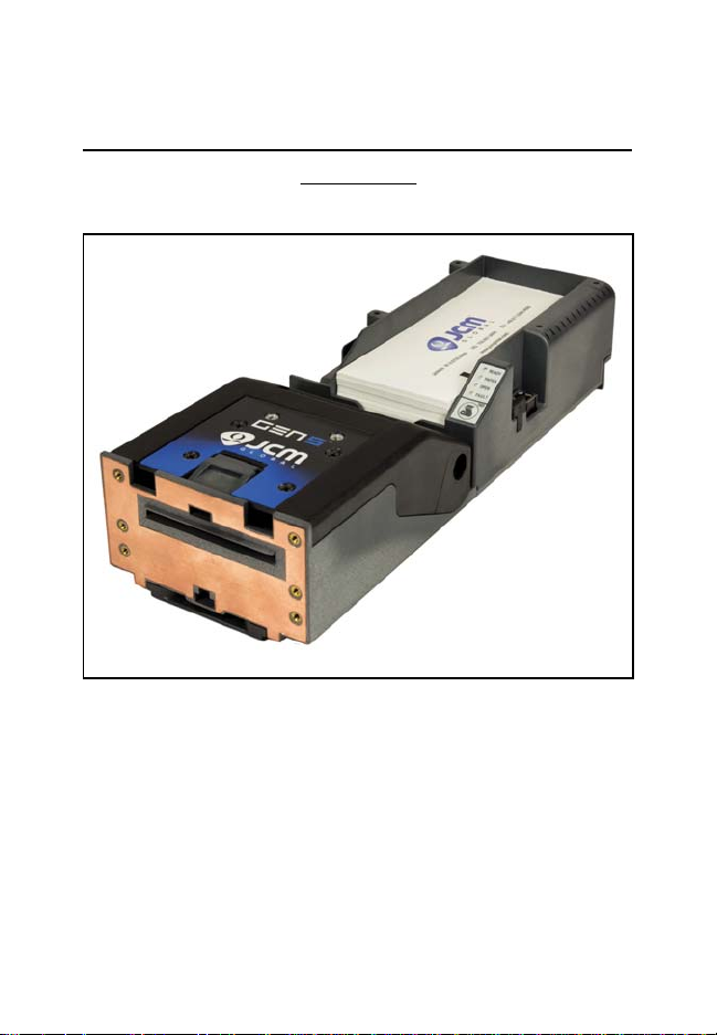
Figure 1 Typical GEN5 Printer
QUICK REFERENCE
TROUBLESHOOTING GUIDE
Introduction
This Quick Reference Guide is designed for use with the GEN5™
line of Printers (Figure 1).
This Guide covers the set-up and use of the following Printer:
PSA-66-ST5.
© 2017 JCM Global Corporation 2 Part No. 960-000194R_Rev. A
Page 3
GEN5™ Printer
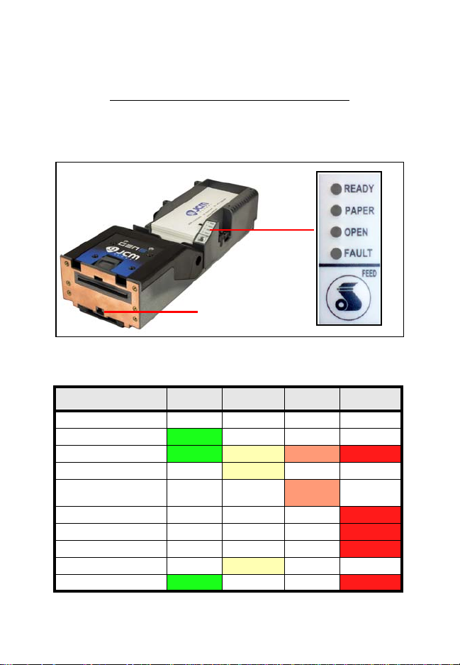
Bezel LED
Connector
Figure 2 GEN5 Printer Keypad, LEDs and FEED Button
Table 1 GEN5 Keypad LED Status Codes
Condition
Ready
Paper Open Fault
Powered OFF
Ready
Blinking
Flushed
Paper Out
Head Up or Ticket
Module Open
Temperature Error
Voltage Error
Print Head Error
Missing Index Marker
Paper Jammed Blinking
Operator Indicators (LED) And Controls
The GEN5 Printer features a Keypad with LED Status Indicators and
a FEED Button (Figure 2). Printer Status indicators include a Front
Bezel Light and the four (4) Keypad LEDs. Refer to Table 1 below
for GEN5 Keypad LED Status Codes.
© 2017 JCM Global Corporation 3 Part No. 960-000194R_Rev. A
Page 4
GEN5™ Printer
NOTE: For current DIP Switch settings, refer to the
Software Information Sheet for the Firmware version
installed in the GEN5 Printer.
B
EZEL OPERATION
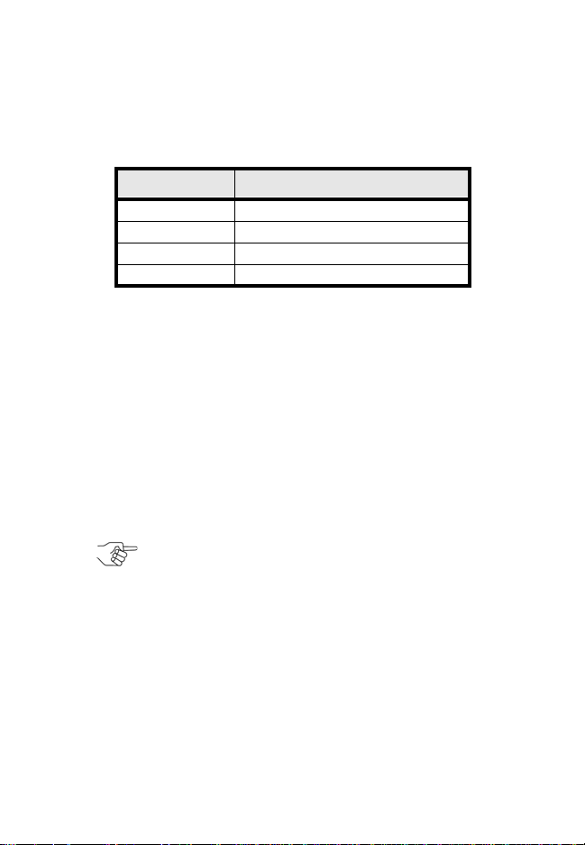
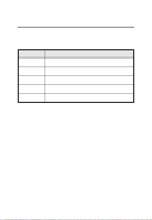
Table 2 identifies the Front Bezel Display indications, which allow
you to determine the Printer Status from a distance.
Table 2 GEN5 Bezel Display Status Indicators
Bezel Display Status
Solid On Printer Idle and Ready
Slow Blink Paper Low or Printer Error
Fast Blink Ticket Printing/Ticket In Chute
OFF Printer Power Off
D
ISABLING/ENABLING THE PAPER LOW SENSOR
To disab le or enable the Paper Low Sensor:
1. Create a Paper Out condition.
2. Create a Paper In Chute condition.
3. Press and hold the FEED button for three (3) seconds.
When the
LED flashes three (3) times. When the
Paper Low Sensor is enabled, the GREEN READY
Paper Low Sensor is
disabled, the RED FAULT LED flashes three (3) times.
GEN5 DIP S
WITCH SETTINGS
The GEN5 Printer has a bank of DIP Switches. The functionality of
the DIP Switch settings is determined by the Firmware loaded into
the GEN5 Printer .
© 2017 JCM Global Corporation 4 Part No. 960-000194R_Rev. A
Page 5
GEN5™ Printer
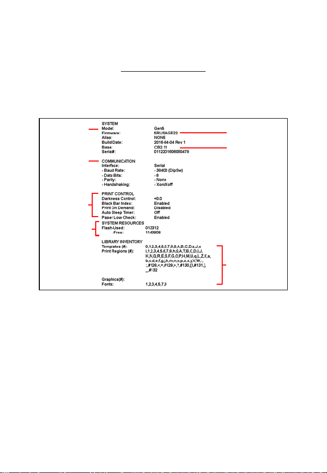
Model Number
System
Communications
Setup
Print Control
Parameters
Amount of
Memory
Resident Ticket
T emplate Packa ge
Version
Firmware Version
Templates, print
regions and fonts
available in the
printer by TCL
page mode
Figure 3 GEN5 Printer Configuration Ticket
Self-Test Procedure
The Self-Test Procedure is used to print a “Configuration T icket” and
verify that the GEN5 Print function operates normally. The Configuration Ticket can be used to check print quality. To print a Configuration Ticket (Figure 3), press the FEED button twice.
© 2017 JCM Global Corporation 5 Part No. 960-000194R_Rev. A
Page 6
GEN5™ Printer
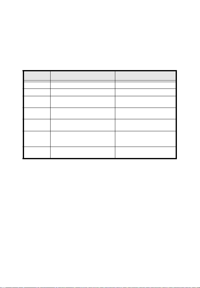
PRINTER SENSOR FUNCTIONS
There are five (5) primary Sensor functions on the GEN5 Printer.
Bezel light and Keypad LEDs may indicate a Sensor-related error
condition (refer to Table 3).
Table 3 GEN5 Printer Sensor Status
Sensor Location/Description
Paper Out
Paper Low
Paper Taken
Drawer Open
Printer Lid Open
Located in the Print Head, Paper Out indicates that paper is
not loaded in the GEN5 Printer.
Located in the Paper Tray, Paper Low indicates that less
than two (2) Tickets are detect ed in the GEN5 Printer.
Located in the Presenter Chute, Paper Taken indicates that a
Ticket remains in the Presenter Chute.
Located on the CPU Board, Drawer Open indicates that the
Printer is not seated properly in the Host Machine.
Located in the Print Head, Printer Open in d ica te s th a t the
Printer Lid is open.
© 2017 JCM Global Corporation 6 Part No. 960-000194R_Rev. A
Page 7
GEN5™ Printer
P
RINTER ERRORS
Most Printer Errors occur due to paper running out or user intervention. See Table 4 below for Error Descriptions and recommended
solutions. Refer to Figure 2 and T able 1 (Page 3) for Error Indicators.
Table 4 GEN5 Printer Errors
Error Description Remedy
Paper Out Paper is not detected. Load new paper stack.
Lid Open The Printer Lid is open. Close the Printer Lid.
Temperature
Voltage
Print Head
Missing
Black Index
Paper Jam
Operating Temperature exceeds
limits.
Power Supply voltage exceeds
acceptable range.
Error due to connectivity or
interface issue with Print Head.
The Black Index Mark is not
detected.
Error in Paper path as Ticket is
presented.
Determine cause of high
temperature, let unit cool down.
Check cabling, apply correct
power level.
Power cycle and reset printer. If
error recurs, service the printer.
Ensure paper meets
specifications and is loaded
correctly.
Open Printer Head, inspect for
jammed Ticket.
© 2017 JCM Global Corporation 7 Part No. 960-000194R_Rev. A
Page 8

GEN5™ Printer
Figure 4 JCM Device Firmware Upgrade
Downloader UI Window/Closeup
NOTE: A USB Hub is recommended. Connect the
USB Hub between the PC and the GEN5 Printer.
UPDATING FIRMWARE ON THE PRINTER
To update Firmware on the GEN5 Printer using a PC:
1. From your PC Desktop, launch the JCM Device Firmware
Upgrade Downloader (JCM DFU) (Figure 4).
2. Make sure the GEN5 Printer is powered ON.
3. Connect a USB cable from the PC to the Printer’s USB port
(right side).
© 2017 JCM Global Corporation 8 Part No. 960-000194R_Rev. A
Page 9

GEN5™ Printer
a
Figure 5 “Printer Detected” Indicator
a
Figure 6 Click Select Firmware
4. To verify communication between the GEN5 Printer and the
Device Firmware Upgrade Application, look for the Printer
Detected indicator (Figure 5
a) in the window.
5. Click the
Select FIRMWARE button to select the desired
Firmware Upgrade file to be downloaded (Figure 6 a).
© 2017 JCM Global Corporation 9 Part No. 960-000194R_Rev. A
Page 10

GEN5™ Printer
a
b
Figure 7 Select the Firmware File to Download
6. From the Firmware Upgrade window (Figure 7), click on the
desired Firmware update file (Figure 7 a) to be downloaded
to the Printer . Then click the
Open button (Figure 7 b) to con-
tinue.
© 2017 JCM Global Corporation 10 Part No. 960-000194R_Rev. A
Page 11

GEN5™ Printer
NOTE: When the ***Printer Successfully Updated***
text line appears, the update is complete.
a
Figure 8 Select the Full Upgrade Button
NOTE: Multiple versions of Firmware can be stored in
the GEN5 System folder.
7. Make sure the Erase User Settings check box is selected.
Then click the Full Upgrade button (Figure 8 a).
8. Press the FEED button twice to print a Configuration Ticket.
9. Verify that the Firmware version printed on the Configuration Ticket matches th e ve rsion downloaded to the Printer.
U
PDATING
GEN5 F
IRMWARE WITH THE BLUEWAVE
™
DX T
To update firmware on the GEN5 Printer using the BlueWaveDX
Tool, perform the following steps:
1. Create a folder in the root directory of the SD Card, named:
GEN5 System.
2. Place the Firmware file for the GEN5 Printer into this new
folder.
OOL
3. Apply power to the GEN5 Printer.
4. Connect a Standard USB Cable between the BlueWaveDX
Tool and the GEN5 Printer USB Download Port.
5. Apply Power to the BlueWa veDX Tool.
© 2017 JCM Global Corporation 11 Part No. 960-000194R_Rev. A
Page 12

GEN5™ Printer
NOTE: When the Firmware has been downloaded,
the GEN5 Printer will reset automatically.
NOTE: The Firmware in the BlueWaveDX Tool must
be Version 2.00 or higher to support the GEN5 Printer
downloading.
6. Select FIRMWARE UPDATE by pressing the OK button on the
BlueW aveDX Tool.
7. Select the Firmware Version by scrolling through the list
using the BlueW av eDX T ool’s UP and DOWN Arrow keys.
8. Press the
OK button to select the required Firmware Version.
9. When
Download Complete appears on the BlueWaveDX Tool
LCD display, press the
CLR button to return to the Main
Menu OR press the OK button to download the selected
Firmware version to another Printer.
A
BOUT THE BLUEWAVE
™
DX PRINTER CONFIG O
PTION
Using the BlueWa veDX Tool, the Bar Code format printed by the
GEN5 Printer can be changed. To do so:
1. Connect the BlueWaveDX Tool to the GEN5 Printer with a
USB Cable.
2. Using the
CONFIG
UP and DOWN Arrow keys, scroll to the PRINTER
option. Press the OK button.
3. Using the UP and DOWN Arrow keys, select the required Bar
Code format from the following options:
a). 4/8 (default)
b). 3/9
c). 4/12
4. Press the OK button to select the Bar Code format.
5. Press the CLR button to return to the Main Menu.
© 2017 JCM Global Corporation 12 Part No. 960-000194R_Rev. A
Page 13

GEN5™ Printer
NOTE: Printers supporting USB Communications also
have RS-232 Active.Test connectivity using an
RS-232 connection.
Figure 9 JCM Printer Basic Driver Opening Screen
ABOUT THE JCM PRINTER BASIC DRIVER
The JCM® Printer Basic Driver allows full testing of a connected
Printer.
C
ONNECTING TO THE
JCM P
RINTER BASIC DRIVER
To connect to the JCM Printer Basic Driver:
1. Click the Start Button on the PC Desktop, then click on Programs.
2. Scroll down to
The
JCM PRINTER BASIC DRIVER Opening Screen appears (Figure 9).
JCM, then click the JCM Printer Basic Driver icon.
3. Select the PROTOCOL (RS-232 or Netplex) and PORT NUMBER.
© 2017 JCM Global Corporation 13 Part No. 960-000194R_Rev. A
Page 14

GEN5™ Printer
a
c
b
d
Figure 10 JCM Printer Basic Driver Main Screen
NOTE: Descriptions of these features appear on
Page 15.
JCM P
RINTER BASIC DRIVER MAIN SCREEN
The JCM Printer Basic Driver Main Screen (Figu re 10) displays three
main sections:
1. PRINTER CONFIGURATION (Figure 10 a)
2. COMMANDS
3. PRINTER STATUS
(Figure 10 b)
(Figure 10 c)
© 2017 JCM Global Corporation 14 Part No. 960-000194R_Rev. A
Page 15

GEN5™ Printer
NOTE: Any active condition appears highlighted in
RED (Figure 10
d).
PRINTER CONFIGURATION (Figure 10 a)
This section displays the current Printer Configuration, including
Version, Firmware Installed and Communication Setup parameters
COMMANDS (Figure 10 b)
This section provides the following functional checks:
• Reset - Performs a reset of the Printer
• Clear - Clears Warning and Error Status
• Flush - Deletes the Firmware on the Printer
• Feed - Feeds one blank Ticket
• Print Ticket Information - Prints a Test Ticket with Printer
Information, Printer Communication Settings, Character Set
and a Test Barcode
• Get Value - Retrieves the Printer CRC information
• Select File - Use Select File to select a properly-formatted ticket
• Send File - Use Send File to print the sample ticket on the Printer
PRINTER STATUS (Figure 10 c)
This section displays the current status of the Printer.
© 2017 JCM Global Corporation 15 Part No. 960-000194R_Rev. A
Page 16

GEN5™ Printer
NOTE: The Cleaning Cycle may need to be changed,
depending on operating environment conditions.
Smoke-filled and/or dusty environments require more
frequent Cleaning Cycles.
PREVENTIVE MAINTENANCE
To ensure high performance printing quality, the GEN5 Printer must
be cleaned periodically using the following methods:
– Perform the Cleaning Card Method every three (3) months.
– Manual Cleaning should be performed every six (6) months.
Cleaning Supplies
Table 5 Required Supplies
Description Part No.
Cleaning Kit, Bagged
Isopropyl Alcohol (I.P.A.) 99% or greater N/A
Non-Flammable Compressed Air N/A
* Cleaning Kit includes (10) Cleaning Swabs (P/N 350-00291-100), (10) Cleaning Wipes
(P/N 350-00259-100) and (10) Cleaning Cards (P/N 350-00287-100).
C
LEANING THE PRINTER
(C
LEANING CARD METHOD
P/N 350-00292-100
)
To clean the Printer using the Cleaning Card Method:
1. Slide the Printer out of the EGM.
2. Remove Tickets from the Printer’s Paper T r ay (see Figure 11 a on page
17).
3. Verify that the Printer is powered ON.
4. Remove the Cleaning Card from its package.
5. Insert the Cleaning Card into the Ticket-In Slot (see Figure 11 d on page
17). The Cleaning Card will feed into the Slot up to the loading point.
6. Press the FEED button to feed the Cleaning Card through the Paper Path.
7. Remove the Cleaning Card from the Printer.
8. Turn the Cleaning Card over.
9. Repeat Steps 5 through 7 for a second cleaning cycle.
10. Reload the Tickets.
11. Feed at least two (2) Tickets through the Printer to wipe off excess
moisture on the Print Head.
*
© 2017 JCM Global Corporation 16 Part No. 960-000194R_Rev. A
Page 17

GEN5™ Printer
d
a
b
c
Figure 11 Cleaning the Ticket-In Slot
NOTE: Insert the Compressed Air canister’s tube into
the Ticket-In Slot approximately 1 inch from the right
edge of the Slot.
Manual Cleaning
Use the following procedure for Manual Cleaning of the Printer:
1. Slide the Printer out of the EGM.
2. Remove Tickets from the Printer’s Paper Tray (Figure 11 a).
3. Press the Lid Release Lever toward the rear of the Printer to release the lid
(Figure 11 b).
4. Rotate the Lid up in the direction indicated by the red arrow (Figure 11 c
and Figure 12 a on page 18) to access the Printer interior.
5. Use Non-Flammable Compressed Air to blow out excessive dust and dirt
from the following areas within the Printer:
– Ticket-In Slot (Figure 11 d)
– Presenter Assembly (refer to Figure 12 b on page 18)
– Print Head (refer to Figure 13 b on page 18)
– Paper Tray (Figure 11 a)
© 2017 JCM Global Corporation 17 Part No. 960-000194R_Rev. A
Page 18

GEN5™ Printer
a
b
Figure 12 Presenter Assembly
a
b
Figure 13 Print Head Release Lever/Print Head
Clean Print Head (b)
with Cleaning Swab
6. Open the Print Head Release Lever (Figure 13 a).
7. Clean the Print Head (Figure 13 b) using a Cleaning Swab.
© 2017 JCM Global Corporation 18 Part No. 960-000194R_Rev. A
Page 19

GEN5™ Printer
a
d
e
Cleaning Paper
Low Sensor (b) with
Cleaning Swab
b
c
b
Figure 14 Sensor Locations
a Printer Tray (Drawer Open) Sensor
b Ticket Low (Paper Low) Sensor
c Paper Out (Index Mark) Sensor
d Lid Open Sensor
e Ticket Taken (Paper Taken) Sensor
8. Clean each of the Sensors using a clean Cleaning Swab (Figure 14).
© 2017 JCM Global Corporation 19 Part No. 960-000194R_Rev. A
Page 20

GEN5™ Printer
a
b
Figure 15 Platen Roller/Feed Roller
9. Use a Cleaning Wipe to wipe and clean the Platen Roller (Figure 15 a).
Rotate the Roller to clean the Roller’s entire circumference.
10. Close the Print Head Release Lever (refer to Figure 13 a on page 18).
11. Use a Cleaning Wipe to wipe and clean the Feed Roller
(Figure 15 b).
12. Use a clean, dry Micro-fiber cloth to wipe excess liquid from all surfaces.
13. Reload the Tickets.
14. Slide the Printer into the EGM.
© 2017 JCM Global Corporation 20 Part No. 960-000194R_Rev. A
Page 21

GEN5™ Printer
Quick Reference Guide
GEN5™ Printer
JCM International
Offices
Europe, Middle East, Africa & Russia
JCM Europe GmbH
Mündelheimer Weg 60,
D-40472 Düsseldorf Germany
Phone: +49-211-530-645-60
Fax: +49-211-530-645-85
E-mail: support@jcmglobal.eu
UK & Ireland
JCM Europe (UK Office)
Unit B, Third Avenue
Denbigh West Business Park
Bletchley, Milton Keynes
Buckinghamshire MK1 1DH UK
Phone: +44 (0) 190-837-7331
Fax: +44 (0) 190-837-7834
E-mail: info@jcmglobal.eu
© 2017 JCM Global Corporation Part No. 960-000194R_Rev. A
Page 22

GEN5™ Printer
Quick Reference Guide
GEN5™ Printer
JCM International
Offices
Americas
JCM American
925 Pilot Road, Las Vegas, NV 89119
Phone: (702) 651-0000
Fax: (702) 644-5512
E-mail: support@jcmglobal.com
Asia and Oceania
JCM Gold (HK) Ltd.
Unit 1-7, 3/F., Favor Industrial Centre
2-6 Kin Hong Street, Kwai Chung
E-mail: asiasupport@jcmglobal.com
JAPAN CASH MACHINE CO., LTD. (HQ)
N.T. Hong Kong
Phone: +852-2429-7187
Fax: +852-2929-7003
2-3-15, Nishiwaki, Hirano-ku
Osaka 547-0035 JAPAN
Office: +81-6-6703-8400
Fax: +81-6-6707-0348
E-mail: Shohin@jcm-hq.co.jp
© 2017 JCM Global Corporation Part No. 960-000194R_Rev. A
 Loading...