

Page 1

GAMMA VERSUS
MANUAL
COD. 1257066 Gamma VERSUS Manual v1.7
The contents of this manual is property of JCM TECHNOLOGIES S.A.
Page 2

GAMMA VERSUS MANUAL
1. 1.INTRODUCTION....................................................................................................................................4
2. INSTALLATIONSTYPES..............................................................................................................................5
2.1 Swing‐door.......................................................................................................................................5
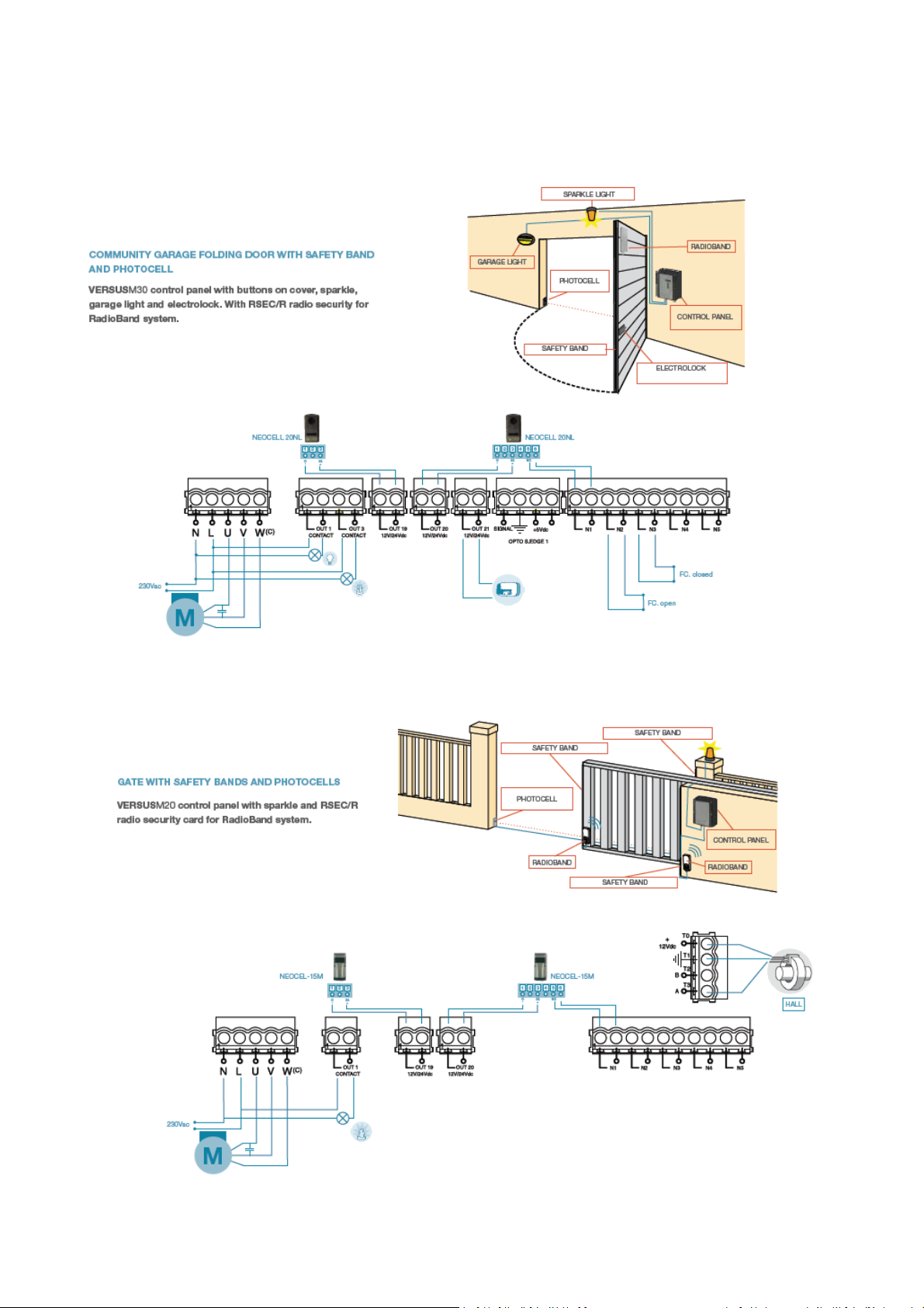
2.2 Gate.................................................................................................................................................5
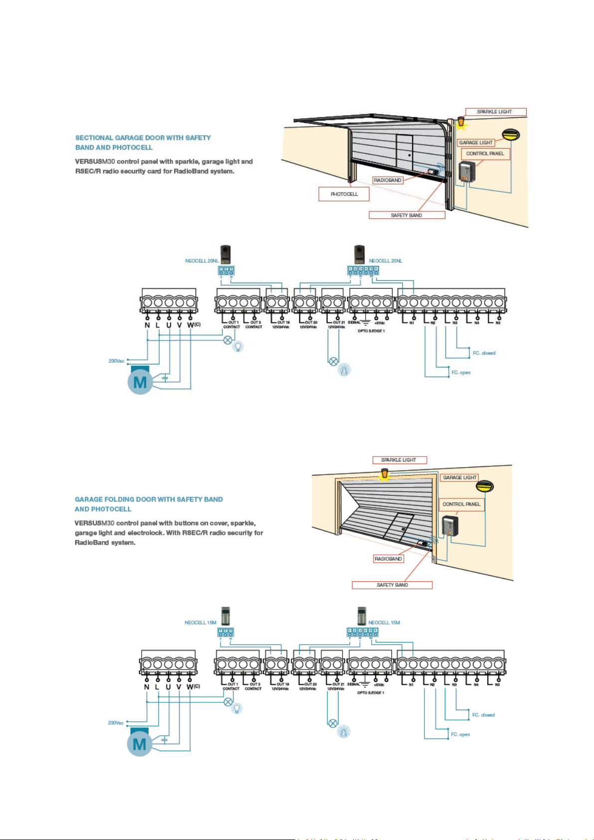
2.3 Sectionaldoor..................................................................................................................................6
2.4 Folding‐door....................................................................................................................................6
2.5 Rolling‐door.....................................................................................................................................7
2.6 Fast‐door..........................................................................................................................................7
3. ASSEMBLYANDINSTALLATION................................................................................................................8
3.1 Installationwithsupport.................................................................................................................8
3.2 Installationwithoutsupport............................................................................................................8
3.3 Reverseinstallation.........................................................................................................................9
4. PARAMETERS..........................................................................................................................................10
4.1 ON/OFFOptionparameters..........................................................................................................10
4.2 Numericparameters......................................................................................................................13
4.3 Switchparameters.........................................................................................................................16
4.4 Inputparameters...........................................................................................................................17
4.5 Outputparameters........................................................................................................................19
4.6 Statusparameters
5. LIGHTINDICATORS.................................................................................................................................21
6. DISPLAYMESSAGES................................................................................................................................21
6.1 Seriouserrors.................................................................................................................................21
6.2 Minorerrors...................................................................................................................................22
6.3 Warnings........................................................................................................................................23
7. VERSUSFUNCTIONS...............................................................................................................................24
7.1 Autoprogrammingfunction...........................................................................................................24
7.2 Hallortimemodefunction............................................................................................................25
7.3 Pedestrianfunction.......................................................................................................................
7.4 SpeedregulationandslowspeedmodeinACmotorsfunction...................................................27
7.5 ACmotorinternallimitswitchesandblockingdetectionfunction...............................................29
7.6 Autoclosingfunction......................................................................................................................31
7.7 Closebysecuritycontactfunction.................................................................................................32
7.8 Deadmanfunction.........................................................................................................................33
7.9 Nostoponopeningfunction.........................................................................................................
7.10 Radiobandfunction.......................................................................................................................35
7.11 Radiosensfunction........................................................................................................................37
7.12 Electrolockandreversestrikeatopenfunctions.........................................................................40
7.13 Backjumpfunction.........................................................................................................................42
7.14 Securitycontactautotestfunction................................................................................................43
7.15 Securityedgeautotestfunction....................................................................................................45
7.16 ClosingsecuritywirededgeorRadiobandinhibitionfunction.....................................................
7.17 Closingsecuritycontactinhibitionfunction..................................................................................48
7.18 Automatic8K2/opticalsecurityedgedetectionfunction.............................................................49
7.19 Flashandpre‐flashfunction..........................................................................................................51
7.20 Anti‐intrusivefunction...................................................................................................................52
7.21 Alarmfunction...............................................................................................................................53
7.22 Panicfunction................................................................................................................................54
7.23 Hydraulicmodefunction...............................................................................................................55
7.24 Recharge
7.25 Passwordblockingfunction...........................................................................................................58
7.26 Trafficcontrolfunction..................................................................................................................59
7.27 Errorandwarningdisplayfunction...............................................................................................60
7.28 Openingfunctionwithpresencedetection...................................................................................61
maneuverfunction........................................................................................................57
.........................................................................................................................20
26
34
47
2
COD. 1257066 Gamma VERSUS Manual v1.7
Page 3

GAMMA VERSUS MANUAL
7.29 Bollardcontrolmodefunction......................................................................................................62
7.30 Maintenancewarningfunction.....................................................................................................64
8. PROGRAMMINGOFMANEUVERS..........................................................................................................65
8.1 Doorpositioning............................................................................................................................65
8.2 DoorpositioninginDeadmanmode.............................................................................................65
8.3 Auto‐Programming........................................................................................................................66
8.4 Auto‐Programmingwithinternallimitswitchesdetection...........................................................67
8.5 ManualProgramming....................................................................................................................68
8.6 ManualProgrammingwithinternallimitswitchesdetection.......................................................69
8.7 ManualProgrammingwithslowspeedfunctionactivated...........................................................70
8.8 PedestrianProgramming...............................................................................................................72
9. PROGRAMMINGCODESINTHERECEIVER.............................................................................................73
9.1 ManualProgrammingMOTIONtransmitters................................................................................73
9.2 Programmingbyradio...................................................................................................................74
9.3 Reset..............................................................................................................................................74
10. ACCESSORIES..........................................................................................................................................75
10.1 VERSUS‐PROGportableprogrammer............................................................................................75
10.2 V‐POTcard.....................................................................................................................................78
10.3 V‐DPLAYcard.................................................................................................................................79
10.4 V‐EXPANDcard..............................................................................................................................82
10.5 Updator..........................................................................................................................................83
11. SAFETYINSTRUCTIONSFORINSTALLATION...........................................................................................86
12. SAFETYINSTRUCTIONSFOR
13. SAFETYINSTRUCTIONSFORMAINTENANCE..........................................................................................88
ANNEXA:SYMBOLOGY...................................................................................................................................89
THEUSE.....................................................................................................87
1.
3
COD. 1257066 Gamma VERSUS Manual v1.7
Page 4

GAMMA VERSUS MANUAL
1. INTRODUCTION
JCM presents a new generation of control panels with adaptable technology to your needs.
With this new range, you set up the control panel, both software and hardware, in order to not to have more
functions than required, and satisfying the concept of "value for money" while applying all the technology
and imagination.
In accordance to the European standard
A new range of control panels designed and prepared to fulfil the requirements of the EN 13241-1 standard
applied to, industrial, commercial, garage... doors, and specially emphasizing the monitoring of a safe
manoeuvre which is the object of the EN 12453 standard.
Design
New range of control panels created to meet the needs of every installation. The range has been designed
following the modularity concept, allowing to customize the board from the very packaging to the software,
as well as the options such as courtesy light, external push buttons, switch power, emergency stop button,
wall mounted support, screws, hinges, the languages of the instruction manual... and others performances
as the customization of the inputs and outputs.
Versatile control units
Under the concept Do It Yourself, the control unit can be customized as the real needs of the client. All the
options and functions of the board can be configurated and modified from JCM (Software previously
agreed), and be modified via radio, by proximity o through cable, directly on the board at the client offices
or in the installation.
Moreover, the design of the box allows installing it up / down and keeping the display always in the correct
position.
Optimum reliability
The new range of JCM control units covers the necessity about flexibility and cost optimization that more
and more is demanded by our customers, without putting aside the quality and innovation that
characterizes JCM.
Time saving and more precision
New pluggable cards designed to make configurations (potentiometers, display, LCD) in addition to the
digital programming used until now. The display card shows in every moment the status of the board and it
is visible from the outside of the control unit. Also, new functions as parameters locking with password,
maintenance warning and detection of the stop of the motor for mechanical top, are incorporated.
The new VERSUSProg, programming tool, allows the board parameters adjustment without the necessity
of cable connection. Also the configuration of the control unit can be done without removing it from its
packaging.
4
COD. 1257066 Gamma VERSUS Manual v1.7
Page 5
GAMMA VERSUS MANUAL
2. INSTALLATIONS TYPES
2.1 Swing-door
2.2 Gate
5
COD. 1257066 Gamma VERSUS Manual v1.7
Page 6
GAMMA VERSUS MANUAL
2.3 Sectional door
2.4 Folding-door
6
COD. 1257066 Gamma VERSUS Manual v1.7
Page 7
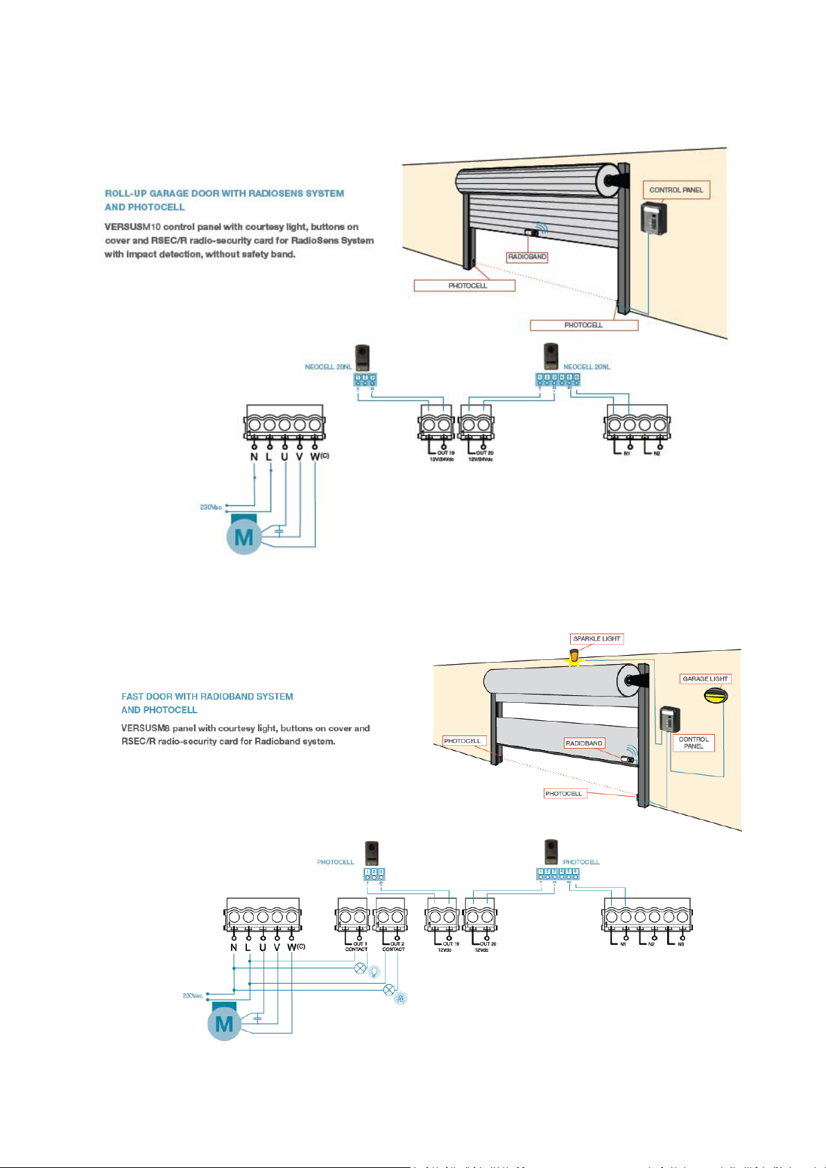
2.5 Rolling-door
GAMMA VERSUS MANUAL
2.6 Fast-door
7
COD. 1257066 Gamma VERSUS Manual v1.7
Page 8
GAMMA VERSUS MANUAL
3. ASSEMBLY AND INSTALLATION
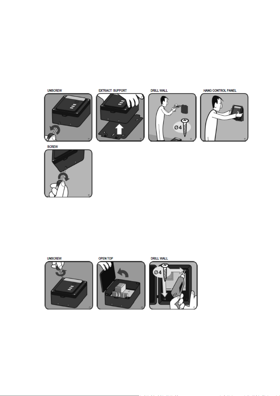
3.1 Installation with support
Unscrew the lower side screws. Separate the control unit from the support. Use support to make the holes
in the wall, and screw the support with 4cm diameter wall screws. Hang the box on the support and screw
the lower side.
3.2 Installation without support
Unscrew the 4 screws from the control unit to be released from the support. Open the door to the left.
Present the box on the wall and mark the two holes with a pencil. Remove the box and make holes in the
wall. Screw the box to the wall with screws, at least 4 cm in diameter.
8
COD. 1257066 Gamma VERSUS Manual v1.7
Page 9
GAMMA VERSUS MANUAL
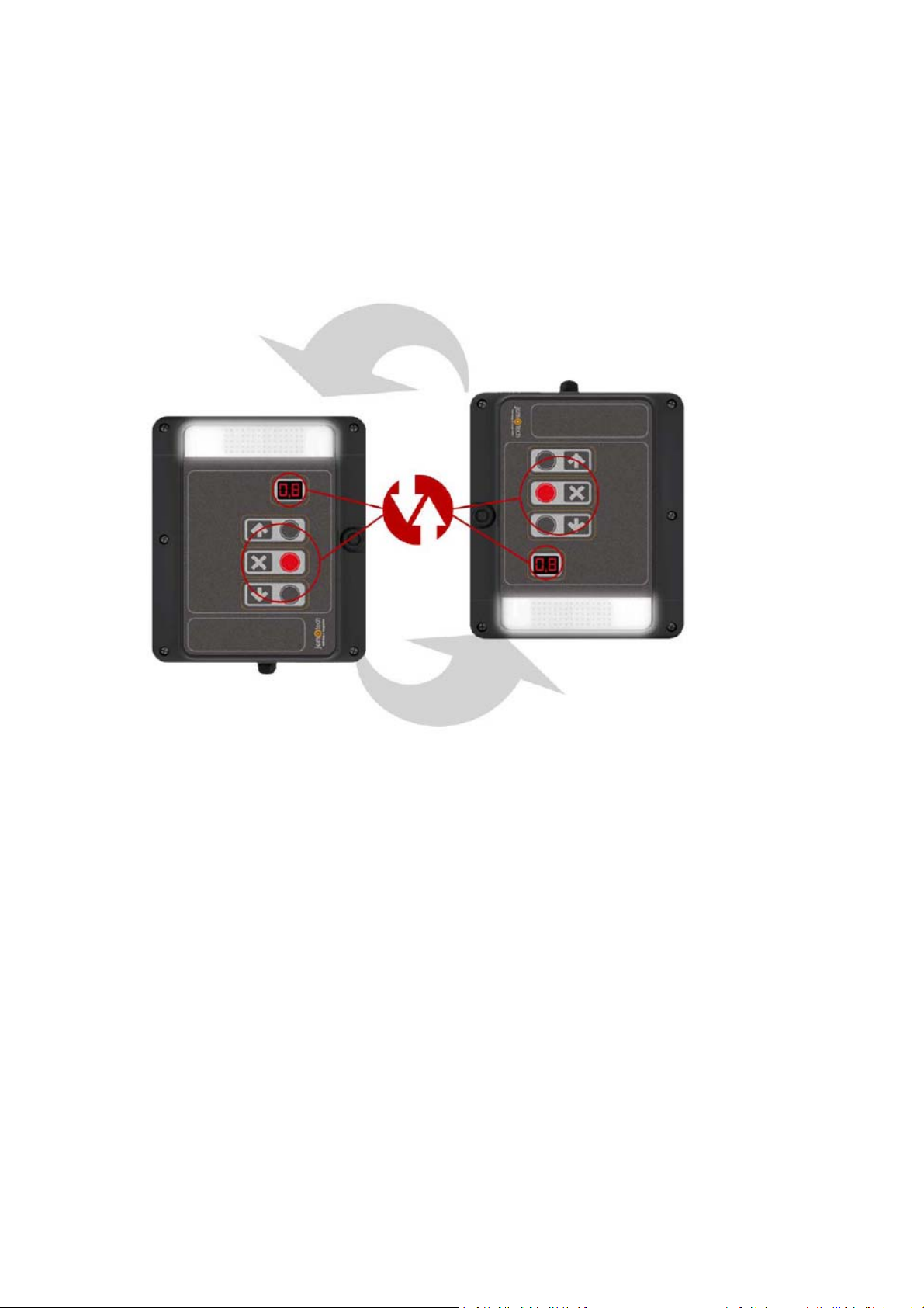
3.3 Reverse installation
The box of the control panel can be mounted upside down. This way the door can be opened to the right.
To do this you only need to screw the box upside down, or mount the support upside down if included.
For the front keypad functions to be rotated, so that the arrows indicating up opens and the arrow indicating
down closes, turn upside down the card VERSUS-DPLAY and VERSUS-POT plugged into the
motherboard.
If you do not have any of them, the front keypad acts the opposite of what logically expected.
9
COD. 1257066 Gamma VERSUS Manual v1.7
Page 10
GAMMA VERSUS MANUAL
4. PARAMETERS
The configurable parameters of the control panels are grouped by parameter type as follows.
All these parameters depend on the installation type, used motor and used safety devices. Furthermore they
depend on the needs of each installation like maneuver timings, speeds of the door, etc…
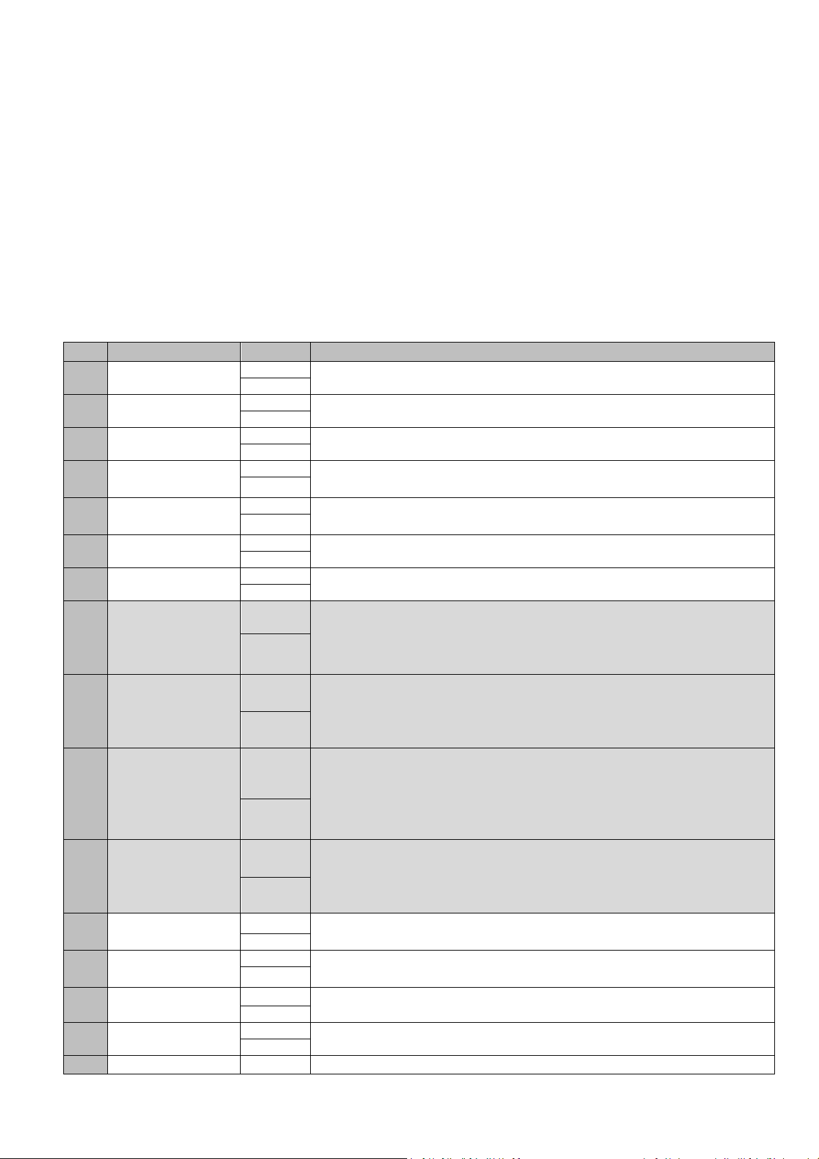
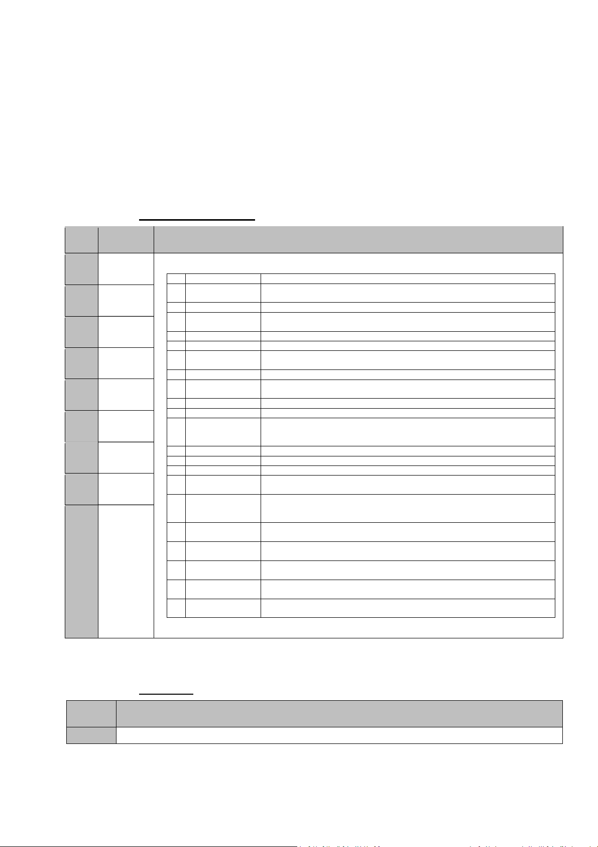
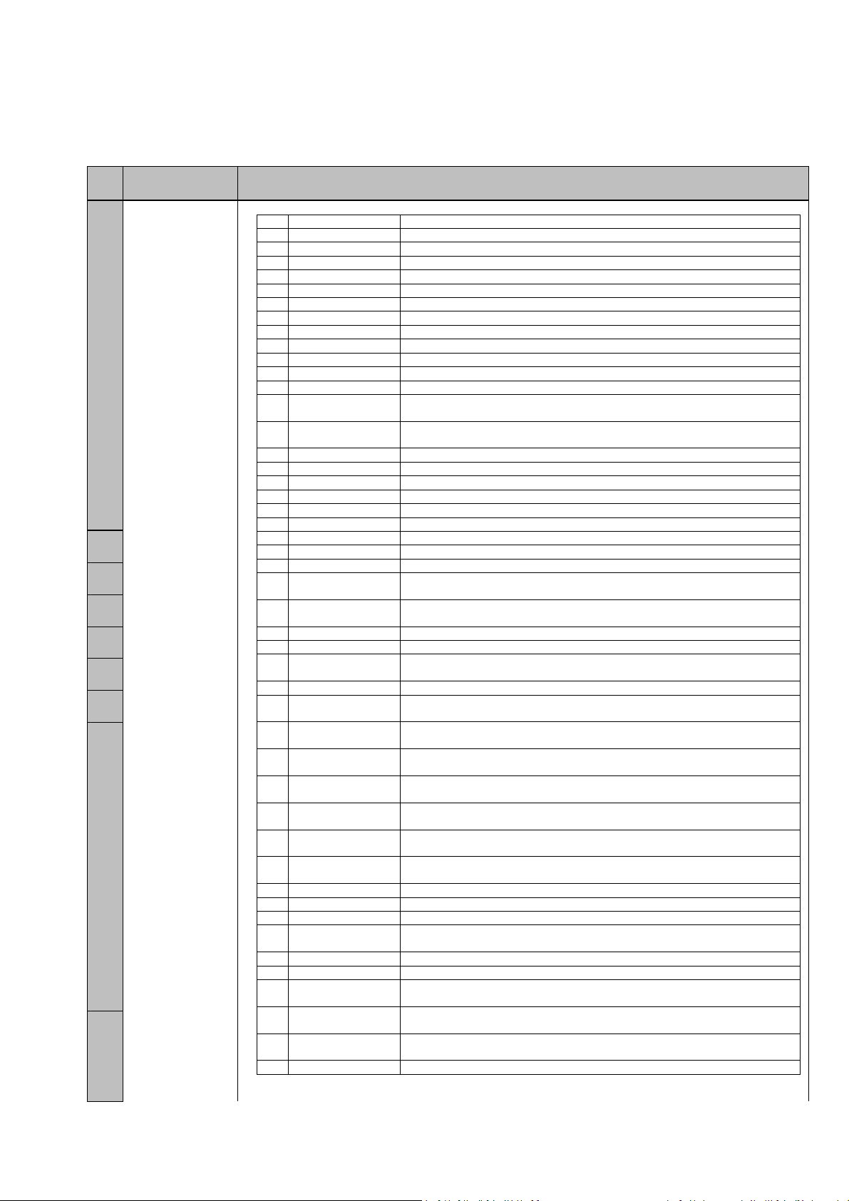
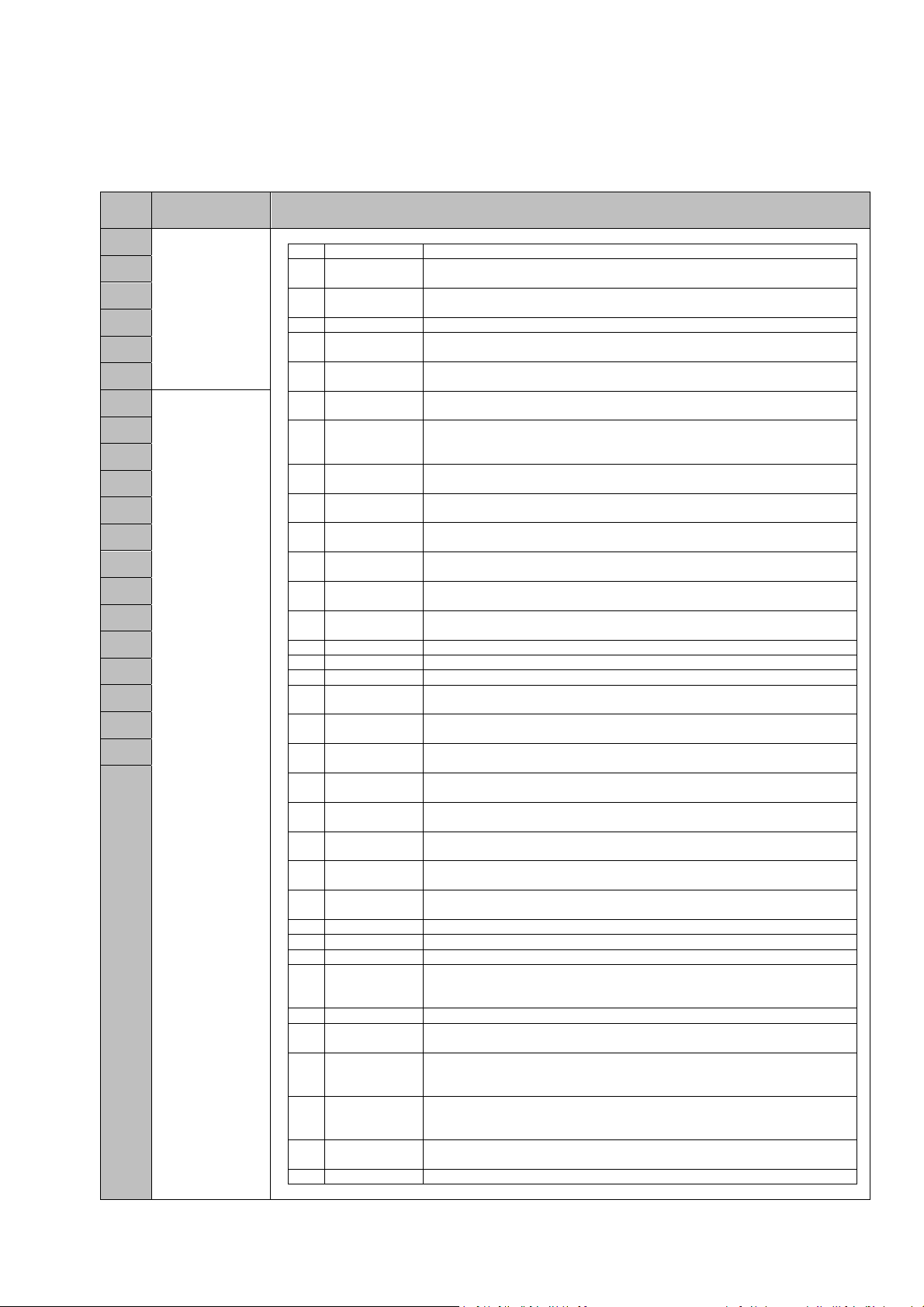
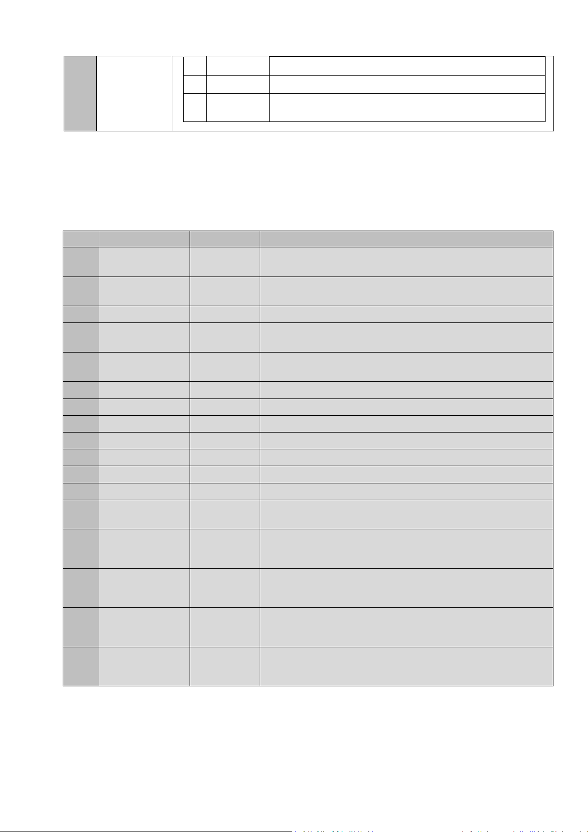
4.1 ON/OFF Option parameters
The ON/OFF parameters allows enable or disable control panel functions according to the needs of each
installation.
The parameters marked with the file in grey are only read parameters and they cannot be modified.
Num. Value On/off Description
Autoprogramming 0 – OFF Enables the autoprogramming function.
01
1 – ON
Auto close 0 – OFF Enables the autoclose function.
02
1 – ON
No stop on opening 0 – OFF Enables the non inversion at opening function.
03
1 – ON
Slow speed 0 – OFF Enables the slow speed.
04
1 – ON
Inhib.4cm
06
S.EDGE.CL
Dead man 0 – OFF Enables the deadman function.
07
SEC.CL inhibition 0 – OFF Enables the closing safety contact inhibition function.
08
FC.OP installed
09
FC.CL installed
0A
Open mechanical
0B
stop
Close mechanical
0C
stop
HALL mode
0D
Time mode 0 – OFF Enables the opertion by Time, i.e. the position is controlled by counting
0E
BackJump Open
0F
BackJump Close 0 – OFF Enables the Back Jump after the closing movement is complete.
10
Customization ID
11
0 – OFF Enables the safety edge inhibition function during the last 4cm of the
1 – ON
1 – ON
1 – ON
0 – OFF
1 – ON
0 – OFF
1 – ON
0 – OFF
1 – ON
0 – OFF
1 – ON
0 – OFF
1 – ON
1 – ON
0 – OFF
1 – ON
1 – ON
0 – OFF
closing movement.
Indicates whether, during programming, the panel has found and
memorised a limit switch on opening and, therefore, will act accordingly.
In most cases, it will open until this is found, adding pulses or time if
required.
Indicates whether, during programming, the panel has found and
memorised a limit switch on closure and, therefore, will act accordingly. In
most cases, it will close until this is found, adding pulses or time if
required.
Indicates whether, during programming, the panel has found and
memorised a mechanical stop on opening and, therefore, will act
accordingly. In most cases, it will open until the mechanical stop is found,
adding pulses or time if required. (Only available in control panels for DC
motors).
Indicates whether, during programming, the panel has found and
memorised a mechanical stop on closure and, therefore, will act
accordingly. In most cases, it will close until the mechanical stop is found.
(Only available in control panels for DC motors).
Enables the operation by pulses, encoder or Hall, i.e. the position is
controlled by counting pulses.
time.
Enables the Back Jump after the opening movement is complete.
Shows the customization number of the control panel.
10
COD. 1257066 Gamma VERSUS Manual v1.7
Page 11
GAMMA VERSUS MANUAL
1 – ON
Soft stop 0 – OFF Enables the soft stop function.
12
1 – ON
Radio CH1/2 config
13
Open slow start pt. 0 – OFF Enables slow starter before moving at normal speed at the start of
14
Close slow start pt.
15
Virtual ground ref.
16
Reference
17
Autosearch
SEC.CL
18
programmed
Substr. Bjump
19
PROG
Closing by CSEC 0 – OFF Enables the closure by security contact.
1A
HALL A type mode 0 – OFF Configures the HALL_A type (PNP/NPN) connected.
1B
HALL B type mode
1C
Limit switch DC Mot
1D
Limit switch AC Mot
1E
Limit opening
1F
detected
Limit closing
20
detected
HALLB IN available 0 – OFF Enables the second Hall input (HALL_B).
21
0 – OFF
1 – ON
1 – ON
0 – OFF
1 – ON
0 – OFF
1 – ON
0 – OFF
1 – ON
0 – OFF
1 – ON
0 – OFF
1 – ON
1 – ON
1 – ON
0 – OFF
1 – ON
0 – OFF
1 – ON
0 – OFF
1 – ON
0 – OFF
1 – ON
0 – OFF
1 – ON
Configures the radio mode:
1- ON: channel 1 open, channel 2 close;
2 - OFF: channel 1 start, channel 2 pedestrian
each maneuver of opening.
Enables slow starter before moving at normal speed at the start of
each maneuver of closing.
Enables the memorisation of the starting point of the programming
movement as the ground point. Most panels can only use this parameter
when operating by pulses. If this parameter is enabled, the closure
movement in programming will stop at this point. Where it is disabled, the
panel will not stop the closure movement until a closure synchronism is
received (end of run, mechanical stop, ALT, etc.), going past this point if
required. Likewise, if it is enabled, movement operations by pulses will be
counted on opening and if disabled they will be counted on closure.
Enables the automatic reference search. Where enabled and where, on
connecting the panel, it has lost position with regards to the reference/s,
the panel will automatically search for the reference without the need for
any pulses or transmitters.
Indicates if the closing security contact has been programmed during the
manoeuvre. The security contact inhibition during the closing movement
may not comply with regulations.
This refers to the special function of subtracting the number of pulses used
in closure Back Jump from the total number of pulses of the movement. In
other words, if the closure Back Jump is enabled, the panel will search for
the closure reference during the door programming process and will run
the closure Back Jump. The point where the door stops will be the virtual
ground point. It will not search for the ground reference again or run the
closure Back Jump. This only works with operations by pulses and where
the closure Back Jump is enabled. Once the panel has been
programmed, the closure Back Jump will be disabled. This must be taken
into account for later programming.
1- ON: PNP
0 - OFF: NPN
Configures the HALL_B type (PNP/NPN) connected.
1- ON: PNP
0 - OFF: NPN
Enables the detection of mechanical stops by current (DC motors).
Enables the detection of mechanical stops by current (AC motors).
Indicates whether, during programming, the panel has found and
memorized a mechanical stop on opening and, therefore, will act
accordingly. In most cases, it will open until the mechanical stop is found,
adding pulses or time if required.
Indicates whether, during programming, the panel has found and
memorized a mechanical stop on closure and, therefore, will act
accordingly. In most cases, it will close until the mechanical stop is found.
11
COD. 1257066 Gamma VERSUS Manual v1.7
Page 12

GAMMA VERSUS MANUAL
1 – ON
Lock mode
22
RBAND detected
23
Error info displayed 0 – OFF Enables the advanced level of errors/warnings displayed.
24
Pedestrian mode 0 – OFF Enables the pedestrian mode.
25
Motor outputs
26
inverted
Maximum speed
27
close
RBAND mode 0 – OFF Enables the RBAND mode.
28
RSENS mode 0 – OFF Enables the RSENS mode.
29
RSENS detected 0 – OFF Indicates the RSENS presence, if it has been detected on programming
2A
Time/HALL
2B
autoconfig
Half Dead man
2C
mode
Deadman if RSEC
2E
virgin
Autodetect
2F
OptoEdge IN1
Autodetect
30
OptoEdge IN2
Autodetect
31
OptoEdge IN3
Pre-FLASH option
91
RSENS Dynamic
92
Radio
0 – OFF
1 – ON
0 – OFF
1 – ON
1 – ON
1 – ON
0 – OFF Enables the sense inversion of motor outputs.
1 – ON
0 – OFF Enables the closing action at maximum speed.
1 – ON
1 – ON
1 – ON
1 – ON
0 – OFF
1 – ON
0 – OFF Enables the semi-deadman mode.
1 – ON
0 – OFF Enables dead man operating if a not programmed RSEC/R is detected.
1 – ON
0 – OFF Indicates that the IN1 input is configured as optical edge input.
1 – ON
0 – OFF
1 – ON
0 – OFF Indicates that the IN3 input is configured as optical edge input.
1 – ON
0 – OFF
1 – ON
0 – OFF
1 – ON
Indicates the RSENS lock configuration, if it has been detected on
programming mode.
Indicates the RBAND presence, if it has been detected on programming
mode.
mode.
Enables the automatic detection of time mode or Hall mode.
Indicates that the IN2 input is configured as optical edge input.
Enables the pre-flash function at the beginning of the manoeuvre.
Enables the dynamic adjustment mode the radio power for the RSENS.
Block On/off by
B1
password
Current blockage
B4
status
Recharge
B6
maneuver
Reverse strike at
BD
open
Absolut encoder
BE
mode
0 – OFF
1 – ON
0 – OFF
1 – ON
0 – OFF
1 – ON
0 – OFF Enables the reverse strike at open
1 – ON
0 – OFF Enables the operating by absolute encoder, that means that the position
1 – ON
Enables the blockage of the control panel via password (default value
0000).
Indicates if the control panel is blocked currently.
Enables the activation of the recharge maneuver during 3 seconds each
hour.
control is done by the absolute encoder control
12
COD. 1257066 Gamma VERSUS Manual v1.7
Page 13
GAMMA VERSUS MANUAL
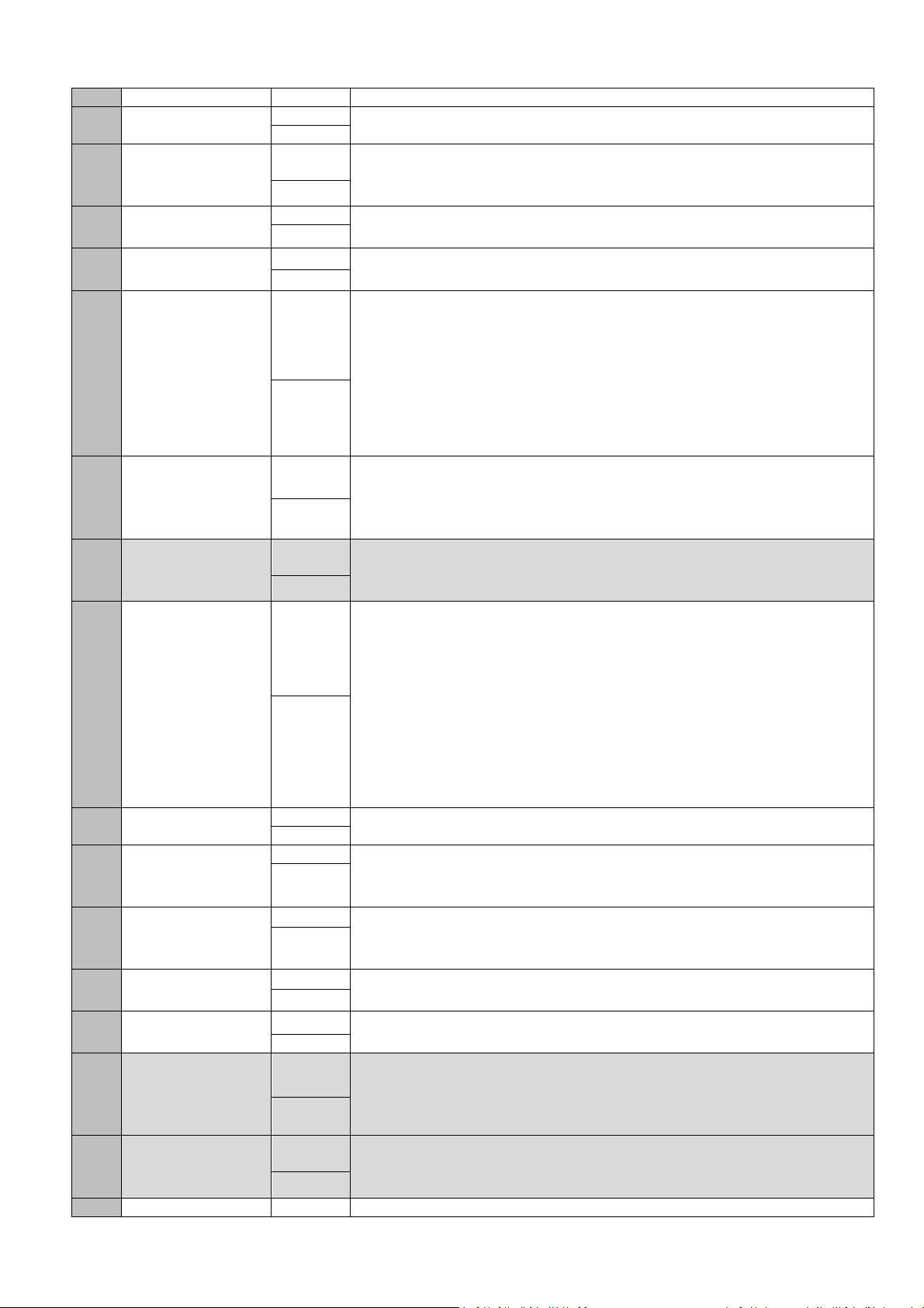
4.2 Numeric parameters
The numeric parameters allow defining different values of the control panels.
Note: When the V-DPLAY is used to read and/or configure parameters, it must be taken into account the
following. The V-DPLAY card only shows the two first digits of the most weight of the value. The real value
then will be the value showed on the display multiplied by a scale factor (DPLAY factor), indicated on the third
column of the table.
Real value = showed value * DPLAY factor
For example, if, for the 33 parameter, the display shows a 2, the real value will be 2*1000=2000.
Num. Numeric Factor
DPLAY
Time/pulse extra
5
inv.
Extratime
2D
Hydraulic mode
Max.num
movements
32
Opening stop point 1000 Stop point for the opening movement. In the case of operations by pulses,
1000 Time or pulse number added in each inversion.
1000 Extra time added after reference in hydraulic mode.
100000000 Limit number of panel movements as of which a special mode is enabled
33
Closing stop point 1000 Stop point for the closure movement. In the case of operations by pulses
34
Open slow start pt. 1000 Opening movement point where the slow speed is started in order to be
35
Close slow start pt. 1000 Closure movement point where the slow speed is started in order to be
36
Open Ped.stop
37
point
Close Ped.stop
38
point
Open Ped.slow
39
start pt.
Close Ped.slow 1000 Closing movement point where the slow speed is started in order to be
3A
1000 Stop point for the door during pedestrian opening movements.
1000 Stop point for the door during pedestrian closure movements.
1000 Opening movement point where the slow speed is started in order to be
Description
(operating or notification mode) in order to indicate that door maintenance
is required.
it indicates the number of pulses required to open from the ground
synchronism or closed door. The ground is normally point 0. In the case of
operations by time, the entire opening movement operation duration is
indicated. The panel returns the count in slow speed units, the programme
recalculates by adding the slow and normal speeds, multiplied by the
normal/slow ratio factor, as applicable.
and on most panels, this is position value 0. It will be of no use for
controlling the position of the door. In the case of operations by time, the
entire closure movement operation duration is indicated. The panel
returns the count in slow speed units, the programme recalculates by
adding the slow and normal speeds, multiplied by the normal/slow ratio
factor, as applicable.
able to slow down the door. In the case of operations by pulses, this is
normally the number of pulses with regards to the ground (closed door). In
the case of operations by time, the programmer will indicate the time from
the start of opening to this point.
able to slow down the door. In the case of operations by pulses, this is
normally the number of pulses with regards to the ground (closed door). In
the case of operations by time, the programmer will indicate the time from
the start of closure to this point.
able to slow down the door on pedestrian opening.
13
COD. 1257066 Gamma VERSUS Manual v1.7
Page 14

GAMMA VERSUS MANUAL
start pt. able to slow down the door on pedestrian opening.
SEC.CL inhib.point 1000 Point at which security contact inhibition is started during the closing
3B
BJump time/pulses
3C
open
Bjump time/pulses
3D
close
Max.time/pulses to
limit
3E
Inertia opening 1000 Number of pulses that the door has run with the motor at a standstill due to
1000 Distance run as opening Back Jump. It is normally a small distance in
1000 Distance run as closure Back Jump. It is normally a small distance in
1000 Number of pulses or time to be added to the opening and closure
3F
Inertia closing 1000 Number of pulses that the door has run with the motor at a standstill due to
40
Autoclose value 10 Auto-close time.
41
Inhib.zone start
42
point
Imax normal speed 10 Maximum current measured during programming at normal speed. This
1000 Size of the inhibition zone of any safety device at the end of the maneuver.
43
Imax low speed 10 Maximum current measured during programming at slow speed. This will
44
Current margin 10 Level of sensitivity with which an obstacle due to overcurrent will be
45
Norm/Low speed
46
factor
Max.security
detections
10 Ratio between the normal and slow speed of the door. The higher the
10 Number of security trigger reversals permitted before auto-close is
47
Max.autotests
48
before err.
Time to close by
49
SEC.CL
Electrolock time 10 Activation time of the electrolock.
4A
Courtesy light time 10 Activation time of the garage light.
4B
Flash frequency 10 Flash period time.
4C
Pre-flash time 10 Pre-flash time.
4D
Max.sequence
4E
time
Press.time to
4F
deadman
Panic signal period 10 Activation time of the panic signal.
50
Integrator value
51
TH1
10 Number of autotest repeats allowed before going out a nd showing error.
1000 Waiting time before doing the closing movement by security contact.
10 Maximum maneuver time.
10 Needed pushing time of the Open or Close Pushbutton to enter to
1000 Integrator threshold 1 value (internal limit switch detection).
movement.
pulses or time.
pulses or time.
movement to search for the reference, i.e. to reach the end of run or
mechanical stop memorised during programming.
inertia during opening operations.
inertia during closure operations.
will normally be the current limit that the panel will accept during
operations at normal speed.
normally be the current limit that the panel will accept during operations at
slow speed.
detected during normal operations. In other words, the value that is added
to the memorised current curve and that stipulates the current limit
permitted at each movement point (motor power).
value, the lower speed.
inhibited. Where the door exceeds this maximum number of consecutive
closure reversals without being able to close completely, the auto-close
function will be disabled.
deadman mode.
14
COD. 1257066 Gamma VERSUS Manual v1.7
Page 15

GAMMA VERSUS MANUAL
A
Integrator value
52
TH2
RSENS
53
inhib.margin
Current margin in
93
PROG
AC Motor speed
94
regul.
C Motor LOW sp.
95
Regul.
Password value 100(*) Password's value for the blockage of the control panel.
B2
Inversion time by
B3
SEC.CL
Traffic control
B5
mode
(*) The password value is composed of 4 digits so that it can take values from 0000 to 9999. As it is modified the
V-DPLAY accessory, first introduce the first 2 digits higher (P1) and then the other 2 digits (P2).
1000 Integrator threshold 2 value (internal limit switch detection).
10 Inhibition zone of the closing maneuver of RSENS.
10 Level of sensitivity with which an obstacle due to overcurrent will be
detected during programming.
10 AC motor power regulation value.
10 AC motor power regulation value in slow speed.
100 Inversion time after closing security detection.
10 Indicates the value of the traffic control mode.
15
COD. 1257066 Gamma VERSUS Manual v1.7
Page 16
GAMMA VERSUS MANUAL
4.3 Switch parameters
The switch parameters allow assigning different functions to each option of the switch. Each switch input
(option) can have different values; they are indicated on the third column of the following table.
If there is a physical switch on the board with one of the following parameters associated, it will be taken into
account always. That means, if option 1 of the physical switch on the board has assigned the function
Autoprogramming and it is at ON, and the parameter 01 (Autoprogramming) is at OFF, the control panel will
take the value Autoprogramming at ON.
4.3.1 Switch parameters
Num Switch Available values - description
54
55
56
57
58
59
5A
5B
5C
Switch 1
Switch 2
Switch 3
Switch 4
Switch 5
Switch 6
Switch 7
Switch 8
Switch 9
0 NO FUNCTION The switch has not got a defined function
1 AUTOPROGRAM
MING
2 AUTOCLOSE Enables the autoclose function
3 NOSTOP ON
OPENING
4 SLOW SPEED Enables the slow speed
5 ELECTROLOCK Enables the electrolock function
6 INH.4CM
S.EDGE.CL
7 DEAD MAN Enables the deadman function
8 SEC.CL
INHIBITION
9 RSENS CONFIG Enables the RSENS mode.
10 RBAND CONFIG Enables the RBAND mode.
11 TIME/HALL
CONFIG
12 SEC.CL TEST Enables the closing security contact autotest
13 SEC.OP TEST Enables the opening security contact autotest
14 PRE-FLASH Enables the pre-flash function
15 CLOSING BY
SEC.CL
16 COURTESY
LIGHT/FLASH
17 TEST PRESSURE
SWITCH
18 INH.OP.PRESSU
RE SW
19 SEC.CL OPEN
REF
20 AUTO
DETECT.FC.
21 REVERSE
STRIKE
Enables the autoprogramming function
Enables the non inversion at opening function
Enables the safety edge inhibition function during the last 4cm of the closing
movement.
Enables the closing safety contact inhibition function.
Configures:
1 - ON: Time function;
2 - OFF: HALL function
Enables the closing security contact
Configures:
1 - ON: garage light output;
2 - OFF: flash output
Configuration test pressure switch function.
Enables the inhibition function of the pressure switch during the opening
sequence.
Configuration of close security contact as opening reference function.
Configuration of the autodetection of limit switches by current (AC motors).
Configuration of the reverse strike at open.
4.3.2 Jumpers
Jumper Function
JP If cut off does not allows Side-prog programming
COD. 1257066 Gamma VERSUS Manual v1.7
16
Page 17
GAMMA VERSUS MANUAL
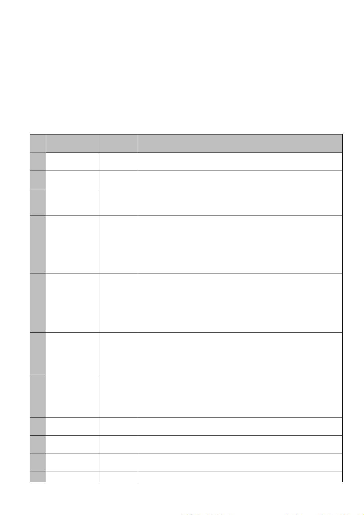
4.4 Input parameters
The input parameters allow configuring each available input of the control panel. Each input can have different
values; they are indicated on the third column of the following table.
Num Inputs Available values - description
0 NO FUNCTION The input has not got a defined function.
1 S.EDGE.CL Closing safety edge input (8k2) .
2 S.EDGE.OP Opening safety edge input (8k2).
5 FC.OP M1 M1 motor opening limit switch input (NC).
6 FC.OP M2 M2 motor opening limit switch input (NC).
7 FC.CL M1 M1 motor closing limit switch input (NC).
8 FC.CL M2 M2 motor closing limit switch input (NC).
9 SEC.OP Opening security contact input (NC).
10 SEC.CL Closing security contact input (NC).
11 STOP Stop pushbutton input (NC).
5E
5F
60
61
62
63
64
65
66
IN 1:IN10
12 START Start pushbutton input (NO).
13 OPEN Open pushbutton input (NO).
14 CLOSE Close pushbutton input (NO).
PEDESTRIAN
15
START Pedestrian pushbutton input (NO).
PEDESTRIAN
16
OPEN Open pedestrian pushbutton input (NO).
17 DEAD MAN OPEN Open pushbutton input in deadman mode (NO).
18 DEAD MAN CLOSE Close pushbutton input in deadman mode (NO).
19 DEAD MAN OP-CL Start pushbutton input in deadman mode (NO).
20 HALL_A MOTOR 1 HALL A for M1 motor input
21 HALL_B MOTOR 1 HALL B for M1 motor input
22 HALL_A MOTOR 2 HALL A for M2 motor input
23 HALL_B MOTOR 2 HALL B for M2 motor input
24 ZERO CROSS Configuration input as zero pass.
25 PROG Programming pushbutton input PROG.
26 CURRENT MOTOR 1 Configuration input as current motor 1.
27 CURRENT MOTOR 2 Configuration input as current motor 2.
28 SEC.OP Magnetic opening security contact input (connected to MTC).
29 RADIO START Start pushbutton via radio input (NO).
30 STOP BY
TEMPERATURE
31 SEC.CL Magnetic closing security contact input (connected to MTC).
32 SEC.OP
AUTOTEST
33 SEC.CL
AUTOTEST
34 S.EDGE.CL
AUTOTEST
35 S.EDGE.OP
AUTOTEST
36 RSENS
DETECTION
37 RBAND OPEN
DETECT
38 RBAND CLOSE
DETECT
39 STOP N.O. STOP input (NO)
40 OPTO EDGE.CL Closing optical safety edge input.
41 OPTO EDGE.OP Opening optical safety edge input.
42 PRESSURE
SWITCH
43 AUTOEDGE.CL Closing automatic 8K2/OPTO safety edge input.
44 AUTOEDGE.OP Opening automatic 8K2/OPTO safety edge input.
45 COURTESY LIGHT
ON
46 OPEN SLOW
SPEED REF
47 CLOSE SLOW
SPEED REF
48 OPEN INSIDE Configuration input as open from inside.
Temperature stop input (thermal).
Opening security contact with autotest function input (NC). If this input is
used, an autotest output ready to perform autotest functions must be used.
Closing security contact with autotest function input (NC). If this input is used,
an autotest output ready to perform autotest functions must be also used.
Closing safety edge with autotest function input (NC). If this input is used, an
autotest output ready to perform autotest functions must be also used.
Opening safety edge with autotest function input (NC). If this input is used,
an autotest output ready to perform autotest functions must be also used.
Configuration input as RSENS detection.
Configuration input as RBAND opening detection.
Configuration input as RBAND closing detection.
Configuration input as pressure switch
Courtesy light activation input.
Configuration input as opening slow speed entering reference.
Configuration input as closing slow speed entering reference.
17
COD. 1257066 Gamma VERSUS Manual v1.7
Page 18

GAMMA VERSUS MANUAL
67
M1
current/zerocross
68
IN
M2 current IN
69
START
6A
pushbutton IN
STOP
6B
pushbutton IN
OPEN
6C
pushbutton IN
CLOSE
6D
pushbutton IN
PROG
6E
pushbutton IN
(HALL A) IN
6F
OPTO EDGE IN
70
(DCS CH1) IN
71
(DCS CH2) IN
72
Low Voltage IN
73
(Motion C1) IN
74
(Motion C2) IN
75
(Motion C3) IN
76
(Motion C4) IN
77
18
COD. 1257066 Gamma VERSUS Manual v1.7
Page 19
GAMMA VERSUS MANUAL
4.5 Output parameters
The output parameters allow configuring each available input of the control panel. Each output can have
different values; they are indicated on the third column of the following table.
Num Output Available values - description
78
79
OUT 1:OUT 6
7A
7B
7C
90
A1
A2
A3
A4
A5
A6
A7
A8
A9
AA
AB
AC
AD
AE
(TL-CARD-V)
OUT
AF
0 ALWAYS OFF The output has not got a defined function
1 COURTESY
LIGHT LEVEL
2 COURTESY
LIGHT PULSE
3 FLASH Flash output
4 FLASH+COUR
TESY LIGHT
5 ELECTROLOCK Electrolock output
6 ELECTROBRA
KE
7 CLOSE
AUTOTEST
SIGNAL
8 OPENING
SEQ. START
9 OPENING
SEQUENCE
10 CLOSING
SEQ. START
11 CLOSING
SEQUENCE
12 ERROR
SIGNAL
13 PEDESTRIAN
SEQUENCE
14 PANIC SIGNAL Active output when panic signal detection
15 GREEN LIGHT Green traffic light control output
16 RED LIGHT Red traffic light control output
17 INSIDE
GREEN LIGHT
18 INSIDE RED
LIGHT
19 OUTSIDE
GREEN LIGHT
20 OUSIDE RED
LIGHT
21 INTRUSIVE
SIGNAL
22 S.EDGE
ACTIVE
23 SEC.OP
ACTIVE
24 SEC.CL
ACTIVE
25 FC.OP ACTIVE Active output when opening limit switch detection
26 FC.CL ACTIVE Active output when closing limit switch detection
27 ALARM Active output when alarm signal detection
28 MAX.
NUM.SEQUEN
CES
29 ALWAYS ON Output always active
30 MOTOR
RUNNING
31 LOW
BATTERY
SIGNAL
32 OPEN
AUTOTEST
SIGNAL
33 ELECTROMAG
NET
34 BOLLARD Configuration output as bollard control signal.
Garage light level output (duration = maneuver time + programmed time)
Garage light pulse output (duration = programmed time)
Flash+courtesy light by level output.
Electrobrake control output
Closing security contact autotest output
Active output right at the beginning of the opening operation
Active output during all the opening operation
Active output right at the beginning of the closing operation
Active output during all the closing operation
Active output when error detection
Active output during pedestrian mode
Green inside traffic light control output (traffic control mode)
Red inside traffic light control output (traffic control mode)
Green outside traffic light control output (traffic control mode)
Red outside traffic light control output (traffic control mode)
Intruder detection function output
Active output when safety edge detection
Active output when opening security contact detection
Active output when closing security contact detection
Active output when the maximum number of maneuvers is exceeded
Active output at any door movement
Active output when low battery detection
Opening security contact autotest output
Configuration output as electromagnet control.
19
COD. 1257066 Gamma VERSUS Manual v1.7
Page 20
GAMMA VERSUS MANUAL
35 BOLLARD
LIGHT
36 BOLLARD RED
LIGHT
37 BOLLARD
WARNINGLIG
B0
HT
4.6 Status parameters
The status parameters indicate the state of the maneuver, last errors or control panel versions. These
parameters are only read parameters and they cannot be modified.
Num. Parameters Factor DPLAY Description
Door pos in HALL
7D
mode
Door pos in time
7E
mode
Control panel status
7F
Control panel last
80
error
Number of
81
sequences
Variator SW version
82
Software version
96
EEPROM version
97
Serial number
98
Production ID
99
Panel last Problem
9A
Panel last Warning
9B
Current
9C
Consumption
101-104 TL-CARD-
9D
V Status
1000 Shows the door position when HALL mode
1000 Shows the door position when time mode
10 Shows the control panel state ( open, lost, closed)
10 Shows the value of the last error detected
100000000 Shows the number of memorized maneu vers
1000 Shows the list version of the parameters from the control panel
1000 Shows the software version of the control panel
1000 Shows the memory data version
100000000 Shows the serial number of the control panel
100000000 Shows the production number of the cont rol panel
10 Shows the last problem detected
10 Shows the value of the last warning detected
10 Shows the value of the current consumption
10 Shows if the TL-CARD-V with the 101, 102, 103, 104 output is
Configuration output as a crown of light bollard.
Configuration output as red traffic light bollard mode.
Configuration output as warning traffic light bollard mode.
connected.
111-114 TL-CARD-
9E
V Status
121-124 TL-CARD-
9F
V Status
131-134 TL-CARD-
A0
V Status
10 Shows if the TL-CARD-V with the 111, 112, 113, 114 outputs is
connected.
10 Shows if the TL-CARD-V with the 121, 122, 123, 124 outputs is
connected.
10 Shows if the TL-CARD-V with the 131, 132, 133, 134 outputs is
connected.
20
COD. 1257066 Gamma VERSUS Manual v1.7
Page 21
GAMMA VERSUS MANUAL
5. LIGHT INDICATORS
Function Indicates Default value
ON Power supply Normally light on
STOP/ERROR Operating warning or error Normally light off
PROG Programming mode Normally light off
INXX Input activated Normally light off
OUTXX Output activated Normally light off
6. DISPLAY MESSAGES
6.1 Serious errors
Errors associated with the security of the installation or equipment malfunction. These errors must be
resolved always.
ER02
ER08
ER09
ER12
ER13
ER16
ER19
ER20
ER21
ER22
ER23
ER26
Error Description Solution
INT. ERROR Internal error
HA ERROR Hall A error
PROG TIME MAX Hall B error Program a maneuver below the
S.EDGE.CL ERROR Closing safety edge error Verify the security edge band
S.EDGE.OP ERROR Opening safety edge error Verify the security edge band
TEMP ON Motor temperature sensor
activated
TEST.CL ERROR Closing auto test error Verify that the security device connected
TEST.OP ERROR Opening auto test error Verify that the security device connected
RSENS NC WHEN
PROG
RSENS NOT FOUND Control panel programmed with
RSENS PROG ERROR RSENS programming error, are R
STOP Control panel stopped by an STOP Verify that the STOP input has been
Control panel programmed without
RSENS connected
RSENS connected and now it is
not connected
and T paired?
Go to the technical service
Verify the hall A input connections
maximum allowed time
connections when closing
connections when opening
Verify the motor state and the
temperature sensor connection
to the security connection when closing
is in good conditions and correctly
installed
to the security connection when opening
is in good conditions and correctly
installed
Connect the RSEC card and program the
control panel again
Program the control panel again without
RSEC or connect the RSEC again that
was programmed to the control panel
previously
Program the transmitter RSENS to the
RSEC receiver card
activated
21
COD. 1257066 Gamma VERSUS Manual v1.7
Page 22
ER28
ER29
ER30
ER31
ER32
ER33
ER36
ER39
ER41
GAMMA VERSUS MANUAL
INTERNAL ERROR Internal control panel error
DOOR LOCKED RSENS Closed door latch Open the door's latch before the opening
RBAND NOT FOUND Control panel programmed with
RBAND connected and now it is
not connected
RBAND NC WHEN
PROG
FC NOT LEARNT End of course learning error
ERROR SYNC RSENS Synchronization error between the
RSENS RADIO ERROR Detection through opening current Verify the batteries of the RSENS emitter
CTROL PANEL
BLOCKED
ERROR ABSOLUT
ENCODER
Control panel not programmed
with RBAND connected
receiver and the transmitter
Control panel cannot enter
programmation because it is
blocked.
Absolut encoder not found or
returning a mistake
Go to the technical service
manoeuvre
Program the control panel again without
using RBAND or connect the RBAND
that was connected to the control panel
previously
Connect the RBAND card and program
the control panel again
Verify the intern motor limit switches
Program the transmitter RSENS to the
RSEC receiver card
id they are charged, verify the radio
signal with the Check function
Enter the password with V-DPLAY or
VERSUS-PROG for unlocking the control
panel.
Verify the connection of the absolute
encoder
6.2 Minor errors
Errors that do not inhibit the operation of the control panel but it is recommended to solve for a good
operating.
ER01
ER07
ER24
ER25
Error Description Solution
NOT PROGRAMMED Control panel not programmed
REF. NOT FOUND Any reference has been reached Define a reference when programming
FCO Control panel programmed with
RSENS but without FCO
RSENS LOW BATTERY RSENS low battery Verify the batteries of the RSENS
Program the control panel again
the control panel (limit switch,
mechanical stop, etc...)
A limit switch should be installed to
improve the installation with the RSENS
system
transmitter
22
COD. 1257066 Gamma VERSUS Manual v1.7
Page 23

GAMMA VERSUS MANUAL
6.3 Warnings
Informative messages from the control panel.
WR03
WR04
WR05
WRO6
WR10
WR11
WR14
WR15
WR17
WR18
WR27
WR34
WR35
WR37
WR38
Error Description Solution
FC.CL M1 NOT FOUND Closing end of course Motor 1 not
found when expected
FC.CL M2 NOT FOUND Closing end of course Motor 2 not
found when expected
FC.OP M1 NOT FOUND Opening end of course Motor 1 not
found when expected
FC.OP M2 NOT FOUND Opening end of course Motor 2 not
found when expected
S.EDGE.CL ON Closing safety edge activated Verify that the security edge activation
S.EDGE.OP ON Opening safety edge activated Verify that the security edge activation
C.SEC.CL ON Closing security contact activated Verify that the security edge activation
C.SEC.OP ON Opening security contact activated Verify that the security edge activation
MAG.DETEC ON Magnetic closing security activated Verify that the security edge activation
RSENS ON RSENS security activated Verify that the security edge activation
C.SEC.M ON Magnetic security contact
activated
ERROR RADIO
DESCRYPT
ERROR RADIO RTDS The radio signal received is very
S.OPTOEDGE.CL ON Closing optical safety edge
S.OPTOEDGE.OP ON Opening optical safety edge
Receiving not programmed
transmitters from another
customer or installer
low
activated
activated
Verify the limit switch installation when
motor 1 is closing
Verify the limit switch installation when
motor 2 is closing
Verify the limit switch installation when
motor 1 is opening
Verify the limit switch installation when
motor 2 is opening
was produces by an obstacle
was produces by an obstacle
was produces by an obstacle
was produces by an obstacle
was produces by an obstacle
was produces by an obstacle
Verify that the security edge activation
was produces by an obstacle
Verify that in the installation there are no
emitters of another client/ installer
activated with our control panel
Verify the installation and the radio signal
Verify that the security edge activation
was produces by an obstacle
Verify that the security edge activation
was produces by an obstacle
WR40
PRESSURE SW ON Pressure switch activation
(hydraulic motor).
Verify that the pressure switch activation
was produced by an obstacle.
23
COD. 1257066 Gamma VERSUS Manual v1.7
Page 24
GAMMA VERSUS MANUAL
7. VERSUS FUNCTIONS
7.1 Autoprogramming function
Model
Associated
parameters
Description
Configuration
Operating
Notes
All
ID Description Type
P01 Autoprogramm ng ON/OFF
The autoprogramming function allows programming the control panel maneuvers by
means of a single user action (by pressing control panel button START/OPEN or
transmitter).
To enable the autoprogramming function, it is needed to set to ON the P01 configuration
parameter by means of a VERSUS-PROG programming tool. It is also possible to enable
or disable this function by setting the “Autoprogramming ON/OFF” function to an option
switch.
If the autoprogramming function is enabled when the maneuver is programmed a single
user action is needed. After this user action, the control panel automatically executes the
opening and closing maneuvers. During these maneuvers the control panel searches
and stores the opened/closed point references. Finally, the control panel exits the
programming mode automatically.
The autoprogramming function can not be enabled if it is not possible to find an
opened/closed point reference (this means, if no limit switches inputs or mechanical stop
are present).
If this function is enabled, after the programming sequence the autoclosing timeout is set
by default to 30 seconds. In addition the pedestrian maneuver is set by default to 1/3 of
the main maneuver. Finally, in case of slow speed mode, the slow speed run will be a
15% of the main maneuver.
Autoclose30s
Slowspeed
opening15%
Slowspeedclosing
15%
Pedestrian1/3
24
COD. 1257066 Gamma VERSUS Manual v1.7
Page 25
GAMMA VERSUS MANUAL
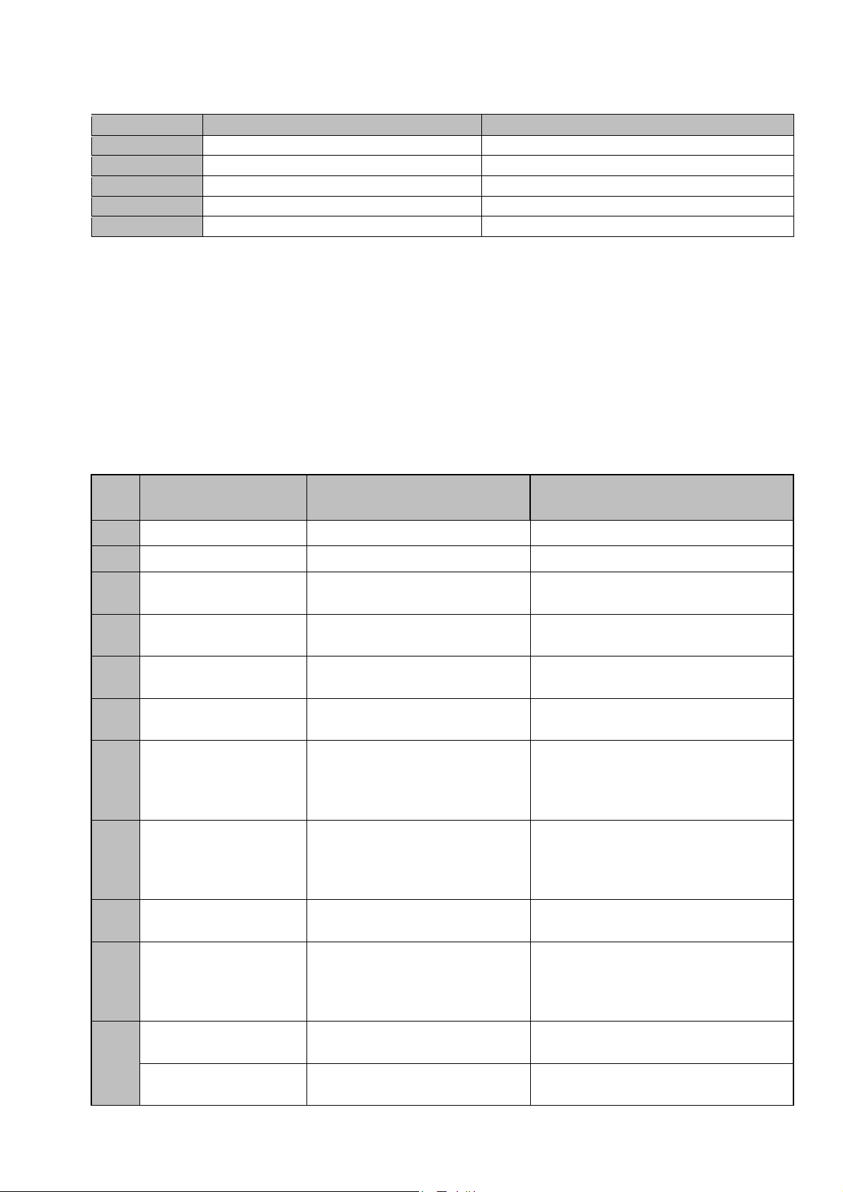
7.2 Hall or time mode function
Model
Associated
parameters
Description
Configuration
Operating
Notes
Time mode (all) and Hall mode (M20,M30)
ID Description Type
P0D HALL mode ON/OFF
P0E Time mode ON/OFF
P33 Opening stop point NUMERIC
P34 Closing stop point NUMERIC
VERSUS control panels can work either by time or by Hall.
To enable Time or Hall modes it is necessary to set to ON the associated parameters
(P0D or P0E parameters) by means of a VERSUS-PROG programming tool. It is also
possible to enable or disable these functions by setting the mode Time/HALL function to
an option switch. Enabling Time mode implies disabling the Hall mode and vice versa.
After configuring the working mode, the control panel will use Time or Hall signal as a
position reference.
The main maneuver parameters that define its duration are the P33 and P34
configuration parameters. The opened and closed positions are the starting points and
they always take the 0 value. P33 parameter configures the opening stop point (opening
maneuver duration) and the P34 parameter configures the closing stop point (closing
maneuver duration).
According to the selected working mode, all the position parameters will use a certain
position units. In case of Hall mode, these units are pulses and in case of time mode,
seconds or milliseconds will be used. By means of a VERSUS-PROG programming tool
it is possible to see these position units.
P33Openingstoppoint
Openingstarting
point(always0)
Closingstarting
point(always0)
P34Closingstop
point
25
COD. 1257066 Gamma VERSUS Manual v1.7
Page 26
GAMMA VERSUS MANUAL
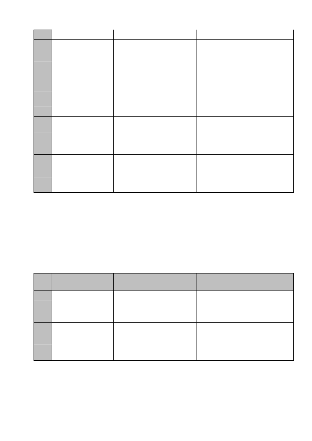
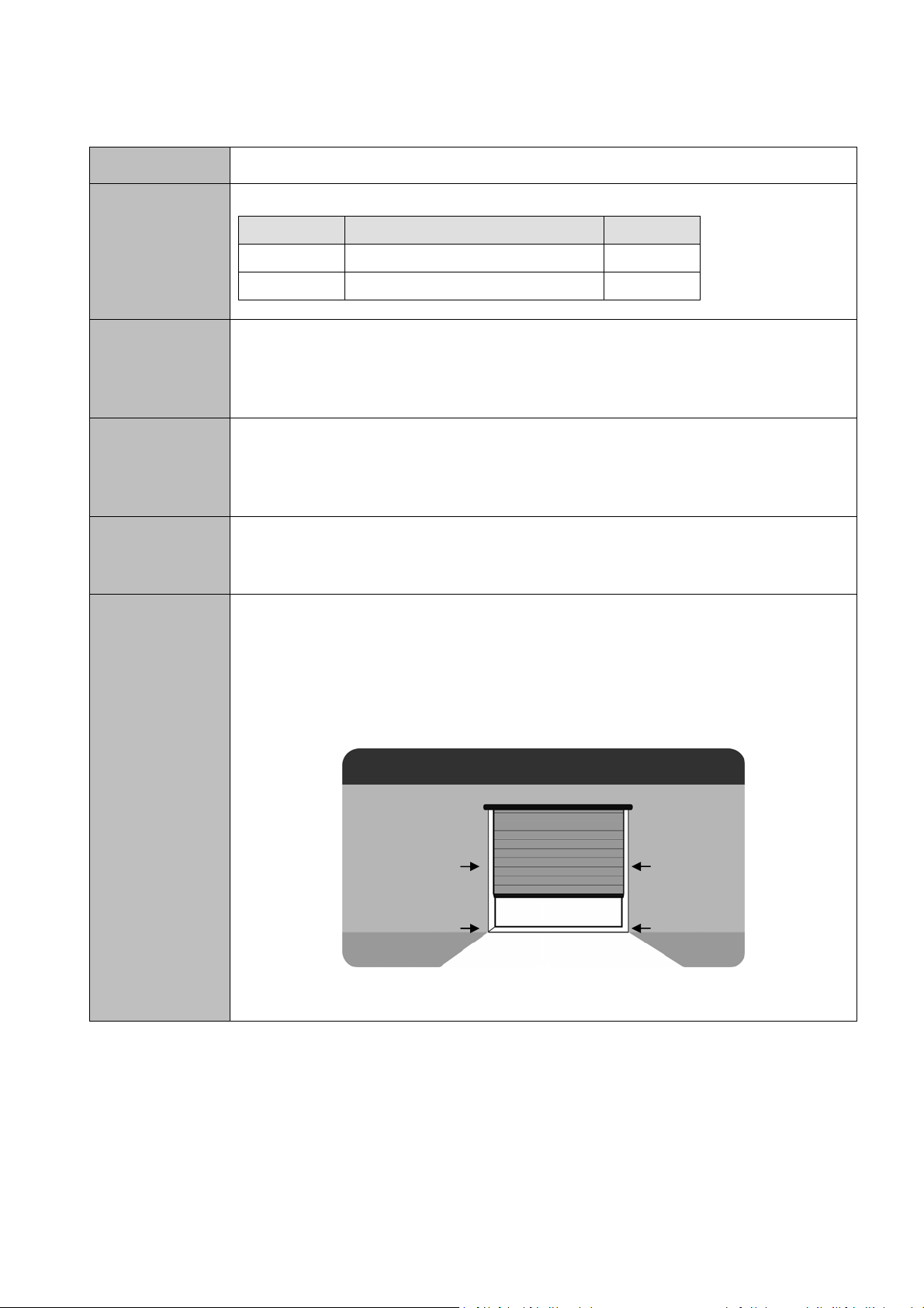
7.3 Pedestrian function
Model
Associated
parameters
Description
Configuration
Operating
Notes
All
ID Description Type
P37 Open Ped. stop point NUMERIC
P38 Close Ped. stop point NUMERIC
VERSUS control panels can control 2 types of maneuvers: main and pedestrian
maneuvers. The aim of the pedestrian maneuver is opening a portion of the door in order
to let enough space to allow entering/exiting a person, without the need to open the hole
door.
The pedestrian mode is enabled by default and it is necessary to program its maneuver
in the same way the main maneuver is programmed (except if autoprogramming function
is enabled). The only difference is that the pushbutton needed to program the pedestrian
maneuver is the PEDESTRIAN pushbutton.
After programming the pedestrian maneuver, if a PESESTRIAN pushbutton is pressed
the pedestrian maneuver is executed and the door opens the portion of the programmed
aperture.
The pedestrian maneuver parameters that define its duration are the P37 and P38
configuration parameters. The opened and closed positions are the starting points and
they always take the 0 value. P37 parameter configures the opening stop point (opening
pedestrian maneuver duration) and the P38 parameter configures the closing stop point
(closing pedestrian maneuver duration).
P37OpenPed.stoppoint
OpenPed.starting
point(always0)
ClosePed.
startingpoint
(always0)
P38ClosePed.
stoppoint
26
COD. 1257066 Gamma VERSUS Manual v1.7
Page 27
GAMMA VERSUS MANUAL
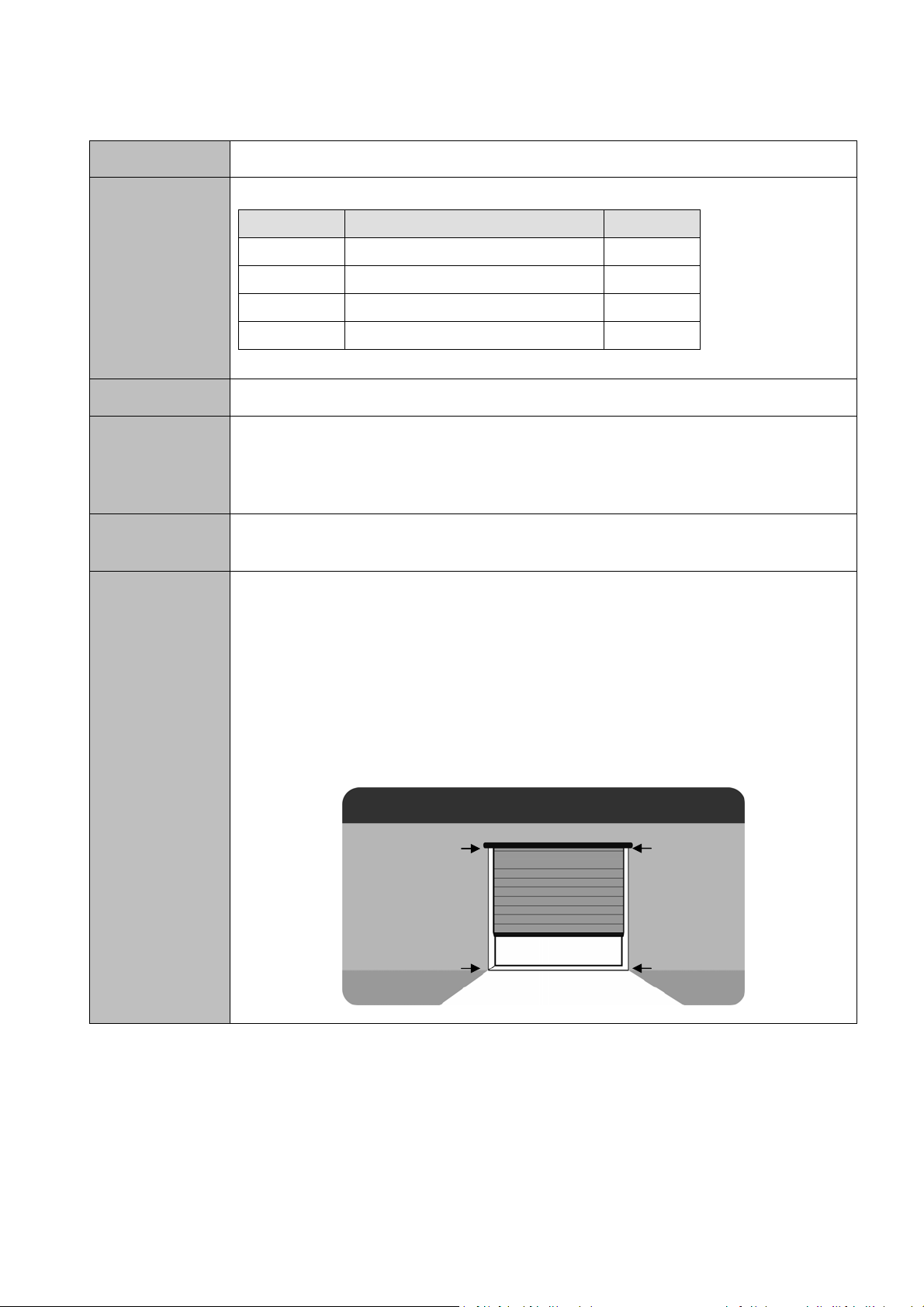
7.4 Speed regulation and slow speed mode in AC motors function
Model
Associated
parameters
Description
Configuration
M20,M30
ID Description Type
P04 Slow speed ON/OFF
P46 Norm/Low speed factor NUMERIC
P94 AC Motor speed regulation NUMERIC
P95 AC Motor low speed regulation NUMERIC
P35 Open slow start pt. NUMERIC
P36 Close slow start pt. NUMERIC
P39 Open Ped. Slow start pt. NUMERIC
P3A Close Ped. Slow start pt. NUMERIC
Some VERSUS control panels for AC motors allow controlling motor speed during the
maneuver (normal speed regulation and slow speed mode).
By default, the normal speed regulation function is enabled. This configuration parameter
P94 allows modifying the normal speed regulation and it can take any value from 10% to
100%. The smaller the value, the slower the normal speed. This configuration parameter
can be configured by means of VERSUS-PROG programming tool.
To enable slow speed mode it is necessary to set to ON the associated P04 parameter
by means of a VERSUS-PROG programming tool. It is also possible to enable or
disable this function by setting the slow speed mode ON/OFF function to an option
switch.
There are two configuration parameters that allow modifying the slow speed: The P46
parameter is used to adjust, in a coarse way, the normal/slow speed factor and it can
take values from 0 to 255. The higher the value, the slower the slow speed according to
the normal speed. The P95 parameter allows modifying the slow speed regulation, doing
a fine adjustement, and it can take values from 0% to 90%. The higher the value, the
slower the slow speed. Depending on the AC motor model these parameters will be
needed to be adjusted in order to obtain the desired slow speed. This adjustment must
be done with the AC motor connected to the door (full charge).
27
COD. 1257066 Gamma VERSUS Manual v1.7
Page 28
GAMMA VERSUS MANUAL
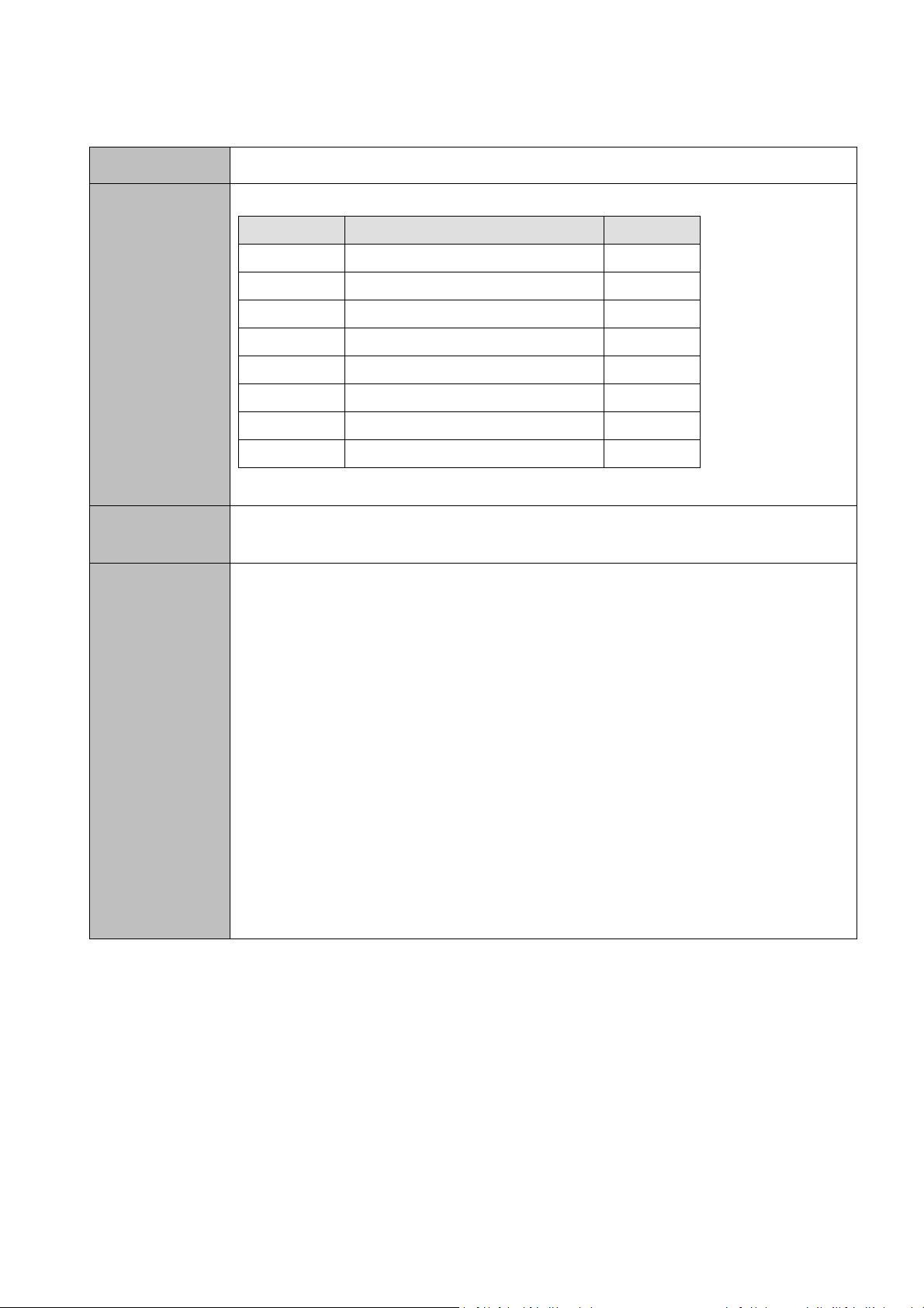
Operating
Notes
After configuring the parameters of normal speed regulation, these will be taken into
account during the next maneuvers.
After enabling the slow speed mode, a new programming sequence will be needed for
main and pedestrian maneuvers. In this programming sequence, user will define the
slow speed maneuver zones.
The slow speed maneuver parameters that define its duration are P35 and P36
configuration parameters for the main maneuver and P39 and P3A configuration
parameters for the pedestrian maneuver.
P35 and P39 parameters configure the slow speed starting opening point and the P36
and P3A parameters configure the slow speed starting closing point. To define these
points it is necessary to press the START or PEDESTRIAN pushbutton during the
programming sequence (except if autoprogramming function is enabled). For example,
when programming the opening maneuver, the first press starts the maneuver in normal
speed and the second press starts the slow speed maneuver and this second defines
the slow speed starting point.
- Main maneuver slow speed points:
OPENINGSLOWSPEED
ZONE
P35Openslowstart
point
OPENINGNORMALSPEED
ZONE
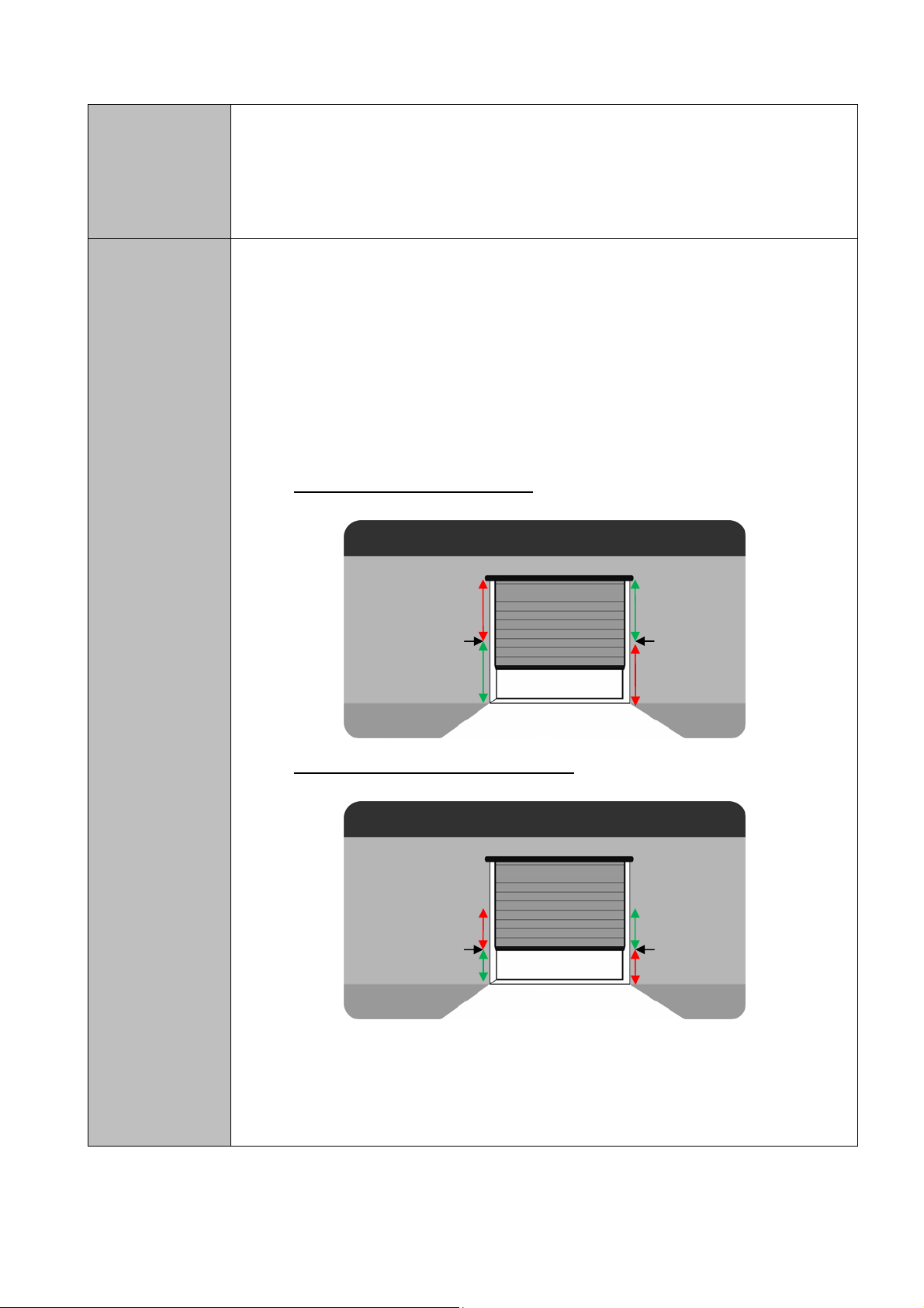
- Pedestrian maneuver slow speed points:
OPENINGPED.SLOWSPEED
ZONE
P39OpenPed.slowstart
point
OPENINGPED.NORMALSPEED
ZONE
CLOSINGNORMALSPEED
ZONE
P36Closeslowstart
point
CLOSINGSLOWSPEED
ZONE
CLOSINGPED.NORMALSPEED
ZONE
P3AClosePed.slowstart
point
CLOSINGPED.SLOWSPEED
ZONE
28
COD. 1257066 Gamma VERSUS Manual v1.7
Page 29

GAMMA VERSUS MANUAL
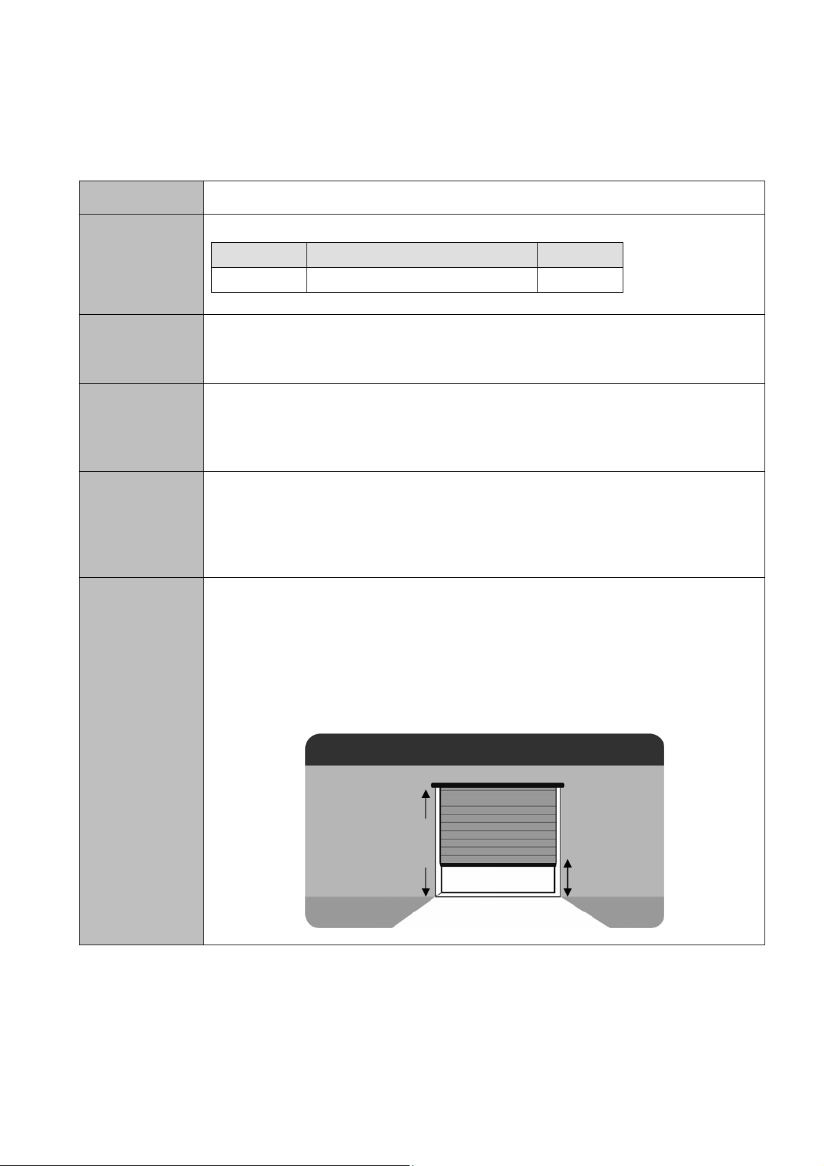
7.5 AC motor internal limit switches and blocking detection function
Model
Associated
parameters
Description
M8,M10,M20,M30
ID Description Type
P1E Limit switch AC motor ON/OFF
P1F Limit opening detected ON/OFF
P20 Limit closing detected ON/OFF
P51 Integrator threshold 1 NUMERIC
P52 Integrator threshold 2 NUMERIC
P3E Max. time/pulses to limit NUMERIC
P54…P5C Switch X SELECTOR
Some VERSUS control panels for AC motors allow detecting motor internal limit
switches and motor blocking status.
The motor blocking status detection is used as a safety function in order to avoid the
motor activation due to a motor malfunction.
Motor internal limit switches detection function allows using the internal limit switches as
an opened/closed position references. The use of these position references ensures a
better door position control.
Configuration
To enable AC motor internal limit switches and blocking detection it is necessary to set
to ON the associated P1E parameter by means of a VERSUS-PROG programming tool.
There is also possible to enable/disable this function by means of assigning this function
to a one of the selector switches (P54 to P5C parameters).
There are also 4 status parameters (read-only parameters) that give information about
this function. The P1F and the P20 parameters are set to ON if dur ing the programmin g
sequence AC motor internal switches are detected (P1F for the opening limit switch and
P20 for the closing limit switch). P51 and P52 parameters inform about the electronic
integrator circuit measured thresholds. These thresholds are measured during the
programming sequence and they take a numeric value. They can be used to check an
installation by an advanced installer or for customer service purposes.
Finally, there is another numeric configuration parameter that is used if AC motor internal
limit switches detection is enabled. This is the P3E parameter and it configures the extra
time/pulses that are added to search the programmed position reference s
29
COD. 1257066 Gamma VERSUS Manual v1.7
Page 30

GAMMA VERSUS MANUAL
Operating
Notes
After enabling these functions, a new programming sequence will be needed. During this
programming sequence, internal limit switches will be searched.
With this function enabled, the programming sequence is slightly different to the normal
programming sequence.
After the first press, the control panel will start opening the door for 2 seconds and
automatically it will close the door in order to search the close internal limit switch. After
detecting it, it automatically starts opening the door until it detects the open internal limit
switch and stops. Then it will start counting the autoclosing time (if not autoprogramming
function is enabled). With another press the door will close until close internal limit switch
is detected again. Finally the control panel will exit the programming sequence mode.
2–ClosestodetectCLOSED
internallimitswitch
3–OpenstodetectOPENEDinternal
limitswitchandcalculateopening
1–Opens2seconds
maneuver
4–ClosestodetectCLOSEDlimit
switchagainandcalculateclosing
maneuver
30
COD. 1257066 Gamma VERSUS Manual v1.7
Page 31

GAMMA VERSUS MANUAL
7.6 Autoclosing function
Model
Associated
parameters
Description
Configuration
Operating
All
ID Description Type
P02 Autoclose ON/OFF
P41 Autoclose value NUMERIC
The autoclose function allows closing automatically the door after a certain period of time
in opened position.
To enable the autoclose function, it is needed to set to ON the P02 configuration
parameter by means of a VERSUS-PROG programming tool. It is also possible to
enable or disable this function by setting the autoclose ON/OFF function to an option
switch.
Autoclosing timeout is configured during the programming sequence but its value can be
checked or modified by using the P41 configuration parameter. This parameter can take
values from 0 seconds to several minutes. The units used for this parameter are
seconds.
If the autoclose function is enabled when the maneuver reaches the opened position it
starts a timer. When the timer value is equal to the autoclose timeout value the control
panel starts closing automatically the door.
Notes
If autoprogramming function is enabled, after the programming sequence, a 30 second
autoclosing timeout default value is set.
There are several cases that the autoclosing timer is cancelled/restarted:
- When “stop” command is received.
- When the number of closing security auto tests retries expires.
- When the number of closing se curity inversions are reached.
- When an “open” command is received (in this case autoclosing timer is
restarted)
31
COD. 1257066 Gamma VERSUS Manual v1.7
Page 32

GAMMA VERSUS MANUAL
7.7 Close by security contact function
Model
Associated
parameters
Description
Configuration
Operating
All
ID Description Type
P1A Closing by SEC.CL ON/OFF
P49 Time to close by SEC.CL NUMERIC
The close by security contact function allows closing automatically the door after security
contact has been activated (when car has already exited/entered).
To enable the close by security contact function it is needed to set to ON the P1A
configuration parameter by means of a VERSUS-PROG programming tool. It is also
possible to enable or disable this function by setting the “Close by SEC.CL ON/OFF”
function to an option switch.
The P49 configuration parameter allows modifying the pause timer that is started after
the door reaches the opened position and the security contact is activated. This
parameter can take values from 0 seconds to several minutes. The units used for this
parameter are seconds.
If the close by security contact function is enabled, when the security contact is activated
during the opening maneuver or when the door is already open, it automatically starts
closing the door from the opened position after the pause timer expires. This allows to
automatically closing the door when a car has already exited or entered to the garage.
Notes
The close by security command is lost in several cases:
- When “stop” command is received.
- When the number of closing security auto tests retries expires.
- When the number of closing se curity inversions are reached.
- When an “open” command is received.
32
COD. 1257066 Gamma VERSUS Manual v1.7
Page 33

GAMMA VERSUS MANUAL
7.8 Deadman function
Model
Associated
parameters
Description
Configuration
All
ID Description Type
P07 Deadman ON/OFF
P4F Press.time to deadman NUMERIC
P5E...P77 IN XX INPUT
The deadman function allows moving the door even securities are activated.
To enable the deadman function it is needed to set to ON the P07 configuration
parameter by means of a VERSUS-PROG programming tool. It is also possible to
enable or disable this function by setting the “Deadman ON/OFF” function to an option
switch.
The P4F configuration parameter allows modifying the button pressing time (button or
deadman transmitter) needed to enter to deadman mode if a security is active.
P5E to P77 parameters allow assigning an input value to every available control panel
input. “Open deadman” and “Close deadman” input values can be assigned to these
inputs. By using these inputs control panel enters directly to deadman mode.
Operating
There are four ways to enter to the deadman mode:
1 - Deadman mode enabled by P07 configuration parameter. Every “open” and “close”
command (even by control panel button or deadman transmitter) will move the door in
deadman without taking into account the security inputs status.
2 - It is possible to enter to deadman mode, in programming state, by pressing the open
and close buttons in order to fix the door position before starting the programming
sequence.
3 – Control panel enters to deadman mode if there is any input configured as “Open
deadman” or “Close deadman” type and it is activated.
33
COD. 1257066 Gamma VERSUS Manual v1.7
Page 34

GAMMA VERSUS MANUAL
Notes
4 - Control panel enters to deadman mode in case of user wants to move the door (by
using an “open” of “close” command) and there is a security activated. It is needed to
press the open or close button (even by using a deadman transmitter) at least the
pressing time defined by the P4F configuration parameter. Meanwhile the open and
close button is pressed the LED associated to the active security will flash in order to
inform the user.
By security, normal transmitters can’t be used to enter to deadman mode. Only special
deadman transmitters can be used.
In deadman mode securities are not taken into account but stop command and
mechanical limit switches signals have higher priority. Therefore is a stop command or a
mechanical limit switch is detected during deadman mode the movement will stop.
7.9 No stop on opening function
Model
All
Associated
parameters
Description
Configuration
Operating
Notes
ID Description Type
P03 No stop on opening ON/OFF
The no stop on opening function avoids stopping the opening maneuver if an
“alternative” or “close” pushbutton is pressed.
To enable the no stop on opening function it is needed to set to ON the P03
configuration parameter by means of a VERSUS-PROG programming tool. It is also
possible to enable or disable this function by setting the “No stop on opening ON/OFF”
function to an option switch.
If this function is enabled when an “alternative” of “close” pushbbutton is pressed during
the opening maneuver it is not taken into account.
This function is normally used on neighboring communities to avoid closing the door if a
neighbor is waiting while the door opens and a new neighbor arrives and presses again
the transmitter.
Even no stop on opening function is enabled, “stop” commands or security commands
are taken into account to ensure user security.
34
COD. 1257066 Gamma VERSUS Manual v1.7
Page 35

GAMMA VERSUS MANUAL
7.10 Radioband function
Model
Associated
parameters
Associated
errors
Description
All
ID Description Type
P28 RBAND mode ON/OFF
P23 RBAND detected ON/OFF
P2E Deadman if RSEC virgin ON/OFF
ID Description Type
Er19 Test closing error Error
Er20 Test opening error Error
Er30 RBAND not found Error
Er31 RBAND not programmed Error
Wr10 Closing security edge active Warning
Wr11 Opening security edge active Warning
The Radioband function allows using the Radioband security system on the VERSUS
control panels.
Configuration
Operating
System set-up: In order to use Radioband system on VERSUS control panels an
RSEC/R receiver must be connected to the control panel on the EXPANSION connector.
Moreover, before proceeding with the control panel programming process it is needed to
program the Radioband transmitter to the RSEC/R receiver (see Radioband transmitter
and RSEC/R receiver user instructions to learn how to perform this programming
process).
Parameters: To enable the Radioband function it is needed to set to ON the P28
configuration parameter by means of a VERSUS-PROG programming tool.
The parameter P23 is a status configuration parameter and it is set to ON when during
the programming maneuver sequence a Radioband system is detected (RSEC/R
receiver is detected and Radioband transmitter has been programmed on the receiver).
After connecting the Radioband system for the first time the control panel detects the
system and displays the Er31 error to inform the user that it is necessary to program the
maneuver in order to store the Radioband configuration.
35
COD. 1257066 Gamma VERSUS Manual v1.7
Page 36

GAMMA VERSUS MANUAL
In the opposite hand, if the maneuver has been already programmed when a
Radioband system was connected and the RSEC/R receiver is not detected, Er30 is
displayed to inform the user that a Radioband system was previously programmed and
now it is not detected. In this case there are two options: RSEC/R is connected again or
control panel maneuver has to be programmed again.
After setting-up the hardware, configured the parameters and programmed the
maneuver sequence, the Radioband system is ready. The programmed Radioband
transmitters will be taken into account during the normal operation as following:
- Every time a maneuver is started the programmed Radioband transmitters are
tested (autotest process is performed). In autotest process, RSEC/R tries to
communicate via radio with the Radioband transmitter. The time needed to
perform an autotest process goes from a few milliseconds to 12 seconds at
maximum (every attempt takes about 3 seconds at maximum and the maximum
number of attempts are 4). After the 12 seconds if no Radioband transmitter
answer is received an autotest error occurs. Er19 error for closing autotest and
Er20 error for opening autotest.
- If during normal operation Radioband security activation is detected, control
panel executes the security inversion maneuver and displays the Wr10 or Wr11
warning in order to inform user that activation has occurred (Wr10 is due to a
closing security edge activation and the Wr11 is due to opening security edge
activation).
Notes
If Radioband system is used in closing maneuver it is also possible to inhibit the
Radioband activation during a portion of the closing maneuver (the last 4cm). By using
this function, it is not necessary to avoid pressing the closing edge during the maneuver
programming sequence. Therefore it is possible to let the door completely closed with
the security edge pressed or activated. To program or configure the Radioband
inhibition zone it is necessary to use the same parameters that are used to define the
inhibition zone for wired security edges (see chapter 7.15).
If the configuration parameter P2E is active and the Radioband Transmitter has not yet
been programmed into the receiver RSEC/R, the control panel will operate only in
deadman mode. Likewise if you unsubscribe the Radioband transmitter to the receiver
RSEC/R, the control panel will operate in deadman mode. It will stop working in this
mode at the moment that another RadioBand transmitter is programmed again into the
receiver RSEC/R.
For more information and details regarding the Radioband system please refer to the
Radioband transmitter and RSEC/R user instructions.
36
COD. 1257066 Gamma VERSUS Manual v1.7
Page 37

GAMMA VERSUS MANUAL
7.11 Radiosens function
Model
Associated
parameters
Associated
errors
All
ID Description Type
P29 RSENS mode ON/OFF
P2A RSENS detected ON/OFF
P92 RSENS dynamic radio ON/OFF
P53 RSENS inhibition margin NUMERIC
ID Description Type
Er19 Test closing error Error
Er22 RSENS not found Error
Er23 RSENS not programmed Error
Er33 RSENS synch. error Error
Er36 RSENS radio error Error
Wr18 RSENS activation Warning
Description
Configuration
The Radiosens function allows using the Radiosens security system on the VERSUS
control panels.
System set-up: In order to use Radiosens system on VERSUS control panels an
RSEC/R receiver must be connected to the control panel on the EXPANSION connector.
Moreover, before proceeding with the control panel programming process it is needed to
program the RSENS transmitter to the RSEC/R receiver (see RSENS transmitter and
RSEC/R receiver user instructions to learn how to perform this programming process).
Parameters: To enable the Radiosens function it is needed to set to ON the P29
configuration parameter by means of a VERSUS-PROG programming tool.
The parameter P2A is a status configuration parameter and it is set to ON when during
the programming maneuver sequence a Radiosens system is detected (RSEC/R
receiver is detected and Radiosens transmitter has been programmed on the receiver).
37
COD. 1257066 Gamma VERSUS Manual v1.7
Page 38

GAMMA VERSUS MANUAL
The P92 parameter is used in order to activate the Radiosens dynamic radio function.
This function allows to dynamically adjusting the RSENS transmitting radio power
according to the radio link quality. If this function is enabled and the radio link quality is
bad the RSENS transmitter battery can reduce its battery life faster.
As the Radiosens system is used as a wireless security system for closing maneuvers
it is also possible to define an inhibition zone for the last centimeters of the maneuver.
The inhibition zone is not compulsory for the Radiosens system as this system detects
the door impact against the ground and the Radiosens sensor memorizes this impact.
Afterwards the impact data will be taken into account during the normal operation.
Even so if user wants to inhibit the last centimeters of the closing maneuver he can do
it by configuring the P53 parameter. This parameter can take values from 0 to 200. The
closing maneuver is divided into 200 sections or portions, and the parameter defines
the number of the portions where the Radiosens system will be not active. For example
if the parameter takes the 10 value this means that the last 10 portions of the closing
maneuver the Radiosens system will be inhibited. If we export this data to a 2-meter
door this means that the last 10 centimeters of the closing maneuver won’t take into
account the Radiosens activation.
Moreover because of the uncontrolled vibrations that are detected when the motor
starts closing the door, by default the Radiosens system is inhibited during the first 10
maneuver portions of the closing maneuver.
Besides being able to set the end zone of inhibition by parameter P53, it is possible to
set it without the VERSUS-PROG programming tool during programming of the
maneuver. If the Radiosens system is used, when the maneuver is
programmed 2 opening-closing sequences are performed. The first sequence
is performed by the user to program the travels of opening and closing. The second
maneuver is carried out automatically so that the Radiosens system performs its
measurements. It is during the closing sequence of the second maneuver when the
user can set the closing inhibition zone for Radiosens system. Using the
alternative button (START) of the control panel the user can specify the starting
point of the inhibition zone during the closure. You can also use a
transmitter configured as an alternative for this indication. If instead, the user takes no
action during this automatically closing sequence, the inhibition zone will be set by
default. The indication of the starting point of the inhibition zone by the alternative
button (START) will only take effect when over 10% of the closing maneuver, in order
to avoid total inhibition of the maneuver.
It is possible to check the inhibition zones by means of the RSENS transmitter. During
the first 25 closing maneuvers, the RSENS transmitter red LED lights when the
Radiosens is inhibited. Therefore the LED is ON during the first 10 maneuver portions
and it is set to ON again when it enters to the last inhibition portions configured by
using the P53 parameter. After the 25 maneuvers are reached the LED doesn’t lights
again unless battery is removed and replaced again.
RADIOSENSfixed
inhibitionmargin(10
steps)
P53RADIOSENS
configurable
inhibitionmargin
Closing
maneuveris
dividedinto200
steps
38
COD. 1257066 Gamma VERSUS Manual v1.7
Page 39

GAMMA VERSUS MANUAL
Operating
After connecting the “RSEC/R receiver + RSENS transmitter“ system for the first time
the control panel detects the system and displays the Er23 error to inform the user that
it is necessary to program the maneuver in order to store the Radiosens configuration.
In case of using the Radiosens system the programming maneuver procedure is
different to the normal procedure. Just after finishing the maneuver programming
sequence, the control panel executes an automatic opening and closing maneuvers in
order to let the Radiosens system perform its measures and calibrations that will be
used during the normal operation. After these extra automatic maneuvers the control
panel exits the programming state.
In the opposite hand, if the maneuver has been already programmed when a
Radiosens system was connected and the RSEC/R receiver is not detected, Er22 is
displayed to inform the user that a Radiosens system was previously programmed and
now it is not detected. In this case there are two options: RSEC/R is connected again or
control panel maneuver has to be programmed again.
In case user modifies any configuration parameter related to the Radiosens system (i.e.
P92 or P53) the Er33 error will be displayed. This error means that some configuration
parameter has changed and it is needed to pass the new parameter values to the
RSENS transmitter. Because of this is necessary to synchronize the RSENS transmitter
to the RSEC/R receiver by programming again the transmitter to the receiver.
After setting-up the hardware, configured the parameters and programmed the
maneuver sequence the Radiosens system is ready. Therefore, the programmed
RSENS transmitter will be taken into account during the normal operation. These are
the operations that are performed during the normal operation:
- Every time a closing maneuver is started the programmed RSENS transmitter is
tested (autotest process is performed). In autotest process RSEC/R tries to
communicate via radio with the RSENS transmitter. The time needed to
perform an autotest process goes from a few milliseconds to 12 seconds at
maximum (every attempt takes about 3 seconds at maximum and the maximum
number of attempts are 4). After the 12 seconds if no RSENS transmitter
answer is received an autotest error occurs. Because is a closing autotest Er19
is displayed.
- If during normal operation Radiosens security activation is detected control
panel executes the opening security inversion maneuver and displays the Wr18
warning in order to inform user that activation has occurred.
During the normal operation or the system installation the Er36 error can be shown. The
main meaning of this error is that the radio link between the RSEC/R receiver and the
RSENS transmitter has been lost. In addition to the shown error, the RSEC/R receiver
will issue 6 beeps.
39
COD. 1257066 Gamma VERSUS Manual v1.7
Page 40

GAMMA VERSUS MANUAL
Notes
There are several reasons that produce this error. The more evident reason is that the
RSENS transmitter batteries are empty and they need to be replaced. But in other
cases this error means radio interfer ences or a weak radio link. In these other cases
the installation must be analyzed and some basic rules must be checked:
- The control panel must not be not far away from the RSENS transmitter (10
meter maximum).
- Metallic parts are not allowed between the control panel and the RSENS
transmitter.
- Some other radio sources (mainly those that are working on the same 868MHz
band) can interfere to the Radiosens radio communication.
Pedestrian mode is not allowed when Radiosens system is used.
Opening inversion maneuvers are not allowed when Radiosens system is used. Every
closing maneuver must start from the OPENED point and it has to be executed the
whole closing maneuver.
Control panel sequence must be programmed again in case of any mechanical
alteration or modification (installation maintenance, knock on the door, etc.). Even
though a mechanical modification or alteration causes non desirable Radiosens
detections and inversions it is possible to close the door by means of Deadman mode.
Model
Associated
parameters
For more information and details regarding the Radiosens system please refer to the
RSENS transmitter and RSEC/R user instructions.
7.12 Electro lock and reverse strike at open functions
All
ID Description Type
P4A Electro lock time NUMERIC
P78...P7C OUT XX OUTPUT
PA1…PB0 (TL-CARD-V) OUT XXX OUTPUT
P27 Maximum speed close ON/OFF
PBD Reverse strike at open ON/OFF
P54…P5C Switch X SELECTOR
Description
The Electro lock function allows controlling an electro lock by means of a control panel
output.
40
COD. 1257066 Gamma VERSUS Manual v1.7
Page 41

GAMMA VERSUS MANUAL
Configuration
To enable the electro lock function it is needed to assign the “Electro lock “output value
to a control panel output. P78 to P7C configuration parameters allow assigning an
output value to every available control panel outputs by means of a VERSUS-PROG
programming tool. PA1 to PB0 configuration parameters allow assigning an output
value to expanded outputs that are available if TL-CARD-V is connected to the control
panel. Electro lock function is enabled if one or more outputs are configured as “Electro
lock” outputs. If electro lock function has to be disabled, “Electro lock” outputs must
change its value.
Electro lock timer is configured by means of the P4A parameter. This parameter can
take values from 0 seconds to several seconds. The units used for this parameter are
seconds.
In control panels models that allow regulation of speed and slow speed, there is the
possibility of activating the closing at maximum speed function by setting P27
configuration parameter. The closing at maximum speed makes a closing operation of
2 seconds after the slow speed part has finished, ensuring proper closure of the
door and that the electrolock closes properly.
Finally, the reverse strike at open function is a function normally associated to the
electrolock function. To enable this function, use the PBD configuration parameter.
There is also possible to control this function by means of assigning this function to one
of the selector switches (P54 to P5C parameters).
Operating
After electro lock function is enabled, the control panel executes the electro lock
sequence every time an opening maneuver is started. The electro lock time is divided
in two parts: the first half time before the opening maneuver and the second half time
once the opening maneuver has started.
(P4AElectrolock
time)/2Electro
active+door
opening
(P4AElectrolocktime)/2Electro
active+doorstopped
The reverse strike at open function is done from the position of door CLOSED. If this
function is activated once the open command has been received, the door will close
during a little period of time to be able to liberate the door and then it will begin the
opening sequence. If at the same time, the electrolock function is activated, this will be
kept active during the liberation time of the door.
Notes
Electro lock can be controlled by means of a free voltage output or a voltage output.
In case of the TL-CARD-V all its four outputs are free voltage but in case of the control
panel outputs it depends on the control panel model. Some control panels have 12Vdc
outputs and other control panel models have 12/24Vdc configurable outputs.
If voltage outputs are used electro lock power consumption has to be carefully taken
into account. Control panel output maximum current depends on the control panel
41
COD. 1257066 Gamma VERSUS Manual v1.7
Page 42

GAMMA VERSUS MANUAL
model. If control panel output maximum current is not enough some control panel
models have an auxiliary input (IN AUX) in order to supply extra current to the voltage
outputs. In this case an extra power supply must be used and connected to this
auxiliary input.
If free voltage output is used an external power supply is needed.
7.13 Backjump function
Model
Associated
parameters
Description
Configuration
All
ID Description Type
P0F Backjump opening enable ON/OFF
P10 Backjump closing enable ON/OFF
P3C Backjump opening time NUMERIC
P3D Backjump closing time NUMERIC
The backjump function allows mechanically release the motor after the control panel
reaches the OPENED and CLOSE maneuver reference points.
To enable the backjump function it is needed to set the P0F configuration parameter to
ON in case of opening backjump or set the P10 configuration parameter to ON in case
of closing backjump by means of a VERSUS-PROG programming tool. .
Backjump opening and closing timers are configured by means of the P3C and P3D
configuration parameters. These parameters can take values from 0 seconds to
several seconds. The units used for this parameter are seconds.
Operating
After backjump function is enabled, the control panel executes the backjump sequence
every time an opening or a closing maneuver finishes on the OPENED or CLOSED
reference points. After the door finishes the opening or closing maneuver, it changes
the movement direction during the configured backjump period in order to release the
motor.
P3CBackjump
openingtime
Closingmaneuver
time
P3DBackjump
closingtime
Opening
maneuvertime
42
COD. 1257066 Gamma VERSUS Manual v1.7
Page 43

GAMMA VERSUS MANUAL
7.14 Security contact autotest function
Model
Associated
parameters
Associated errors
Description
Configuration
All
ID Description Type
P5E...P77 IN XX INPUT
P78...P7C OUT XX OUTPUT
P54...P5C Switch X SWITCH
P48 Autotest max attempt NUMERIC
ID Description Type
Er19 Test closing error Error
Er20 Test opening error Error
The security contact autotest function allows automatically test the connected security
contacts before every opening and closing maneuvers to ensure that they are correctly
working.
System set-up: In order to use security contact autotest function on VERSUS control
panels the security contact must be supplied by control panel voltage output.
Depending on the control panel model this output can be 12Vdc or configurable
12/24Vdc. The security contact output it must be connected to the corresponding
control panel input.
Parameters: The output that supplies the security contact must be configured as a
“Close autotest signal” if the security contact is used for closing maneuvers or “Open
autotest signal” if the security contact is used for opening maneuvers. This
configuration can be done by means of P78 to P7C configuration parameters by using
a VERSUS-PROG programming tool. For the security contact signal input it must be
configured as “SEC.CL autotest” in case of closing maneuver or “SEC.OP autotest” in
case of opening maneuvers. This configuration can be done by means of P5E to P77
configuration parameters.
43
COD. 1257066 Gamma VERSUS Manual v1.7
Page 44

GAMMA VERSUS MANUAL
Operating
When the control panel output and an input are correctly configured to test the
security contact, the autotest sequence is automatically executed. If user wants to
enable or disable the autotest sequence, a switch can be configured as “SEC.CL
test” or “SEC.OP test”. This configuration can be done by means of P54 to P5C
configuration parameters.
If autotest sequence fails, the control panel can try to execute again the autotest
sequence. The number of maximum number of tries can be configured by means of
the P48 configuration parameter. This parameter can take values from 0 to 200.
After security contact autotest function is configured and enabled, the control panel
executes the autotest sequence every time an opening or a closing maneuver starts.
These are the autotest sequence steps:
- In the first step, the control panel removes the power supply of the security
contact by using the configured test output.
- In the second step, the control panel checks that the test input has no signal.
This means that the security contact has released its output.
- In the third step, the power supply of the security contact is recovered.
- Finally in the fourth step it checks that the test input recovers the security
signal.
If any of these steps fail, the autotest sequence is not OK. In case there are autotest
attempts, it repeats again the sequence until the maximum number of attempts are
reached. Finally if the number of maximum number of attempts is reached autotest
error is displayed. In case of opening autotest error Er20 is displayed and in case of
closing autotest error Er19 is displayed.
Notes
Every autotest sequence can take at maximum 4 seconds. Therefore the autotest
maximum period depends on the number of configured attempts.
Even an autotest error happens it is possible to open/close the door by means of
Deadman mode.
44
COD. 1257066 Gamma VERSUS Manual v1.7
Page 45

GAMMA VERSUS MANUAL
7.15 Security edge autotest function
Model
Associated
parameters
Associated errors
Description
All
ID Description Type
P5E...P77 IN XX INPUT
P78...P7C OUT XX OUTPUT
P54...P5C Switch X SWITCH
P48 Autotest max attempt NUMERIC
ID Description Type
Er12 Test edge closing error Error
Er13 Test edge opening error Error
The security edge autotest function allows automatically test the 8K2 wired security
edges that allow autotest (i.e. Radioband external receiver with 8K2 output). The
autotest is performed before every opening and closing maneuvers to ensure that they
are correctly working.
Configuration
System set-up: In order to use security contact autotest function on VERSUS control
panels the wired security edge must be supplied by control panel voltage output.
Depending on the control panel model this output can be 12Vdc or configurable
12/24Vdc. Regarding the wired security edge output it must be connected to a control
panel.
Parameters: The output that supplies the security edge must be configured as a “Close
autotest signal” if the security wired edge is used for closing maneuvers or “Open
autotest signal” if the security wired edge is used for opening maneuvers. This
configuration can be done by means of P78 to P7C configuration parameters by using a
VERSUS-PROG programming tool. In case of security wired edge signal input it must
be configured as “S.EDGE.CL autotest” in case of closing maneuver or “S.EDGE.OP
autotest” in case of opening maneuvers. This configuration can be done by means of
P5E to P77 configuration parameters.
45
COD. 1257066 Gamma VERSUS Manual v1.7
Page 46

GAMMA VERSUS MANUAL
Operating
In case that a control panel output and an input are correctly configured to test the
security wired edge, the autotest sequence is automatically executed. If user wants to
enable or disable the autotest sequence a switch can be configured as “SEC.CL test”
or “SEC.OP test” in order to decide if autotest sequence is executed or not. This
configuration can be done by means of P54 to P5C configuration parameters.
If autotest sequence fails control panel can try to execute again the autotest
sequence. The number of maximum number of tries can be configured by means of
the P48 configuration parameter. This parameter can take values from 0 to 200.
After security wired edge autotest function is configured and enabled, the control
panel executes the autotest sequence every time an opening or a closing maneuver
starts. These are the autotest sequence steps:
- In the first step the control panel removes the power supply of the security
wired edge by using the configured test output.
- In the second step the control panel checks that the test input has no signal.
This means that the security wired edge has released its output.
- In the third step is recovers the power supply of the security wired edge.
- Finally in the fourth step it checks that the test input recovers the security
signal.
If any of these steps fail the autotest sequence is not OK. In case there are autotest
attempts it repeats again the sequence until the maximum number of attempts are
reached. Finally if the number of maximum number of attempts is reached autotest
error is displayed. In case of opening autotest error Er13 is displayed and in case of
closing autotest error Er12 is displayed.
Notes
Every autotest sequence can take at maximum 4 seconds. Therefore the autotest
maximum period depends on the number of configured attempts.
Even an autotest error happens it is possible to open/close the door by means of
Deadman mode.
46
COD. 1257066 Gamma VERSUS Manual v1.7
Page 47

GAMMA VERSUS MANUAL
7.16 Closing security wired edge or Radioband inhibition function
Model
Associated
parameters
Description
Configuration
All
ID Description Type
P06 Inhib. 4cm S.EDGE.CL ON/OFF
P42 Inhib. zone start point NUMERIC
The security edge inhibition function allows inhibit the closing security edge activation
during the last closing maneuver centimeters. This function is common for wired 8K2 or
optical security edges and for Radioband system.
To enable the closing edge inhibition function it is needed to set the P06 configuration
parameter to ON by means of a VERSUS-PROG programming tool.
The inhibition zone is the last centimeters of the closing maneuver and it can be
configured by means of the P43 configuration parameter. This parameter is a position
parameter and the units that are used depend on the time or Hall mode configuration. If
the control panel is working on the time mode seconds are used as units and the
inhibition zone can take values from 0 to 180 seconds. On the other hand, if control
panel is working on the Hall mode pulses are used as units and the inhibition zone can
take values from 0 to 18000 pulses. This inhibition zone value is common for normal
8K2 wired edge, optical wired edge or Radioband controlled edge.
Operating
Notes
P42Inhibi.zone
startpoint
After closing edge inhibition function is configured and enabled, in normal operation
when there is security activation due to an 8K2 closing edge, optical closing edge or
closing Radioband it is not taking into account and the door will continue the closing
maneuver.
VERSUS control panels are ready to directly control WITT (http://www.witt-
sensoric.com/) and FRABA (http://www.fraba.com/) wired optical edges.
47
COD. 1257066 Gamma VERSUS Manual v1.7
Page 48

GAMMA VERSUS MANUAL
7.17 Closing security contact inhibition function
Model
Associated
parameters
Description
Configuration
All
ID Description Type
P08 SEC.CL inhibition ON/OFF
P18 SEC.CL programmed ON/OFF
P3B SEC.CL inhib. point NUMERIC
P42 Inhib. zone start point NUMERIC
The closing security contact function allows inhibit the closing security contact for a
specific zone of the closing maneuver. This function is used in 2-leaf up and over
doors that are installed in such way that the door passes in front of the closing
security contact when it executes the closing maneuver.
To enable the closing security contact inhibition function it is needed to set the P08
configuration parameter to ON by means of a VERSUS-PROG programming tool.
After enabling this function the control panel sequence must be programmed in order
to detect the security contact activation (activated by the door) and this activation
defines the security contact position.
If the security contact is activated during the programming of the closing maneuver
P18 configuration status parameter is set to ON.
The inhibition zone is defined by the sum of the following two parameters:
- The programmed security contact position is defined by the configuration
status parameter P3B. This parameter is stored during programming
sequence if security contact is detected. This is a position parameter and its
units are seconds or pulses depending on the working mode (time or Hall).
- The inhibition margin is defined by the configurable parameter P42. This
parameter is the same that is used in order to define the security edge
inhibition zone. It is a position parameter; therefore its units are seconds or
pulses depending on the working mode (time or Hall). This margin is added to
the previous security contact position to get as result the whole inhibition
zone.
48
COD. 1257066 Gamma VERSUS Manual v1.7
Page 49

GAMMA VERSUS MANUAL
Operating
Notes
Securitycontact
inhibit.zone
After closing security contact inhibition function is configured and enabled, in normal
operation when door is closing when it enters to the security contact inhibition zone any
security contact activation doesn’t produces an inversion maneuver.
Any manipulation or alteration of the closing security contact installation that can modify
its position or presence implies a new control panel programming sequence.
P42Inhib.Zone
point
startpoint
P3BSEC.CLinhib.
7.18 Automatic 8K2/optical security edge detection function
Model
Associated
parameters
Associated errors
All
ID Description Type
P5E...P60 IN X INPUT
P29...P31 Autodetect OptoEdge INX ON/OFF
ID Description Type
Wr10 Security edge closing active Warning
Wr11 Security edge opening active Warning
Wr37 S. Optical edge opening active Warning
Wr38 S.Optical edge closing active Warning
Description
The security edge autotest function allows automatically test the 8K2 wired security
edges (i.e. Radioband external receiver with 8K2 output). The autotest is performed
before every opening and closing maneuvers to ensure that they are correctly working.
49
COD. 1257066 Gamma VERSUS Manual v1.7
Page 50

Configuration
GAMMA VERSUS MANUAL
System set-up: VERSUS control panels have 3 available inputs (IN1 to IN3) that can
automatically detect 8K2 or optical edge signal. Before configuring the parameters the
selected edge has to be connected to the control panel. In case of an 8K2 edge it can
be directly connected but in case of optical edge power supply has to be provided.
Depending on the control panel 12Vdc or 12/24Vdc outputs are available. Usually a
fixed voltage output is used to supply the optical edge. It is also possible to set a
configurable output as fixed output by setting its value to “Always ON”.
VERSUS control panels are ready to directly control WITT (http://www.witt-
sensoric.com/) and FRABA (http://www.fraba.com/) wired optical edges. Please follow
manufacturer datasheet in order to connect the optical edge to the VERSUS control
panel.
Operating
Notes
Parameters: To configure the 3 available inputs as automatic 8K2/optical inputs
“AUTOEDGE.CL” or “AUTOEDGE.OP” input values have to be set depending if the
edge has to actuate during the opening or the closing maneuver. This configuration is
done by using P5E to P60 configuration parameters by means of a VERSUS-PROG
programming tool.
After the edge is connected and the input is configured the 8K2 or optical mode
detection is performed during the normal control panel programming sequence. After
programming, this sequence detection result can be checked by using the P29 to P31
status parameters. If the associated input parameter is set to ON it means that an
optical edge has been detected otherwise a 8K2 edge is taken into account.
After 8K2/optical security edge automatic input function is configured in normal
operation it takes into account its activation. When the edge is activated, the control
panes executes the security inversion maneuver. If the active edge is the closing edge
Wr10 or Wr38 warnings are displayed (8K2 or optical edge) and in this case the
inversion maneuver opens the whole door. If the active edge is the opening edge Wr11
or Wr37 warnings are displayed (8K2 or optical edge) and in this case the inversion
maneuver closes during 2 seconds.
Any change of the 8K2/optical edge mode (from optical to 8K2 or vice versa) implies a
new control panel programming sequence in order to detect the new edge mode.
Even the edge is active it is possible to open/close the door by means of Deadman
mode.
50
COD. 1257066 Gamma VERSUS Manual v1.7
Page 51

GAMMA VERSUS MANUAL
7.19 Flash and pre-flash function
Model
Associated
parameters
Description
Configuration
All
ID Description Type
P91 Pre-Flash option ON/OFF
P78...P7C OUT XX OUTPUT
PA1…PB0 (TL-CARD-V) OUT XXX OUTPUT
P54...P5C Switch X SWITCH
P4C Flash frequency NUMERIC
P4D Pre-Flash time NUMERIC
The flash and pre-flash function allows controlling a warning light.
To enable the flash it is needed to configure any output to “Flash” value. P78 to P7C
configuration parameters allow to assign the “Flash” output to any available control
panel output by means of a VERSUS-PROG programming tool. In addition any TLCARD-V output can be also programmed as “Flash” output by means of PA1 to PB0
configuration parameters.
Operating
Notes
The flashing frequency can be configured by using the P4C configuration parameter.
This flashing frequency can take values from 0.1 to 5 seconds.
Regarding pre-flash function if it has to be enabled P91 configuration parameter has to
be set to ON. If pre-flash function needs to be controlled by user without VERSUSPROG programming tools “Pre-flash ON/OFF” function can be assigned to any switch.
To configure the switch values P54 to P5C configuration parameters can be used.
Pre-flash time value can be configured by using the P4D configuration parameter. This
parameter can take values from 0 to 60 seconds.
After pre-flash/flash function is configured in normal operation it takes into account its
control. If pre-flash is enabled it executes flash during the configured time before start
an opening/closing sequence. After the door starts moving it keep flashing until the
door stops.
In VERSUS control panels, flash function can be assigned to any type of output: free
voltage output, voltage output, TL-CARD-V output and front light output.
51
COD. 1257066 Gamma VERSUS Manual v1.7
Page 52

GAMMA VERSUS MANUAL
7.20 Anti-intrusive function
Model
Associated
parameters
Description
Configuration
All
ID Description Type
P78…P90 OUT XX OUTPUT
PA1…PB0 (TL-CARD-V) OUT XXX OUTPUT
The anti-intrusive function allows detecting a non-desired entrance to the garage (thief,
etc.). This function uses the closing security contact as a sensor to detect this nondesired entrance.
To enable the anti-intrusive function it is needed to configure any of the available
outputs as “Intrusive” by means a VERSUS-PROG programming tool. The P78 to P90
configuration parameters are used to configure the control panel outputs and the PA1
to PB0 configuration parameter are used to configure the TL-CARD-V extra outputs.
The configured “Intrusive” outputs will be activated in case of non-desired entrance
detection. Therefore these outputs can be used to activate any kind of alarm system.
The output is “normally opened” and it changes to “normally closed” when it is
activated. It keeps active until the door is completely closed.
To use the anti-intrusive function, a closing security contact input is compulsory as the
closing security contact is used as presence sensor. Therefore it is needed to configure
any of the available inputs as closing security contact input.
Operating
If any output is configured as “Intrusive” the control panel checks the closing security
contact activations.
If an opening maneuver starts in order to open the garage door, the control panel
checks the number of closing security contact activations.
The first activation is understood as the user enters to its garage but the second
activation means a non-desired entrance. If this second activation is detected before
the door returns to the CLOSED status “Intrusive” outputs are activated in order to
inform about a non-desired entrance.
52
COD. 1257066 Gamma VERSUS Manual v1.7
Page 53

GAMMA VERSUS MANUAL
7.21 Alarm function
Model
Associated
parameters
Description
Configuration
All
ID Description Type
P78…P90 OUT XX OUTPUT
PA1…PB0 (TL-CARD-V) OUT XXX OUTPUT
P0A Closing limit switch installed ON/OFF
The alarm function allows detecting a non-desired opening maneuver of the garage
door (thief, etc.). This function uses the closing mechanical limit switch as a sensor to
detect this non-desired opening maneuver.
To enable the alarm function it is needed to configure any of the available outputs as
“Alarm” by means a VERSUS-PROG programming tool. The P78 to P90 configuration
parameters are used to configure the control panel outputs and the PA1 to PB0
configuration parameter are used to configure the TL-CARD-V extra outputs.
The configured “Alarm” outputs will be activated in case of non-desired opening
maneuver. Therefore these outputs can be used to activate any kind of alarm system.
The output is “normally opened” and it changes to “normally closed” when it is
activated. It keeps active until the alarm condition is resolved.
Operating
To use the alarm function a closing mechanical limit switch input is compulsory as the
mechanical limit switch is used as security sensor. Therefore it is needed to configure
any of the available inputs as mechanical limit switch input.
In order to use the closing mechanical limit switch, it has to be detected on the control
panel programming sequence. After programming the sequence it is possible to check
the detection result by using the status configuration parameter P0A. If this parameter
is set to ON it means that the closing limit switch has been detected.
If any output is configured as “Alarm” and a closing mechanical limit switch has been
detected in programming sequence, the control panel checks the closing mechanical
limit switch when the door is on the CLOSED position.
If manual or forced openings maneuver starts (motor is not activated by the control
panel) the closing mechanical limit switch will be released. In this case as the control
panel is still on the CLOSED position it detects the closing mechanical limit switch
release and it activates the “Alarm” outputs to inform about a non-desired maneuver.
53
COD. 1257066 Gamma VERSUS Manual v1.7
Page 54

GAMMA VERSUS MANUAL
7.22 Panic function
Model
Associated
parameters
Description
Configuration
All
ID Description Type
P78…P90 OUT XX OUTPUT
PA1…PB0 (TL-CARD-V) OUT XXX OUTPUT
P50 Panic active signal NUMERIC
The panic function allows activating a special output by pressing during several
seconds a transmitter button. This transmitter has to be programmed on any of the 4
available Motion channels of the control panel integrated receiver.
This can be used to inform a dangerous or emergency situation by means of a
transmitter (thief, medical emergency, etc.)
To enable the panic function it is needed to configure any of the available outputs as
“Panic” by means a VERSUS-PROG programming tool. The P78 to P90 configuration
parameters are used to configure the control panel outputs and the PA1 to PB0
configuration parameter are used to configure the TL-CARD-V extra outputs.
The configured “Panic” outputs will be activated (pulse output) in case of transmitter
long activation is detected. Therefore these outputs can be used to activate any kind of
alarm system. The output is “normally opened” and it changes to “normally closed”
when it is activated. It keeps active for a short period of time (pulse).
Operating
Notes
To configure the time that is needed to press the transmitter button to activate the
panic signal, P50 parameter can be used. This parameter can take values from 0 to 20
seconds.
If any output is configured as “Panic” and a transmitter is programmed on any of the 4
available Motion channels, the control panel checks the holding time of the transmitter
button.
If this time is larger than the configured time it activates the “Panic” outputs to inform
about a dangerous situation.
As this function uses the transmitter button holding time to activate an emergency
output, radio interferences have to be taken into account, because they can affect to
the “transmitter – control panel” communication.
54
COD. 1257066 Gamma VERSUS Manual v1.7
Page 55

GAMMA VERSUS MANUAL
7.23 Hydraulic mode function
Model
Associated
parameters
Associated errors
Description
All
ID Description Type
P5E...P60 IN X INPUT
P1F Limit opening detected ON/OFF
P20 Limit closing detected ON/OFF
P54...P5C Switch X SWITCH
P42 Inhib. zone start point NUMERIC
P2D Extratime hydraulic mode NUMERIC
ID Description Type
Er19 Test closing error Error
Er20 Test opening error Error
Wr40 Pressure switch active Warning
The hydraulic mode function allows controlling a hydraulic motor that has a pressure
switch output signal.
Configuration
To enable the hydraulic mode function it is needed to configure any of the available
inputs as “Pressure switch” by means a VERSUS-PROG programming tool. The P5E
to P60 configuration parameters are used to configure the control panel inputs.
There are two cases where the pressure switch is activated: when there is any kind of
obstacle that doesn’t allow the motor movement and when the motor starts moving.
- The first case is very useful in order to use the pressure switch as a security
signal and also to use it to detect OPEN and CLOSE references during
programming sequence process. When control panel maneuvers are
programmed, if user reaches the top and bottom door limits and the hydraulic
motor presses for an extratime, that is configured by P2D parameter, in these
points, OPEN and CLOSE references are detected. Therefore in normal
operation these references will be taken into account. To check if these
references have been detected P1F and P20 status configuration parameters
can be used. The ON value means that the reference has been detected.
- The second case is very useful in order to test pressure switch signal. If a
pressure switch signal pulse is detected every time that the motor starts
moving, this signal can be checked to perform the pressure switch autotest. In
order to define the zone where this activation is possible and to inhibit the
pressure switch security signal P42 parameter is used. Therefore every time a
maneuver starts during the time configured by P42 pressure switch is inhibited
and if test is enabled it checks that it is active during a short period of time. To
enable or disable the pressure switch test it is necessary to assign the
“Pressure switch test ON/OFF” function on any of the switches. This
configuration can be done by using the P54 to P5C configuration parameters.
If none switch is configured autotest is enabled by default.
55
COD. 1257066 Gamma VERSUS Manual v1.7
Page 56

Operating
d
GAMMA VERSUS MANUAL
If any input is configured as “Pressure switch”, the control panel is working on
hydraulic mode. In this mode is always using Time mode by default. Hall mode is not
allowed in hydraulic mode.
In normal operation, the pressure switch signal is used as security signal if it is not
inhibited. The signal is inhibited the first seconds of the maneuver. This time is the
configured inhibition time and during this time if the pressure switch test is enabled it
checks its activation. In order to inform the user that the pressure switch signal is
inhibited the STOP/ERROR control panel red LED flashes. After leaving this inhibition
zone the pressure switch is used as a security signal and if there is any activation
control panel executes the security inversion maneuvers. It is possible to inhibit
the pressure signal during the entire opening operation by assigning this function to
a selector with parameters P54 to P5C.
In addition if any reference has been programmed by using the pressure switch signal
(OPENED or CLOSED), the security signal is also inhibited 2 seconds before reaching
the reference point detection. In this case the STOP/ERROR control panel red LED it
also flashes to inform the user that it is inhibited in order to detect the OPENED or
CLOSED reference. Once reached the reference and to ensure proper closing or
opening of the door, the door continue closing / opening for the extra
time parameter set by P2D.
Notes
2sec.inhibition
reference
P42Inhib.Zone
startpoint
If pressure switch test is enabled and there is no signal activation during the inhibition
zone, test fails and Er19 error is displayed in case of closing maneuver test and Er20
error is displayed in case of opening maneuver test.
During normal operation any pressure switch activation that results into a security
maneuver, displays the Wr40 warning in order to inform the user that a pressure switch
security signal has been detected.
Slow speed mode is not allowed if hydraulic motors are used.
If due to maintenance it is necessary to repair the hydraulic motor it is possible to
temporally replace it by a electromechanical motor. In this case pressure switch test
has to be disabled if it is enabled and the pressure switch input can be replaced by a
normally closed contact (bridge).
P20Limitclosingdetecte
P1FLimitopening
detected
2sec.inhibition
reference
If hydraulic motor is used and door is in OPENED or CLOSED position for a long period
of time it is highly recommended to enable the “Recharge maneuver” function in order
to keep the door correctly opened or closed (see 0).
56
COD. 1257066 Gamma VERSUS Manual v1.7
Page 57

GAMMA VERSUS MANUAL
7.24 Recharge maneuver function
Model
Associated
parameters
Description
Configuration
Operating
All
ID Description Type
PB6 Recharge maneuver ON/OFF
The recharge maneuver function allows refreshing the CLOSED and OPENED position
and ensures that the door is correctly opened and closed.
To enable the recharge maneuver function it is needed to set to ON the PB6
configuration parameter by means a VERSUS-PROG programming tool.
If recharge maneuver is enabled the control panel starts a 1 hour timer every time the
door enters to CLOSED or OPENED position. After this timer finishes the control panel
executes a 3 seconds opening maneuver in case of OPENED position or a 3 seconds
closing maneuver in case of CLOSED pos ition. This maneuver is executed in order to
correctly keep the door closed or opened. After these 3 seconds maneuver the control
panel starts again a 1 hour timer in order to refresh again the position after this timer
expires.
If a normal opening or closing maneuver is executed the 1 hour timer is interrupted and
it won’t be started again until the door enters to CLOSED or OPENED position.
57
COD. 1257066 Gamma VERSUS Manual v1.7
Page 58

GAMMA VERSUS MANUAL
7.25 Password blocking function
Model
Associated
parameters
Description
Configuration
Operating
All
ID Description Type
PB1 Block ON/OFF by password ON/OFF
PB4 Current blockage status ON/OFF
PB2 Password value NUMERIC
The password blocking function allows protecting control panel configuration by means
of a password.
To enable the password blocking function it is needed to set to ON the PB1
configuration parameter by means a VERSUS-PROG programming tool.
The password value is set using the PB2 configuration parameter that can take values
from 0000 to 9999 (0000 value is set as default).
The status configuration parameter PB4 allows seeing if the control panel is currently
blocked.
If password blocking function is enabled, configured password value is requested if
user wants to modify control panel configuration. The password value is requested by
VERSUS-PROG programming tools when user tries to modify configuration
parameters.
Notes
If password is correctly introduced control panel is unblocked and user can change its
configuration. After 2 minutes of no user activity control panel is blocked and password
needs to be entered again if configuration needs to be changed.
Option switches changes are not taken into account if control panel is blocked by
password. To take into account switches values password must be introduced by
means of any VERSUS-PROG programming tool.
There is no way to recover or reset the password value, therefore password value lose
implies a control panel repairing process.
For more information and details regarding the password introduction process please
refer to the VERSUS-PROG programming tools user instructions.
58
COD. 1257066 Gamma VERSUS Manual v1.7
Page 59

GAMMA VERSUS MANUAL
7.26 Traffic control function
Model
Associated
parameters
Description
Configuration
All
ID Description Type
P5E…P60 IN X INPUT
P78…P90 OUT XX OUTPUT
PA1…PB0 (TL-CARD-V) OUT XXX OUTPUT
PB2 Traffic control mode NUMERIC
The traffic control function allows managing the entry and exit of vehicles
to neighboring communities where there is a single gateway. The control is
done through 2 traffic lights with red and green traffic lights being installed one on the
outside and one on the inside of the building.
To enable this function, it is not necessary to activate any parameter. Just need to
configure 4 outputs to control the 4 traffic lights (green inside, red inside, red outside
and green outside). If you want to control the traffic lights by the direct outputs of
the control panel, the configuration is required by P78 to P90 parameters. If instead you
want to control the lights via a TL-CARD-V, the configuration is required by the
parameters PA1 to PB0.
Operating
To perform a traffic control is necessary to set up inputs like "Start", "Open",
"Open inside", "Start pedestrian" or "Open pedestrian." To perform this, the
configuration parameters P5E to P60 are used.
By PB2 configuration parameter can be chosen the traffic control mode. Depending on
how the mode is configured, the traffic lights are activated or deactivated in certain
states of the door in a different way.
- JCM traffic control mode (value 0): In this mode, all traffic lights remain off when the
door is closed. During the opening operation red lights come on inside and
outside. Once the door is open the green light is lit inside or outside depending on
whether the opening is performed from inside or outside the building. In this mode radio
commands are interpreted as "Start", "Open", "Open pedestrian" and
"Start pedestrian" as activation commands outside. So if you receive one of these
commands when the door is open, the green outside light comes on and the red inside
light remains on. On the contrary in this way wiring switch commands like "Start",
"Open", "Open pedestrian" and "Start pedestrian" are considered as activation
commands inside. If you receive such a command once the door is open, the green
light is lit inside and red outside light remains on. If it is necessary within a
command by radio can be configured as an input radio channel type "Open inside."
59
COD. 1257066 Gamma VERSUS Manual v1.7
Page 60

GAMMA VERSUS MANUAL
7.27 Error and warning display function
Model
Associated
parameters
Description
Configuration
Operating
All
ID Description Type
P24 Error info displayed ON/OFF
P80 Panel last error NUMERIC
P9A Panel last problem NUMERIC
P9B Panel last warning NUMERIC
The error and warning display function allows expanding the displayed error
information.
To enable the error and warning display function it is needed to set to ON the P24
configuration parameter by means a VERSUS-PROG programmi ng tool.
Last main active error can be checked by means of the P80 status configuration
parameter. Last normal active error or problem can be checked by means of the P9A
status configuration parameter. Finally, last active warning can be checked by means of
the P9B status configuration parameter.
By default control panel reports a limited list of errors. These errors are those that are
critical or those that inform about a security malfunction.
Notes
If user wants to expand the error information in order to see normal errors or warnings,
error and warning function has to be enabled.
If no VERSUS-PROG programming tool is used the only way to know that there is an
active error or warning is taking a look to the control panel STOP/ERROR red LED. If
the LED is ON it means that there is an active error or warning. If error and warning
display function is disabled only critical errors will be informed.
To know the active error or warning value it is necessary to use a VERSUS-PROG
programming tool.
Active errors and warnings keep active until the error is solved and an opening or
closing maneuver is started. Afterwards if everything is ok the error is deactivated
60
COD. 1257066 Gamma VERSUS Manual v1.7
Page 61

GAMMA VERSUS MANUAL
7.28 Opening function with presence detection
Model
Associated
parameters
Description
Configuration
Operating
All
ID Description Type
P54…P5C Switch X SWITCH
The opening function with presence detection allows opening the door only if the user
is near her. The closing security contact input is used as presence detector, so the
opening is not allowed until this input is active (for example you can use
a magnetic loop vehicle detection connected to this input).
To enable this function it is needed to assign the activation to one of the switches by
means of the P54…P5C configuration parameters. Once the function assigned to the
switch, it can be activated setting at ON the switch.
If the function is enabled, if you receive an order to open when the door is closed, the
door will not open if the closing security contact input is not
active (detects presence). After opening the door, the closing security contact will no
longer be used as a presence detector and it will be used as a safety element
during the closing.
Notes
61
COD. 1257066 Gamma VERSUS Manual v1.7
Page 62

GAMMA VERSUS MANUAL
7.29 Bollard control mode function
Model
Associated
parameters
Description
Configuration
All
ID Description Type
P78…P7C OUT XX OUTPUT
PA1…PB0 (TL-CARD-V) OUT XXX OUTPUT
The bollard control mode function allows controlling the maneuver of a bollard and its
signaling lights (crown bollard light, red traffic light and warning traffic light) by the
outputs of the control panel + TL-CARD-V. The bollard to control must have a
certain feature to perform this task: the use of limit switches with pressure
switch and the control of lowering the bollard by disabling 24Vdc solenoid.
To enable this feature, you must assign the bollards control function to one of the
outputs of the control panel. This assignment is done through the configuration
parameters P78 ... P7C. The function of the output configured as bollard control is used
to control the 24VDC solenoid control board of the bollard.
In addition to the own control of the bollard, this mode includes its signaling light
control (crown bollard light, red traffic light and warning traffic light). To perform this
control, it is necessary to assign these light outputs to the outputs of the control panel
or TL-CARD-V through the configuration parameters P78…P7C (control panel)
or PA1…PB0 (TL-CARD-V).
Operating
If the control bollard function is activated in both programming mode and normal
operating, the following actions are performed:
• The output configured as control bollard (value 34) is used to control the activation
board of the 24 VDC solenoid.The solenoids are always active except during the
maneuvers lowering the bollards (maneuver of upping the door).
• The fact that the bollards operate with pressure switches (NC) as limit switches
implies that the control panel inhibits the detection of the switch during the first two
seconds of maneuver.The NO inhibition of these implies false limit switch detecti on or
the interpretation of an STOP (activation at the same time of the 2 limit switches).The
LED STOP/ERROR indicates the activation zone by flashing.
• The fact that the bollards operate with pressure switches (NC) as limit switches also
means that the control panel sets a margin of detection of the switch, if it has been
detected during programming.This margin is about 0.5 seconds before the detection of
the switch and from this point any activation of the switch is interpreted as a reference
for opening/closing.The LED STOP/ERROR indicates this margin of detection of the
switch at the end of the maneuver by flashing.
• The limit switch input of rising bollard (closing door) is also used as a safety signal.In
the area where the limit of rising bollard is not inhibited (first 2 seconds of maneuver
and final margin of detection. LED STOP/ERROR off) and if the limit switch is activated,
it is interpreted as a safetysignal and the bollard reverses its maneuver until down
62
COD. 1257066 Gamma VERSUS Manual v1.7
Page 63

GAMMA VERSUS MANUAL
completely (full opening door).
• If during normal operation, the system loses power supply, it will always start in
"bollard down" mode (door open).In this mode, once finished the closing time, the
bollard will begin its ascent maneuver.
• In order to avoid the lowering of the bollard by pressure loss, the system will perform a
recharge maneuver of 3 seconds each hour.The one-hour period begins at the end of
each recharge and once completed an ascent maneuver (see function 7.24)
• The output set as light crown bollard (value 35) is active when the bollard is fully
raised (door fully lowered) and it will perform flashes during the movement of the
bollard.
• The output set as red traffic light of bollard (value 36) is always active except when
the bollard is fully lowered to disallow the passage.
• The output set as warning traffic light of bollard (value 37) will flash only when the
bollard is fully lowered to indicate passage.
Notes
63
COD. 1257066 Gamma VERSUS Manual v1.7
Page 64

GAMMA VERSUS MANUAL
7.30 Maintenance warning function
Model
Associated
parameters
Description
Configuration
Operating
All
ID Description Typo
P78...P7C OUT XX OUTPUT
PA1…PB0 (TL-CARD-V) OUT XXX OUTPUT
P32 Max.movements number NUMERIC
The maintenance warning function allows the installer to control the maintenance of the
installation. The maintenance warning is activated once it exceeds the maximum number
of maneuvers scheduled.
To enable this function, you must assign the role of maintenance warning to one of the
outputs of the control panel. This assignment is done by configuration parameters P78 ...
P7C if using a control panel output or by output configuration parameters PA1 ... PB0
when using a TL-CARD-V output.
The maximum number of operations is fixed by setting numerical parameter P32.
If the maintenance warning function is activated the control panel does the following:
Notes
• After reaching the maximum number of maneuvers, the output configured as
performed maintenance warning flashes when the door is in the OPEN and
CLOSED positions.
• During the movement of the door, the output configured as maintenance warning
is always off.
64
COD. 1257066 Gamma VERSUS Manual v1.7
Page 65

GAMMA VERSUS MANUAL
8. PROGRAMMING OF MANEUVERS
8.1 Door positioning
Before performing a program the door should be fully in closed position.
8.2 Door positioning in Dead man mode
Press the PROG button to enter Programming mode. The PROG Led will turn on. Through the buttons
OPEN and CLOSE, if there are available, you can position the door to the totally closed position.
65
COD. 1257066 Gamma VERSUS Manual v1.7
Page 66

GAMMA VERSUS MANUAL
8.3 Auto-Programming
Follow the steps to perform the auto-programming. It is necessary to have the autoprogramming function
activated (P01 parameter):
1. Door is in the totally closed position
2. Press PROG pushbutton to enter programming mode
3. The PROG Led will turn on
4. Press START pushbutton or a programmed transmitter to program the maneuver
5. The door opens
6. Press START pushbutton to stop the door at the desired positon
7. The door stops
8. The door closes automatically
9. Press START pushbutton to stop the door at the desired positon
10. The door stops
11. The PROG Led turns off
12. The programming is finished
The control panel is programmed with the following fixed parameters: slow speed manoeuvre is 15% of the
total manoeuvre, the pedestrian opening is 1/3 of the total opening time and autoclosing time is 30 seconds
(in total opening and in partial opening).
66
COD. 1257066 Gamma VERSUS Manual v1.7
Page 67

GAMMA VERSUS MANUAL
8.4 Auto-Programming with internal limit switches detection
Follow the steps to perform the auto-programming with internal limit switches detection. It is necessary to
have the autoprogramming function activated (P01 parameter) and the internal limit switches detection
activated (P1E parameter):
1. Door is in the totally closed position
2. Press PROG pushbutton to enter programming mode
3. The PROG Led will turn on
4. Press START pushbutton or a programmed transmitter to program the maneuver
5. The door opens two seconds and stops
6. The door closes automatically until the closed position
7. The door stops
8. The door opens automatically until a mechanical stop or a limit switch is reached
9. The door stops
10. The door closes automatically until a mechanical stop or a limit switch is reached
11. The door stops
12. The PROG Led turns off
13. The programming is finished
The control panel is programmed with the following fixed parameters: the pedestrian opening is 1/3 of the
total opening time and autoclosing time is 30 seconds (in total opening and in partial opening).
67
COD. 1257066 Gamma VERSUS Manual v1.7
Page 68

GAMMA VERSUS MANUAL
8.5 Manual Programming
Follow the steps to perform the manual programming:
1. Door is in the totally closed position
2. Press PROG pushbutton to enter programming mode
3. The PROG Led will turn on
4. Press START pushbutton or a programmed transmitter to program the maneuver
5. The door opens
6. Press START pushbutton to stop the door at the desired position
7. The door stops
8. Wait to program the desired autoclose time
9. Press START pushbutton to close the door
10. The door closes
11. Press START pushbutton to stop the door at the desired position
12. The door stops
13. The PROG Led turns off
14. The programming is finished
68
COD. 1257066 Gamma VERSUS Manual v1.7
Page 69

GAMMA VERSUS MANUAL
8.6 Manual Programming with internal limit switches detection
Follow the steps to perform the manual programming with internal limit switches detection. It is necessary
to have the internal limit switches detection activated (P1E parameter):
1. Door is in the totally closed position
2. Press PROG pushbutton to enter programming mode
3. The PROG Led will turn on
4. Press START pushbutton or a programmed transmitter to program the maneuver
5. The door opens two seconds and stops
6. The door closes automatically until the closed position
7. The door stops
8. The door opens automatically until a mechanical stop or a limit switch is reached
9. The door stops
10. Wait to program the desired autoclose time
11. Press START pushbutton to close the door
12. The door closes until a mechanical stop or a limit switch is reached
13. The door stops
14. The PROG Led turns off
15. The programming is finished
69
COD. 1257066 Gamma VERSUS Manual v1.7
Page 70

GAMMA VERSUS MANUAL
8.7 Manual Programming with slow speed function activated
Follow the steps to perform the manual programming with slow speed function activated. It is necessary to
have the slow speed function activated (P04 parameter):
1. Door is in the totally closed position
2. Press PROG pushbutton to enter programming mode
3. The PROG Led will turn on
4. Press START pushbutton or a programmed transmitter to program the maneuver
5. The door opens
6. Press START pushbutton at the desired position to move the door at slow speed
7. The door finishes opening at slow speed
8. Press START pushbutton to stop the door at the desired position
9. The door stops
10. Wait to program the desired autoclose time
11. Press START pushbutton to close the door
12. The door closes
13. Press START pushbutton at the desired position to move the door at slow speed
14. The door finishes closing at slow speed
15. Press START pushbutton to stop the door at the desired position
16. The door stops
17. The PROG Led turns off
18. The programming is finished
70
COD. 1257066 Gamma VERSUS Manual v1.7
Page 71

GAMMA VERSUS MANUAL
71
COD. 1257066 Gamma VERSUS Manual v1.7
Page 72

GAMMA VERSUS MANUAL
8.8 Pedestrian Programming
Follow the steps to perform the pedestrian programming:
1. Door is in the totally closed position
2. Press PROG pushbutton to enter programming mode
3. The PROG Led will turn on
4. Press PEDESTRIAN button instead of START pushbutton to program the maneuver
5. The door opens
6. Press PEDESTRIAN button to stop the door at the desired positon
7. The door stops
8. Wait to program the desired autoclose time
9. Press PEDESTRIAN button to close the door
10. The door closes
11. Press PEDESTRIAN button to stop the door at the desired positon
12. The door stops
13. The PROG Led turns off
14. The programming is finished
72
COD. 1257066 Gamma VERSUS Manual v1.7
Page 73

GAMMA VERSUS MANUAL
9. PROGRAMMING CODES IN THE RECEIVER
9.1 Manual Programming MOTION transmitters
Press the receiver programming button for 1 sec. and an acoustic signal will be heard. The receiver will
enter programming mode 1. If the receiver programming button is held pressed down, the receiver will
enter programming modes 2, 3, 4 and 5, cyclically passing from one configuration to the next. Once the
programming configuration for the transmitter to be registered has been chosen, send the code to be
programmed by pressing the transmitter.
Mode Configurationoftransmitterprogramminginthereceiver Led
1 Bypressingthedesiredchannelofthetransmitter,thealternative
inputwillbeactivated
2 Bypressingthedesiredchannelofthetransmitter,thepedestrian
inputwillbeactivated
3 Bypressingthedesiredchannelofthetransmitter,theopeninput
willbeactivated
4 Bypressingthedesiredchannelofthetransmitter,thecloseinput
willbeactivated
5 Programmingofthe4pushbuttonssequentiallyonthereceiver
(alternative,pedestrian,openandclose)
C1
C2
C3
C4
All
intermittent
Every time a transmitter is programmed, the equipment will issue an acoustic signal for 0.5 sec. After 10
seconds without programming or by pressing the programming button, or by pressing the first two buttons
of a transmitter (depending on the programming mode), the equipment will exit programming mode, issuing
two 1 sec. acoustic signals. If, on programming a transmitter, the equipment memory is full, it will issue
seven 0.5 sec. acoustic signals and exit programming.
N.B.: Each transmitter channel can be configured independently on the equipment, occupying only one
memory position.
73
COD. 1257066 Gamma VERSUS Manual v1.7
Page 74

GAMMA VERSUS MANUAL
9.2 Programming by radio
To enter programming, press the first two buttons on a transmitter that has already been registered on the
equipment. The equipment will issue a 1 sec. acoustic signal. On pressing any button on the new
transmitter, the equipment will issue another 1 sec. acoustic signal to indicate that it has been memorised.
The new transmitter will maintain the same channel configuration as the transmitter registered.
After 10 seconds without programming or by quickly pressing the programming button or pressing the first
two transmitter buttons, the equipment will exit programming mode, issuing two 1 sec. acoustic signals.
9.3 Reset
In programming mode, the programming button is held down for over 10 sec. The equipment will issue 10
short acoustic warning signals followed by others at a faster pace to indicate that the operation has been
successful. The equipment is now in programming mode. The pilot programming light will also follow the
acoustic indications by flashing.
After 10 seconds without programming or quickly pressing the programming button, the equipment will exit
programming mode, issuing two 1 sec. acoustic signals.
74
COD. 1257066 Gamma VERSUS Manual v1.7
Page 75

GAMMA VERSUS MANUAL
10. ACCESSORIES
10.1 VERSUS-PROG portable programmer
BACKLIT DISPLAY
ACTION CANCELLATION KEY
HORIZONTAL MENU
VERTICAL MENU
COMMUNICATION CABLES
CONNECTION
HOT KEYS
ON/OFF KEY
BATTERIES
ACTION VALIDATION KEY
1. DESCRIPTION
This is a portable tool that permits to parameterize certain specifications (Inputs, outputs and software functions)
from new generation control panels. Is also compatible with panels which are programmable with PROG-MAN.
It operates via a rotary menu using fixed and configurahble function keys
It has a backlit display, which shuts down after 20 seconds of inactivity. The programmer has an automatic cut-off
function after 3 minutes to save battery.
Configuration cables for the new generation control panels are supplied VERSUS.
2. TECHNICAL SPECIFICATIONS
Frequency 868,35MHz / 13,56MHz
Power Supply 2x1.5 AA alkaline batteries / batteries
Rechargable / through MINI-USB
Standby consumption 0,75mW
Via cable / via proximity operating consumption 300mW / 850mW
Radiated Power <25mW
Operating Temperature -10ºC to 60ºC
Watertighness IP20
Dimensiones 70 x 180 x 35 mm
75
COD. 1257066 Gamma VERSUS Manual v1.7
Page 76

3. MENU
GAMMA VERSUS MANUAL
MAIN
MENU
VERSUS panels Config
Edit all parameters
Edit INPUTS
Edit OUTPUTS
Edit ON-OFF
Edit NUMERICAL
Edit SWITCH
Edit OTHER
Read conf. From C. Panel
Write Config to C. Panel
Delete Config.
RESET to default values
Parameters Level
Other panels Config
Programmer Config
Language
English
Spanish
German
HOT Keys
Appearance
LCD Contrast
Vibration
Sound
Slider active
Slider sensitivity
Battery type
Service Mode
4. OPERATION
4.1 VERSUS PANELS CONFIG
It allows configuring the new generation control panels.
4.1.1 EDIT: ALL PARAMETERS (INPUTS, OUTPUTS, ON-OFF, NUMERICAL, SWITCH AND OTHERS)
Allows reading and/or editing the applicable parameters to the control panel, which will be displayed on screen
depending on what control panel model the programmer is connected to.
To read or modify parameters, place the cursor over the desired field and enter pressing the key Intro.
You can view the currently configured value on top of the screen of the controller, the default value is placed on the
centre and the configuration options are at the bottom. Using the lateral movement arrow keys and vertical
movement arrow keys (slider)you can navigate through the settings. To confirm a setting, press the key Intro.
After changing any parameter from the control panel, a complete programming manoeuvre must be performed.
4.1.2 READ CONF. FROM C. PANEL
Allows reading and saving different configurations from the control panels
The display will show the names of the previously saved configuration settings.
If you want to save a new configuration file, select "add new one" and choose a name to using the arrow keys.
If you want to save the configuration settings on an existing file, select the file with the cursor and accept. Note that
the previous settings will be erased and only the new configuration will be saved.
4.1.3 WRITE CONFIG TO C. PANEL
Allows writting different configurations to the control panels
Choose the desired configuration setting with the cursor and press Intro. The configuration settings are recorded
automatically and a operation message operation will be displayed if the operation is successful
4.1.4. DELETE CONFIG
Allows eliminating any existing configurations from programmer intern memory
76
COD. 1257066 Gamma VERSUS Manual v1.7
Page 77

GAMMA VERSUS MANUAL
4.1.5 RESET TO DEFAULT VALUES
It allows configurating the control panel with the default values.
4.1.6 PARAMETRES LEVEL
The parameters are organized in two different levels, basic and advanced.
Allows selecting what parameters will be displayed in the programmer
4.2 OTHER PANELS CONFIG
It allows setting the control panels configurable with PROG-MAN.
4.3 PROGRAMMER CONFIG
It allows setting the programming software.
4.3.1 LANGUAGE
This allows for the required language to be selected . There are 3 languages vailable depending on the version
4.3.2 HOT KEYS
It allows assigning different functions to the hot keys. Select the key you want to configure using the navigation
keys and the slider to navigate and assign different options to the hot keys.
4.3.2 APPEARANCE
Allows adjusting the parameters and/or deactivate some of the programmer appearance parameters: LCD contrast,
vibration, sound, slider active, slider sensitivity and battery type.
4.3.3 BATTERY TYPE
Allows choosing if the programmer batteries are re-chargeable or not.
When a charge of the rechargeable batteries is required, the programmer recharges the
batteries slowly. If you want to load them quickly, remove the batteries and recharge them with an external charger.
Attention: Do not attempt to charge non-rechargeable batteries.
4.3.4 MODO SERVICIO
Transfers the programmer control to the PC for: updating firmware, change languages and manage configurations
form the PC
USE OF THE PROGRAMMER
The programmer is designed for the management of installations as per the general description. Not guaranteed for
other uses.
The manufacturer reserves the right to modify equipment specifications without prior notice.
JCM TECHNOLOGIES, S.A. declares here with that the product VERSUS-PROG complies with the relevant
fundamental requirements as per Article 3 of the R&TTE Directive 1999/5/EG, insofar as the product is used
correctly.
CE DECLARATION OF CONFORMITY
See website www.jcm-tech.com
77
COD. 1257066 Gamma VERSUS Manual v1.7
Page 78

GAMMA VERSUS MANUAL
10.2 V-POT card
DESCRIPTION
Potenciometers card for manage and program the programmable parameters of the control panel.
CONNECTION
Connect the card to the control panel on the indicated terminals. The control panel must be without power supply.
Note: In case of installation with the box upside, turn up the card and then the frontal buttons will be reconfigured to
the new position of the control panel.
OPERATING
Modify the values of the potenciometers always with the door stopped.
Notes:
The values depend on the control panel and only will be taken into account when the door is opened, stopped or
closed.
The card keeps the last values programmed even when it is disconnected from the control panel.
78
COD. 1257066 Gamma VERSUS Manual v1.7
Page 79

GAMMA VERSUS MANUAL
10.3 V-DPLAY card
DESCRIPTION
Display card for manage and program the programmable parameters of the control panel.
CONNECTION
Connect the card to the control panel on the indicated terminals. The control panel must be without power supply.
Note: In case of installation with the box upside, turn up the card and then the frontal buttons will be reconfigured to
the new position of the control panel.
OPERATING
1. STANDBY MODE
It is only available to enter standby mode
if the door is not in movement and if
there is no error activated.
2. DOOR STATE INDICATION MODE
When the door is in movement, the control panel indicates the state of the
door: opened, closed or moving.
You also can access to visualize the state of the door pressing any of the
buttons of the display card during 2 seconds. The display will indicate the
state of the door. The control panel will get out this mode automatically after
DOOR OPENED DOOR CLOSED DOOR OPENING DOOR CLOSING
30 seconds.
ERROR ERROR NUMBER
79
COD. 1257066 Gamma VERSUS Manual v1.7
Page 80

GAMMA VERSUS MANUAL
3. PROGRAMMING MODE
Being in “Door state indication” mode,
press the MODE button during 5
seconds. PR will appear on the
display indicating that the control
panel has entered programming
mode. Once finished the
programming of the maneuver, the
control panel will exit this mode
*PASSWORD
4. PARAMETER CONFIGURATION MODE
Being in “Door state indication” mode, press the + or – button during 2 seconds to enter in “Parameters
configuration” mode. To exit this mode wait 10 seconds without pressing any button.
START PARAMETER
CONFIGURATION
PA APPEARS ON THE
SCREEN
PRESS + / - TO SEARCH
PARAMETER
automatically after 30 seconds.
PRESS MODE TO EDIT
PARAMETER
*PASSWORD
VISUALIZE ACTUAL
VALUE
PRESS + / - TO CHANGE
VALUE
PRESS MODE TO SAVE
NEW VALUE
Notes:
The values depend on the control panel and only will be taken into account when the door is opened, stopped
or closed.
The card keeps the last values programmed even when it is disconnected form the control panel.
The numeric parameters have a scale factor according to the maximum number that they can adopt. See the
section 5 of the GAMMA VERSUS MANUAL for finding this scale factor (named as DPLAY factor).
80
COD. 1257066 Gamma VERSUS Manual v1.7
Page 81

GAMMA VERSUS MANUAL
* CONTROL PANEL WITH PASSWORD
If the control panel is blocked by password, this one must to be introduced to access 3 and 4 modes, Programming
and Parameter Configuration modes, respectively.
For example, if the password is 1234, follow the steps below:
P1 APPEARS ON THE
SCREEN
PRESS + / - TP ENTER
VALUE 12
PRESS MODE TO
VALIDATE VALUE 12
P2 APPEARS ON THE
SCREEN
PRESS + / - TO ENTER
VALUE 34
IF PASSWORD ERROR,
AN ERROR APPEARS
PRESS MODE TO VALIDATE
VALUE 34
81
COD. 1257066 Gamma VERSUS Manual v1.7
Page 82

GAMMA VERSUS MANUAL
10.4 V-EXPAND card
DESCRIPTION
Expansion card with inputs and outputs and/or functions. Each card has two card connectors. Multiple cards may be
connected in series.
It also has an additional power supply 230Vac, to increase the possible consumption of the cards, or to
feed externally and operate autonomously.
INSTALLATION
A) Installation in boxes with dimensions 285x225x92mm.
1.OPEN BOX
2.PLACE CARD
3. SCREW CARD
4.CONNECT CARD
B) Installation in additional small box with dimensions 180x152x88mm.
1.PLACE IN
ADDITIONAL CARD
2.CONNECT CONTROL
PANEL
USE OF THE SYSTEM
This equipment is designed to be installed with control panels for door and gate installations. It is not guaranteed
for directly activating equipment other than that specified.
The manufacturer reserves the right to change the specification of the equipment without prior warning.
IMPORTANT ANNEX
Disconnect the power supply whenever you proceed to the installation or repair of the control panel.
In accordance with the European low voltage directive, you are informed of the following requirements:
· For permanently connected equipment, an easily accessible connection device must be incorporated into the
cabling.
· This system must only be installed by a qualified person that has experience with automatic doors/gates and
knowledge of the relevant EU standards.
· The instructions for use of this equipment must always remain in the possession of the user.
· Terminals with a maximum section of 3.8mm2 must be used to connect the cables.
· The frequency of the RadioBand system does not interfere in any way with the 868 MHz remote control systems.
82
COD. 1257066 Gamma VERSUS Manual v1.7
Page 83

GAMMA VERSUS MANUAL
10.5 Updator
DESCRIPTION
Accessory to update the firmware version of JCM products.
Updates the firmware: Receivers 500 codes, Access500, Access1000 and Access2000 Access Control Units, ProgMan and Versus-Prog portable programmers, and control panels of the Versus gamma.
OPERATING
To download the latest version of firmware on the Updator, connect the Updator through a USB cable (type A - Mini B)
to your PC and follow the prompts.
DOWNLOAD FIRMWARE TO UPDATOR
1 - Run Software "Firmware update tool" from the PC.
2 - On the main screen select, on the "Device Selection" option, the device that you want to update the
firmware. If it is a receiver of 500 codes, an access control unit or the Prog-man portable programmer, you
should insert the updating memory card in the Updator for the firmware to be downloaded to the card.
3 - Press the "Connect to Updator" and if the connection is correct, at the bottom of the window you will
see the serial number of the Updator (Device serial).
4 - Using the "Explore" to choose the firmware file corresponding (with extension *.pq).
5 - Press the button "Download file" to download the chosen file to the device Updator. Wait until you finish the
download process (the state is indicated by the bar "Download Status"). Once the process is finished, it is
indicated in the bottom of the window by "Download OK".
83
COD. 1257066 Gamma VERSUS Manual v1.7
Page 84

GAMMA VERSUS MANUAL
6 - Disconnect the Updator form the PC and proceed to update the device. If you downloaded the firmware on
the updating memory card, when you insert the card into the device and feed it, the device will be updated
with the new firmware. If it is a firmware update for a control panel, follow the instructions shown in the
chapter "Upgrading VERSUS Control Panels."
UPGRADING VERSUS CONTROL PANELS
To update the firmware of the control panel with the version loaded on the Updator, connect the Updator through an
Ethernet cable to the control panel via the RJ45 connector.
UNPLUG POWER SUPPLY CONNECT UPDATOR PLUG POWER SUPPLY LED’S FLASHES
WAIT 10S Æ UPGRADING OK
Note: It is important to remember that when the firmware upgrading is done,
the control panel will lose all the settings stored before and will return to the
factory values by default.
UPGRADING VERSUS-PROG PORTABLE PROGRAMMER
To download the latest version of firmware on a handheld programmer, connect the Versus-Prog through a USB cable
(Type A - Mini B) to your PC and follow the prompts.
1 - Run the software "Firmware update tool" from the PC.
2 - On the main screen select, on the "Device Selection" option, the Versus-Prog device.
3 - Press the button "Connect to Versus Prog" and if the connection is correct, at the bottom of the window you
will see "Device Serial: Prog Versus connected".
84
COD. 1257066 Gamma VERSUS Manual v1.7
Page 85

GAMMA VERSUS MANUAL
4- Using the "Explore" button, choose the firmware file (with extension *.pq). Then the program will request the
firmware update file from memory (with extension *.mem). This second file will update the parameters of the
programmer to default settings or factory parameters. If you want to keep the current settings, click on the box
"Update entire eeprom" to deselect this option.
5 - Press the button "Download file" to download the chosen file to the device Updator. Wait until you finish the
download process (the state is indicated by the bar "Download Status"). After the process, in the bottom of the
window "Download OK" is indicated.
85
COD. 1257066 Gamma VERSUS Manual v1.7
Page 86

GAMMA VERSUS MANUAL
11. SAFETY INSTRUCTIONS FOR INSTALLATION
Disconnect the power supply whenever you proceed
· The panel must be installed while the power is disconnected.
· Before installing the panel, remove all unnecessary ropes or chains and disable any equipment such as
locks that is not necessary for the automatic operation.
· Before installing the panel, check that the door is in good mechanical condition, correctly balanced and
that it opens and closes correctly.
· Install the manual unlocking device at a height lower than 1.8m.
· Install any permanent control next to the door away from any moving part and at a minimum height of
1.5m.
· For permanently connected equipment, an easily accessible power disconnection device must be
incorporated into the wiring. It is recommended that this be of the emergency switch type.
· If the control panel is supplied without emergency stop button, this will be incorporated in the installation,
connecting it to the STOP terminal.
· For correct use of the security edge, this must never be activated when the door is fully closed. It is wise
to install the ends of run before activating the edge.
· This equipment can only be handled by a specialist fitter, by maintenance staff or by a suitably trained
operator.
to the installation or repair of the control panel.
·To connect the power supply and motor wiring, 2.5 mm2 section terminals must be used.
· Use protective goggles when handling the equipment.
· Fuses must only be handled when the appliance is disconnected from the mains.
· The instructions for using this equipment must remain in the possession of the user.
· European door normative EN 12453 and EN 12445 specify the following minimum protection and door
safety levels:
- for single-family dwellings, prevent the door from making contact with any object or limit the force
of contact (e.g. safety band), and in the case of automatic closing, it is necessary to complement
this with a presence detector (e.g. photocell).
- for communal and public installations, prevent the door from making contact with any object or
limit the force of contact (e.g. safety band), and complement this with a presence detector (e.g.
Photocell)
86
COD. 1257066 Gamma VERSUS Manual v1.7
Page 87

GAMMA VERSUS MANUAL
12. SAFETY INSTRUCTIONS FOR THE USE
· Do not allow children to play with the door controls.
· Keep the remote controls out of the reach of children.
· Watch the door movement and keep people away until the door is fully open or closed.
· Precaution when operating the manual unlocking device, as the door may suddenly fall due to the bad
condition of the springs or door unbalance. Details on how to use the manual unlocking device must be
provided by the manufacturer or the device installer.
· Examine the installation frequently, especially the cables, springs and supports, to detect signs of wear,
damage or unbalance. Do not use the door if repair work or adjustments are required, as this may cause
damage.
87
COD. 1257066 Gamma VERSUS Manual v1.7
Page 88

GAMMA VERSUS MANUAL
13. SAFETY INSTRUCTIONS FOR MAINTENANCE
88
COD. 1257066 Gamma VERSUS Manual v1.7
Page 89

GAMMA VERSUS MANUAL
ANNEX A: SYMBOLOGY
In this annex you can find all the related symbology that is used in this manual.
Connections
- Normally closed contact
- Normally open contact
- 8k2 resistive safety edge
- Optical safety edge
- 8k2 / Optical safety edge
- Light
- Single phase motor connection
- Three phase motor connection
Drawings
- Courtesy light
- Flash
- Motor
- Stop pushbutton
- Pedestrian pushbutton
89
COD. 1257066 Gamma VERSUS Manual v1.7
Page 90

GAMMA VERSUS MANUAL
- Parachute
- Electrolock
- Transmitter photocell
- Receiver photocell
- Opening safety edge
- Closing safety edge
- Autoclosing time
- Lock
- Unlock
- Writen indication
- Led turned on
- One beep
- One beep long
- Several beeps
- Screw units/metric
COD. 1257066 Gamma VERSUS Manual v1.7
90
Page 91

GAMMA VERSUS MANUAL
- Movement arrows
- Slow movement arrow
- Pedestrian entry
- Vehicle entry
- Industrial entry
91
COD. 1257066 Gamma VERSUS Manual v1.7
 Loading...