

Page 1

Support: http://www.jcmglobal.com/en/contact/default.aspx website: http://www.jcmglobal.com
EBA® Series
Banknote Acceptor (EBA-40)
Integration Guide
Revision A, December 4, 2013
P/N 960-000173R_Rev. A {EDP #229278}
Issue #4103-IGE-01-00
© 2013, JAPAN CASH MACHINE CO., LTD.
Page 2
EBA® Series Banknote Acceptor (EBA-40) Integration Guide
or
or or
or
Issue #4103-IGE-01-00
REVISION HISTORY
Rev №. Date Reason for Update Comment
A 12/4/13 Initial Document
International Compliance
• RoHS Directives
• CE Mark
• CB Scheme
NOTE: The above listed compliance confirmations are currently being examined for approval or
certification.
This product document (hereinafter referred to as “Manual”) is fully covered by legal Copyrights owned by the JAPAN
CASH MACHINE CO., LTD. (hereinafter referred to as “JCM”) under Japanese laws and other Foreign Countries.
This Manual contains many copyrighted, patented or properly registered equipment items manufactured by JCM, that
are prohibited and illegal to duplicate, replicate, copy in whole, or in part, without the express authorization by JCM with
the following exceptions:
1. When an authorized JCM agency or distributor duplicates the Manual for sales promotion and/or service
maintenance of the product, or technical service personnel education as required; and
2. When an end user duplicates the Manual to maintain operation of the product or operate the product in general.
JCM retains all rights to amend, alter, change or delete any portion of this Manual in whole, or in part, or add items
thereto without notice regarding the product or its related products.
JCM is a registered trademark of JAPAN CASH MACHINE CO., LTD. All other product names mentioned herein may be
registered trademarks or trademarks of their respective companies. Furthermore,
in each case throughout this publication.
Copyright © 2013 By JAPAN CASH MACHINE CO., LTD.
™, ® and © are not always mentioned
Page 3

i
EBA® Series
Banknote Acceptor (EBA-40)
Table of Contents
Page
1 GENERAL INFORMATION......................................................................................1
Description.......................................................................................................................... 1
EBA-40 Unit ......................................................................................................................
Model Descriptions ............................................................................................................. 2
Type Descriptions ...............................................................................................................2
Software Descriptions......................................................................................................... 2
Precautions.......................................................................................................................
User Cautions ................................................................................................................................. 2
Installation Cautions ..................................................................................................................... 2
Mounting, Dismounting & Transportation...................................................................................... 3
Placing Foreign Objects into the Unit
Preventive Maintenance ..........................................................................................................
Banknote Fitness Requirements....................................................................................................
Primary Features ................................................................................................................4
Component Names............................................................................................................. 5
...........................................................................................3
2 SPECIFICATIONS....................................................................................................6
Technical Specifications...................................................................................................... 6
Environmental Specifications .............................................................................................. 7
Electrical Specifications ...................................................................................................... 7
Structural Specifications...................................................................................................... 7
3 INSTALLATION .......................................................................................................8
Installation Procedure ......................................................................................................... 8
Entire Unit Installation ..................................................................................................................... 8
Acceptor Head Installation .............................................................................................................. 8
Lock Installation .................................................................................................................. 9
DIP Switch Configurations ................................................................................................ 10
4 CONNECTOR PIN ASSIGNMENTS ......................................................................11
CONNECTOR PIN ASSIGNMENTS (Continued 1).......................................................... 12
CONNECTOR PIN ASSIGNMENTS (Continued 2)
CONNECTOR PIN ASSIGNMENTS (Continued 3)
CONNECTOR PIN ASSIGNMENTS (Continued 4)
CONNECTOR PIN ASSIGNMENTS (Continued 5)
CONNECTOR PIN ASSIGNMENTS (Continued 6)
.......................................................... 13
.......................................................... 14
.......................................................... 15
.......................................................... 16
.......................................................... 17
5 PREVENTIVE MAINTENANCE .............................................................................18
Retrieving Banknotes........................................................................................................ 18
Clearing a Banknote Jam.................................................................................................. 18
Cleaning Procedure .......................................................................................................... 18
Sensor and Roller Cleaning Procedure ........................................................................................ 18
Sensor and Roller Locations......................................................................................................
6 STANDARD INTERFACE CIRCUIT SCHEMATICS..............................................20
STANDARD INTERFACE CIRCUIT SCHEMATICS (Continued 1)................................... 21
STANDARD INTERFACE CIRCUIT SCHEMATICS (Continued 2)................................... 22
STANDARD INTERFACE CIRCUIT SCHEMATICS (Continued 3)................................... 23
7 OPERATIONAL FLOWCHART .............................................................................24
Operational Flowchart (Continued 1)................................................................................ 25
8 TROUBLESHOOTING ...........................................................................................26
Introduction ....................................................................................................................... 26
Troubleshooting Overview ................................................................................................ 26
.. 1
.. 2
..... 3
. 4
... 19
P/N 960-000173R_Rev. A {EDP #229278} © 2013, JAPAN CASH MACHINE CO., LTD.
Page 4
ii
EBA® Series Banknote Acceptor (EBA-40) Integration Guide
Table of Contents
Continued
Page
Fault Table Listings ............................................................................................................26
LED Indication Conditions .................................................................................................28
LED Flash Error Code Conditions .................................................................................................28
LED Flash Reject Code Conditions; Banknotes ........
LED Reject Error Code Conditions; Barcode Coupons .................................................................31
....................................................................30
9 UNIT DIMENSIONS ............................................................................................... 33
Entire Unit Outside Dimensions.....................................................................................................33
Head Assembly Outside Dimensions
............................................................................................33
10 TECHNICAL CONTACT INFORMATION ............................................................. 34
Americas .......................................................................................................................................34
JCM American......................................................................................................................
Europe, Africa, Russia & Middle East .......................
JCM Europe GmbH.................................................................................................................
UK & Ireland .....................................................................................................................
JCM Europe (UK Office)..........................................................................................................
Asia and Oceania ................................................................................................................
JCM Gold (HK) Ltd. ..............................................................................................................
JAPAN CASH MACHINE CO., LTD. (HQ)...................................................................................34
....................................................................34
.......34
....34
.............34
....34
..........34
.......34
11 INDEX .................................................................................................................... 35
P/N 960-000173R_Rev. A {EDP #229278} © 2013, JAPAN CASH MACHINE CO., LTD.
Page 5
iii
EBA® Series
Banknote Acceptor (EBA-40)
List of Figures
Page
Figure 1 EBA-40 Unit ...............................................................................................1
Figure 2 Precautionary Symbols ..............................................................................2
Figure 3 Unacceptable Banknotes ...........................................................................4
Figure 4 Automatic Centering Mechanism (with the SD3 Stacker) ..........................4
Figure 5 Automatic Centering Mechanism (without the SD3 Stacker) .....................4
Figure 6 EBA-40 Component Names ......................................................................5
Figure 7 M3 Screw Locations (Bottom) ....................................................................8
Figure 8 Key Hole Slot Locations (Rear) .................................................................8
Figure 9 M4 Screw Locations (Rear & Bottom) .......................................................8
Figure 10 M3 Screw Locations (Rear & Bottom) .......................................................9
Figure 11 Key Hole Location ......................................................................................9
Figure 12 Lock Dimension & Cylinder Length ............................................................9
Figure 13 Key Unlock Rotation Requirement ...........................................................10
Figure 14 Retrieving Banknotes ...............................................................................18
Figure 15 Clearing an Entrance Banknote Jam .......................................................18
Figure 16 Clearing a Stacker Box Banknote Jam ....................................................18
Figure 17 Sensor Cleaning ......................................................................................19
Figure 18 EBA-40 Sensor and Roller Cleaning Locations .......................................19
Figure 19 EBA-40 TTL Interface Schematic Diagram ..............................................20
Figure 20 EBA-40 MDB Interface Schematic Diagram ............................................20
Figure 21 EBA-40 ccTalk Interface Schematic Diagram ..........................................21
Figure 22 EBA-40 Photo-Coupler Interface Schematic Diagram .............................21
Figure 23 EBA-40 RS232C Interface Schematic Diagram ......................................22
Figure 24 EBA-40 USB Interface Schematic Diagram .............................................22
Figure 25 EBA-40 Bezel LED Interface Schematic Diagram ...................................23
Figure 26 EBA-40 Operational Flowchart (Initializing) .............................................24
Figure 27 EBA-40 Operational Flowchart (Validation) .............................................25
Figure 28 EBA-40 Operational Flowchart (Stacking) ...............................................25
Figure 29 EBA-40 Banknote Acceptor’s Outside Dimensions .................................33
Figure 30 EBA-40 Banknote Acceptor’s Outside Dimensions .................................33
P/N 960-000173R_Rev. A {EDP #229278} © 2013, JAPAN CASH MACHINE CO., LTD.
Page 6

THIS PAGE INTENTIONALLY LEFT BLANK
EBA® Series Banknote Acceptor (EBA-40) Integration Guide
iv
P/N 960-000173R_Rev. A {EDP #229278} © 2013, JAPAN CASH MACHINE CO., LTD.
Page 7

v
EBA® Series
Banknote Acceptor (EBA-40)
List of Tables
Page
Table 1 EBA-40 Model Number Specifications ........................................................2
Table 2 EBA-40 Type Number Specifications .........................................................2
Table 3 EBA-40 Software Number Specifications ...................................................2
Table 4 EBA-40 Technical Specifications ................................................................6
Table 5 EBA-40 Environmental Specifications ........................................................7
Table 6 EBA-40 Electrical Specifications .................................................................7
Table 7 EBA-40 Structural Specifications ................................................................7
Table 8 DIP Switch Block 1 Settings .....................................................................10
Table 9 DIP Switch Block 2 Settings .....................................................................10
Table 10 EBA-40 TTL Interface Pin Assignments ...................................................11
Table 11 EBA-40 MDB Interface Pin Assignments ..................................................12
Table 12 EBA-40 ccTalk Interface Pin Assignments ...............................................13
Table 13 EBA-40 Photo-Coupler Interface Pin Assignments ..................................14
Table 14 EBA-40 RS232C Interface Pin Assignments ............................................15
Table 15 EBA-40 CN13 RS232C Connector Pin Assignments ...............................15
Table 16 EBA-40 USB Interface Pin Assignments ..................................................16
Table 17 EBA-40 CN3 mini-B Connector Pin Assignments .....................................17
Table 18 EBA-40 CN2 Bezel Connector Pin Assignments ......................................17
Table 19 EBA-40 Sensor Type Cleaning Methods ..................................................19
Table 20 General Fault Conditions ..........................................................................26
Table 21 Adjustment Fault Conditions .....................................................................27
Table 22 Communication Fault Conditions ..............................................................28
Table 23 LED Flash Error Codes .............................................................................28
Table 24 LED Flash Reject Codes For Banknotes ..................................................30
Table 25 LED Flash Reject Error Codes For Barcode Coupons .............................31
P/N 960-000173R_Rev. A {EDP #229278} © 2013, JAPAN CASH MACHINE CO., LTD.
Page 8

THIS PAGE INTENTIONALLY LEFT BLANK
EBA® Series Banknote Acceptor (EBA-40) Integration Guide
vi
P/N 960-000173R_Rev. A {EDP #229278} © 2013, JAPAN CASH MACHINE CO., LTD.
Page 9
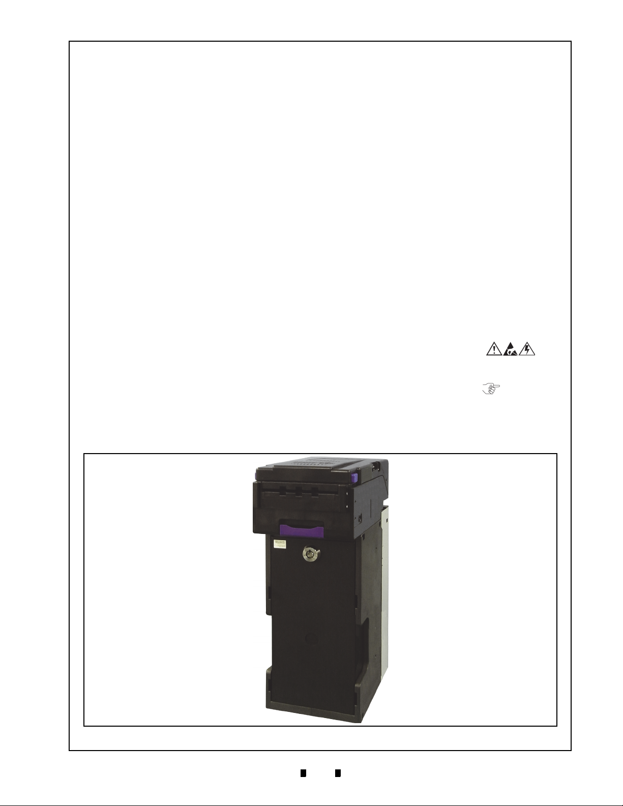
1
EBA® Series
1 GENERAL INFORMATION
EBA-40 Unit
Figure 1 EBA-40 Unit
Banknote Acceptor (EBA-40)
Integration Guide
Revision A
Description
This section provides a general overview of the
®
EBA
Series Banknote Acceptor Unit (EBA-40),
pictured in Figure 1. This section is designed to
help the user navigate through
It includes the following information:
• EBA-40 Unit
• Model Descriptions
• Type Descriptions
• Software Descriptions
• Precautions
• Primary Features
• Component Names
• Specifications
• Installation
• Connector Pin Assignments
• Preventive Maintenance
• Standard Interface Circuit
this guide with ease.
Schematics
• Operational Flowchart
• Troubleshooting
• Unit Dimensions
• International Compliance
• Technical Contact Information
In order to make operating this device and navigating within this manual easier
tions are used:
• Safety Instructions need to be obser
order to protect the operators and the
equipment; these are identified with bold text
and the following pictographs:
pecial Notes affect the use of the Banknote
• S
Acceptor; these are identified with italic text
and the following pictograph:
• St
eps require the operator to perform specific
actions; these are identified with sequential
numbers (1, 2, 3, etc.).
, the following illustra-
ved in
P/N 960-000173R_Rev. A {EDP #229278} © 2013, JAPAN CASH MACHINE CO., LTD.
Page 10
2
EBA® Series Banknote Acceptor (EBA-40) Integration Guide
Type 1 Type 2 Type 3
Figure 2 Precautionary Symbols
Model Descriptions
Table 1 lists the product model number
descriptions.
Table 1 EBA-40 Model Number
o
N
N
Model Number
(1)
4 = Standard
Model Series Number
(2)
0 = Standard
1-9 = Reserved
Model: EBA- * * - SD3
o
(1)(2)
Specifications
Type Descriptions
Table 2 lists the product type number descriptions.
Table 2 EBA-40 Type Number Specifications
o
N
No (1) (2)(3)(4)(5)(6) (7)
(1)
Denomination (Country Code)
(2)
Cash Box Capacity
0 = None (Without Stacker)
4 = 400 notes (Standard)
(3) Bezel (Option)
0 = Without Bezel (Standard)
1 = Bezel Type A
(4) Interface Conversion Board
0 = Without I/F Conversion Board (Standard)
(5) Key Switch
0 = Without Key Switch (Standard)
1 = With Key Switch
2 = OEM Key Switch
(6) Bar Sensor
0 = Without Bar Sensor (Standard)
1 = With Bar Sensor (Up type)
2 = With Bar Sensor (Down type)
(7) Interface
03 = ID-003 (JCM Serial)
D3 = ID-0D3 (MDB)
E3 = ID-0E3 (ccTalk)
** = Other (Last 2 digits of interface ID)
*. The Country Code is indicated following the ISO 3166.
†. The numbers of stacked Notes depends on the Banknote’s condition.
‡. Serial communication protocol developed by MoneyControl is
employed for ccTalk.
Model: ***(*) - * * * * * - **
*
†
‡
Software Descriptions
Table 3 lists the software number descriptions.
Table 3 EBA-40 Software Number Specifications
o
N
(A)
(B)
(C) Interface Protocol Name
(D) Software Version
*. The Country Code is indicated following the ISO 3166.
Software: EBA-40 * * * - 0 * * - V * .**
No (A) (B) (C) (D)
Software Model Name
Denomination (Country Code)
*
Precautions
Symbols in Figure 2 are defined as follows:
1. (Type 1) Do not insert a torn, folded, or wet
Banknote; it may cause a jam inside the unit.
(Type 2) Do not expose the unit to water. The unit
2.
contains several precision electronic devices that
can be damaged if water or any liquid is sprayed
or spilled into the unit.
(Type 3) Do not install the unit in a dusty
3.
environment. Dust may af
sor’s performance.
U
SER CAUTIONS
Careful measures were taken in the design of this
product to ensure its quality; however, the following cautions pertain to all users and should be followed for safe operation.
Installation Cautions
The Installation Cautions are defined as follows:
1. Be sure the Host Machine contains enough
protection to avoid wet or dusty conditions when
installing the
The unit is not designed for outdoor installations.
2. Be sure the Host Machine is designed with
careful consideration for retrieving a Banknote
/or clearing a Banknote jam.
and
3. Be careful not to use excessive outside pressure
the Mounting Plate when removing the Cash
on
Box from the Unit.
4. Avoid exposing the Banknote Insertion Slot to
rect Sunlight and/or Incandescent Lamp
di
illumination having a Gradient Angle of 15
Deg
rees or more, and an illumination index of
3000 Lux or less. Insure that the Host Machine is
also designed to avoid exposing the Banknote
unit in an indoor or open-air space.
fect/degrade the sen-
P/N 960-000173R_Rev. A {EDP #229278} © 2013, JAPAN CASH MACHINE CO., LTD.
Page 11
3
EBA® Series Banknote Acceptor (EBA-40) Integration Guide
Caution: Turn the EBA-40 Unit’s Power
OFF when opening the Upper Tray;
otherwise, the Rollers may begin
operating and personal injury to fingers
may occur by getting them pulled into
the Unit.
Caution: Be careful to avoid personal
injury to your fingers when closing the
Upper Guide Section.
WARNING: Do not inject water or liquid
agents of any kind into the Acceptor, as
this may cause extreme damage to the
Unit.
WARNING: To minimize risk of damage
to internal printed circuit boards, never
allow excess fluid (e.g., from a wet
cleaning cloth) to drip or leak into the
device. Internal printed circuit boards
may be damaged. Do not use any
alcohol, citrus based cleaners, solvents
or scouring agents that can damage the
plastic surfaces of the device.
Caution: Make sure Interface Harness
connections to the Host Machine are
shorter than 9.84 Feet (3 Meters) in
length. Cut off all unused portions of
the Interface Harness wiring to avoid
static electrical effects or short circuit
possibilities that could cause damage
to the Unit.
WARNING: This Unit is designed for
use with a Current limiting Power
Source! Design the Host Cabinet space
to meet all local related safety
standards.
Insertion Slot to direct Sunlight or incandescent
light.
5. Do not allow the Acceptor to endure a range of
6. Do not use the Acceptor in environments
7. Do not use the Acceptor where it may be exposed
8. Clean and maintain the Acceptor regularly when
perature and humidity beyond the environ-
tem
mental limits specified (See “Environmental
Specifications” on page 7 of this Section).
may be subject to server temperature changes.
to airborne evaporated or s
located in an excess
ment.
poradic chemicals.
ively smoke filled environ-
that
Mounting, Dismounting & Transportation
Methods for mounting, dismounting and transporting the unit:
1. Be sure to turn the Power OFF before mounting
or removing the Unit from its permanent location.
Plugging or unplugging Connector Plugs from
their receptacles while the Power is ON may
cause damage to the Unit.
2. When reassembling a disasse
ensure that the each part is properly replaced in its
correct original location and the Acceptor is not
removed by pulling it forward.
3. Be sure to carry the Unit by both hands when
transportin
cause personal injury if the Unit accidentally
becomes disassembled and drops away.
4. Be careful not to use excessive outside press
on the Unit, or subject it to excessive vibration
during transportation.
g it. Holding the Unit by one hand may
mbled Unit Part,
ure
Placing Foreign Objects into the Unit
Observe the following precautions when placing
foreign objects into the Unit:
1. Do not insert anything except Banknotes into the
Insertion Slot. Inserting Receipts, Stapled Tickets,
Rubber Bands, or Credit Cards into the Unit may
damage the Banknote Transport path.
2. Do not inject liquids into the Banknote Insertion
ot. Injecting water, oil or cleaning agents may
Sl
damage the Sensors within the Banknote Transport path.
Preventive Maintenance
The preventive maintenance requirements are
defined as follows:
1. When closing the Upper Tray of the Acceptor,
ensure that it clicks firmly into place.
2. Do not redesign or disassemble the EBA-40
Acceptor
trained personnel, or use outside the original manufacturer’s intent for operation voids the warranty.
3. Perform routine cleaning and maintenance
once a month to keep the EBA-40 Unit’s performance stable.
4. Use a soft, lint-free clot
pressed air spray to clean dust and debris from the
Rollers.
5. If the Unit is exposed to water or liquids, use a
clean, dry
absorb excess liquids immediately. Any remaining liquids or fluids may affect and degrade the
Sensors and V
. Unauthorized use by inadequately
at least
h, cotton swab or com-
micro-fiber cloth to wipe off and
alidation component performance.
P/N 960-000173R_Rev. A {EDP #229278} © 2013, JAPAN CASH MACHINE CO., LTD.
Page 12

4
EBA® Series Banknote Acceptor (EBA-40) Integration Guide
Damaged Banknotes
Wrinkled Banknotes
Curled Banknotes
Folded or Partial Banknotes
Figure 3 Unacceptable Banknotes
6
2
m
m
-
8
5
m
m
Figure 4 Automatic Centering Mechanism
(with the SD3 Stacker)
Figure 5 Automatic Centering Mechanism
(without the SD3 Stacker)
6
0
m
m
-
8
5
m
m
B
ANKNOTE FITNESS REQUIREMENTS
The following Banknote types may not validate
correctly, or worse, can cause a jam and/or damage
to the unit’s Transport Path.
Banknotes exhibiting the following conditions
illustrated in Figure 3 should be avoided:
• torn
• excessive folds or wrinkles
• dirty
• wet
• containing foreign objects and/or oil
Primary Features
The EBA-40 Banknote Acceptor Unit contains the
following primary features:
•
Proven Anti-Pullback Technology – This JCM
patented Anti-Pullback Mechanism provides
powerful protection against Banknote
stringing.
Automatic Centering – The Centering
•
Mechanism (See Figure 4 & Figure 5) allows
the unit to read Banknote without using speci
Banknote Guides. It helps to improve the
overall acceptance rate:
– With the SD3 Stacker: 62mm to 85mm in width
– Without the SD3 Stacker: 60mm to 85mm in
width.
al
P/N 960-000173R_Rev. A {EDP #229278} © 2013, JAPAN CASH MACHINE CO., LTD.
Page 13
5
EBA® Series Banknote Acceptor (EBA-40) Integration Guide
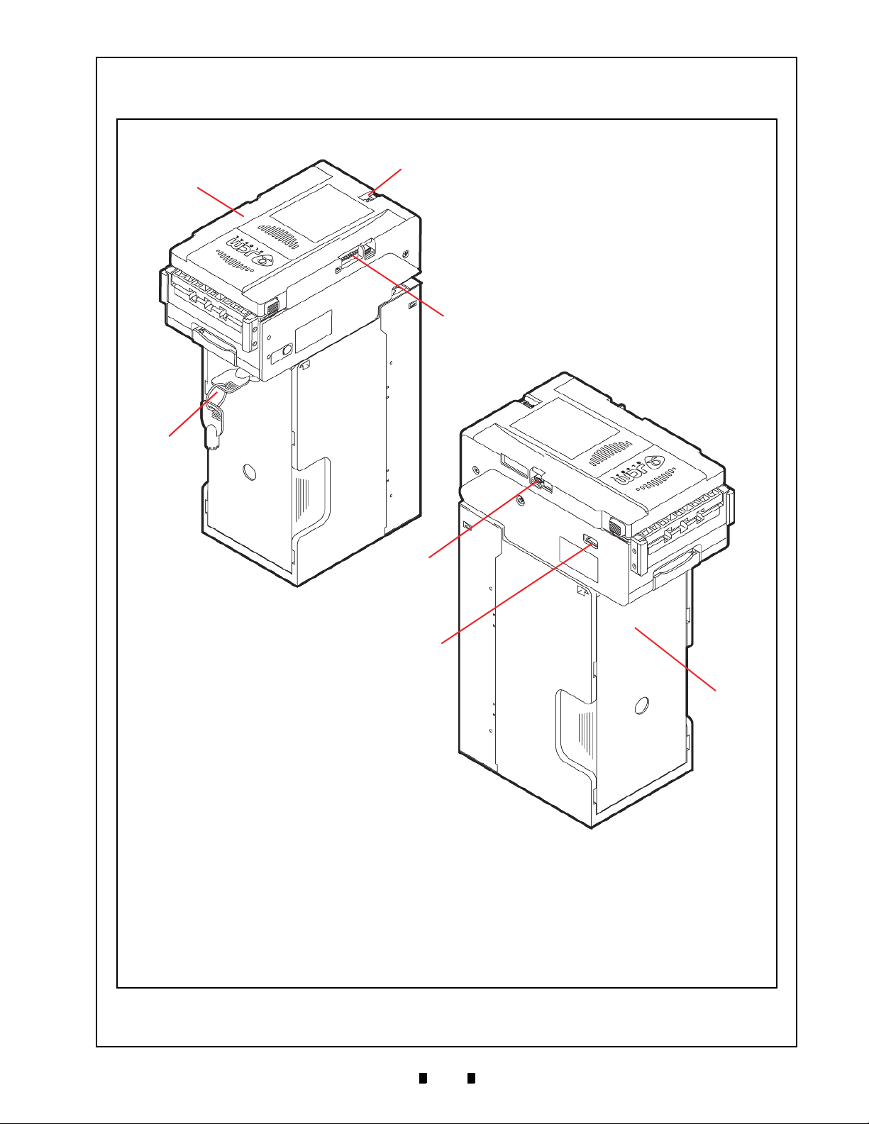
Figure 6 EBA-40 Component Names
a) Acceptor Unit
b) DIP Switch Block 2
c) DIP Switch Block 1
d) Coin Lock
e) Interface Connector
f) External Display Connector
g) SD3 Stacker Box
b
c
d
e
f
g
a
Component Names
Figure 6 illustrates the EBA-40 component names and locations.
P/N 960-000173R_Rev. A {EDP #229278} © 2013, JAPAN CASH MACHINE CO., LTD.
Page 14
6
EBA® Series Banknote Acceptor (EBA-40) Integration Guide
2 SPECIFICATIONS
Technical Specifications
Table 4 EBA-40 Technical Specifications
98% or greater
Note: The following banknote types are excluded:
• Banknotes with excess or poor magnetism or unclear graphics
Acceptance Rate
*
:
Banknote Types Accepted:
Barcode Coupon†:
Insertion Direction: Refer to the Specific Country’s “Software Information Sheet”
Processing Speed‡:
Validation Method: Validation Sensor and Magnetic Sensor
Diagnostic Indicators: LED (Green/Red), External Display Output
Escrow: 1 Note
Anti-stringing Mechanism: Pull-Back (PB) Unit (Anti-pullba
Cash Box Capacity
**
:
Cash Box Access: Front Access
††
Interface
*. Refer to the specific Country’s “Software Information Sheet” for each Country’s particular Banknote acceptance rate.
†. Refer to the specific Country’s “Bar Code Coupon Specification” for more details.
‡. Excluding Host Communication time lag (Power Supply: +12V DC, Temperature: 25º C ±5º C, Humidity: 30%-60%).
**.The number of Notes stacked depends on the Banknote’s condition.
††.The Interface Harness connecting to the Host should be less than 3m(9.84 ft).
:
• Double (dual) Notes
• Worn, dirty, wet, stained, torn or excessively wrinkled Banknotes
• Banknotes having folded corners or edges
• Banknotes having the wrong cut dimensions or printing displacement
• Returned Banknotes because of incorrect or failed insertion.
With the SD3 Stacker
• Long side: 120-160mm (4.72-6.29 in.)
• Short side: 62-85mm (2.44-3.34 in.)
Without the SD3 Stacker
• Long side: 110-181mm (4.33-7.12 in.)
• Short side: 60-85mm (2.36-3.34 in.)
Standard Specification
• Read code interleaved: 2 of 5
• Narrow Bar: 0.5-0.6mm (0.019-0.023 in.)
• Wide Bar to Narrow Bar ratio = 3:1
• Characters: 18 Characters
• Print Position: Middle (Divides a Coupon equally from the left, right, top and
bottom of the Coupon’s center)
• Print Width: Wider than 10mm (0.39 in.)
Approximately 1.8 seconds
(from Banknote insertion to sending Vend Signal)
Approximately 3.5 seconds
(from Banknote insertion t
o stacking completion)
ck System - JCM Patented)
Approximately 400 notes (new Banknotes)
TTL Serial Interface
MDB Interface
ccTalk
RS232C
USB (USB Specification Rev. 2.0 Co
mpliance) (Full Speed/12Mbps)
P/N 960-000173R_Rev. A {EDP #229278} © 2013, JAPAN CASH MACHINE CO., LTD.
Page 15

7
EBA® Series Banknote Acceptor (EBA-40) Integration Guide
Hydrothermal Condition Table
Humidity [%RH]
Temperature [ºC]
Allowable
and Humidity Range
Operating
Temperature
50ºC/40RH%
35ºC/80RH%
Environmental Specifications
Table 5 EBA-40 Environmental Specifications
Operating Temperature:
Storage Temperature:
5ºC to +50ºC (41ºF to 122ºF)
-20ºC to +60ºC (-4ºF to 140ºF)
Relative Operating Humidity: 30% to 85% RH (non-condensed)
Relative Storage Humidity: 30% to 85% RH (non-condensed)
Visible Light Sensitivity:
Avoid contact with direct sunlight
Radiant Angle of 15 Degrees or more having an Illu
Installation: Indoors Only
*. Depends on hydrothermal conditions.
*
*
(Interior lighting must be incandescent with a
mination index of 3000 Lux or less)
Electrical Specifications
pecifications
*
Supply Voltage:
Current Consumption:
*. Use a Current Source Limiting Power Supply
Table 6 EBA-40 Electrical S
12V DC ±5% (Greater than 3A)
24V DC ±5% (Greater than 1.6A)
12V DC
• Standby = 180mA
• Operation = 1.0A
• Peak = 3.0A
24V DC
• Standby = 110mA
• Operation = 0.6A
• Peak = 1.6A
Structural Specifications
Tab le 7 EBA-
Weight:
With the SD3 Stacker: Approximately 2.5kg (5.51lbs.)
Without the SD3 Stacker: Ap
Mounting: Horizontal
Outside Dimensions: See “Entire Unit Outside Dimensions” on page 33 of this Manual
40 Structural Specifications
proximately 1kg (2.2lbs.)
P/N 960-000173R_Rev. A {EDP #229278} © 2013, JAPAN CASH MACHINE CO., LTD.
Page 16

8
EBA® Series Banknote Acceptor (EBA-40) Integration Guide
84mm
60mm
50mm
a
1
a
2
a
3
a
4
84mm
60mm
50mm
a
1
a
2
a
3
a
4
60mm
50mm
a
1
a
2
a
3
a
4
Figure 7 M3 Screw Locations (Bottom)
WARNING: The maximum length of the
M3 Screws should be selected
considering the Cabinet or Mounting
Bracket thickness. The Mounting
Screws’ length should not extend more
than 8mm upward from the bottom of
the SD3 Stacker Box Frame.
Key
84mm
Ø6
Ø
1
0
74mm
Rear View
9.5mm
Hole Slots
Figure 8 Key Hole Slot Locations (Rear)
1
0
5
m
m
9
1
.
7
m
m
a
1
a
2
a
3
a
4
c
1
c
2
b
Figure 9 M4 Screw Locations (Rear & Bottom)
3 INSTALLATION
This section provides installation and operating
instructions for the EBA-40 Banknote Acceptor
unit. The information within this section contains
the following features:
• Installation Procedure
• Lock Installation
• DIP Switch Configuration
Installation Procedure
The EBA-40 Frame Unit provides installation holes
for each surface.
E
NTIRE UNIT INSTALLATION
Perform the following steps to install the EBA-40
Unit:
1. Place the EBA-40 Unit Frame in its intended
mounting location.
2. Bolt the bottom side of the EBA-40 Frame into its
tended location using four (4) M3 Screws
in
(See Figure 7 a
the Frame when this mounting configuration is
preferred.
through a4) from the outside of
1
3. Hang the EBA-40 Frame onto shafts which fit in
place for
the proper width and length of the Key
Hole Slots on the rear side of the Frame when this
mounting configuration is preferred (See Figure
8).
A
CCEPTOR HEAD INSTALLATION
Perform the following steps to install the EBA-40
Acceptor Head Assembly using the Mounting
Bracket:
1. Place the EBA-40 Acceptor Head in its intended
mounting location.
2. Install the Mounting Bracket into its intended
cation using four (4) M4x6 Screws (See Figure
lo
9 a
through a4) provided with the Mounting
1
Bracket.
3. Slide and install the EBA-40
Assembly (See Figure 9 b) onto the Mounting
Bracket while simultaneously sliding the “Pedestal Rail
” (See Figure 9 c
this mounting configuration is preferred.
Acceptor Head
& c2) in place when
1
P/N 960-000173R_Rev. A {EDP #229278} © 2013, JAPAN CASH MACHINE CO., LTD.
Page 17

9
EBA® Series Banknote Acceptor (EBA-40) Integration Guide
Bottom View
3
7
m
m
2
5
m
m
c1-c
6
1
2
m
m
4
0
m
m
4
2
m
m
Attention
Do not use screws
longer than 5mm
JCM GLOBAL
b
a1-a
6
Figure 10 M3 Screw Locations (Rear & Bottom)
WARNING: The maximum length of the
M3 Screws should be selected
considering the Cabinet or Mounting
Bracket thickness. The Mounting
Screws’ length should not extend more
than 4mm upward from the bottom of
the SD3 Stacker Box Frame and the
Lower Cover.
Figure 11 Key Hole Location
Key Hole
1
7
.
4
m
m
15.8 mm
Ø1
9
.
5
Tan g
(Front)
Figure 12 Lock Dimension & Cylinder Length
NOTE: Make sure the Tang is correctly installed,
as illustrated in Figure 12.
Perform the following steps to install the EBA-40
Acceptor Head Assembly without the Mounting
Bracket:
1. Confirm the six (6) installation holes (See Figure
10 a
through a6) on the Lower Cover (See Figure
1
10 b) located on the
Acceptor Head Assembly.
2. Place the EBA-40 Acceptor Head Assembly in its
ended mounting location.
int
3. Bolt the Lower Cover of the
Head Assembly into its intended location using
six (6) M3 Screws (See Figure 10 c
from the bottom side of the Frame when this
unting configuration is preferred.
mo
bottom side of the EBA-40
EBA-40 Acceptor
through c6)
1
Lock Installation
One security lock can be installed onto the EBA-40
SD3 Stacker. When installing a security lock, the
following attachment accessories may be required:
• Tang
Choose a Lock that fits a standard 17.4 mm cylinder length format. This is the only format that
supported. (See Figure 12).
is
P/N 960-000173R_Rev. A {EDP #229278} © 2013, JAPAN CASH MACHINE CO., LTD.
Page 18

10
EBA® Series Banknote Acceptor (EBA-40) Integration Guide
NOTE: There are many lock designs. Locks vary
greatly in price, security, keying policies, etc..
The customer is responsible for selecting a lock
that is appropriate for the intended purpose.
JCM does not test or endorse any commercially
available brand of lock for its security
characteristics.
Figure 13 Key Unlock Rotation Requirement
Unlock
DS1
DS2
DIP Switch Configurations
This section provides the denomination DIP Switch
Block 1 (DS1) and 2 (DS2) Settings for the
EBA-40 Unit.
Tab le 8 DIP Switch Block 1 Settings
Switch
No.
1
2
3
4
5
6
7
8
Table 9 DIP Switch Block 2 Settings
Switch ON Switch OFF
VEND 1 INHIBIT VEND 1 ACCEPT
VEND 2 INHIBIT VEND 2 ACCEPT
VEND 3 INHIBIT VEND 3 ACCEPT
VEND 4 INHIBIT VEND 4 ACCEPT
VEND 5 INHIBIT VEND 5 ACCEPT
VEND 6 INHIBIT VEND 6 ACCEPT
VEND 7 INHIBIT VEND 7 ACCEPT
TEST MODE FUNCTION
Switch
No.
1
2
3
4
5
6
7
8
Switch ON Switch OFF
With SD3 Stacker Without SD3 Stacker
Key Switch Enabled Key Switch Disabled
ccTalk (Encrypted) ccTalk (Non-Encrypted )
RS232C Interface Other Interface
With Barcode Sensor
Board
Reserved Reserved
Reserved Reserved
Reserved Reserved
Without Barcode Sensor
Board
P/N 960-000173R_Rev. A {EDP #229278} © 2013, JAPAN CASH MACHINE CO., LTD.
Page 19
11
EBA® Series Banknote Acceptor (EBA-40) Integration Guide
4 CONNECTOR PIN ASSIGNMENTS
Table 10 through Table 18 list the EBA-40 Unit’s pin assignments.
Table 10 lists the EBA-40 TTL Interface Pin Assignments.
Table 10 EBA-40 TTL Interface Pin Assignments
Header: XG4C-1634 (OMRON)
Housing: XG5M-1635-N Slit Wire (OMRON)
Recommended Wire: UL1007 AWG#26-28
Housing: XG4M-1630-T Flat Cable (OMRON)
Recommended Wire: UL2651 AWG#28
Pin No. Signal Name
I/O
*
1 +12V/+24V -
2 GND
3 +12V/+24V
4 GND
5 TTL - TXD
6 SG
7 TTL - RXD
8 ccTalk TXD/RXD
9 MDB - TXD
10 MDB - RXD
11 MDB COM
-
-
-
OUT
-
IN
IN/OUT
OUT
IN
-
12 I/F 12V No Connection
OR
Power Supply
GND
Power Supply
GND
TTL Communication Output Signal Line
Signal GND
TTL Communication Input Signal Line
No Connection
No Connection
No Connection
No Connection
Function
13 PC - TXD
OUT
14 I/F GND
15 SW - IN
16 PC - RXD
*. I/O (input/output) is the terminal as viewed from the Banknote Acceptor’s backside.
No Connection
No Connection
-
No Connection
IN
No Connection
IN
P/N 960-000173R_Rev. A {EDP #229278} © 2013, JAPAN CASH MACHINE CO., LTD.
Page 20

12
EBA® Series Banknote Acceptor (EBA-40) Integration Guide
CONNECTOR PIN ASSIGNMENTS (Continued 1)
Table 11 lists the EBA-40 MDB Interface Pin Assignments.
Table 11 EBA-40 MDB Interface Pin Assignments
Header: XG4C-1634 (OMRON)
Housing: XG5M-1635-N Slit Wire (OMRON)
Recommended Wire: UL1007 AWG#26-28
Housing: XG4M-1630-T Flat Cable (OMRON)
Recommended Wire: UL2651 AWG#28
Pin No. Signal Name
I/O
*
1 +12V/+24V -
2 GND
3
+12V/+24V
4 GND
5 TTL - TXD
6 SG
7 TTL - RXD
8 ccTalk TXD/RXD
9 MDB - TXD
10 MDB - RXD
11 MDB COM
-
-
-
OUT
-
IN
IN/OUT
OUT
IN
-
12 I/F 12V No Connection
13 PC - TXD
14 I/F GND
15 SW - IN
16 PC - RXD
*. I/O (input/output) is the terminal as viewed from the Banknote Acceptor’s backside.
OUT
-
IN
IN
OR
Function
Power Supply
GND
Power Supply
GND
No Connection
No Connection
No Connection
No Connection
MDB Communication Output Signal Line
MDB Communication Input Signal Line
MDB Common Signal Line
No Connection
No Connection
No Connection
No Connection
P/N 960-000173R_Rev. A {EDP #229278} © 2013, JAPAN CASH MACHINE CO., LTD.
Page 21

13
EBA® Series Banknote Acceptor (EBA-40) Integration Guide
CONNECTOR PIN ASSIGNMENTS (Continued 2)
Table 12 lists the EBA-40 ccTalk Interface Pin Assignments.
Table 12 EBA-40 ccTalk Interface Pin Assignments
Header: XG4C-1634 (OMRON)
Housing: XG5M-1635-N Slit Wire (OMRON)
Pin No. Signal Name
Recommended Wire: UL1007 AWG#26-28
Housing: XG4M-1630-T Flat Cable (OMRON)
Recommended Wire: UL2651 AWG#28
*
I/O
OR
Function
1
+12V/+24V
2 GND
3
+12V/+24V
4 GND
5 TTL - TXD
OUT
6 SG
7 TTL - RXD
8 ccTalk TXD/RXD
IN/OUT
9 MDB - TXD OUT
10 MDB - RXD
11 MDB COM
Power Supply
-
GND
-
Power Supply
-
GND
-
No Connection
Signal GND
-
No Connection
IN
ccTalk Communication Input/Output Signal Line
No Connection
No Connection
IN
No Connection
-
12 I/F 12V No Connection
13 PC - TXD
OUT
14 I/F GND
15 SW - IN
16 PC - RXD
*. I/O (input/output) is the terminal as viewed from the Banknote Acceptor’s backside.
No Connection
No Connection
-
No Connection
IN
No Connection
IN
P/N 960-000173R_Rev. A {EDP #229278} © 2013, JAPAN CASH MACHINE CO., LTD.
Page 22

14
EBA® Series Banknote Acceptor (EBA-40) Integration Guide
CONNECTOR PIN ASSIGNMENTS (Continued 3)
Table 13 lists the EBA-40 Photo-Coupler Interface Pin Assignments.
Table 13 EBA-40 Photo-Coupler Interface Pin Assignments
Header: XG4C-1634 (OMRON)
Housing: XG5M-1635-N Slit Wire (OMRON)
Pin No. Signal Name
Recommended Wire: UL1007 AWG#26-28
Housing: XG4M-1630-T Flat Cable (OMRON)
Recommended Wire: UL2651 AWG#28
*
I/O
OR
Function
1 +12V/+24V -
2 GND
3
+12V/+24V
4 GND
5 TTL - TXD
6 SG
7 TTL - RXD
8 ccTalk TXD/RXD
IN/OUT
9 MDB - TXD
10 MDB - RXD
11 MDB COM
OUT
OUT
Power Supply
GND
-
Power Supply
-
GND
-
No Connection
No Connection
-
No Connection
IN
No Connection
No Connection
No Connection
IN
No Connection
-
12 I/F 12V Photo-Coupler Communication Interface Power Supply 12V
13 PC - TXD
OUT
14 I/F GND
15 SW - IN
16 PC - RXD
*. I/O (input/output) is the terminal as viewed from the Banknote Acceptor’s backside.
Photo-Coupler Communication Output Signal Line
Photo-Coupler Communication Interface GND
-
No Connection
IN
Photo-Coupler Communication Input Signal Line
IN
P/N 960-000173R_Rev. A {EDP #229278} © 2013, JAPAN CASH MACHINE CO., LTD.
Page 23

15
EBA® Series Banknote Acceptor (EBA-40) Integration Guide
CONNECTOR PIN ASSIGNMENTS (Continued 4)
Table 14 lists the EBA-40 RS232C Interface Pin Assignments.
Table 14 EBA-40 RS232C Interface Pin Assignments
Header: XG4C-1634 (OMRON)
Housing: XG5M-1635-N Slit Wire (OMRON)
Pin No. Signal Name
Recommended Wire: UL1007 AWG#26-28
Housing: XG4M-1630-T Flat Cable (OMRON)
Recommended Wire: UL2651 AWG#28
*
I/O
OR
Function
1 +12V/+24V -
2 GND
3 +12V/+24V
4 GND
5 TTL - TXD
6 SG
7 TTL - RXD
8 ccTalk TXD/RXD
IN/OUT
9 MDB - TXD
10 MDB - RXD
11 MDB COM
OUT
OUT
Power Supply
GND
-
Power Supply
-
GND
-
No Connection
No Connection
-
No Connection
IN
No Connection
No Connection
No Connection
IN
No Connection
-
12 I/F 12V No Connection
13 PC - TXD
OUT
14 I/F GND
15 SW - IN
16 PC - RXD
*. I/O (input/output) is the terminal as viewed from the Banknote Acceptor’s backside.
No Connection
No Connection
-
No Connection
IN
No Connection
IN
Table 15 lists the EBA-40 CN13 RS232C Connector Pin Assignments.
Table 15 EBA-40
Pin No. Signal Name I/O Function
1 RS232C - TXD OUT
2 RS232C - RXD
3 SG
P/N 960-000173R_Rev. A {EDP #229278} © 2013, JAPAN CASH MACHINE CO., LTD.
CN13 RS232C Connector Pin Assignments
Header: 53426-0310 (MOLEX)
Housing: 51103-0300 (MOLEX)
Recommended Wire: UL1007 AWG#22-28
Contact: 50351-8000
RS232C Communication Output Signal Line
RS232C Communication Input Signal Line
IN
Signal GND
-
Page 24
16
EBA® Series Banknote Acceptor (EBA-40) Integration Guide
CONNECTOR PIN ASSIGNMENTS (Continued 5)
Table 16 lists the EBA-40 USB Interface Pin Assignments.
Table 16 EBA-40 USB Interface Pin Assignments
Header: XG4C-1634 (OMRON)
Housing: XG5M-1635-N Slit Wire (OMRON)
Pin No. Signal Name
Recommended Wire: UL1007 AWG#26-28
Housing: XG4M-1630-T Flat Cable (OMRON)
Recommended Wire: UL2651 AWG#28
*
I/O
OR
Function
1 +12V/+24V -
2 GND
3 +12V/+24V
4 GND
5 TTL - TXD
6 SG
7 TTL - RXD
8 ccTalk TXD/RXD
IN/OUT
9 MDB - TXD
10 MDB - RXD
11 MDB COM
OUT
OUT
Power Supply
GND
-
Power Supply
-
GND
-
No Connection
No Connection
-
No Connection
IN
No Connection
No Connection
No Connection
IN
No Connection
-
12 I/F 12V No Connection
13 PC - TXD
OUT
14 I/F GND
15 SW - IN
16 PC - RXD
*. I/O (input/output) is the terminal as viewed from the Banknote Acceptor’s backside.
No Connection
No Connection
-
No Connection
IN
No Connection
IN
P/N 960-000173R_Rev. A {EDP #229278} © 2013, JAPAN CASH MACHINE CO., LTD.
Page 25

17
EBA® Series Banknote Acceptor (EBA-40) Integration Guide
CONNECTOR PIN ASSIGNMENTS (Continued 6)
Table 17 lists the EBA-40 CN3 mini-B Connector Pin Assignments.
Table 17 EBA-40 CN3 mini-B Connector Pin Assignments
Header: MNC20-5K5P10 [USB mini-B Type] (ACON)
Housing: USB mini-A Type
Pin No. Signal Name I/O Function
1 Vbus -
2 D-
3 D+
4 -
IN/OUT
IN/OUT
5 USB GND
USB Communication Vbus Signal Line
USB Communication Input/Output Signal Line
-
USB Communication Input/Output Signal Line
No Connection
USB Communication GND
-
Table 18 lists the EBA-40 CN2 Bezel Connector Pin Assignments.
Table 18 EBA-
Pin No. Signal Name I/O Function
1 +12V -
2 GND
3 BZLED_1
4 BZLED_2
5 BZLED_3
6 BZLED_4
7 BZLED_5
40 CN2 Bezel Connector Pin Assignments
Header: S7B-ZR-3.4 (JST)
Housing: ZHR-7 (JST)
Contact: SZH-002T-P0.5 (MOLEX)
Recommended Wire: UL1061 AWG#26-28
Power Suppl
GND
-
LED Drive Line (Cathode)
-
LED Drive Line (Cathode)
-
LED Drive Line (Cathode)
-
LED Drive Line (Cathode)
-
LED Drive Line (Cathode)
-
P/N 960-000173R_Rev. A {EDP #229278} © 2013, JAPAN CASH MACHINE CO., LTD.
Page 26

18
EBA® Series Banknote Acceptor (EBA-40) Integration Guide
5 PREVENTIVE MAINTENANCE
a
b
Figure 14 Retrieving Banknotes
a
b
c
Figure 15 Clearing an Entrance Banknote Jam
a
b
Figure 16 Clearing a Stacker Box Banknote Jam
NOTE: If a Banknote jam occurs when the
Centering Mechanism is closed, the cover
will not open. To un-jam the Unit, rotate the
Centering Guide Shaft out of the way by
using a Hex Nut Driver, and then open the
Top Cover and remove the jam.
Caution: Do not use Alcohol, thinner or
Citrus based products for cleaning any
Banknote transport Sensors or
surfaces. The lenses can become
clouded by chemical evaporation
residue that may cause acceptance
errors.
Retrieving Banknotes
To retrieve Cash Box deposited Banknotes, perform
the following steps:
1. Unlock the Stacker Box lock using the supplied
Coin Key (See Figure 14 a).
2. Pull the Stacker Box out
(See Figure 14 b) and ret
of the Frame Housing
rieve the Banknotes.
Clearing a Banknote Jam
To retrieve a jammed Banknote located inside the
Banknote Acceptor, proceed as follows:
1. Pull the Tabs (See Figure 15 a) located on the
both sides of the Acceptor As
Unit’s Front Cover (See Figure 15 b).
2. Remove the jammed Banknote (See Figure 15 c).
sembly to open the
4. Remove any jammed Banknote found there
(See Figure 16 b).
Cleaning Procedure
To clean the EBA-40 Validation Section, gently rub
the Sensors and Rollers clean using a dry, soft,
lint-free, Micro-fiber Cloth ONLY.
Do not use any Alcohol, solvents, Citrus based
products or scouring agents that may cause damage
the Validation Section Sensors and/or Rollers.
to
S
ENSOR AND ROLLER CLEANING PROCEDURE
To clean the EBA-40 Unit’s Sensors and Rollers,
proceed as follows:
1. Turn the EBA-40 Unit and the Host Machine’s
Power Supply’s OFF.
2. Open the EBA-40 Units Front and Rear Guide.
3. Clean the appropriate path
Sensor.
and Lens of each
3. If the Banknote jam location is still not evident,
P/N 960-000173R_Rev. A {EDP #229278} © 2013, JAPAN CASH MACHINE CO., LTD.
and pull the Stacker Box out of the Frame
unlock
Unit (See Figure 16 a).
Page 27

19
EBA® Series Banknote Acceptor (EBA-40) Integration Guide
Lens
Roller
Lint-free Cloth Cotton Swab Air Jet
Before
Cleaning
After
Cleaning
Belt
Figure 17 Sensor Cleaning
NOTE: Calibration is recommended after
cleaning.
Figure 18 EBA-40 Sensor and Roller Cleaning Locations
h
e
g
a
d
f
b
a
b
e
c
Anti-Pullback System
c
Note: Clean Rollers using a damp, lint-free, Micro-fiber Cloth.
Note: Clean the Anti-pullback
System with Compressed Air.
h
g
S
ENSOR AND ROLLER LOCATIONS
Figure 18 illustrates the various EBA-40 Unit’s
sensor cleaning locations. Table 19 lists the
EBA-40 sensor type cleaning methods.
Table 19 EBA-40 Sensor Type Cleaning Methods
Sym. Sensor/Roller Type Sym. Sensor/Roller Type Cleaning Method
a
Entrance Sensor
b Centering Guide Timing Sensor f Magnetic Sensor
c Validation Sensor g Anti-Pullback Exit Sensor
d Anti-Pullback Entrance Sensor h Exit Sensor
*. Either the Upper or Lower Barcode Sensor is required.
e
Barcode Sensor (Option)
*
Wipe clean using a
soft lint-free cloth or
blow clean using
compressed air.
P/N 960-000173R_Rev. A {EDP #229278} © 2013, JAPAN CASH MACHINE CO., LTD.
Page 28

20
EBA® Series Banknote Acceptor (EBA-40) Integration Guide
CONTROLLER SIDE
EBA SIDE
Figure 19 EBA-40 TTL Interface Schematic Diagram
CONTROLLER SIDE
EBA SIDE
Figure 20 EBA-40 MDB Interface Schematic Diagram
6 STANDARD INTERFACE CIRCUIT SCHEMATICS
Figure 19 illustrates the EBA-40 TTL Interface Schematic Diagram.
Figure 20 illustrates the EBA-40 MDB Interface Schematic Diagram.
P/N 960-000173R_Rev. A {EDP #229278} © 2013, JAPAN CASH MACHINE CO., LTD.
Page 29

21
EBA® Series Banknote Acceptor (EBA-40) Integration Guide
CONTROLLER SIDE
EBA SIDE
Figure 21 EBA-40 ccTalk Interface Schematic Diagram
CONTROLLER SIDE
EBA SIDE
Figure 22 EBA-40 Photo-Coupler Interface Schematic Diagram
STANDARD INTERFACE CIRCUIT SCHEMATICS (Continued 1)
Figure 21 illustrates the EBA-40 ccTalk Interface Schematic Diagram.
Figure 22 illustrates the EBA-40 Photo-Coupler Interface Schematic Diagram.
P/N 960-000173R_Rev. A {EDP #229278} © 2013, JAPAN CASH MACHINE CO., LTD.
Page 30

22
EBA® Series Banknote Acceptor (EBA-40) Integration Guide
CONTROLLER SIDE
EBA SIDE
Figure 23 EBA-40 RS232C Interface Schematic Diagram
CONTROLLER SIDE
EBA SIDE
Figure 24 EBA-40 USB Interface Schematic Diagram
STANDARD INTERFACE CIRCUIT SCHEMATICS (Continued 2)
Figure 23 illustrates the EBA-40 RS232C Interface Schematic Diagram.
Figure 24 illustrates the EBA-40 USB Interface Schematic Diagram..
P/N 960-000173R_Rev. A {EDP #229278} © 2013, JAPAN CASH MACHINE CO., LTD.
Page 31

23
EBA® Series Banknote Acceptor (EBA-40) Integration Guide
CONTROLLER SIDE
EBA SIDE
Figure 25 EBA-40 Bezel LED Interface Schematic Diagram
STANDARD INTERFACE CIRCUIT SCHEMATICS (Continued 3)
Figure 25 illustrates the EBA-40 Bezel LED Interface Schematic Diagram.
P/N 960-000173R_Rev. A {EDP #229278} © 2013, JAPAN CASH MACHINE CO., LTD.
Page 32

24
EBA® Series Banknote Acceptor (EBA-40) Integration Guide
b) Initializing
c) Stand-by
d) Enable Acceptance?
f) External LED Display shows Enable Accept
Pattern
g) Inserted the Banknote?
h) Intake the Banknote
i) Centering the Banknote
j) Start Transporting the Banknote
k) Sampling the Banknote Data
A) To “Validation” Flow (See Figure 27)
l) Stop Transporting the Banknote
C) Return from “Stacking” Flow (See Figure 28)
a) Apply Power to the Unit.
e) External LED Display shows No Accept
Pattern
Figure 26 EBA-40 Operational Flowchart (Initializing)
7 OPERATIONAL FLOWCHART
Figure 26 depicts Part One of a typical EBA-40 Initialization Banknote acceptance flow process.
P/N 960-000173R_Rev. A {EDP #229278} © 2013, JAPAN CASH MACHINE CO., LTD.
Page 33

25
EBA® Series Banknote Acceptor (EBA-40) Integration Guide
a) Is the Banknote Authentic?
b) Is the Banknote acceptable?
d) Has STACK Command been received?
D) To “f” function on this chart
e) Return the Banknote
h) Retried Acceptance Operation three times?
i) VEND Signal Output?
j) Stop operation (Abnormal Signal Output)(*1)
A) From “Initialize” Flow (See Figure 26)
c) Denomination Signal Output?
g) Is the Banknote transported to Stacker?
D) To “f” function on this chart
f) Transporting the Banknote
B) To “Stacking” Flow (See Figure 28)
*1). When an abnormal signal is received, remove and reapply Power to the EBA-40 Unit after resolving the problem, or send
a RESET Command from the Host Machine.
Figure 27 EBA-40 Operational Flowchart (Validation)
a) Stack the Banknote
b) Is the Cash Box full?
c) Stop operation (Stacker Full Signal Output)(*2)
B) From “Validation” Flow (See Figure 27)
C) To “Initializing” flow (See Figure 26)
*2). When a “Cash Box Full” Signal is received, retrieve the Banknotes from the Cash Box and re-seat the Cash Box back into
the Unit. The EBA-40 Unit will automatically perform its re-initialization movement operation.
Figure 28 EBA-40 Operational Flowchart (Stacking)
Operational Flowchart (Continued 1)
Figure 27 depicts Part Two of a typical EBA-40 Validation Banknote acceptance flow process.
Figure 28 depicts Part Three of a typical EBA-40 Stacking Banknote acceptance flow process.
P/N 960-000173R_Rev. A {EDP #229278} © 2013, JAPAN CASH MACHINE CO., LTD.
Page 34

26
EBA® Series Banknote Acceptor (EBA-40) Integration Guide
8 TROUBLESHOOTING
This section provides troubleshooting instructions
for the EBA-40 Banknote Acceptor Units, including the following information:
• Introduction
• Troubleshooting Overview
• Fault Table Listings
• LED Indication Conditions
Introduction
Most Banknote Acceptor failures result from minor
causes. Before replacing any parts, be sure that all
assembly and circuit board connectors are properly
fitted, with their harnesses properly connected.
Poor performance by the EBA-40 Banknote Acceptor is often caused when dust or foreign objects
adhere to the
Banknote insertion section first, then carefully
observe the operating state of the Acceptor when
re-initializing power. This observation is important
Symptoms/Error
Me
Banknote Acceptor is
not working
(does not accept any
Ba
Banknote jams occur
sensors or transport belt. Clean the
ssages
nknotes)
often
Possible Fault Causes Corrective Action Required
No external Power is applied to
he Banknote Acceptor
t
(+12/24V DC & GND)
Wrong or inappropriate
connections
Corrupted Software.
CPU Board failure.
A pressure Roller is dirty or
A pressure Roller Spring is
A foreign object is lodged in
the Transport path and/or
properly seated all the way
(the Acceptor Unit’s Latch
Release Levers are not locked
Banknote is wider than 85 mm
or narrower than 62mm (60mm
without the Stacker) (out of the
damaged.
loose or missing.
inside the Cash Box.
The Acceptor Unit is not
into the Frame
onto the Frame).
EBA Banknote width
specifications).
Table 20 General Fault Conditions
Verify that the Power Supply +12/24V DC and Ground Cables are connected
to their appropriate Pins on the main connector.
NOTE: The small LED to the left of the DS1 DIP Switches indicates power
available when lit.
Verify that all Harness Connectors are properly seated.
Check for any bent, missing or damaged Pins in the Connector Plugs and
mating Receptacles.
Re-download the correct Software.
Conduct an Initial Operational Test. If the test result is Negative (NG), replace
the CPU Board. Make sure to re-calibrate the Sensors after CPU Board is
replaced.
Clean all Pressure Rollers.
Replace as necessary.
Check all Pressure Roller Springs using a finger pressure test.
Replace as necessary.
Clean the Transport path and remove any foreign object discovered.
Re-seat the Acceptor Unit back into the Frame so it is firmly seated all the
way back into the Frame so the Acceptor Unit Release Lever Latches
securely lock onto the Frame.
Use only Banknotes widths having the correct EBA Unit’s size specifications.
in locating any causes of failure and the possible
fault location.
Perform all repairs by referring to Calibration and
esting in Section 6 of the EBA-40 Service Man-
T
ual, and the Disassembly/Reassembly instructions
Section 4 of the EBA-40 Service Manual.
in
Troubleshooting Overview
This product allows the operator to perform fault
diagnosis by checking various Fault Table Listings
against the symptoms. Survey the cause(s) of any
failure occurrences during the process.
After determining the cause of the failure, execute
rformance Test, and then repair the unit
the Pe
replacing any appropriate parts deemed necessary.
Fault Table Listings
Table 20 lists the various possible EBA-40 Unit
fault conditions that can occur and
actions required to correct them.
the necessary
P/N 960-000173R_Rev. A {EDP #229278} © 2013, JAPAN CASH MACHINE CO., LTD.
Page 35

27
EBA® Series Banknote Acceptor (EBA-40) Integration Guide
Table 20 General Fault Conditions (Continued)
Symptoms/Error
Messages
Acceptance rates
Upper Guide can not
be opened
All Banknotes being
rejected
Motor
continues to run
Can not enter the
TEST mode
Possible Fault Causes Corrective Action Required
Dirt and/or stains on the
Rollers, Belts and Lenses.
The Unit has been
disassembled, and calibration
adjustments have not
occurred following a
reassembly.
The wrong Software version
or an older Software version
is being used.
Software not designed to
accept current Banknotes
Centering Guides are not at
their Home position.
Incorrect software
different Currency type).
(
Banknotes are not being
accepted by the Software.
Incorrect DIP Switch settings.
Banknote acceptance is being
inhibited by a Host Controller
command.
Validation Sensor failure.
Unit was disassembled and
calibration did not occur
following reassembly.
Upper Guide is open.
A foreign object or a jammed
Banknote is stuck in the
Transport path.
Motor Driver failure.
Incorrect DIP Switch settings.
Dip Switch failure.
CPU Board failure.
Clean the Transport path. Refer to “Preventive Maintenance” on page 18.
Calibrate the Sensors after reassembling the EBA Unit.
Make sure that the programmed Software is the latest version, and it
supports the Currency values and specific Country allowing acceptance.
Check the particular specifications for the required Banknote Type
Acceptance, and make sure the Banknotes will be accepted by the Software
loaded (e.g., check denomination/issuing year).
Turn the Power OFF and ON again. This action should tell the Host Machine
to send a Reset Command to re-initialize the Unit.
If power cannot be applied, use a Hexagonal Nut Driver to open the Upper
Guide, and manually reset the Guide.
Download the correct Software for Currency being accepted.
Make sure the Banknote values required are included in the Software
Specifications (e.g., denominations/issuing year).
Enable all denominations by setting all DIP Switches to OFF.
Enable Banknote acceptance for the required Host Command.
Change the CPU Board and Sensor Board.
Calibrate all EBA Sensors following reassembly.
Firmly close the Upper Guide.
Open the Upper Guide, remove the foreign object or jammed Banknote, and
close the Cover.
Conduct a Forward/Reverse Motor Rotation Test.
Set the DS1 DIP Switch No. 8 to ON, and reapply power to the EBA Unit.
See “DIP Switch Configurations” on page 10 regarding the DIP Switch Test,
and conduct a DIP Switch TEST to check if the specific DIP Switch Block
contains a failure.
Exchange the CPU Circuit Board with a known good Circuit Board.
Table 21 Adjustment Fault Conditions
Symptoms/Error
Me
ssages
Can not start the EBA
Calibration Tool for
Maintenance.exe
program by double-
clicking on its Icon
Communication Error
Adjustment Error
Possible Fault Causes Corrective Action Required
PC Operating System (OS) is
not compatible.
The Program Files are
corrupted.
Wrong or inappropriate
nections
con
EBA Switch settings are
incorrect.
DIP Switch failure.
CPU Board failure.
Incorrect Reference
Paper t
ype.
Validation Sensor failure.
The current Adjustment program only supports the Windows 2000/XP/
Windows 7 Operating System.
Request the correct programs from JCM.
Check the PC Harness connections and the related EBA Interface
Connectors for damage. Check for any bent, missing or damaged Pins in the
Connector Plug and/or Receptacle.
Set the DS1 DIP Switch No. 8 to ON, and reapply power to the EBA Unit.
See “DIP Switch Configurations” on page 10 regarding DIP Switch settings
and conduct a DIP Switch Test.
Exchange the CPU Circuit Board with a known good Circuit Board.
Follow the instructions provided in the “EBA Calibration Tool for
Maintenance.exe” Program and use the correct recommended
Reference Paper.
Change the CPU Board and Sensor Board.
P/N 960-000173R_Rev. A {EDP #229278} © 2013, JAPAN CASH MACHINE CO., LTD.
Page 36

28
EBA® Series Banknote Acceptor (EBA-40) Integration Guide
LED Indication Conditions
Table 22 Communication Fault Conditions
Symptoms/Error
Me
ssages
Cannot
communicate with the
Host Machine
Possible Fault Causes Corrective Action Required
DIP Switch settings are
incorrect.
Connectors are disconnected
or loosely connected.
Damaged Connector Pins.
CPU Board is corrupted.
Incorrect Interface.
Set all DIP Switches to OFF.
Firmly re-seat all of the Communication Connectors.
Check for any bent, missing or damaged Pins in the Connector Plugs and
mating Receptacles.
Exchange the CPU Circuit Board with a known good Circuit Board.
Verify that the correct interface between the Host Machine and the Banknote
Acceptor is being used.
The External LED Display indicates various combinations of solid or alternating Color light flashing
conditions when any
of the Standard Error and
Reject Codes listed in Table 23 through Ta b l e 25
occur.
Identify the cause and solution for an i
ndicated
error by comparing it against each listing in Table
Table 23 LED Flash Error Codes
LED
Sequence
Red
(1)
Red
(2)
Red
(3)
Red
(4)
Red
(5)
Red
(6)
Red
(7)
LED Color
State
Green Lit
Green Lit
Green Lit
Green Lit
Green Lit EEPROM Error
Green Lit
Green Lit
Error Causes and Solutions
External Flash
ROM Boot Program
ROM Check Error
External Flash
ROM Bo
ROM Main Program
CPU Internal RAM
ot I/F Area
ROM Check Error
External Flash
ROM Check Error
C
heck Error
External SD-RAM
Error
Downloading File
Error
Magnetic Sensor
tting Abnormal
Se
The Boot Program that is supposed to run after Power is supplied is not correctly
written in ROM, or it cannot be read.
[Solution] Check that the following part is properly assembled and/or Harness
connected.
[Relative Parts] CPU Circuit Board.
If the error is not resolved, change the above related part or parts.
The Boot Interface Area was not written correctly or cannot be read.
[Solution] Re-download the Program. If the error is not resolved, check that the
following part is assembled and/or Harness connected.
[Relative Parts] CPU Circuit Board.
If the error is not resolved, change the above related part or parts.
The Main Operating Program is not written into the ROM correctly, or cannot be
read.
[Solution] Re-download the Program. If the error is not resolved, check that the
following part is properly assembled and/or Harness connected.
[Relative Parts] CPU Circuit Board.
If the error is not resolved, change the above related part or parts.
RAM reading or writing was not properly performed.
[Solution] Check that the following part is properly assembled and/or Harness
connected.
[Relative Parts] CPU Circuit Board.
If the error is not resolved, change the above related part or parts.
External SD-RAM reading or writing was not properly performed.
[Solution] Check that the following part is properly assembled and/or Harness
connected.
[Relative Parts] CPU Circuit Board.
If the error is not resolved, change the above related part or parts.
EEPROM reading, writing and/or saving was not properly performed.
[Solution] Perform the Sensor Calibration procedure. If the error is not resolved,
check that the following part is properly assembled and/or Harness connected.
[Relative Parts] CPU Circuit Board.
If the error is not resolved, change the above related part or parts.
Downloading files does not proceed.
[Solution] Select a file supported by the EBA Unit.
An abnormal Magnetic Sensor setting is detected.
[Solution] Check that the following part is properly assembled and/or Harness
connected. Clean the following Sensor.
[Relative Parts] Magnetic Sensor.
If the error is not resolved, change the above related part or parts.
23. Ensure that the relative Assemblies are properly
connected and/or harnessed, and all of the Unit’s
sen
sors are clean before proceeding to troubleshoot
the error condition.
LED F
LASH ERROR CODE CONDITIONS
Table 23 lists the various LED Flash Error Code
causes & solutions for Banknotes
P/N 960-000173R_Rev. A {EDP #229278} © 2013, JAPAN CASH MACHINE CO., LTD.
Page 37

29
EBA® Series Banknote Acceptor (EBA-40) Integration Guide
Table 23 LED Flash Error Codes (Continued)
LED
Sequence
Red
(8)
Red
(1)
Red
(2)
Red
(3)
Red
(4)
Red
(5)
Red
(6)
Red
(7)
Red
(8)
Red
(9)
Red
(10)
LED Color
State
Error Causes and Solutions
Green Lit I2C Access Error
OFF Cash Box Full
Pusher Mechanism
OFF
OFF
OFF
OFF
OFF
OFF
Ho
me Position
Error
Banknote Jam
(C
ash Box)
Banknote Jam
(T
ransport Unit)
Feed Motor Speed
Err
or
Feed Motor
L
ock-Up
Stacker Motor
L
ock-Up
OFF Reserved
OFF PB Unit Error
OFF Cash Box Removal
While communicating with each device on the CPU Board, Sensors detect an
abnormal operating condition.
[Solution] Check that the following part is properly assembled and/or Harness
connected. Clean the following part.
[Relative Parts] Stacker.
If the error is not resolved, change the above related part or parts.
Sensors detected that the Cash Box is full.
[Solution] Remove Banknotes from the Cash Box.
Check that the following parts are properly assembled and/or Harness connected.
Clean or adjust the following parts and Sensors.
[Relative Parts] Pusher Mechanism, Stacker Motor, Stacker Home Sensor, Stacker
Motor Encoder.
If the error is not resolved, change the above related part or parts.
When stacking Banknotes, the Pusher Mechanism is not returning to the Home
position.
[Solution] Check that the following parts are properly assembled and/or Harness
connected. Clean or adjust the following parts and Sensors.
[Relative Parts] Pusher Mechanism, Stack Motor, Stack Home Sensor, Stack Motor
Encoder.
If the error is not resolved, change the above related part or parts.
When transporting a Banknote in the Cash Box, the Sensors are not detecting a
Banknote present condition when the time interval is too long, or the pulse number
is greater than specified value for the function.
[Solution] Remove Banknotes from the Cash Box.
Check that the following parts are properly assembled and/or Harness connected.
Clean or adjust the following parts and Sensors.
[Relative Parts] Exit Sensor, Pusher Mechanism, Stack Motor, Stack Home Sensor,
Stack Motor Encoder.
If the error is not resolved, change the above related part or parts.
When transporting or returning a Banknote in the Transport Unit, the Sensors did
not detect a Banknote present condition when the time interval was too long, or the
pulse number is greater than specified value for the function.
[Solution] Check that the following parts are properly assembled and/or Harness
connected. Clean or adjust the following parts and Sensors.
[Relative Parts] Entrance Sensor, Centering Timing Sensor, Validation Sensor, PB
Entrance Sensor, Exit Sensor, Feed Motor, Feed Motor Encoder.
If the error is not resolved, change the above related part or parts.
While Initializing, no pulse inputs exist greater than the specified value.
[Solution] Remove Banknotes from the EBA Unit.
Check that the following parts are properly assembled and/or Harness connected.
Clean or adjust the following parts and Sensors.
[Relative Parts] Feed Motor, Feed Motor Encoder.
If the error is not resolved, change the above related part or parts.
While operating the Feed Motor, no pulse inputs occurred greater than the
specified value.
[Solution] Check that the following parts are properly assembled and/or Harness
connected. Clean or adjust the following parts and Sensors.
[Relative Parts] Feed Motor, Feed Motor Encoder
If the error is not resolved, change the above related part or parts.
While operating the Stacker Motor, no pulse inputs occurred greater than the
specified value.
[Solution] Check that the following parts are properly assembled and/or Harness
connected. Clean or adjust the following parts and Sensors.
[Relative Parts] Stacker Motor, Stacker Encoder.
If the error is not resolved, change the above related part or parts.
Contact your local JCM Representative if this error occurs.
The Anti-Pullback (PB) Unit has not performed correctly.
[Solution] Check that the following parts are properly assembled and/or Harness
connected.
[Relative Parts] PB Unit, PB Home Position Sensor.
If the error is not resolved, change the above related part or parts.
The Cash Box has been removed.
[Solution] Firmly re-seat the Cash Box.
Check that the following part is properly assembled and/or Harness connected.
Clean or adjust the following Sensor.
[Relative Parts] Box Sensor.
If the error is not resolved, change the above related part or parts.
P/N 960-000173R_Rev. A {EDP #229278} © 2013, JAPAN CASH MACHINE CO., LTD.
Page 38

30
EBA® Series Banknote Acceptor (EBA-40) Integration Guide
Table 23 LED Flash Error Codes (Continued)
LED
Sequence
Red
LED Color
State
OFF Reserved
Error Causes and Solutions
Contact your local JCM Representative if this error occurs.
(11)
Sensors detect Banknotes occurring with abnormal timing.
[Solution] Check that the following parts are properly assembled and/or Harness
Red
(12)
Red
(13)
Red
(14)
Red
(15)
LED F
OFF Fraud Detection
Centering
OFF
Mech
anism
Abnormal
OFF Box Key Unlocked
OFF Stacker Removal
LASH REJECT CODE CONDITIONS
connected. Clean or adjust the following parts and Sensors.
[Relative Parts] Entrance Sensor, Centering Timing Sensor, Validation Sensor, PB
Entrance Sensor, PB Exit Sensor, Exit Sensor, Feed Motor and Feed Motor
Encoder.
If the error is not resolved, change the above related part or parts.
The Centering Guide has not moved.
[Solution] Check that the following parts are properly assembled and/or Harness
connected. Clean or adjust the following parts and Sensors.
[Relative Parts] Centering Guide, Centering Motor, Centering Guide Home Sensor.
If the error is not resolved, change the above related part or parts.
The Box Key has been unlocked,
[Solution] Lock the Box Key,
Check that the following part is properly assembled and/or Harness connected.
Clean the following Sensor.
[Relative Parts] Box Key Sensor.
If the error is not resolved, change the above related part or parts.
The Stacker has been removed from the EBA Unit.
[Solution] Check that the following part is properly assembled and/or Harness
connected. Clean or adjust the following part.
[Relative Parts] Stacker.
If the error is not resolved, change the above related part or parts.
; B
ANKNOTES
Table 24 lists the various LED Flash Reject Code causes & solutions for Banknotes.
Table 24 LED Flash Reject Codes For Banknotes
LED Color
State
OFF
OFF
OFF
OFF
OFF
OFF
LED
Sequence
Green
(1)
Green
(2)
Green
(3)
Green
(4)
Green
(5)
Green
(6)
Error Causes and Solutions
Skewed Insertion
Error
Abnormal Magnetic
etection
D
Remaining
Ba
nknotes
Returned
Magnification
normal
Ab
Banknote
T
ransportation
Abnormal
Denomination
Error
The Banknote has been inserted in an incorrect/crooked direction.
[Solution] Insert a Banknote in the proper direction.
If the error is not resolved, insert a different Banknote.
The Magnetic Sensor detected an abnormal Banknote Type.
[Solution] Check the Banknote’s condition. Refer to “Banknote Fitness
Requirements” on page 4 for the required Banknote conditions.
[Relative Parts] Magnetic Sensor.
If the error is not resolved, change the above related part or parts.
While Initializing, a Banknote remaining in the EBA Unit’s Validation path has been
returned.
When adjusting Banknote data, Sensors detected an abnormal Banknote
magnification condition.
[Solution] Check that the Banknote is not damaged nor exhibiting unfit conditions.
Refer to “Banknote Fitness Requirements” on page 4 for unacceptable Banknote
types.
[Relative Parts] Validation Sensor.
If the error is not resolved, change the above related part or parts.
Sensors detected Banknotes remain in the validation path, or none existed during
an abnormal timing interval.
[Solution] Check that the following parts are properly assembled and/or Harness
connected. Clean or adjust the following parts and Sensors.
[Relative Parts] Entrance Sensor, Centering Guide Sensor, Validation Sensor, PB
Entrance Sensor, PB Exit Sensor, Exit Sensor.
If the error is not resolved, change the above related part or parts.
The Validation Sensor detected an abnormal Banknote Type.
[Solution] Check that the Banknote is not damaged nor exhibiting unfit conditions.
Refer to “Banknote Fitness Requirements” on page 4 for unacceptable Banknote
types.
[Relative Parts] Validation Sensor.
If the error is not resolved, change the above related part or parts.
P/N 960-000173R_Rev. A {EDP #229278} © 2013, JAPAN CASH MACHINE CO., LTD.
Page 39

31
EBA® Series Banknote Acceptor (EBA-40) Integration Guide
Table 24 LED Flash Reject Codes For Banknotes (Continued)
LED Color
State
OFF
OFF
OFF
OFF
OFF
OFF
OFF
OFF
OFF
OFF
LED
Sequence
Green
(7)
Green
(8)
Green
(9)
Green
(10)
Green
(11)
Green
(12)
Green
(13)
Green
(14)
Green
(15)
Green
(16)
Error Causes and Solutions
The Validation Sensor detected an abnormal Banknote Type.
[Solution] Check that the Banknote is not damaged nor exhibiting unfit conditions.
Pattern Error
Photo Level Error
Inhibit Setting
ormal
Abn
Return Command
eived
Rec
Reserved
Fraud Detection
Banknote Length
ormal
Abn
2-Color Margin
ormal
Abn
Counterfeiting
anknote Action
B
3-Color
Co
mparison
Abnormal
Refer to “Banknote Fitness Requirements” on page 4 for unacceptable Banknote
types.
[Relative Parts] Validation Sensor.
If the error is not resolved, change the above related part or parts.
While transporting a Banknote, transparent tape was detected.
[Solution] Check that the Banknote is not damaged nor exhibiting unfit conditions.
Refer to “Banknote Fitness Requirements” on page 4 for unacceptable Banknote
types.
[Relative Parts] Validation Sensor.
If the error is not resolved, change the above related part or parts.
The Banknote Accept/Inhibit Setting was made by a Command from the Host
Machine.
[Solution] Check that the Commands from the Host Machine are correct, and
change its setting to be acceptable for use with the Unit.
DIP Switch settings are incorrect.
[Solution] Check that the DIP Switch settings are properly set.
A Banknote has been returned via a Return Command from the Host Machine.
Contact your local JCM Representative if this error occurs.
Sensors detected an incorrect set specification value.
[Solution] Check the EBA Unit’s conditions. Check that the Banknote is not
damaged nor exhibiting unfit conditions. Refer to “Banknote Fitness
Requirements” on page 4 for unacceptable Banknote types.
The Validation Sensors calculated a Banknote length longer or shorter than the
specified value.
[Solution] Check that the Banknote is not damaged nor exhibiting unfit conditions.
Refer to “Banknote Fitness Requirements” on page 4 for unacceptable Banknote
types.
[Relative Parts] Validation Sensor.
If the error is not resolved, change the above related part or parts.
The Validation Sensors calculated that the 2-Color Banknote margin was greater
than the specified value.
[Solution] Check that the Banknote is not damaged nor exhibiting unfit conditions.
Refer to “Banknote Fitness Requirements” on page 4 for unacceptable Banknote
types.
[Relative Parts] Validation Sensor.
If the error is not resolved, change the above related part or parts.
The Banknote has been validated as a Counterfeit Banknote.
[Solution] Check that the Banknote is not damaged nor exhibiting unfit conditions.
Refer to “Banknote Fitness Requirements” on page 4 for unacceptable Banknote
types.
The Validation Sensors calculated a 3-Color comparison that was greater than the
specified value.
[Solution] Check that the Banknote is not damaged nor exhibiting unfit conditions.
Refer to “Banknote Fitness Requirements” on page 4 for unacceptable Banknote
types.
[Relative Parts] Validation Sensor.
If the error is not resolved, change the above related part or parts.
LED R
EJECT ERROR CODE CONDITIONS
; B
ARCODE COUPONS
Table 25 lists the various LED Flash Reject Code causes & solutions for Barcode Coupons
Table 25 LED Flash Reject Error Codes For Barcode Coupons
LED
State
OFF
OFF
P/N 960-000173R_Rev. A {EDP #229278} © 2013, JAPAN CASH MACHINE CO., LTD.
LED
Sequence
Green
(1)
Green
(2)
Error Causes and Solutions
Unconfigured
de Coupon
Barco
Format Error
Barcode Coupon information is not set yet.
[Solution] Check the Barcode Coupon’s specifications and set correct information..
The format does not meet the Barcode Coupon’s specification.
[Solution] Check that a proper Barcode Coupon is used, and the Ticket is not
damaged or exhibiting unfit conditions (as shown on page 4 ) Check that the
following part is properly assembled and/or Harness connected. Clean or adjust
the following Sensor.
[Relative Parts] Barcode Sensor.
If the error is not resolved, change the above related part or parts.
Page 40

32
EBA® Series Banknote Acceptor (EBA-40) Integration Guide
Table 25 LED Flash Reject Error Codes For Barcode Coupons (Continued)
LED
State
OFF
OFF
OFF
OFF
OFF
OFF
OFF
OFF
OFF
OFF
OFF
OFF
LED
Sequence
Green
(3)
Green
(4)
Green
(5)
Green
(6)
Green
(7)
Green
(8)
Green
(9)
Green
(10)
Green
(11)
Green
(12)
Green
(13)
Green
(14)
Error Causes and Solutions
The number of Barcode Coupon’s characters does not match its settings.
Number Of
Charact
Start Bit Detection
Stop Bit Detection
Doubled Insertion
ers is less
or more than its
Settings
Error
Error
Barcode Coupon
ype Error
T
Magnification
normal
Ab
Error
Reserved
Reserved
Upside-Down
nsertion
I
Reserved
Barcode Coupon
ngth Abnormal
Le
Abnormal Barcode
Co
upon
[Solution] Check that a proper Barcode Coupon is used, and the Ticket is not
damaged or exhibiting unfit conditions (as shown on page 4 ). Check that the
following part is properly assembled and/or Harness connected. Clean or adjust
the following Sensor.
[Relative Parts] Barcode Sensor.
If the error is not resolved, change the above related part or parts.
A start bit of a Barcode Coupon cannot be detected.
[Solution] Check that a proper Barcode Coupon is used, and the Ticket is not
damaged or exhibiting unfit conditions (as shown on page 4 ). Check that the
following part is properly assembled and/or Harness connected. Clean or adjust
the following Sensor.
[Relative Parts] Barcode Sensor.
If the error is not resolved, change the above related part or parts.
A stop bit of a Barcode Coupon cannot be detected.
[Solution] Check that a proper Barcode Coupon is used, and the Ticket is not
damaged or exhibiting unfit conditions (as shown on page 4 ). Check that the
following part is properly assembled and/or Harness connected. Clean or adjust
the following Sensor.
[Relative Parts] Barcode Sensor.
If the error is not resolved, change the above related part or parts.
A Barcode Coupon Type does not match its settings.
[Solution] Check that a proper Barcode Coupon is used, and the Ticket is not
damaged or exhibiting unfit conditions (as shown on page 4 ).
When adjusting Barcode Coupon data, Sensors detected an abnormal Barcode
Coupon magnification condition.
[Solution] Check that a proper Barcode Coupon is used, and the Ticket is not
damaged or exhibiting unfit conditions (as shown on page 4 ). Check that the
following part is properly assembled and/or Harness connected. Clean or adjust
the following Sensor.
[Relative Parts] Barcode Sensor.
If the error is not resolved, change the above related part or parts.
Multiple accumulated Barcode Coupons were inserted simultaneously.
[Solution] Check that multiple Barcode Coupons are not piled before inserting it.
Contact your local JCM Representative if this error occurs.
Contact your local JCM Representative if this error occurs.
A Barcode Coupon is inserted upside-down.
[Solution] Insert a Barcode Coupon in the proper direction.
Contact your local JCM Representative if this error occurs.
The Barcode Sensor calculated a Banknote length longer or shorter than the
specified value.
[Solution] Check that a proper Barcode Coupon is used, and the Ticket is not
damaged or exhibiting unfit conditions (as shown on page 4 ).Check that the
following part is properly assembled and/or Harness connected. Clean or adjust
the following Sensor.
[Relative Parts] Barcode Sensor.
If the error is not resolved, change the above related part or parts.
A Barcode Coupon inhibited by the Settings is inserted.
[Solution] Check that a proper Barcode Coupon is used, and the Ticket is not
damaged or exhibiting unfit conditions (as shown on page 4 ). Check that the
following part is properly assembled and/or Harness connected. Clean or adjust
the following Sensor.
[Relative Parts] Barcode Sensor.
If the error is not resolved, change the above related part or parts.
P/N 960-000173R_Rev. A {EDP #229278} © 2013, JAPAN CASH MACHINE CO., LTD.
Page 41

33
EBA® Series Banknote Acceptor (EBA-40) Integration Guide
NOTE: All dimensions in millimeters
Figure 29 EBA-40 Banknote Acceptor’s Outside Dimensions
NOTE: All dimensions in millimeters
Figure 30 EBA-40 Banknote Acceptor’s Outside Dimensions
9 UNIT DIMENSIONS
E
NTIRE UNIT OUTSIDE DIMENSIONS
Figure 29 illustrates the EBA-40 Unit’s outside dimensions with the SD3 Stacker.
H
EAD ASSEMBLY OUTSIDE DIMENSIONS
Figure 30 illustrates the EBA-40 Head Assembly’s outside dimensions (without the SD3 Stacker).
P/N 960-000173R_Rev. A {EDP #229278} © 2013, JAPAN CASH MACHINE CO., LTD.
Page 42

34
EBA® Series Banknote Acceptor (EBA-40) Integration Guide
10 TECHNICAL CONTACT INFORMATION
To obtain further technical information regarding the EBA-40 device, please contact the nearest location
listed below:
A
MERICAS
JCM American
Phone: +1-702-651-0000
Fax: +1-702-644-5512
925 Pilot Road, Las Vegas, NV 89119
E-mail: support@jcmglobal.com
E
UROPE
, A
FRICA
, R
USSIA
& M
JCM Europe GmbH
Phone: +49-211-530-645-60
Fax: +49-211-530-645-85
Muendelheimer Weg 60
D-40472 Duesseldorf Germany
E-mail: support@jcmglobal.eu
UK & I
RELAND
IDDLE EAST
A
SIA AND OCEANIA
JCM Gold (HK) Ltd.
Phone: +852-2429-7187
Fax: +852-2929-7003
Unit 1-7, 3/F., Favor Industrial Centre
2-6 Kin Hong Street, Kwai Chung,
N.T. Hong Kong
E-mail: asiapactechsupp
ort@jcmglobal.com
JAPAN CASH MACHINE CO., LTD. (HQ)
Phone: +81-6-6703-8400
Fax: +81-6-6707-0348
2-3-15, Nishiwaki, Hirano-ku, Osaka 547-0035
JA
PAN
E-mail: Shohin@jcm-hq.co.jp
JCM Europe (UK Office)
Phone: +44 (0) 190-837-7331
Fax: +44 (0) 190-837-7834
Unit B, Third Avenue
Denbigh West Business Park
Bletchley, Milton Keynes,
Buckinghamshire
MK1 1DH, UK
E-mail: support@jcmglobal.eu
All of these Websites are available via:
http://www
.jcmglobal.com
P/N 960-000173R_Rev. A {EDP #229278} © 2013, JAPAN CASH MACHINE CO., LTD.
Page 43

35
EBA® Series
11 INDEX
Banknote Acceptor (EBA-40)
Index
B
Banknote Acceptor
general information describing a... 1
Banknote Jam
clearing a... 18
C
Cleaning
methods of, and equipment required for... 18, 19
D
Dimensions
entire unit clearance
illustrated drawing for... 33
E
EBA-40
photo of a... 1
F
Faults
table listings of... 26
Flowchart
Operational
symbol language describing flow functions... 24
P
Pin Assignments
Table Listing of... 11
Precautionary Symbols
types of... 2
Primary Features
EBA-40
EBA Product Series of... 4
S
Safety
pictographs indicating
1 to 3 symbols inside boxed area... 1
Special Notes
italic text highlights
finger points to... 1
Steps
sequential numbering of... 1
T
Technical Contact Information
location listing of... 34
Troubleshooting
Instructions for... 26
I
Installation
steps required for... 8
M
Model Descriptions
Product Number Specifications of... 2
N
Navigation
within manual
procedure for... 1
P/N 960-000173R_Rev. A {EDP #229278} © 2013, JAPAN CASH MACHINE CO., LTD.
Page 44

36
EBA® Series Banknote Acceptor (EBA-40) Integration Guide
THIS PAGE INTENTIONALLY LEFT BLANK
P/N 960-000173R_Rev. A {EDP #229278} © 2013, JAPAN CASH MACHINE CO., LTD.
Page 45

37
EBA® Series Banknote Acceptor (EBA-40) Integration Guide
P/N 960-000173R_Rev. A {EDP #229278} © 2013, JAPAN CASH MACHINE CO., LTD.
Page 46

EBA® Series Banknote Acceptor (EBA-40) Integration Guide
Issue #4103-IGE-01-00
P/N 960-000173R_Rev. A {EDP #229278} © 2013, JAPAN CASH MACHINE CO., LTD.
 Loading...