

Page 1
1248018-GB_v1.0
STICK30/500 – DLX500
1
Page 2
1248018-GB_v1.0
STICK30/500 – DLX500
2
Page 3

1248018-GB_v1.0
STICK30/500 – DLX500
TECHNICAL CHARACTERISTICS
STICK30 STICK500 DLX-500
Frequency 868,35MHz 868,35MHz Coding High security rolling code High security rolling code High security rolling code
Memory 30 codes 500 codes 500 codes
Number of channels 2 channels 2 channels 1 channels
Supply 12V dc 12V dc 12/24V ac/dc
Power supply range 9-23V dc 9-23V dc 9-23 / 22-35V dc
8-16 / 15-28V ac
Access control output - BUS-L BUS-L
Standby/Op. consumption 18mA / 40mA 30mA / 90mA 30mA / 90mA
Op. temperature -20ºC to +85ºC -20ºC to +85ºC -20ºC to +85ºC
Size 52x37x17mm 52x46x24mm 120x70x52mm
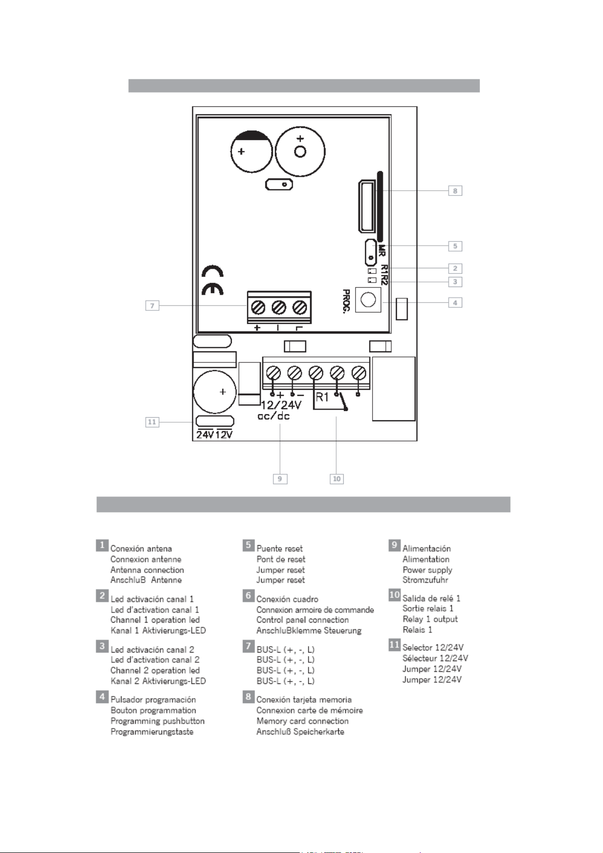
INSTALLATION AND CONNECTIONS (DLX-500)
Attach the rear part of the housing to the wall using the plugs and screws supplied. Pass
the cables through the bottom of the equipment. Connect the power cables to the
terminals marked in the mother board, as indicated. Fix the equipment front to the rear
part using the screws supplied.
OPERATING
The pilot lights are activated every 5 seconds to indicate the correct supply of power to the
equipment.
Upon receiving a code, the receiver checks whether it is in its memory, activating the
corresponding relay. The relay activation mode is selected in either impulse or ON/OFF
using the Imp/Bies jumper (only with relay 2).
PROGRAMMING
MANUAL PROGRAMMING
Press the receiver programming button for 1 sec. and an acoustic signal will be heard. The
receiver will enter standard programming (see table). If the receiver programming button is
held pressed down, the receiver Hill enter special programming, cyclically passing from
one configuration to the next. Once the programming configuration for the transmitter to be
registered has been chosen, send the code to be programmed by pressing the transmitter.
Every time a transmitter is programmed, the receiver will issue an acoustic signal for 0.5
sec. After 10 seconds without programming or pressing the first two transmitter buttons,
the receiver will exit programming mode, issuing two acoustic signals of 1 sec. If upon
programming a transmitter the receiver memory is full, it will issue 7 acoustic signals of
0.5 sec. and exit programming.
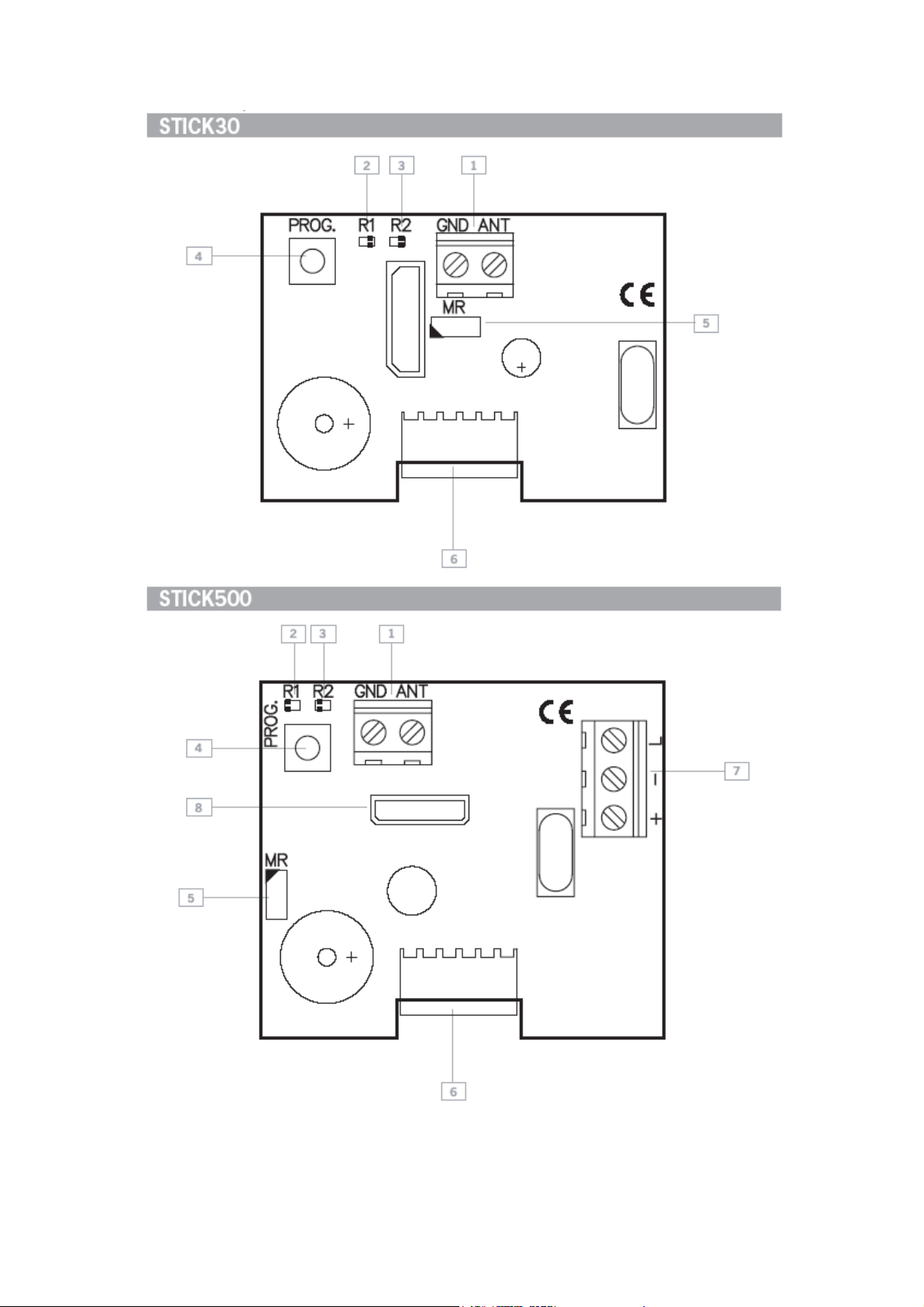
Configuration of transmitter programming in the receiver. Led R1 Led R2
Standard Programming (default option,
the receiver is always configured on pluri-channel)
The relays are activated 1st relay by channel 1
and 2nd relay by channel 2 (3rd relay by channel 1
and 4th relay by channel 2)
Special programming
By pressing any transmitter channel,
relay 1 on the receiver will be activated
By pressing any transmitter channel,
relay 2 on the receiver will be activated
By pressing any transmitter channel, the two relays
will be activated at the same time*
Flashing
ON OFF
OFF ON
ON ON
Flashing
3
Page 4

1248018-GB_v1.0
STICK30/500 – DLX500
• If working in ON/OFF activation mode, relay 1 will act as impulse and relay 2 as
ON/OFF. Therefore, on the first press relay 1 will close and open the contact and
relay 2 will only close. On the second, relay 1 will close and open the contact and
relay 2 will open.
N.B.: Each transmitter can be configured independently on the receiver.
MANUAL PROGRAMMING (DLX)
Press the DLX programming button for 1 sec. and an acoustic signal will be heard. The
DLX will enter standard programming. Every time a proximity element is programmed, the
DLX will issue an acoustic signal for 0.5 sec. After 10 seconds without programming, the
DLX will exit programming mode, issuing two acoustic signals of 1 sec.
TOTAL RESET
In programming mode, the programming button is held down and the “MR” reset jumper
is bridged for 3 secs. The receiver will issue 10 short acoustic warning signals followed by
others at a faster pace to indicate that the operation has been successful. The receiver is
now in programming mode.
After 10 seconds without programming or quickly pressing the programming button, the
receiver will exit programming mode, issuing two acoustic signals of 1 sec.
GROUPS (available on 30-code receivers only)
Receivers can be configured with a group (from 0 to 7) so that there is no interference
when working near each other.
C2- G1
C3- G1
C2- G2
C3- G2
125kHz 868MHz
C2- G1
125kHz
C3- G1
125kHz 868MHz
C2- G2
125kHz
G1
C1- G0
G2
C2- G0
C3- G2
4
Page 5

1248018-GB_v1.0
STICK30/500 – DLX500
C=channel
G=group
N.B. Group 0 enables all groups.
GROUP CONFIGURATION
The configuration can be carried out with the programming tool or by self-programming as
follows.
Self-programming
After the receiver has been totally reset, it will be configured with the group of the first
radio-programmed transmitter by enabling the hands free mode.
Exception: If the receiver has been configured using programming tools, the group may
only be changed with the programming tool.
Operations
On powering the receiver, the led R1 will flash the same number of times as the group
number with which it is configured.
USE OF THE RECEIVER
These receivers are designed for use as remote controls for garage doors. Their use is not
guaranteed for directly activating any other equipment different to that specified.
The manufacturer reserves the right to modify equipment specifications without prior
notice.
WARNINGS
Disconnect the power supply before handing the receiver.
The instructions for using this equipment must remain in the possession of the user.
Hereby, JCM TECHNOLOGIES, S.A., declares that this STICK30, STICK500, DLX500 is
in compliance with the essential requirements and other relevant provisions of Directive
1999/5/EC.
CE DECLARATION OF CONFORMITY
See web www.jcm-tech.com
5
 Loading...