

Page 1
COD. 1247005 / 1.2
ACCESS-1000 / ACCESS-2000
1247005v1-2.indd 1 19/05/2010 11:09:43
Page 2

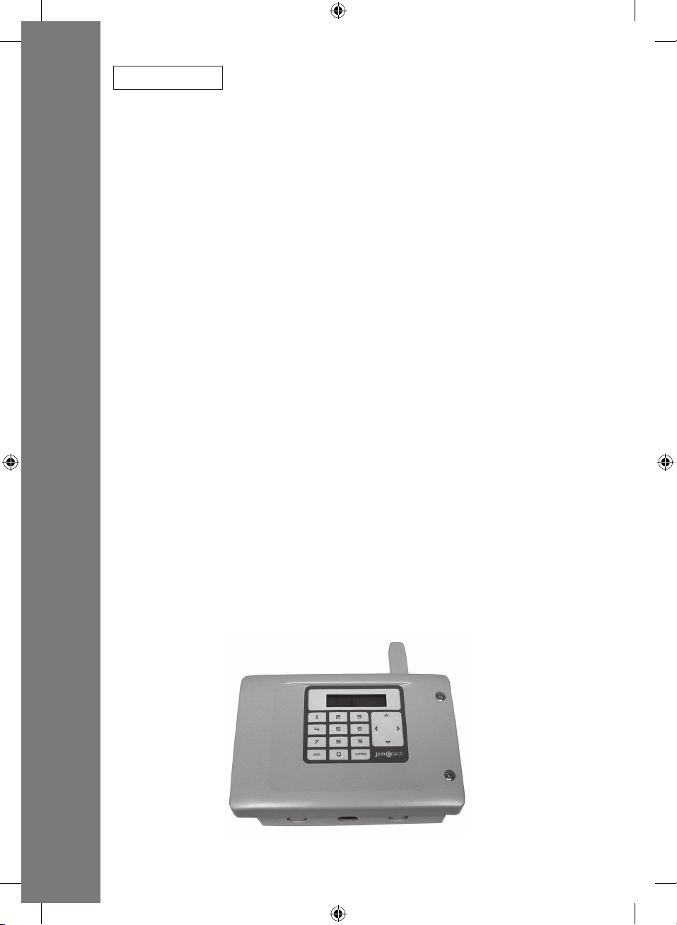
ACCESS-1000 / ACCESS-2000
TECHNICAL FEATURES
ACCESS-1000 / ACCESS-2000
Frequency 868.35MHz
Coding High-security rolling code
Memory 1000 codes (extendible to 2000) / 2000 codes
Events 2000 codes
Number of relays 2 extendible to 4
Anti-panic function Configurable on the 4 relays (assignable only to 1 relay)
Alarm function Only available on proximity equipment with alarm function
Power supply 230Vac / 12Vac/dc
Range at 12V dc 11V –- -19V dc
Range at 12V ac 8 V – 14 V ac
Relay contacts 1A
Standby / Op. Consumption 27mA / 57mA to 230Vac
150mA/550mA to 12V ac/dc
Battery CR 2032 3Vdc (date/time/events)
Access control outlet BUS-L
(Max. 4 readers without external power supply)
Op. temperature -20ºC to +85ºC
Watertightness IP42
Dimensions 170x100x40mm
Box dimensions 220x220x75mm
INSTALLATION AND CONNECTIONS
Fit the rear of the box to the wall using the rawlplugs and screws supplied. Pass the cables through the bottom of the equipment.
Connect the power supply cables to the terminals on the printed circuit, following the indications engraved on the board. Close the
lid on the equipment using the screws supplied.
OPERATING
The name of the controller, the programme version and the date and time will appear on the screen when the equipment is switched on.
Upon receiving a code, the equipment checks whether it is in its memory, enabling the programmed relay/s. The position in the
memory held by the code received and by the relay/s enabling the channel sent by the device are displayed on the screen.
If the device code is not recorded in the memory, the controller will remain motionless and the message “NO” will appear on the
screen.
ENGLISH
MENUS
Press any key to enter the menu and the controller will ask for the password. Enter the 4-digit password using the numeric keys. If
the password is incorrect, the message ERROR 1 will appear on the screen and the equipment will issue a sound signal.
The password is written on an adhesive label on the memory card as standard.
The menus displayed will be:
1- SETUP SYSTEM:Allows for the following to be configured: date/time, relays, channels and language.
2- SETUP CODES: Allows for registrations, cancellations, killpass and discounts to be made
3- SETUP APB: Allows for the anti-passback timer to be configured and reset.
4- EVENTS: Allows for events to be displayed and deleted.
The menu is changed using . To validate each option, press ENTER.
Menu movement key
Menu entry key
ENTER Menu entry or option validation key
ESC Cancellation Key
If no action is made, the equipment will automatically exit programming after 60 seconds and two short sound signals will be given.
19
1247005v1-2.indd 19 19/05/2010 11:09:49
Page 3

21
1- SETUP SYSTEM
Allows for the following to be configured: date/time, relays, channels and language.
1.1 DATE&TIME
1.2 RELAYS
1.3 CHANNELS
1.4 LANGUAGE
1.1 DATE&TIME
This allows for the date and the time to be configured in the controller for correct event management and expiry date management.
Enter the date and time using the numeric keys. If no modifications are to be made, press ESC.
If no action is made, the equipment will automatically exit programming after 60 seconds and two short sound signals are given.
1.2 RELAYS
This allows for the relay enabling timer and anti-panic function on each independent relay to be configured.
Relays Pulsed Biestable Antipanic
1 / 2 / 3 / 4 01-30 seconds Yes 01-15 minutes
If no action is made, the equipment will automatically exit programming after 60 seconds and two short sound signals are given.
1.3 CHANNELS
Allows for a specific relay or relays to be configured for enabling with each channel.
Factory configuration is: Channel 1 enables relay 1, channel 2 enables relay 2, channel 3 enables relay 3 and channel 4 enables
relay 4.
Example: If channel 1 of the transmitter is to be configured to enable relays 1 and 3, numbers 1 and 3, selected using the numeric
keys, must be displayed on the screen.
Every time a numeric key is pressed the required relay is enabled or disabled.
To exit the menu, press ESC.
The configuration chosen for each channel will be programmed into the controller.
If no action is made, the equipment will automatically exit programming after 60 seconds and two short sound signals are given.
1.4 LANGUAGE
This allows for the required language to be selected. This is Spanish by default.
1- ESPAÑOL
2- FRANÇAIS
3- ENGLISH
If no action is made, the equipment will automatically exit programming after 60 seconds and two short sound signals are given.
2- SETUP CODES
Allows for registrations, cancellations, killpass and discounts to be made
2.1 ADD CODES
2.2 DEL CODES
2.3 KILLPASS
2.4 PRE-PAY
2.1 ADD CODES
Allows for individual and sequential registrations to be made
2.1.1 SINGLE
a) Indicating position and code
Enter the position number required and press ENTER. Enter the code number to be programmed and press ENTER. The controller
will issue a sound signal indicating that the operation has been successfully completed.
20
1247005v1-2.indd 20 19/05/2010 11:09:49
Page 4

b) Indicating position
Enter the position number required and press ENTER. Press ENTER so that the controller is ready to receive a code and the
message LEARNING.. will appear on the screen. Once the code has been programmed, the controller automatically jumps to the
next free memory position and is then ready to receive new codes.
To exit the menu, press ESC.
c) Indicating code
Press ENTER and the controller chooses the first free position in its memory. Enter the code number to be programmed and press
ENTER. The controller will issue a sound signal indicating that the operation has been successfully completed.
d) Without indicating the position or code
Press ENTER and the controller chooses the first free position in its memory. Press ENTER so that the controller is ready to
receive a code and the message LEARNING.. will appear on the screen. Once the code has been programmed, the controller
automatically jumps to the next free memory position and is then ready to receive new codes.
To exit the menu, press ESC.
If the code being programmed already exists in the memory, the controller will display ERROR 3 on the screen and will jump to
the programmed memory position, issuing a sound signal.
If the memory position selected is occupied, ERROR 4 will appear on the screen and the controller will jump to the next free
position, issuing a sound signal.
If no action is made, the equipment will automatically exit programming after 60 seconds and two short sound signals are given.
2.1.2 RANGE
This allows for sequential registrations to be made, selecting the initial memory position, initial code and number of transmitters
to be programmed.
a) Indicating position, amount and code
Enter the initial position number required and press ENTER. Enter the number of codes to be programmed and press ENTER.
Enter the initial code number to be programmed and press ENTER. When ENTER is pressed, the controller checks whether the
memory space indicated is available and makes the appropriate registrations, showing the sequential codes being programmed
on the screen.
To exit the menu, press ESC.
ENGLISH
b) Indicating position and amount
Enter the position number required and press ENTER. Enter the number of codes to be programmed and press ENTER. When
ENTER is pressed again, the controller checks whether the memory space indicated is available and remains ready to receive a
code. The message LEARNING.. will appear on the screen. Once the first code has been programmed, the controller automatically makes the appropriate registrations, showing the sequential codes being programmed on the screen.
To exit the menu, press ESC.
c) Indicating amount and code
Press ENTER and the controller chooses the first free position in its memory. Enter the number of codes to be programmed
and press ENTER. Enter the code number to be programmed and press ENTER. When ENTER is pressed, the controller checks
whether the memory space indicated is available and makes the appropriate registrations, showing the sequential codes being
programmed on the screen.
To exit the menu, press ESC.
d) Indicating the amount only
Press ENTER and the controller chooses the first free position in its memory. Enter the number of codes to be programmed and
press ENTER. When ENTER is pressed again, the controller checks whether the memory space indicated is available and remains
ready to receive a code. The message LEARNING.. will appear on the screen. Once the first code has been programmed, the
controller automatically makes the appropriate registrations, showing the sequential codes being programmed on the screen.
To exit the menu, press ESC.
Warning: According to the number of registrations to be made, this operation may take several minutes.
If there is no space available, the controller will show ERROR 6 on the screen and will issue a sound signal. No code will be
programmed.
21
1247005v1-2.indd 21 19/05/2010 11:09:49
Page 5

23
If the code being programmed already exists in the memory, the controller will display ERROR 3 and the programmed memory
position on the screen, issuing a sound signal.
If the memory position selected is occupied, ERROR 4 will appear on the screen and the controller will jump to the next free
position, issuing a sound signal.
If no action is made, the equipment will automatically exit programming after 60 seconds and two short sound signals are
given.
2.2 DEL CODES
This allows for individual or sequential cancellations or a total reset to be made.
2.2.1 Per position (POSITION)
Select the memory position to be deleted using the numeric keys and press ENTER. The controller will issue a series of short
sound signals to indicate that the operation is being carried out. OK will appear on the screen.
2.2.2 Per code (CODE)
Select the code to be deleted using the numeric keys and press ENTER. The controller will issue a series of short sound signals
to indicate that the operation is being carried out. OK will appear on the screen.
2.2.3 Sequential cancellations (RANGE)
Select the memory position to be deleted using the numeric keys and press ENTER. Select the number of codes to be deleted.
Press ENTER, the controller will issue a series of short sound signals to indicate that the operation is being carried out and the
message OPERATING will appear on the screen. Once the operation is complete, OK will appear on the screen.
2.2.4 Total reset (DELETE ALL)
The message HOLD ENTER will appear on the screen and the equipment will issue a series of short warning sounds. Keep
ENTER pressed down and the equipment will issue a series of intermittent sounds. OK will appear on the screen. If ESC is pressed
during warning status, reset is cancelled.
If the code or position to be deleted is not programmed, the controller will show ERROR 2 on the screen and will return to the
menu.
If no action is made, the equipment will automatically exit programming after 60 seconds and two short sound signals are given.
2.3 KILLPASS
This allows for individual or sequential codes to be disabled (the memory position remains occupied).
On receiving the disabled code, no output is activated on the controller and the message “NO” is shown on the screen. If it is a
proximity element, it is destroyed and becomes unusable.
2.3.1 Per position (POSITION)
Select the memory position to be disabled using the numeric keys and press ENTER. The controller will issue a sound signal to
indicate that the operation is being carried out. OK will appear on the screen.
2.3.2 Per code (POR CODIGO)
Select the code to be disabled using the numeric keys and press ENTER. The controller will issue a sound signal to indicate that
the operation is being carried out. OK will appear on the screen.
2.3.3 RANGE
Select the memory position to be disabled using the numeric keys and press ENTER. Select the number of codes to be disabled.
Press ENTER, the controller will issue a sound signal to indicate that the operation is being carried out and the message OPERATING will appear on the screen. Once the operation is complete, OK will appear on the screen.
To enable a code on a disabled transmitter, enter the registration menu and run an individual registration without indicating the
position or the code. The controller will show ERROR 3 on the screen and will jump to the programmed memory position, issuing
a sound signal. Press the transmitter again and it will become enabled.
If the code or position to be deleted is not programmed, the controller will show ERROR 2 on the screen and will return to
the menu.
If no action is made, the equipment will automatically exit programming after 60 seconds and two short sound signals are given.
22
1247005v1-2.indd 22 19/05/2010 11:09:50
Page 6

2.4 PRE-PAY
This allows for units on a proximity element with pre-payment function to be discounted (maximum 65535 units).
Pre-payment Function
In the pre-payment function, users have a proximity element allocated, following payment (of a certain number of units), using
the Assistant programming tool.
The units to be discounted every time users pass their proximity element in front of a reader are programmed into the controller.
Each reader can discount a different number of units. Users can use the proximity element while it is in credit. When the credit
is used up it can be recharged.
On receiving a code with the pre-payment function programmed, the controller activates the corresponding output and discounts
the units previously allocated to that channel (one unit is discounted by default). If more units are to be discounted than those
available, the controller will remain motionless and the message “NO CREDIT” will appear on the screen.
Configuration
The proximity elements with the pre-payment function must be registered in the controller using the numeric keys to enter the
PRE-PAYMENT PIN number instead of the code in the registration menu. The factory-issued PRE-PAYMENT PIN number is the
same for all devices (000000). Use the Assistant programming tool to modify this number individually.
Enter the required channel and press ENTER. Enter the number to be discounted (maximum 4 digits) and press ENTER. The
controller will issue a sound signal to indicate that the operation is being carried out. OK will appear on the screen.
If no action is made, the equipment will automatically exit programming after 60 seconds and two short sound signals are
given.
3- SETUP APB
Allows for the anti-passback timer to be configured and reset.
3.1 APB CONF
Select the operating mode and press ENTER.
MODE Function
MODE 0 Anti-passback disabled
MODE 1 Anti-passback for single-channel devices and a single door (entry and exit)
MODE 2 Anti-passback for dual-channel devices and two doors (one entry and another exit)
Select the anti-passback enabling time and press ENTER.
TIME Function
0 Absolute anti-passback
1-60 minutes Anti-timeback
3.2 RESET APB
Press ENTER and the controller will reset the anti-passback. Once reset has been completed, the anti-passback is initialised and
access is allowed in either direction (entry or exit), thus re-enabling the anti-passback individually for each user.
ENGLISH
In the event of the controller power supply being cut off, the anti-passback is automatically reset.
If a user accesses for a second consecutive time in the same direction, the controller will remain motionless and the message “NO
APB” will appear on the screen.
If no action is made, the equipment will automatically exit programming after 60 seconds and two short sound signals are given.
23
1247005v1-2.indd 23 19/05/2010 11:09:50
Page 7

25
4- EVENTS
Allows for events to be displayed and deleted.
4.1 SHOW EVENTS
This shows the date and time of the event, the type of event and the code and number of the last event. Using , all of the
events can be displayed, moving around by number of events.
# DATE TIME...... ..
TYPE OF EVENT CODE > EVENT No..
Display Type of event
C00 No event
C01 Channel 1 reception
C02 Channel 2 reception
C03 Channel 3 reception
C04 Channel 4 reception
C08 Attempt at radio programming
C09 Anti-panic enabled
C10 Alarm function enabled
C11 Code already entered or exited
C12 Code not programmed or disabled
To exit the menu, press ESC.
4.2 DELETE ALL
Press ENTER and the controller will totally reset the events card and the message OPERATING will appear on the screen. Once the
operation is complete, OK will appear on the screen.
If no action is made, the equipment will automatically exit programming after 60 seconds and two short sound signals are given.
ALARM FUNCTION
This function is only configurable using the Assistant programming tool and is only available on proximity elements where the alarm
function is implemented.
Allows for the enabling of a different relay to that programmed by default, reading the device a certain number of consecutive times
in a maximum time of 5 seconds between each reading.
Example: the proximity element enables relay 1 by default and with the alarm function it will enable relay 3 on reading the device
4 consecutive times.
MESSAGES
Display Type of message
NO This appears when a code that is not programmed or that is disabled in the controller is enabled
DATE This appears when a proximity element is used outside its validity period.
NO CREDIT This appears when a proximity element is used when no credit is available.
NO APB This appears when the anti-passback does not allow access
24
1247005v1-2.indd 24 19/05/2010 11:09:50
Page 8

ERRORS
Display Type of error
ERROR 1 Incorrect password
ERROR 2 Code not found or memory position free
ERROR 3 Repeated code: shows the memory position of the programmed code. A sound signal is issued.
ERROR 4 Position occupied: jumps to the first free position. A sound signal is issued.
ERROR 5 Data outside range
ERROR 6 Lack of space available in memory for the range selected or memory full. A sound signal is issued.
ERROR 7 Memory error: memory card not inserted, erroneous or with incorrect format (from other equipment).
ERROR 8 Events error: events card incorrect or with incorrect format (from other equipment).
OPTIONAL ANTI-PASSBACK CARD OPERATIONS
Card connections
Connect the anti-passback card to the controller, disconnecting the power supply.
1
1
2
3
4
5
Operations
The Anti-passback provides access and exit control, preventing a user from accessing consecutively in the same direction. The user
must access only once in each direction (entry and exit).
The Anti-timeback is a timed anti-passback and allows for access twice consecutively in the same direction after the selected time.
Operations with transmitters
Magnetic sensors must be used for card operations with transmitters to be able to distinguish the entry and exit of vehicles to and
from an installation. Therefore, the card includes three terminals (presence contact normally open for entry and exit and common)
for the connection of sensors.
Warning: to validate entry access, one must be located on the entry loop and press the transmitter at the same time. To validate
exit access, one must be located on the exit loop and press the transmitter at the same time.
Operations with access control devices
In this case, magnetic sensor connection is optional (where not used, leave the terminals unconnected).
Detection indication Leds
2
EXIT presence contact
3
ENTRY presence contact
4
Common
5
Connect card to controller
ENGLISH
Modes
If you work at MODE 1, the configuration will be the following: channel 1 for entry, channel 2 for exit. The channels 3 and 4 will be
free and they will not be controlled by the anti-passback.
If you work at MODE 2, the configuration will be the following: channel 1 et 3 for entry, channel 2 et 4 for exit.
USE OF THE CONTROLLER
These equipments are designed for the remote control of garage doors, to send the activation commands to control panels and to
activate/deactivate alarm systems. Its use is not guaranteed for directly activating equipments other than those specified.
The manufacturer reserves the right to modify equipment specifications without prior notice.
25
1247005v1-2.indd 25 19/05/2010 11:09:50
Page 9

IMPORTANT ANNEX
Disconnect the power supply before handing the equipment.
In compliance with the European Directive low-voltage electrical equipment, we hereby inform users of the following requirements:
• For equipments which are permanently connected, an easily accessible circuit-breaker device must be built into the wiring system.
• This equipment must always be installed in a vertical position and firmly fixed to the structure of the building.
• This equipment must only be handled by a specialised installer, by his maintenance staff or by a duly trained operator.
• The instruction manual for this equipment must always remain in the possession of the user.
• Terminals of maximum section 3,8mm
• Use time delayed fuses.
2
must be used for the power supply connections.
EC DECLARATION OF CONFORMITY
The manufacturer
JCM TECHNOLOGIES, S.A.
C/Bisbe Morgades, 46 Baixos
08500 VIC – Barcelona
SPAIN
declares herewith that the product designated below complies with the relevant fundamental requirements as per Article 3 of the
R&TTE Directive 1999/5/EG, insofar as the product is used correctly, and that the following standards apply:
Product: Controller 868,35MHz
Manufactured by: JCM TECHNOLOGIES, S.A.
Trade mark: JCM
Type: ACCESS-1000 / ACCESS-2000
Environment of use: Residential, commercial and light industry
Standards:
• Telecommunication EN 300 220-1 v1.3.1 (2000-09), EN 300 200-3 v1.1.1 (2000-09)
• Electromagnetic Compatibility EN 301 489-3 v1.3.1 (2001-11), EN 301 489-1 v1.3.1 (2001-09)
• Low Voltage EN 60730-1 (2000)
Vic, 20/12/04
JUAN CAPDEVILA MAS
General manager
A, B, CH, D, E, F, GB, I, IRL, IS, L, NL, P
26
1247005v1-2.indd 26 19/05/2010 11:09:50
Page 10

ACCESS-1000 / ACCESS-2000
1247005v1-2.indd 60 19/05/2010 11:09:54
 Loading...