

Page 1
J C F A U D I O
L a t t e
LATTE USER MANUAL
110 48 Cam a ril lo St. #3 N. H oll ywo od, CA 91 602
JCF AUDIO, LLC.
11048 CAMARILLO ST.
#3
NORTH HOLLYWOOD, CA 91602
WWW.JCFAUDIO.COM
•
w ww. jcf aud io. c om
Page 2

JCF Audio
Latte
Safety Information
Do not repair, modify, service this device except in the manner in which it is described in this manual. Doing so can
endanger the user and others as well as void the warranty.
Fuses should be replaced with the exact values stated in the manual.
To comply with most electrical wiring codes, the Latte is equipped with a 3 wire IEC style connector, the grounding
pin of which is connected to the chassis. JCF Audio, LLC accepts no responsibility for legal actions or for direct, incidental, or consequential damages that may result from improper installation, configuration, or use of the Latte.
Overview
The Latte is comprised of two main sections:
1. A high-resolution stereo audio analog to digital converter
2. A section that serves as a stereo digital to analog converter or two channels of microphone pre-amplification or two
channels of reproduction amplifiers specifically for low impedance tape machine heads. This section will be called
the "DMT" section for the rest of this manual.
These two sections can operate completely independently from one another or together in a number of ways that will
be discussed in this manual.
Under normal operation the A/D section begins at the line inputs and ends at the AES compatible outputs (XLR balanced or TOSLINK).
Under normal operation the DMT section begins at the AES compatible inputs (XLR balanced or TOSLINK) and ends
at the analog outputs (BAL out or AUX out)
Feature list
Two AES compatible transformer coupled outputs (mono configurable)
•
Two AES compatible transformer coupled inputs for synchronization reference and data input for both sections -
•
front panel switch selectable
Line level +4 dBu analog outputs - Cinemag Transformer coupled, +27.5dBu Max. output level into 600 Ω (+28 dBu
•
hi-z)
J CF Au d io" L att e
1
Page 3
JCF Audio
Concurrent jumper configurable auxiliary output, +22.5 dBu Max. output level - line amp, +6.7dBu Max. output
•
level - preamp
Completely user configurable line input block (Actively balanced, unbalanced)
•
Multi-turn trimmers for precise control of A/D input level
•
Multi-turn trimmers for precise control of A/D offset calibration
•
Stylish blue D/A receiver unlocked indicator
•
Power supply configurable for 120vac / 60Hz or 240vac / 50Hz operation
•
Very low leakage, caged flat pack power transformers for high isolation and low field
•
Unique power supply isolation used throughout
•
>.01 ms total latency A/D section @ 192k
•
Cascade function allows easy digital capture of D/A, Mic pre, or Tape playback
•
Four position selectable pad to optimize drive of very high quality Cinemag mic input transformer
•
Independently selectable phantom power
•
2ch. Optical I/O
•
Flexible and independent clocking arrangement
•
0 dBu is referenced to 0.775 vrms for this manual
J CF Au d io" L att e
2
Page 4

JCF Audio
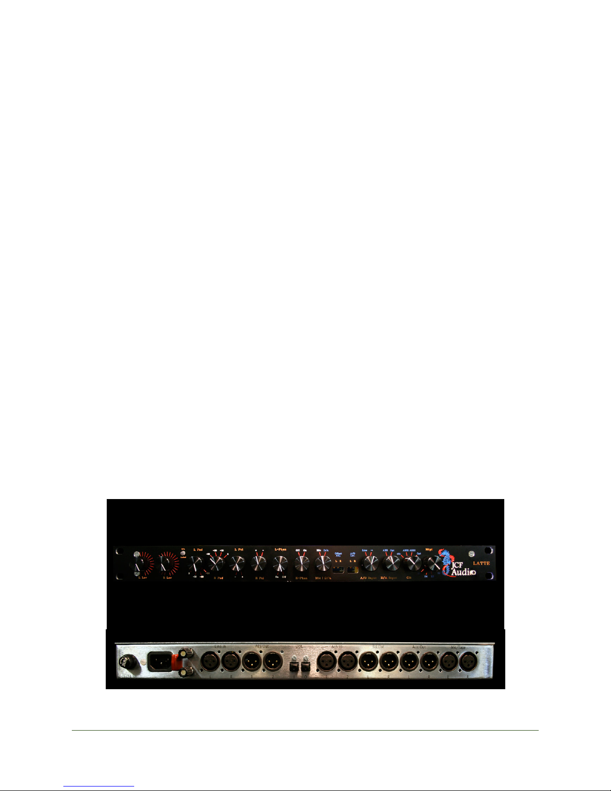
Front Panel Controls
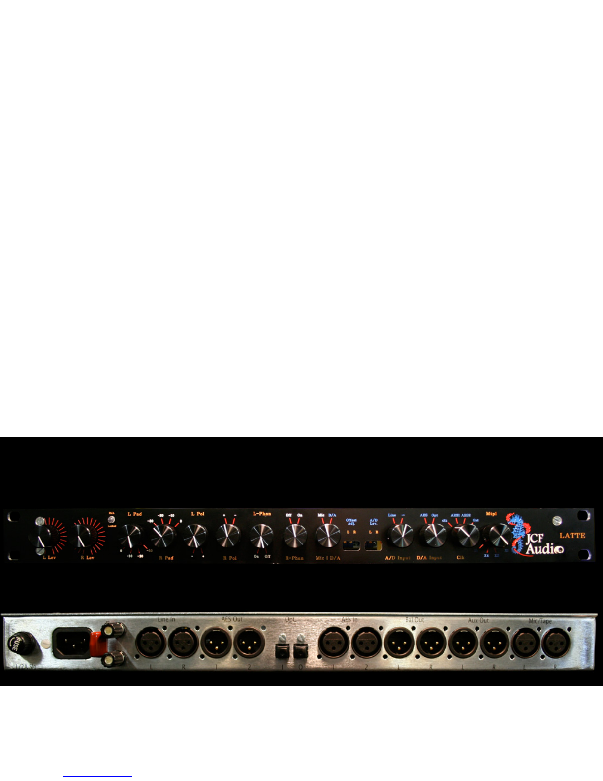
The numerous front panel controls are arranged to be as user friendly as possible. DMT functions are towards the
left side of the front panel and the A/D functions are towards the right.
L Lev, R Lev - This is the attenuator between the preamp and line amp blocks in the DMT section of the device. It
will affect the output level of the BAL outputs and AUX outputs (in high level mode) This control should also be used
as a vernier adjustment between the pad values when using the device as a mic pre. The fully clock wise position
provides no attenuation and the fully counter-clockwise position provides approximately 13 db of attenuation.
D/A Locked - This LED indicates that the input signal from either the AES 1 jack or the TOSLINK input is valid
depending on which signal is selected from the D/A input switch. This LED does NOT indicate anything about the
status of the AES 2 signal.
L Pad, R Pad - These switches attenuate the signal coming in from the MIC/TAPE jacks on the rear. 0 (no attenua-
tion), -10db, -20db, -30db are selectable. When using the devices as Tape machine electronics both of these switches
should be set to 0 or no attenuation. The pads have no effect when using the DMT section as a D/A; however there
will be the residual resistive load of the pad on the mic line regardless of whether or not the signal is used.
L Pol, R Pol - The switches change the polarity of the signal from the MIC/Tape jacks on the rear. They have no
effect when using the DMT section as a D/A.
L Phan, R Phan - These switches engage a common mode voltage of approx. 37vdc on the “MIC/TAPE” input
jacks for purposes of phantom powering condenser microphones. (the source resistance of the phantom power has
been adjusted to give a comparable amount of power to microphones designed to work from 48 volts)
Phantom should not be engaged when using this section as TAPE machine electronics. No harm will come to the
connected tape head provided the cables are wired properly, but it is a very poor idea to allow a voltage near your
tapes in this manner.
MIC / D/A - This switch decides whether the D/A or the MIC / Tape circuit (mic/tape input, pad, phantom, polar-
ity) feeds the DMT section of the unit.
A/D Offset L,R - A multi-turn trimmer controls the amount of DC offset in the A/D circuit which is accessible
with a "tweaker" or small screwdriver through the front of the unit. A digital meter with enough resolution should be
connected to the LATTE AES output in order to adjust this control properly. This control should not be adjusted unless the unit has been on for at least an hour and has temperature stabilized.
A/D Lev - A multi-turn trimmer controls the amount of signal input to the A/D circuit. This control is accessible
with a "tweaker" or small screwdriver through the front of the unit. This "pot" will fully attenuate the input signal if
adjusted to do so. Fully clockwise will adjust the the unit such that a +4 dBu signal at the line input will yield ~-10.5
dBFS digital level (with the line input configured as it is in shipping).
A/D input - Also referred to as “Cascade”. This switch controls the input signal to the A/D section. In line the line
input will feed the A/D attenuator. In -> mode, the output of the DMT section will feed the A/D input. Care must
J CF Au d io" L att e
3
Page 5

JCF Audio
be taken in this mode to not connect the output of the A/D in a direct or indirect fashion back to the D/A such that a
feedback loop exists. The extremely high levels and spikes generated by doing this can damage the A/D converter
section.
D/A input - This switch controls the input signal to the first AES receiver. AES selects the signal from the AES 1
input and Opt. selects the input from the TOSLINK jack. Whichever signal is selected is passed on to the D/A converter section in all modes of operation.
CLK and Multiple - This switch selects the clock source for the AES compatible output section of the A/D or
sample rate converter as follows:
• All operation of the A/D section of the Latte at 44.1kHz and multiples thereof require external clocking.
• 48k refers to the internal clock which will run the AES compatible outputs @ 48k or multiples thereof (depending
upon the setting of the multiple switch).
• The AES 1 setting will derive the clock source for the AES compatible outputs from the AES 1 input. In this setting
the recovered sample rate will be the sample rate of interest and the setting of the multiple switch has no bearing. In
this mode the D/A section and the A/D section will run in sync with one another.
• The AES 2 setting will derive the clock source for the AES compatible outputs from the AES 2 input. In this setting
the recovered sample rate will be the sample rate of interest and the setting of the multiple switch will have no bearing.
• The Opt. setting will derive the clock source for the AES compatible outputs from the Opt. input. In this setting the
recovered sample rate will be the sample rate of interest and the setting of the multiple switch will have no bearing.
The Multiply switch will select X1-48k, X2-96k, or X4-192k only if the CLK source is the internal 48k. With all other
•
sync sources, the setting of this switch is ignored.
Rear Panel
MIC/Tape - These inputs are meant for low impedance microphone signals (~200 Ω) or low impedance tape heads
(between 2µH and 10µH). The input Impedance at this point is dependent upon the adjustment of the input loading
pot and actuation of the pad
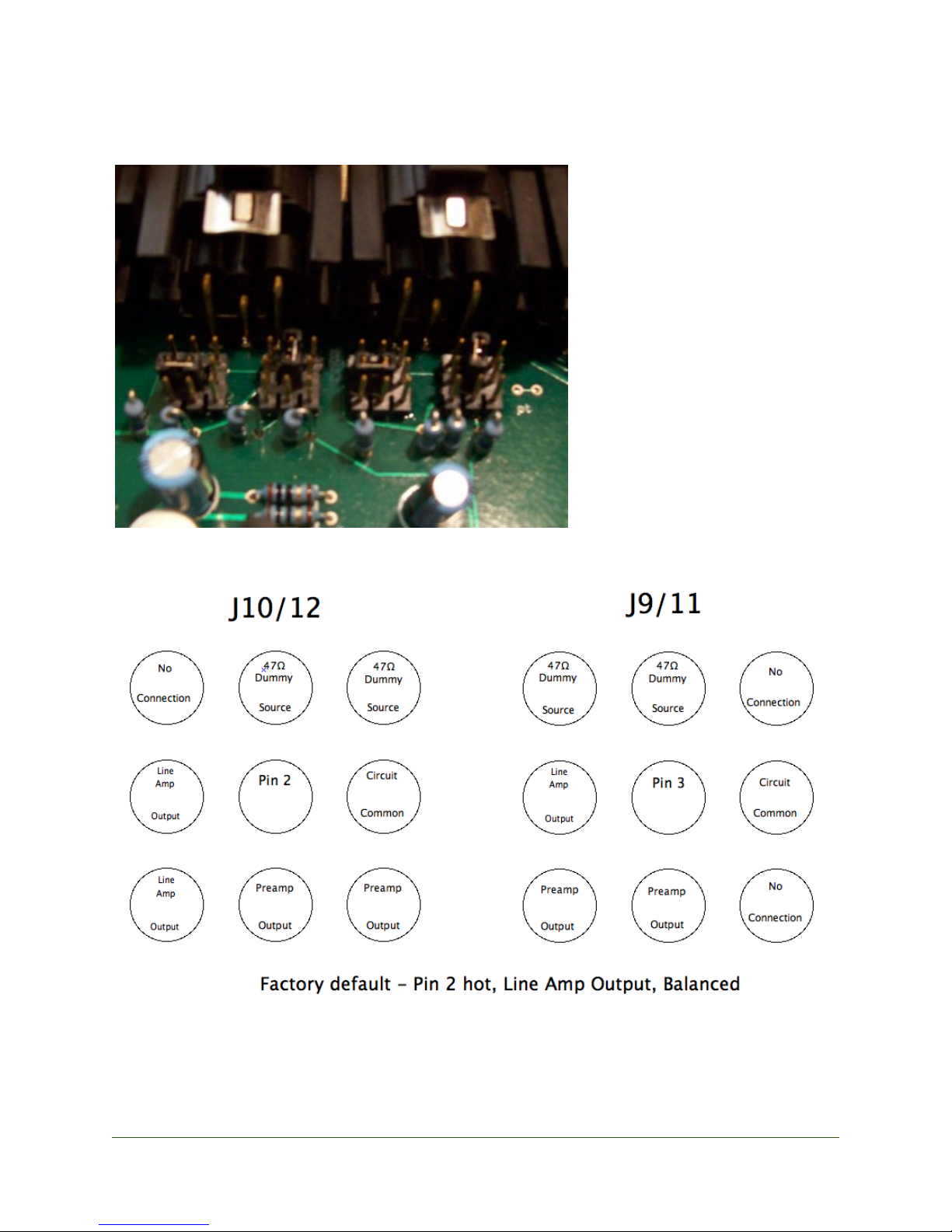
AUX outputs - These are the jumper configurable outputs of the DMT section of the unit. They can utilize any
combination of the following features
Pin 2 or 3 hot
•
Balanced or unbalanced operation
•
Line level output or pre-attenuator low level preamp output
•
See pictures below:
J CF Au d io" L att e
4
Page 6
JCF Audio
At Latte rear, left:
J CF Au d io" L att e
5
Page 7

JCF Audio
The output impedance of this point is 47 Ω in all unbalanced configurations. The output impedance is ~94 Ω in bal-
anced configurations (47 Ω per leg). These conditions are for both preamp and line amp outputs. The 4 transistor
line amplifier employed here has a great deal of drive and will have no problem sounding good into loads as low as
600 Ω. The preamp output will not drive appreciable loads with any measure of sonic merit. The load when using
this port as a preamp output should not be below 5k Ω and preferably higher. Cable runs from this point should be
sensible as well.
BAL outputs - These outputs are the transformer coupled main outputs of the DMT section of the unit. The output
impedance is ~75 ohms floating. The unit will start to sound (and measure) poorly with a load lower than 500 Ω.
AES inputs - These inputs are transformer coupled, 110 ohm balanced. The inputs will receive AES compatible
streams from a variety of sources. AES compatible inputs are single wire only.
Note: Since this input is transformer coupled and sensitive enough, use of a simple adapter or custom-wired cable
may be employed to connect this input to a “consumer” or “S/PDIF” output in most cases. This style connection will
usually not terminate the line correctly, so cable runs should be kept to a minimum to avoid interface related time-
base problems.
Opt. I/O - These jacks (commonly known as TOSLINK) will work up to 192k. The Optical output will only transmit
data from the left channel in mono mode. APF cable length should not exceed 16ft.
AES outputs - These outputs are transformer coupled 110 ohm sources. They will drive any reasonable amount of
110 ohm terminated AES cabling effectively. Operation at many hundreds or thousands of feet is not recommended.
These outputs can be operated in dual mono mode with the change of a jumper. (See jumper section)
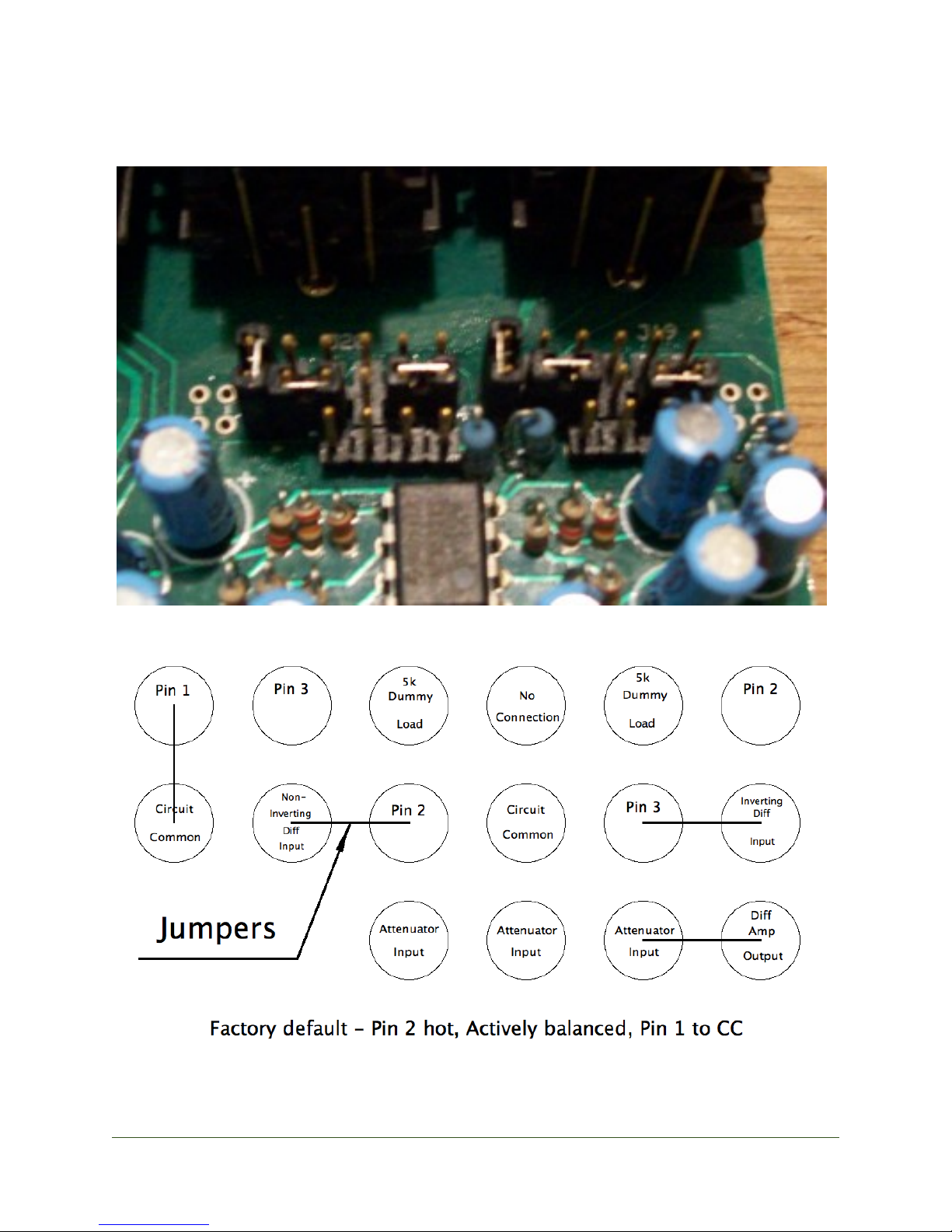
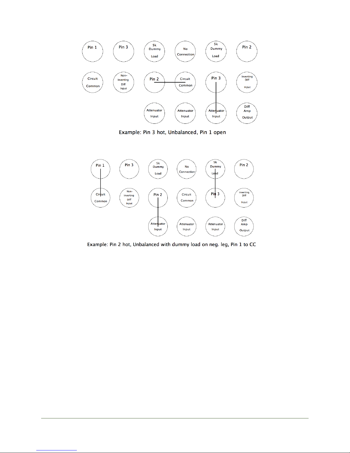
Line Inputs - These inputs are jumper configurable to utilize any combination of the following features
Pin 1 lift
•
Pin 2 or 3 hot
•
Actively balanced or unbalanced operation (with or without dummy load on negative leg)
•
Dummy loading can assist only with specific kinds of actively balanced outputs feeding an unbalanced input to
prevent and the output devices amplifier from driving directly into ground. This may not be useful in all cases.
See below pictures and diagrams for defaults and examples:
J CF Au d io" L att e
6
Page 8
JCF Audio
At Latte rear, right:
J CF Au d io" L att e
7
Page 9
JCF Audio
Binding Posts - Ccom, Ch.
Chassis and Circuit Common. If you don’t know what they’re for, don’t change them or
the installed capacitor between them.
J CF Au d io" L att e
8
Page 10
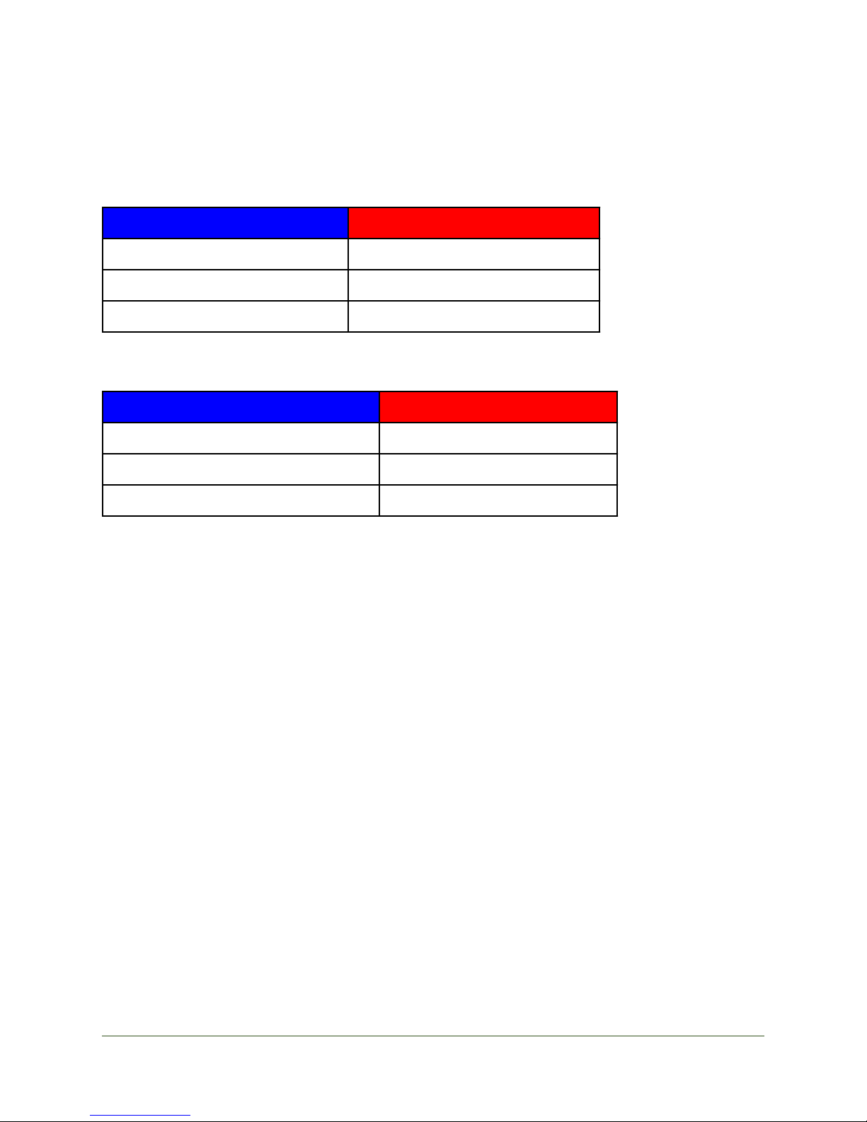
MIN
MAX
L Lev, R Lev fully counterclockwise
L Lev, R Lev fully clockwise
0dBfs yields +13dBu at “Bal” outputs
0dBfs yields +26.4dBu at “Bal” outputs
-9dBfs yields +4dBu at “Bal” outputs
-22.4dBfs yields +4dBu at “Bal” outputs
MIN
MAX
A/D Lev L,R fully counterclockwise
A/D Lev L,R fully clockwise
any level yields ~-94 dBfs at AES outputs
+14dBu yields 0dBfs at AES outputs
any level yields ~-94 dBfs at AES outputs
+4dBu yields -10dBfs at AES outputs
JCF Audio
Specifications
D/A Calibration Range
A/D Calibration Range
A/D Latency (calculated, not from empirical test)
44100 output 0.812 ms
48000 output 0.754 ms
88200 output 0.450 ms
96000 output 0.420 ms
176400 output 0.268 ms
192000 output 0.004 ms
D/A Latency (calculated, not from empirical test)
44100 0.657 ms
48000 0.604 ms
88200 0.328 ms
96000 0.302 ms
176400 0.164 ms
192000 0.151 ms
Emphasis / De-emphasis is not supported anywhere in the Latte.
Power Consumption:
<25 Watts under all conditions
J CF Au d io" L att e
9
Page 11

JCF Audio
Microphone Preamp
EIN: -118dBu (with 150 ohm source @ 60 db of gain)
Max Gain: 62 db (@ “Bal” outputs)
Min Gain: 19 db (@ “Bal” outputs)
Frequency Response: 10 Hz to 80 kHz +/- 1 dB (200 Ω source)
A/D D/A as a system THD+N figures
All values with factory passive A/D filter
! (Unity level, 48kHz, 400 to 18k BW, 1kHz tone)
" -20dBFS to 0 out: 0.03%
" -10dBFS to +10 out: 0.008%
" -30dBFS to -10 out: 0.1%
" -35dBFS to -10 out: 0.15%!
! (Unity level, 192kHz, 400 to 18k BW, 1kHz tone)
" -20dBFS to 0 out: 0.03%
" -10dBFS to +10 out: 0.03%
" -30dBFS to -10 out: 0.08%
" -35dBFS to -10 out: 0.15%
! (Unity level, 192kHz, 10 to 200k BW, 1kHz tone)
" -20dBFS to 0 out: 0.057%
" -10dBFS to +10 out: 0.035%
" -30dBFS to -10 out: 0.18%
" -35dBFS to -10 out: 0.3%
J CF Au d io" L att e
10
Page 12

JCF Audio
A/D D/A as a system - Frequency Response
20Hz to 17kHz +/-1dB (-1.3 dB @ 20kHz)
DAC residual noise (no BW limiting)
192k: -57dBu
96k: -55dBu
48k: -28dBu (mostly noise around 40kHz)
DAC residual noise (22k upper BW limit, “Lev” fully clockwise)
192k: -71dBu
96k: -70dBu
48k: -65dBu
Shipping weight
14lbs.
Max Dimensions
L: 10.31”
W: 19”
H: 1.74”
Fuses: 2x 500ma, 5X20mm on board (HV and LV - one each for draw protetion)
! 1x 1A or less, 3AG (for mains/chassis short safety)
J CF Au d io" L att e
11
Page 13
JCF Audio
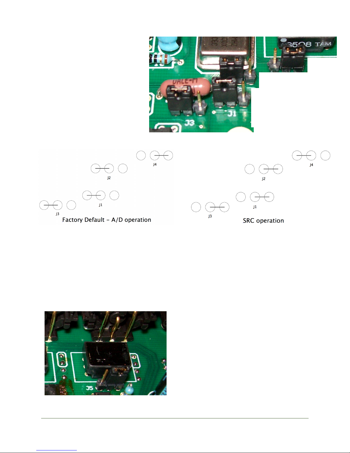
Jumper Settings
J1-4 - Adjust for Digital Sample
Rate Conversion function as shown
in picture
Ships configured for A/D operation
as shown below:
J5 - Dual Wire "mono" mode operation of AES compatible output
Ships in stereo mode as pictured below:
J CF Au d io" L att e
12
Page 14
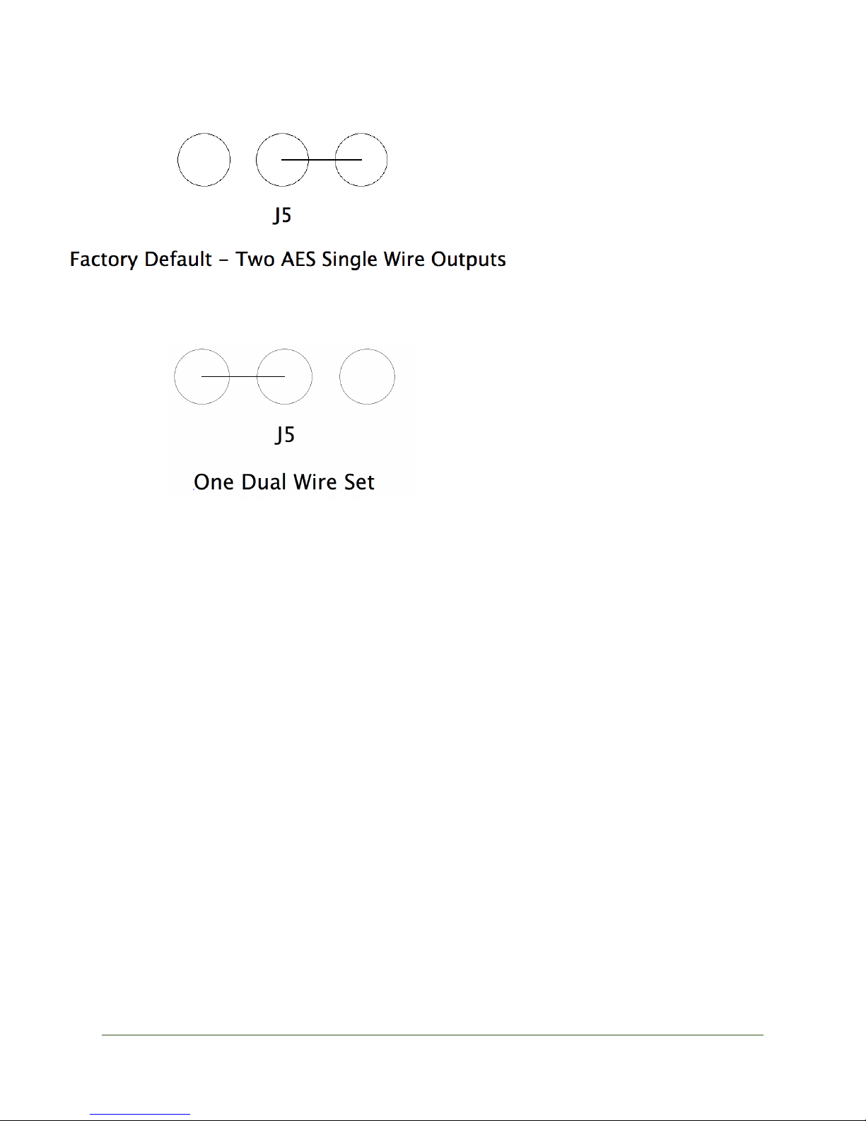
JCF Audio
J6 - Cascade Safety Defeat
Ships in the protected position which prevents the cascade operation while the DMT section is
set to D/A. This function is helpful in preventing feedback loops as in most cases the AES
compatible outputs are connected to a device which will pass through directly to it’s output and
thence to the AES 1 input on the Latte. If the Latte is in cascade at this point, the analog output
of the DMT section would then pass back to the input of the A/D and make a loop. Ouch!
Change at your own risk. (Serial #00020-00024 inclusive do not have this jumper)
J7-8 - Ground lift for AES compatible inputs
Ships in the unlifted position.
Remove jumper for lift.
A capacitor can be installed across the terminals as well.
Unless you really know what you're doing, don't change this.
J CF Au d io" L att e
13
Page 15
JCF Audio
J9-12 - Aux. output setup
See picture and diagrams in the “Rear Panel” section of this manual.
Ships in high level, Pin 2 hot, Balanced mode.
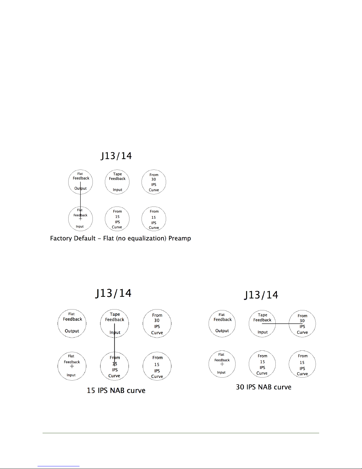
J13-14 - Tape mode setup
Ships setup for flat (no e.q.) preamp operation (for microphones, and D/A) as shown below:
J CF Au d io" L att e
14
Page 16

JCF Audio
J15-18 - Future use.
For active filter plugin module
Do not change.
J19-20 Line Input setup
See pictures and diagrams in the “Rear Panel” section of this manual.
Ships in Pin 2 hot, Balanced, Differential input
Tape Curve Adjustments
There are eight small blue pot adjustments for the NAB tape equalization adjustments - four per
channel. These pots are located beneath the top cover near the left front of the unit.
Two per channel are for 15 IPS and two are for 30 IPS
HSHF - 30ips high frequency eq adjustment
HSLF - 30ips low frequency eq adjustment
LSHF - 15ips high frequency eq adjustment
LSLF - 15ips low frequency eq adjustment
Mic / Tape Load Adjustment
The secondary of the mic input transformer in the DMT section may be resistively loaded by
adjusting the two blue pots located near or under the ribbon cables at the front left of the unit.
The head / mic load may be adjusted in order to achieve desired performance from tape heads
with respect to high frequency extension. And may also serve to load down microphones. Mic
loading is highly discouraged.
Digital Sample Rate Conversion
The Latte may optionally be configured to serve as a standalone digital sample rate converter.
This feature was added to make even greater use of the wonderful sample rate converter chip
used in the Latte. Four jumpers must be changed in order to enter this mode. Under these conditions the Latte A/D will be disabled. AES compatible streams entering on AES 2 will be presented to the sample rate converter and will exit the unit at the new sample rate under the same
conditions that would apply for AES compatible outputs in A/D operation. Remember what-
J CF Au d io" L att e
15
Page 17

JCF Audio
ever signal is present on AES 1 (or Opt if the D/A input switch is set as such) will go to the D/A
device. Obviously if the DMT section is being used in Mic or Tape mode, this is irrelevant.
For example:
AES input stream @ 176.4kHz enters on AES 2
CLK sw: 48k
D/A input: doesn't matter
Multiple sw: x2
new AES output stream available on AES 1 and AES 2 outputs (in stereo mode) @ 96kHz
Another example:
AES input stream @ 44.1kHz enters on AES 2
AES clock reference stream @ 88.2kHz enters on Opt in.
CLK sw: AES 1
D/A input: Opt
Multiple sw: doesn't matter
new AES output stream available on AES 1 an AES 2 outputs (in stereo mode) @ 88.2kHz
Notes
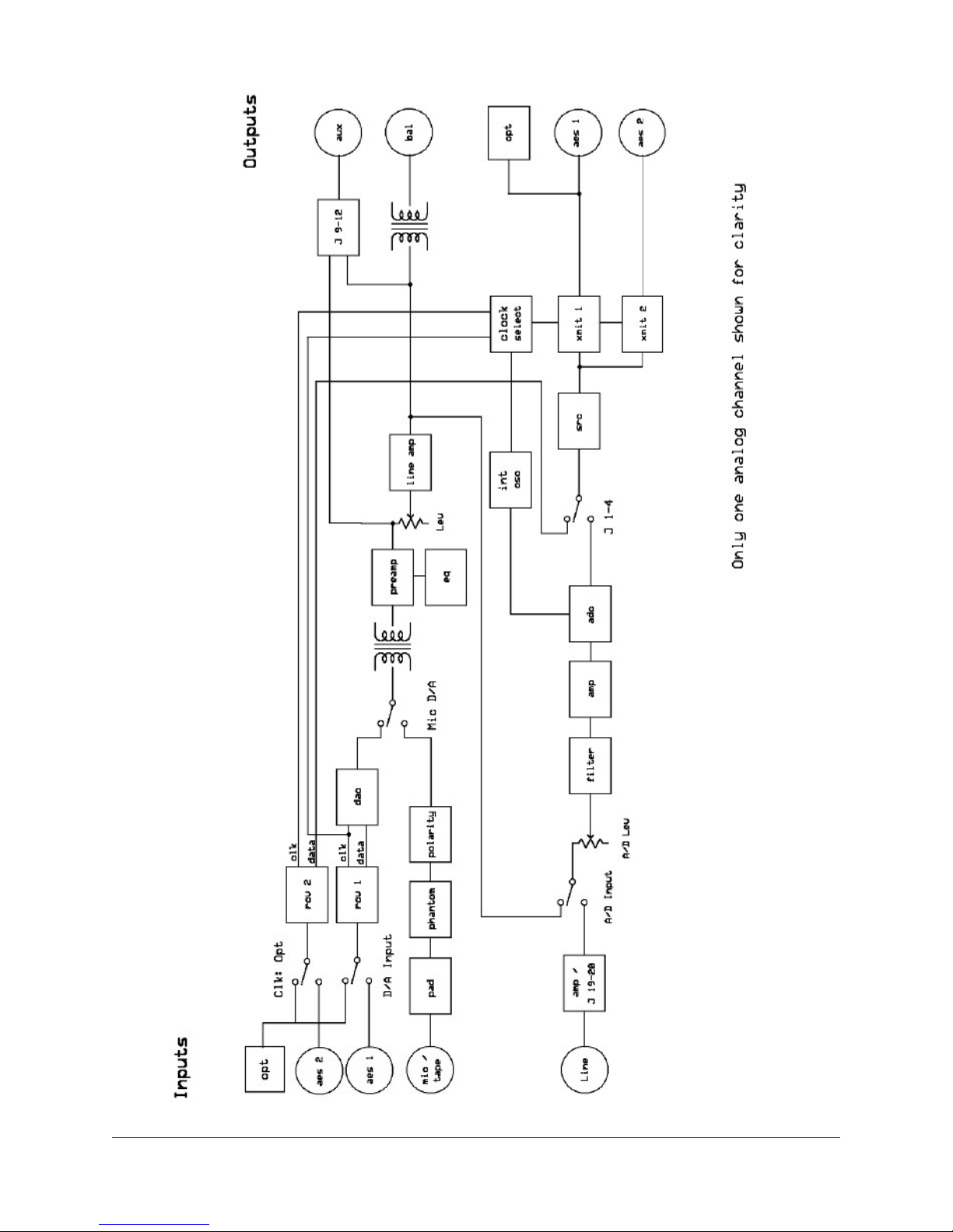
The configuration of the Latte can be tricky. It is designed to be extremely versatile and still do
all of the stated jobs as well as possible. Please learn the block diagram as it will certainly help
you. Flow is mostly from the left to right in the diagram.
Remember, the DMT and A/D sections can work completely independently of one another and
that means completely different speeds and clock sources.
The AES Compatible inputs are self-syncing. This is was designed to provide for simple operation and to meet the desired time-base performance.
A note about bit depth: The D/A will make use of all data presented to it (whether it be 24 or 2
bits) from the AES compatible inputs under all conditions. The AES compatible outputs will
have 24 bits of valid data in the stream under all conditions except internally clocked 192k. This
condition will have 18 bits worth of valid data in the output stream. The lower 6 bits are unmasked will have static junk data in them and can optionally be disregarded. No dither is used
in the Latte anywhere.
J CF Au d io" L att e
16
Page 18

JCF Audio
A fun tip: The Sample Rate Conversion function can be used to make “D to D” copies at the
same sample rate but with asynchronous clock sources. This can sometimes be useful in postproduction environments where CD players (or any digital audio source without the ability to
slave to a reference) can be digitally brought into the fold on-the-fly.
Banter
The Latte is the culmination of all of my work to date with converters, mic pres, transformers,
transistors, and all of the other pieces that go into the unit. After exhaustive listening tests and
prototypes galore over the course of 7 years with such great ears as Doug Sax, Bill Schnee, and
others (who’s names may appear here once I get their permission), I have arrived at this device.
Many of the features of the unit may confuse the average user. Many of the selections of parts
may confuse the tech savvy. Many of the specifications will disappoint those who look to numbers to judge a device's merit. Everything in the Latte is as it is for a reason. Thank you very
much for taking the time to read this manual.
FAQ
1. Q: How come no fancy PLL's
A: Multi-stage PLL's does a wonderful job of attenuating time base problems from the outside world. We at JCF Audio believe that all of the hype surrounding well-designed, more
complex, more expensive multi-stage PLL's is true and they will do exactly what is said and
proved of them time and time again. We at JCF audio also believe that this is not important in
this unit. The simple 1 stage device that is part of the CS8416 AES receiver is absolutely adequate.
2. Q: How come no word clock connections
A: Doing a good job with WC inputs is difficult and for the application just didn't seem useful enough to implement. The addition of WC inputs to the device would also further complicate an already complex, user definable clocking setup. In addition, we hope to avoid it's being
placed in a rack along with some popular clocking products. WC outputs, while much easier to
derive, didn't seem useful either.
If a Latte or Lattes need to be chained such as that they all receive the same AES clock source,
please contact JCF Audio and we will give you some tips as to how one may accomplish that
task.
J CF Au d io" L att e
17
Page 19
JCF Audio
J CF Au d io" L att e
18
Page 20

JCF Audio
3. Q: Why the jumper configurable everything?
A: The jumpers come configured such that most users will not have to adjust them for normal usage. A concerted effort has been made to make certain parameters adjustable to accomodate more complex setups without confusing and cluttering the front or back panels with
controls that most users will not have to address.
4. Q: Why the same electronics block for the D/A as the Mic and Tape circuits.
A: Why not? Every D/A construction (with a few exceptions) will have to utilize an amplifier block (or many) to interface with the outside world. After visiting a great number of combinations of modern opamp configurations, discrete opamps, tubes, etc., the 3 transistor pre / 4
transistor line amp used in the Latte was employed. This combination of amplifier stages (or
very similar ones) were used for years in tape machines and certain microphone preamps and
accomplished the task elegantly and with a small number of components. The DMT sections’
usages as a microphone preamp or tape machine repro were secondary to achieving an elegant,
simple, and time-proven amp section for the D/A function. All of the additional functions of
the Latte presented themselves and were then implemented with great ease and without cramming additional electronics inside the unit.
FCC Compliance:
This device complies with part 15 of the FCC Rules. Operation is subject to the following two
conditions:
(1) This device may not cause harmful interference, and
(2)This device must accept any interference received, including interference that may cause un-
desired operation.
Warranty
JCF Audio 1-Year Limited Warranty
JCF Audio LLC. “JCF Audio” warrants this product to be free of defects in material and assembly for a period of one year for parts and labor from the date of original purchase. This warranty is enforceable only by the original retail purchaser and cannot be transferred or assigned
without express permission of JCF Audio.
During the warranty period JCF Audio shall, at its exclusive option, either repair or replace free
of charge any product that proves to be defective on inspection by JCF Audio or its authorized
service representative. In all cases disputes concerning this warranty shall be resolved as prescribed by law. To obtain warranty service, the purchaser must contact JCF Audio to obtain instructions where to send the unit for service. All authorized returns must be sent to JCF Audio
J CF Au d io" L att e
19
Page 21
JCF Audio
or an authorized JCF Audio repair facility postage prepaid, insured and properly packaged.
This warranty does not cover claims for damage due to abuse, neglect, modification or attempted repair by unauthorized personnel, and is limited to failures arising during normal use
that are due to defects in material or workmanship in the product.
Proof of purchase must be verified in the form of a bill of sale or some other positive proof that
the product is within the warranty period upon JCF Audio’s request.
JCF Audio reserves the right to update any unit returned for repair. JCF Audio reserves the
right to change or improve design of the product at any time without prior notice.
Any implied warranties including implied warranties of merchantability and fitness for a particular purpose are limited in duration to the length of this limited warranty. Some states do not
allow limitations on how long an implied warranty lasts, so the above limitation may not apply
to you.
JCF Audio will not be liable for incidental, consequential, indirect or other damages resulting
from the breach of any express or implied warranty, including damage to property, damage
based on inconvenience, downtime, loss of personal property, and to the extent permitted by
law, damages for personal injury or death.
Some states do allow the exclusion or limitation of incidental or consequential damages, so the
above limitation or exclusion may not apply to you.
This warranty gives you specific legal rights, and you may also have other rights which vary
from state to state.
This warranty only applies to products sold in the United States of America. The terms of this
warranty shall only apply within the country of sale. Without limiting the foregoing, repairs
under this warranty shall be made only by a duly authorized JCF Audio service representative
or by JCF Audio itself. For warranty information in other countries, please refer to the dealer or
distributor.
J CF Au d io" L att e
20
 Loading...