

Page 1
Important warranty information
This product is supported by a 2-year standard warranty. (See website for terms and conditions).
Technical Support: +44(0)1243 838986 Customer Services: +44(0)1243 838999
BS EN ISO9001 - 2015 - Registered Firm Certificate No. GB 1552
Wall mounted PIR
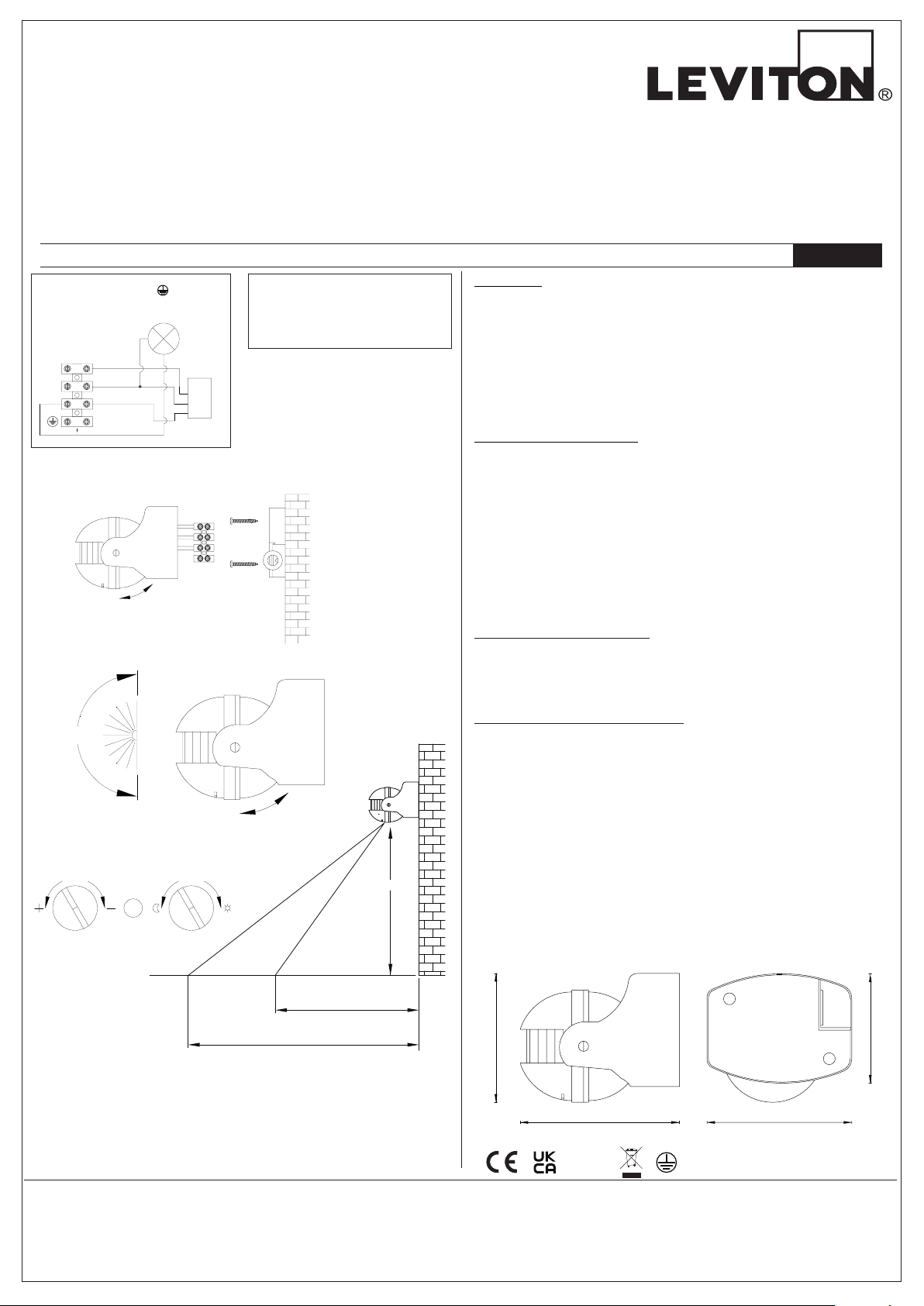
Circuit Diagram
p
TIME
LUX
180°
Angle
of PIR
PIR
m
86mm
95mm
76mm
Installation instructions for LEV68003 stand alone detector
Warnings & Cautions
• To avoid electric shock, serious injury or property damage, isolate power
before installing, removing or servicing the product.
• It is recommended that this product is installed by a qualied electrician
to ensure the installation complies with the local current wiring regulations.
• Any broken or damaged parts should be replaced as soon as possible.
• JCC will not accept responsibility for claims arising from sub-standard
installations; which will void the warranty.
• This product is designed for connection to a 240V~ 50Hz.
INSTALLATION
240V~ 50Hz Class I
Fig. 1
L
N
Brown
Blue
Black
Lam
PIR
PIR Specication
Time Delay:
Detection Distance*:
Detection Range:
Installation Height:
*Detection distance will vary, depending
on installation height
Available nishes: Black & White
Max. 10+5sec. ~4+1min.
Max. 12+2m
180°
2.5m Max.
• It may be necessary to upgrade your MCBs to allow for increased inrush current.
• Do not install in areas that are exposed to continual running water or prone
to ooding.
• Ensure that the mounting surface is both at and stable.
• Never remove the lens cover as this will damage the sensor & render all
warranties invalid.
• Suitable for 1000W halogen only & 300W for LED or CFL only.
ENGLISH
Installation
1. Remove the two screws securing back plate.
2. Use back plate as a template to mark the holes for the xings supplied and
secure to the desired location. See g.2.
3. Feed power supply through the IP rated grommet and terminate wiring as
per Fig.1.
4. Replace main cover and check for operation as shown below.
5. Once powered the PIR will operate; which is indicated by the attached
luminaire ashing three times prior to going in to auto mode.
Positioning The Unit (Fig. 3)
• Read instructions and check that you have all of the tools and accessories
required to complete the installation correctly. Isolate power supply before
starting the installation.
Fig. 2
Fig. 4
Fig. 3
45°
Fig. 5
2.5 Metres
When selecting the mounting position take into account the following points:
1. The sensor is designed for optimum performance when mounted 2.5 meters
above ground level.
2. Avoid positioning close to trees or shrubs; which may cause false triggering
during windy weather.
3. Avoid pointing at or positioning close to heat sources such as u’s of heat
extraction units; which may cause false triggering.
4. Avoid positioning too close to bright lights, the unit will not function when
setting LUX level to dark.
5. The sensor is most sensitive to movement across the detection area as
opposed to directly towards or away from the unit.
The Field of Detection (Fig. 4)
The eld of detection can be adjusted 45° in a vertical direction. By means of
adjustment the permanent 180° eld of detection can be directed to avoid any
false detections from neighbouring grounds or streets.
Operation Mode & Adjusting (Fig. 5)
1. ADJUSTING THE LUX CONTROL LEVEL: The LUX control module has a built in
sensing device (photocell) that detects daylight and darkness by rotating the LUX
knob clockwise or anti clockwise/dark to light, you can set unit to the desired LUX
level. Note: Wait for 5 - 10 seconds for the stability of the photocell (CDS) when
adjusting the LUX level.
2. ADJUSTING THE DURATION TIME: The length of time sensor remains on after
activation can be adjusted from (10±5seconds to 4±1minutes). Rotate the TIME
knob to increase or decrease the duration time. Note: Once the load has been
triggered by the PIR detector any subsequent detection will restart the
time period.
3. The PIR detector will change to MANUAL MODE from AUTO MODE by effective
override switching (ON / OFF mains switch twice within 3 secs).
MANUAL MODE: This will stay in this mode for up to 8 hours. Turn off the override
switch for more than 3 mins to begin new process for MODE CHANGE.
Prole & Dimensions
1 Metre
12 Metres
General Maintenance
JCC recommends that all exterior products, especially those with stainless steel
components are cleaned with warm water and dried with a chamois leather or
absorbent dry cloth. Weathering, environmental pollution and bird droppings
should be cleaned off with a non-abrasive cleaner suitable for the material type.
To preserve the nish of the product, clean every two to three months.
After installation is complete, then bi-annually, grease or lubricate removable
xings, to help ensure maintenance is trouble free.
JCC Lighting Products Ltd. Lux Park, Chichester Business Park, City Fields Way, Tangmere, Chichester, West Sussex, PO20 2FT
RoHS
Compliant
IP44
67m
jcc.co.uk
V5_Sept_2022_RS
 Loading...