

Page 1
Luminaire
Mains Supply
company
a
.
Stage 3
Press springs back and push
luminaire body into aperture.
Connect luminaire to
240V supply cables.
Hybrid7™
JC99701
Downlight
Light source:
Total circuit Wattage:
Lumens:
Efcacy:
Beam angle:
Colour temp:
LED GU10 Module
7.2W
500 Lumens
69 LpcW
38°
4000K
Ra:
80
JC99703
Downlight
Light source:
Total circuit Wattage:
Lumens:
Efcacy:
Beam angle:
Colour temp:
Available nishes: Brushed Nickel, Chrome & White
LED GU10 Module
7.2W
450 Lumens
63 LpcW
38°
3000K
Ra:
80
Installation Sheet
Please read these instructions before installation and retain for future reference
Important Information
It is recommended that luminaires are installed and tted by a qualied electrician ensuring the
installation complies to current IEE wiring regulations and local building control. These products are
designed for connection to a 220-240V~ 50/60Hz Mains supply. This appliance will be considered Class I
with loop-in / loop-out connector. Switch off the mains supply before installation or servicing. This product
is for indoor use only. Ensure area surrounding this luminaire is cleared of any ammable substances. Where
required by building regulations this product may be loosely covered with mineral wool insulation, however
JCC recommends that there be adequate free air ventilation around the luminaire. The light source must
be a minimum distance of 0.3m from a lit object.
Installation
Check you have all the tools and accessories required to complete the installation correctly. Isolate the
power before starting the installation.
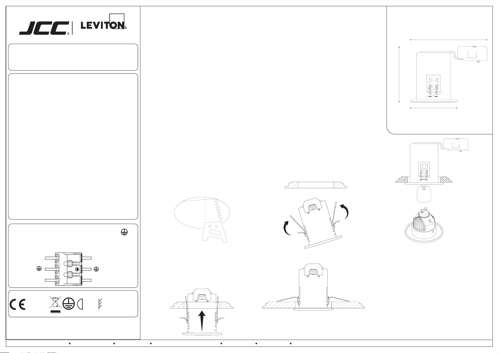
1. Cut the mounting hole in the ceiling, referring to Fig.1 for dimensions. (JCC recommends that a sample
hole is cut in a section of spare material to familiarize yourself with the process).
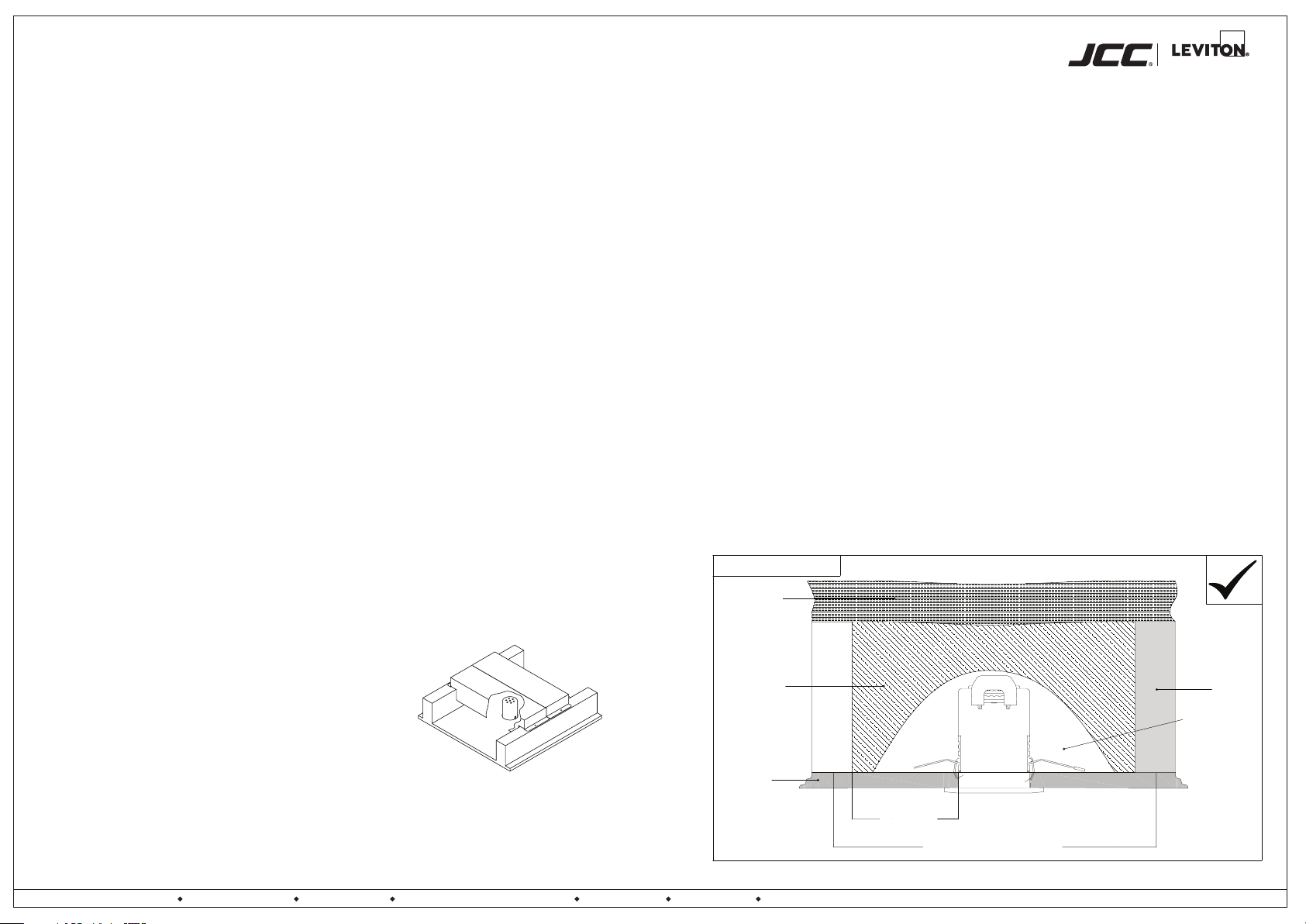
2. The Hybrid7 can be loosley covered with insulation. Ensure there is a minimum of 75mm space around
the tting. Refer to the good practice illustration on page 2 for guidance.
3. Connect the mains supply to the luminaire as per Fig.2.
4. Turn on the power supply to test the tting. Once satised that the luminaire is functioning correctly,
press the spring clips against the side of the luminaire and t into the aperture; as illustrated in Fig.3-5.
Fig.1
Ø72mm
Fig.3
Prole & Dimensions
145mm
104mm
88.6mm
All dimensions in millimetres
GU10
Lampholder Assembly
220-240V~50/60Hz / Class I
Fig.2.
Class I products must always be earthed
(L)
(N)
L
N
Live: Brown
Neutral: Blue
Fig.4
Fig.5
To remove module twist the bezel anti-clockwise and
remove slightly from the can so the lampholder is
visible. Remove the module by twisting anti-clockwise
and pulling the module out of the lampholder.
LED Module
7.2W GU10
For replacement modules please visit:
RoHS
Compliant IP65
BS EN ISO9001 - 2008
Registered Firm Certicate No. GB 1552
Drg No. JC99701-IS Issue: A- 13.01.17 - KB
JCC Lighting Products Ltd. Innovation Centre Beeding Close Southern Cross Trading Estate Bognor Regis West Sussex PO22 9TS Technical Support: 01243 838986 Customer Services: 01243 838999
0.3m
jcc.co.uk
jcc.co.uk/hybrid7
Hybrid7 comes with a 5 year extended warranty
To register please visit: jcc.co.uk/warranty
Prior to registration the installer is asked to provide
the following information directly from the luminaire:
Product code:
Batch number:
Page 2
Installation Recommendations
company
a
Dimming Guidelines
Please use Trailing Edge dimmers only.
Dimmers must not be underloaded or overloaded: underloading may cause the LEDs to ash. If ickering is experienced a different kind of dimmer may be required. Please note: DO NOT perform insulation resistance
tests on a lighting circuit with LED lighting or a dimmer switch connected as this could damage the components in the products beyond repair. A slight buzzing noise may be heard from the dimmer switch while in
operation, however this is perfectly normal. These notes are intended for guidance only. JCC Lighting accepts no responsibility for unsatisfactory installations or consequent loss or damage howsoever caused.
Please Note: These luminaires should not be installed on the same dimming circuit as FGLED 10 or FGLED 6 due to the dimming ratio; which may cause the LEDs to icker. In all cases refer to dimmer switch
manufacturers instructions. For a list of tested/approved dimmers please contact out technical support department or visit our website. Please use Trailing Edge dimmers only.
Part B Fire Safety
The purpose of Part B is to ensure building structures provide adequate protection to personnel to allow the safe evacuation of a building structure/complex. The regulation has been a legal requirement since 1987.
All Hybrid 7 ttings are tested for 30, 60 & 90 minute ceilings (I Joist ceiling construction 30 & 60 minute compliant).
Part C Resistance to Contaminants and Moisture
The amount of moisture that can enter a cold roof void must be controlled; thus anything which punctures the seal between the cold roof area and dwelling area must be considered. Light ttings are a good example
of intrusions into the roof area that can facilitate the passage of moisture. Hybrid 7 downlights have been designed with special seals to inhibit the ow of air & moisture through the tting as required by Part C of the
building regulations.
Part E Resistance to Sound
There is a general increase in the levels of background noise in a domestic environment. The Government has changed to the building regulations to ensure that reasonable noise attenuation can be expected
between partition walls and ceilings not only between separate dwellings but also within individual residential area. The special gaskets incorporated into the Hybrid 7 design ensure that the criteria is met.
Part L Conservation of Fuel and Power
The 2006 revision to Part L has focused lighting installations on energy conservation. There is now a need for 1 in 4 downlights to be energy efcient and have an efciency of >45Lm/w.
Cold Loft Spaces
To prevent accidental damage to the luminaire and to
ensure good air ow around the tting, JCC recommends
the use of a ‘Loft Brace’. This simple solution is designed
to offer mechanical protection over the luminaire allowing
all building and lighting standards to be met. The two
halves of the Loft Brace are slotted together above the
luminaire location as shown and xed to the ceiling joists
using screws (not supplied).
JC94020 Loft Brace for 400mm joist spacing
JC94021 Loft Brace for 600mm joist spacing.
GOOD PRACTICE
Insulation
(150mm thick.)
Insulation
(150mm thick)
Ceiling
75 mm min
400/600mm joist centres
Joist
This area is to
be free from
loose insulation
material
jcc.co.uk Issue: A - 13.01.17 - KB
JCC Lighting Products Ltd. Innovation Centre Beeding Close Southern Cross Trading Estate Bognor Regis West Sussex PO22 9TS Technical Support: 01243 838986 Customer Services: 01243 838999
 Loading...