

Page 1
Copyright © 2004 JCB SERVICE. All rights reserved. No part of this publication may be reproduced, stored in a retrieval system, or transmitted in any form or by any other means,
electronic, mechanical, photocopying or otherwise, without prior permission from JCB SERVICE.
World Class
Customer Support
9803/9360-4
Publication No.
Issued by JCB Technical Publications, JCB Aftermarket Training, Woodseat, Rocester, Staffordshire, ST14 5BW, England. Tel +44 1889 591300 Fax +44 1889 591400
Service Manual
8040ZTS, 8045ZTS, 8050RTS, 8050ZTS
Service Manual - 8040ZTS, 8045ZTS, 8050RTS, 8050ZTS
Section 1
- General Information
Section 2 - Care and Safety
Section 3 - Maintenance
Section A - Attachments
Section B - Body and Framework
Section C - Electrics
Section D - Controls
Section E - Hydraulics
Section F - Gearboxes
Section J - Track and Running Gear
Section K - Engine
4
Page 2

Section 1 - General Information
1-0 1-0
9803/9360-4
Notes:
Page 3

Section 1 - General Information
Contents
1-i 1-i
Page No.Contents
Introduction
About this Manual ............ .......................................................................... 1-1
Machine Model and Serial Number .......................................................1-1
Using the Service Manual .....................................................................1-1
Section Numbering ................................................................................1-1
Left Side, Right Side ..............................................................................1-2
Cross References .................... ... .... ... ... ... .... ..........................................1-2
Identifying Your Machine
Identification Plates ............................................................. ... ................... 1-3
Machine Identification Plate ..................................................................1-3
Typical Vehicle Identification Number (VIN) ..........................................1-3
Typical Product Identification Number (PIN) .........................................1-3
Typical Engine Identification Number ....................................................1-4
ROPS, TOPS and FOGS ......................................................................1-5
Standard Torque Settings
Zinc Plated Fasteners and Dacromet Fasteners ....................................... 1-7
Introduction ................................. ................. ............. ............ ............. ....1-7
Bolts and Screws ............................ ... ... .......................................... ... ....1-7
Hydraulic Connections .................................. .... ... ... ................................. 1-11
'O' Ring Face Seal System ..................................................................1-11
'Torque Stop' Hose System ..... ... .... ... ... ... .... ... ... ... .... ... ... ... ... .... ... ... ... ..1-14
Service Tools
Numerical List .......................................................................................... 1-15
Tool Detail Reference .......... ............................................. ... ... ... .... ... ... ... . 1-18
Section B - Frame and Bodywork ........................................................1-18
Section C - Electrics .......................................................................... ..1-22
Section E - Hydraulics .........................................................................1-23
Section K - Engine ...............................................................................1-28
Service Consumables
Sealing and Retaining Compounds ......................................................... 1-29
Terms and Definitions
Colour Coding .......................................................................................... 1-31
Hydraulic Schematic Colour Codes .......................... ... ... ... ... .... ... ... ... ..1-31
Page 4

Section 1 - General Information
Contents
1-ii 1-ii
Page No.Contents
Page 5

Section 1 - General Information
Introduction
About this Manual
1-1 1-1
9803/9360-4
Introduction
About this Manual
Machine Model and Serial Number
This manual provides information for the following
model(s) in the JCB machine range:
Using the Service Manual
T11-004
This publication is designed for the benefit of JCB
Distributor Service Engineers who are receiving, or have
received, training by JCB Technical Training Department.
These personnel should have a sound knowledge of
workshop practice, safety procedures, and general
techniques associated with the maintenance and repair of
hydraulic earthmoving equipment.
The illustrations in this publication are for guidance only.
Where the machines differ, the text and/or the illustration
will specify.
General warnings in Section 2 are repeated throughout the
manual, as well as specific warnings. Read all safety
statements regularly, so you do not forget them.
Renewal of oil seals, gaskets, etc., and any component
showing obvious signs of wear or damage is expected as
a matter of course. It is expected that components will be
cleaned and lubricated where appropriate, and that any
opened hose or pipe connections will be blanked to
prevent excessive loss of hydraulic fluid and ingress of dirt.
Where a torque setting is given as a sing le figure it may be
varied by plus or minus 3%. Torque figures indicated are
for dry threads, hence for lubricated threads may be
reduced by one third.
The manufacturer's policy is one of continuous
improvement. The right to change the specification of the
machine without notice is reserved. No responsibility will
be accepted for discrepancies which may occur between
specifications of the machine and the descriptions
contained in this publication.
Finally, please remember above all else safety must come
first!
Section Numbering
T11-005
The manual is compiled in sections, the first three are
numbered and contain information as follows:
The remaining sections are alphabetically coded and deal
with Dismantling, Overhaul etc. of specific components, for
example:
Section contents, technical data, circuit descriptions,
operation descriptions etc. are inserted at the beginning of
each alphabetically coded section.
JCB 8040ZTS from serial number 1056000.
JCB 8045ZTS from serial number 1057000.
JCB 8050ZTS from serial number 1741500.
JCB 8050CTS from serial number 1741500.
1 General Information - includes torque settings and
service tools.
2 Care and Safety - includes warnings and cautions
pertinent to aspects of workshop procedures etc.
3 Maintenance - includes service schedules and
recommended lubricants for all the machine.
A Attachments
B Body and Framework, etc.
Page 6
Section 1 - General Information
Introduction
About this Manual
1-2 1-2
9803/9360-4
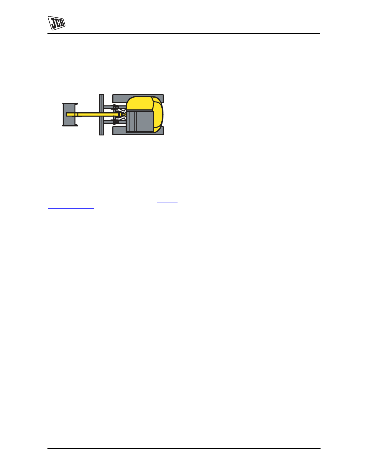
Left Side, Right Side
In this manual, 'left' A and 'right' B mean your left and right
when you are seated correctly in the machine.
Fig 1.
Cross References
T1-004_2
In this publication, page cross references are made by
presenting the subject title printed in bold, italic and
underlined. It is preceeded by the 'go to' symbol. The
number of the page upon which the subject begins, is
indicated within the brackets. For example: K
Cross
References ( T 1-2).
A
B
Page 7
Section 1 - General Information
Identifying Your Machine
Identification Plates
1-3 1-3
9803/9360-4
Identifying Your Machine
Identification Plates
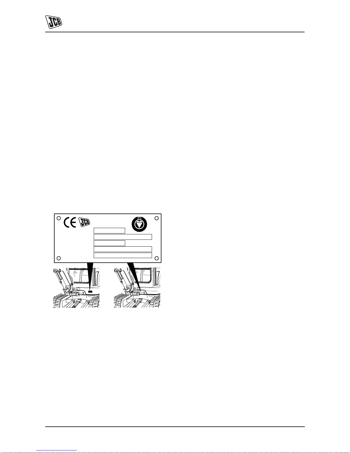
Machine Identification Plate
Your machine has an identification plate mounted as
shown. The Product Identification Number (PIN), weight,
engine power, year of manufacture and serial number of
the machine are shown on the plate.
Note: The machine model and build specification is
indicated by the PIN. Refer to Typical Product
Identification Number (PIN).
If the engine is replaced by a new one, the serial number
on the identification plate will be wrong. Either get a
replacement identification plate from your JCB Dealer or
simply remove the old number. This will prevent the wrong
unit number being quoted when replacement parts are
ordered.
The machine and engine serial numbers can help identify
exactly the type of equipment you have.
Fig 1.
Typical Vehicle Identification Number
(VIN)
1 World Manufacturer Identificati o n (JCB)
2 Machine Type and Model (08045 = 8045)
3 Random Check Letter
4 Year of Manufacture ( 6 = 2006, 7 = 2007, 8 = 2008,
9 = 2009)
5 Product Identification Number (1226501)
Typical Product Identification Number
(PIN)
1 World Manufacturer Identification (3 Digits).
JCB = UK Build.
2 Machine Type and Model (5 Digits).
08040 = 8040.
3 Random Check Letter (1 Digit).
The Check Letter is used to verify the authenticity of
a machine’s PIN.
4 Machine Serial Number (8 Digits).
Each machine has a unique serial number.
S
YEAR OF MANUF.
T
PIN Prod.Ident. No.
ENGINE POWER kW @ RPM
E
I
F
VIN Vehicle Ident. No.
E
R
I
R
M
R
WEIGHT Kg
G
E
D
JCB COMPACT PRODUCTS LIMITED
HAREWOOD ESTATE, LEEK ROAD,
CHEADLE, STOKE ON TRENT,
UNITED KINGDOM, ST10 2JU.
1234 5
JCB 08045 L 7 1226501
123 4
JCB 08040 L 01056000
Page 8
Section 1 - General Information
Identifying Your Machine
Identification Plates
1-4 1-4
9803/9360-4
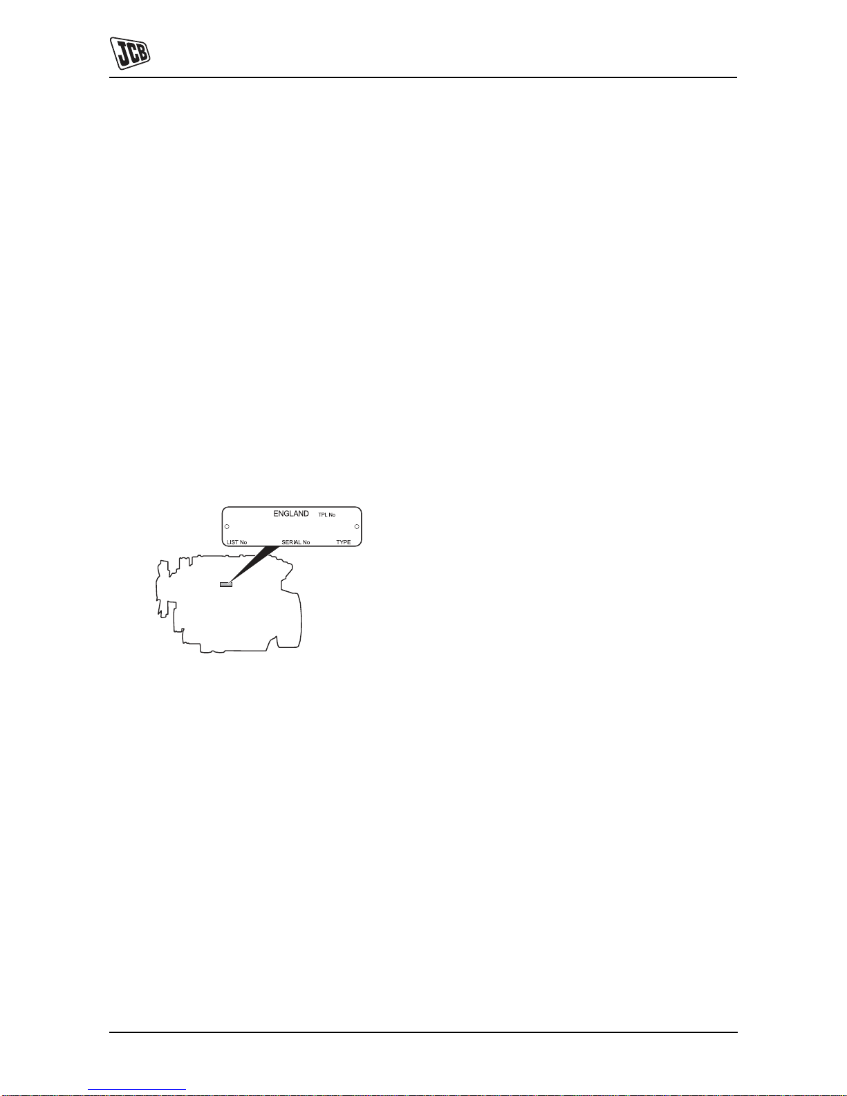
Typical Engine Identification Number
The engine data label is located on the cylinder block as
shown. The data label includes the engine identification
number.
A typical engine identification number is:
1 Engine Type (2 Digits)
2 Country of Manufacture (1 Digit)
U = United Kingdom
3 Build Number (5 Digits)
4 Engine Serial Number (6 Digits)
5 Year of Manufacture (1 Digit)
T017650-2
Fig 2.
GJ U 65692 500405 P
12 3 4 5
GJ = Naturally aspirated, 13.8kW (18.5Hp)
Page 9
Section 1 - General Information
Identifying Your Machine
Identification Plates
1-5 1-5
9803/9360-4
ROPS, TOPS and FOGS
!MWARNING
Modified and wrongly repaired ROPS, TOPS & FOGS
Structures are dangerous. Do not modify the TOPS
Structure. Do not attempt to repair the ROPS, TOPS &
FOGS Structure. If the ROPS, TOPS & FOGS Structure
has been in an accident, do not use the machine until
the structure has been inspected and repaired. This
must be done by a qualified person. For as sistance,
contact your JCB dealer. Failure to take precautions
could result in death or injury to the operator.
5-3-1-7_2
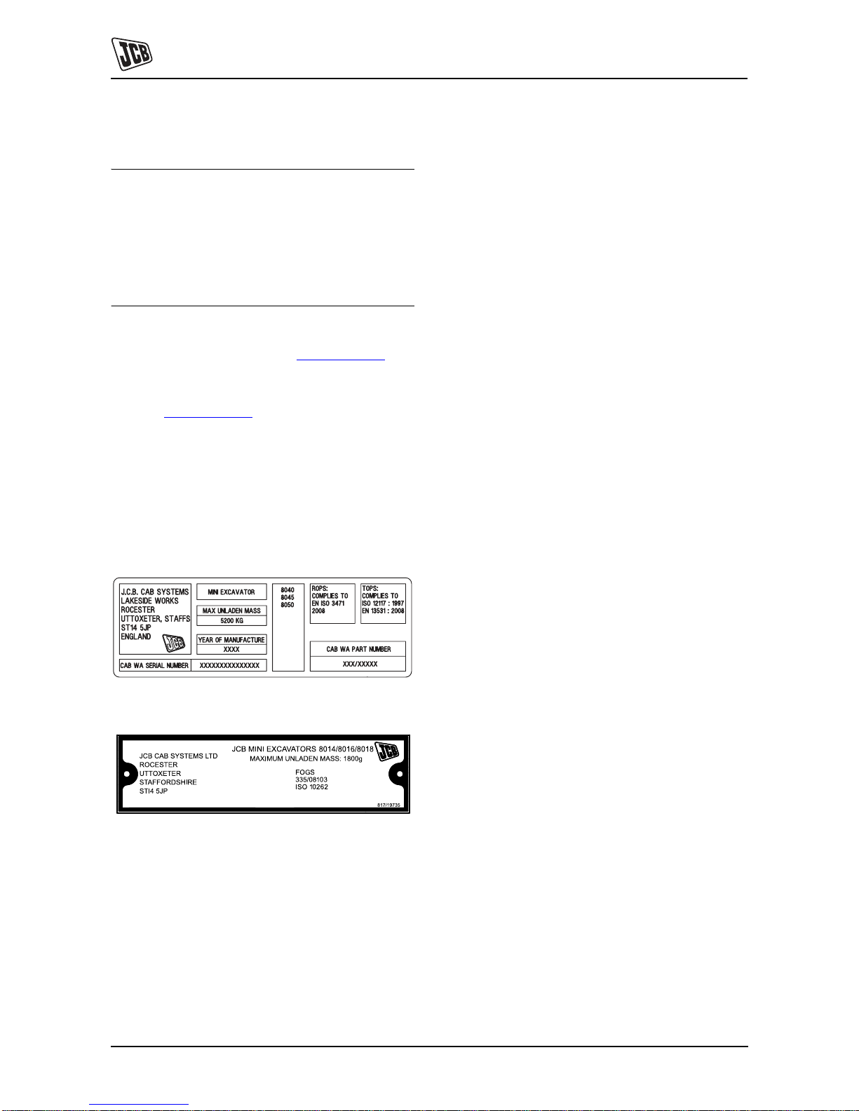
Machines built to ROPS and TOPS standards have an
identification label fitted to the cab. K Fig 3. ( T 1-5).
A bolt on falling object guard is available which also carries
a certified label. This label certifies the cab to FOGS
standard. K
Fig 4. ( T 1-5)
When a machine is used in an application with the risk of
falling objects, the machine must be equipped with the
optional FOGS guard. This guard is compliant to
ISO10262 level 1 and is intended for protection from small
objects, e.g. small rocks, small debris and other small
objects encountered in operations such as highway
maintenance, landscaping and other construction site
services.
332/L7066
Fig 3.
Fig 4.
Page 10

Section 1 - General Information
Identifying Your Machine
Identification Plates
1-6 1-6
9803/9360-4
Page left intentionally blank
Page 11
Section 1 - General Information
Standard Torque Settings
Zinc Plated Fasteners and Dacromet Fasteners
1-7 1-7
9803/9360-3
Standard Torque Settings
Zinc Plated Fasteners and Dacromet Fasteners
T11-002
Introduction
Some external fasteners on JCB machines are
manufactured using an improved type of corrosion
resistant finish. This type of finish is called Dacromet and
replaces the original Zinc and Yellow Plating used on
earlier machines.
The two types of fasteners can be readily identified by
colour and part number suffix. K
Table 1. Fastener Types
( T 1-7).
T ab le1. Fastener Types
Note: As the Dacromet fasteners have a lower torque
setting than the Zinc and Yellow fasteners, the torque
figures used must be relevant to the type of fastener.
Note: A Dacromet bolt should not be used in conjunction
with a Zinc or Yellow plated nut, as this could change the
torque characteristics of the torque setting further. For the
same reason, a Dacromet nut should not be used with a
Zinc or Yellow plated bolt.
Note: All bolts used on JCB machines are high tensile and
must not be replaced by bolts of a lesser tensile
specification.
Note: Dacromet bolts, due to their high corrosion
resistance are used in areas where rust could occur.
Dacromet bolts are only used for external applications.
They are not used in applications such as gearbox or
engine joint seams or internal applications.
Bolts and Screws
Use the following torque setting tables only where no
torque setting is specified in the text.
Note: Dacromet fasteners are lubricated as part of the
plating process, do not lubricate.
Torque settings are given for the following conditions:
Condition 1
– Un-lubricated fasteners
– Zinc fasteners
– Yellow plated fasteners
Condition 2
– Zinc flake (Dacromet) fasteners
– Lubricated zinc and yellow plated fasteners
– Where there is a natural lubrication. For example,
cast iron components
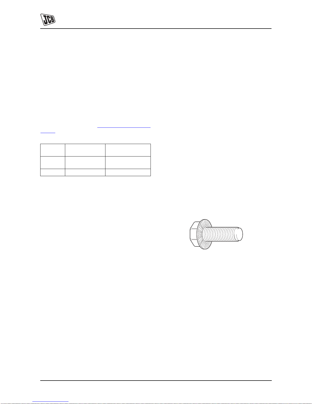
Verbus Ripp Bolts
Fig 1.
Torque settings for these bolts are determined by the
application. Refer to the relevant procedure for the
required settings.
Fastener
Type
Colour Part No. Suffix
Zinc and
Yellow
Golden finish 'Z' (e.g. 1315/3712Z)
Dacromet Mottled silver finish 'D' (e.g. 1315/3712D)
Page 12

Section 1 - General Information
Standard Torque Settings
Zinc Plated Fasteners and Dacromet Fasteners
1-8 1-8
9803/9360-3
Table 2. Torque Settings - UNF Grade 'S' Fasteners
Table 3. Torque Settings - Metric Grade 8.8 Fasteners
Bolt Size Hexagon (A/F) Condition 1 Condition 2
in. mm in. Nm kgf m lbf ft Nm kgf m lbf ft
1/4 6.3 7/16 11.2 1.1 8.3 10.0 1.0 7.4
5/16 7.9 1/2 22.3 2.3 16.4 20.0 2.0 14.7
3/8 9.5 9/16 40.0 4.1 29.5 36.0 3.7 26.5
7/16 11.1 5/8 64.0 6.5 47.2 57.0 5.8 42.0
1/2 12.7 3/4 98.00 10.0 72.3 88.0 9.0 64.9
9/16 14.3 13/16 140.0 14.3 103.2 126.0 12.8 92.9
5/8 15.9 15/16 196.0 20.0 144.6 177.0 18.0 130.5
3/4 19.0 1 1/8 343.0 35.0 253.0 309.0 31.5 227.9
7/8 22.2 1 15/16 547.0 55.8 403.4 492.0 50.2 362.9
1 25.4 1 1/2 814.0 83.0 600.4 732.0 74.6 539.9
1 1/8 31.7 1 7/8 1181.0 120.4 871.1 1063.0 108.4 784.0
1 1/4 38.1 2 1/4 1646.0 167.8 1214.0 1481.0 151.0 1092.3
Bolt Size Hexagon (A/F) Condition 1 Condition 2
ISO Metric
Thread mm mm Nm kgf m lbf ft Nm kgf m lbf ft
M5 5 8 5.8 0.6 4.3 5.2 0.5 3.8
M6 6 10 9.9 1.0 7.3 9.0 0.9 6.6
M8 8 13 24.0 2.4 17.7 22.0 2.2 16.2
M10 10 17 47.0 4.8 34.7 43.0 4.4 31.7
M12 12 19 83.0 8.5 61.2 74.0 7.5 54.6
M16 16 24 205.0 20.9 151.2 184.0 18.8 135.7
M20 20 30 400.0 40.8 295.0 360.0 36.7 265.5
M24 24 36 690.0 70.4 508.9 621.0 63.3 458.0
M30 30 46 1372.0 139.9 1011.9 1235.0 125.9 910.9
M36 36 55 2399.0 244.6 1769.4 2159.0 220.0 1592.4
Page 13

Section 1 - General Information
Standard Torque Settings
Zinc Plated Fasteners and Dacromet Fasteners
1-9 1-9
9803/9360-3
Table 4. Metric Grade 10.9 Fasteners
Table 5. Metric Grade 12.9 Fasteners
Bolt Size Hexagon (A/F) Condition 1 Condition 2
ISO Metric
Thread mm mm Nm kgf m lbf ft Nm kgf m lbf ft
M5 5 8 8.1 0.8 6.0 7.3 0.7 5.4
M6 6 10 13.9 1.4 10.2 12.5 1.3 9.2
M8 8 13 34.0 3.5 25.0 30.0 3.0 22.1
M10 10 17 67.0 6.8 49.4 60.0 6.1 44.2
M12 12 19 116.0 11.8 85.5 104.0 10.6 76.7
M16 16 24 288.0 29.4 212.4 259.0 26.4 191.0
M20 20 30 562.0 57.3 414.5 506.0 51.6 373.2
M24 24 36 971.0 99.0 716.9 874.0 89.1 644.6
M30 30 46 1930.0 196.8 1423.5 1737.0 177.1 1281.1
M36 36 55 3374.0 344.0 2488.5 3036.0 309.6 2239.2
Bolt Size Hexagon (A/F) Condition 1 Condition 2
ISO Metric
Thread mm mm Nm kgf m lbf ft Nm kgf m lbf ft
M5 5 8 9.8 1.0 7.2 8.8 0.9 6.5
M6 6 10 16.6 1.7 12.2 15.0 1.5 11.1
M8 8 13 40.0 4.1 29.5 36.0 3.7 26.5
M10 10 17 80.0 8.1 59.0 72.0 7.3 53.1
M12 12 19 139.0 14.2 102.5 125.0 12.7 92.2
M16 16 24 345.0 35.2 254.4 311.0 31.7 229.4
M20 20 30 674.0 68.7 497.1 607.0 61.9 447.7
M24 24 36 1165.0 118.8 859.2 1048.0 106.9 773.0
M30 30 46 2316.0 236.2 1708.2 2084.0 212.5 1537.1
M36 36 55 4049.0 412.9 2986.4 3644.0 371.6 2687.7
Page 14

Section 1 - General Information
Standard Torque Settings
Zinc Plated Fasteners and Dacromet Fasteners
1-10 1-10
9803/9360-3
Table 6. Torque Settings - Rivet Nut Bolts/Screws
Table 7. Torque Settings - Internal Hexagon Headed Cap Screws (Zinc)
Bolt Size
Nm kgf m lbf ft
ISO Metric
Thread mm
M3 3 1.2 0.1 0.9
M4 4 3.0 0.3 2.0
M5 5 6.0 0.6 4.5
M6 6 10.0 1.0 7.5
M8 8 24.0 2.5 18.0
M10 10 48.0 4.9 35.5
M12 12 82.0 8.4 60.5
Bolt Size
Nm kgf m lbf ft
ISO Metric
Thread
M3 2.0 0.2 1.5
M4 6.0 0.6 4.5
M5 11.0 1.1 8.0
M6 19.0 1.9 14.0
M8 46.0 4.7 34.0
M10 91.0 9.3 67.0
M12 159.0 16.2 117.0
M16 395.0 40.0 292.0
M18 550.0 56.0 406.0
M20 770.0 79.0 568.0
M24 1332.0 136.0 983.0
Page 15

Section 1 - General Information
Standard Torque Settings
Hydraulic Connections
1-11 1-11
9803/9360-3
Hydraulic Connections
T11-003
'O' Ring Face Seal System
Adaptors Screwed into Valve Blocks
Adaptor screwed into valve blocks, seal onto an 'O' ring
which is compressed into a 45° seat machined into the
face of the tapped port.
Table 8. Torque Settings - BSP Adaptors
Table 9. Torque Settings - SAE Connections
BSP Adaptor
Size
Hexagon (A/F)
Nm kgf m lbf ftin. mm
1/4 19.0 18.0 1.8 13.0
3/8 22.0 31.0 3.2 23.0
1/2 27.0 49.0 5.0 36.0
5/8 30.0 60.0 6.1 44.0
3/4 32.0 81.0 8.2 60.0
1 38.0 129.0 13.1 95.0
1 1/4 50.0 206.0 21.0 152.0
SAE Tube
Size
SAE Port
Thread Size
Hexagon (A/F)
Nm kgf m lbf ftmm
4 7/16 - 20 15.9 20.0 - 28.0 2.0 - 2.8 16.5 - 18.5
6 9/16 - 18 19.1 46.0 - 54.0 4.7 - 5.5 34.0 - 40.0
8 3/4 - 16 22.2 95.0 - 105.0 9.7 - 10.7 69.0 - 77.0
10 7/8 - 14 27.0 130.0 - 140.0 13.2 - 14.3 96.0 - 104.0
12 1 1/16 - 12 31.8 190.0 - 210.0 19.4 - 21.4 141.0 - 155.0
16 1 5/16 - 12 38.1 290.0 - 310.0 29.6 - 31.6 216.0 - 230.0
20 1 5/8 47.6 280.0 - 380.0 28.5 - 38.7 210.0 - 280.0
Page 16
Section 1 - General Information
Standard Torque Settings
Hydraulic Connections
1-12 1-12
9803/9360-3
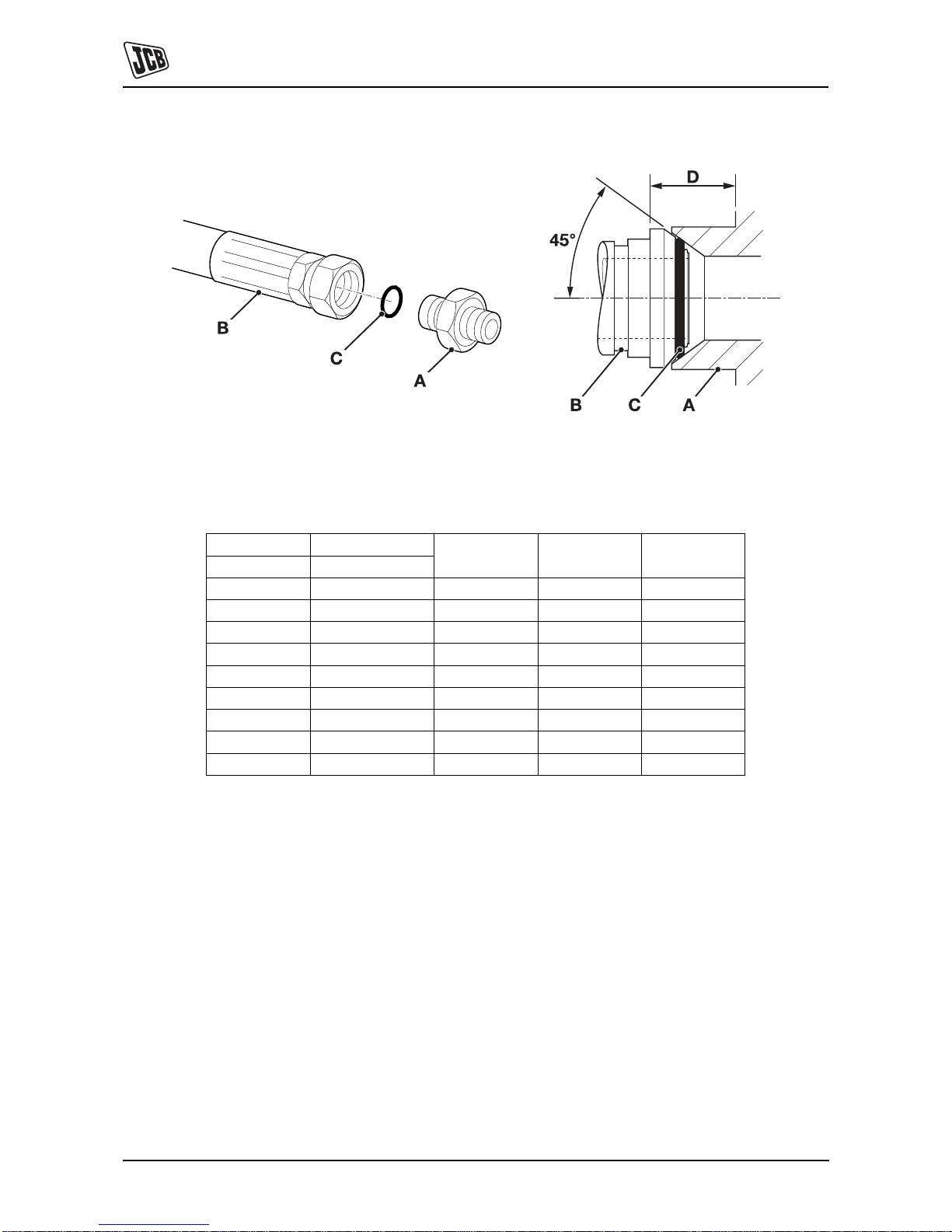
Hoses Screwed into Adaptors
Fig 2.
Hoses 2-B screwed into adaptors 2-A seal onto an `O' ring
2-C which is compressed into a 45° seat machined into the
face of the adaptor port.
Note: Dimension 2-D will vary depending upon the torque
applied.
Table 10. BSP Hose - Torque Settings
BSP Hose Size Hexagon (A/F)
Nm kgf m lbf ftin. mm
1/8 14.0 14.0 - 16.00 1.4 - 1.6 10.3 - 11.8
1/4 19.0 24.0 - 27.0 2.4 - 2.7 17.7 - 19.9
3/8 22.0 33.0 - 40.0 3.4 - 4.1 24.3 - 29.5
1/2 27.0 44.0 - 50.0 4.5 - 5.1 32.4 - 36.9
5/8 30.0 58.0 - 65.0 5.9 - 6.6 42.8 - 47.9
3/4 32.0 84.0 - 92.0 8.6 - 9.4 61.9 - 67.8
1 38.0 115.0 - 126.0 11.7 - 12.8 84.8 - 92.9
1 1/4 50.0 189.0 - 200.0 19.3 - 20.4 139.4 - 147.5
1 1/2 55.0 244.0 - 260.0 24.9 - 26.5 180.0 - 191.8
Page 17

Section 1 - General Information
Standard Torque Settings
Hydraulic Connections
1-13 1-13
9803/9360-3
Adaptors into Component Connections with Bonded W ashers
Table 11. BSP Adaptors with Bonded Washers - Torque Settings
BSP Size
Nm kgf m lbf ftin.
1/8 20.0 2.1 15.0
1/4 34.0 3.4 25.0
3/8 75.0 7.6 55.0
1/2 102.0 10.3 75.0
5/8 122.0 12.4 90.0
3/4 183.0 18.7 135.0
1 203.0 20.7 150.0
1 1/4 305.0 31.0 225.0
1 1/2 305.0 31.0 225.0
Page 18
Section 1 - General Information
Standard Torque Settings
Hydraulic Connections
1-14 1-14
9803/9360-3
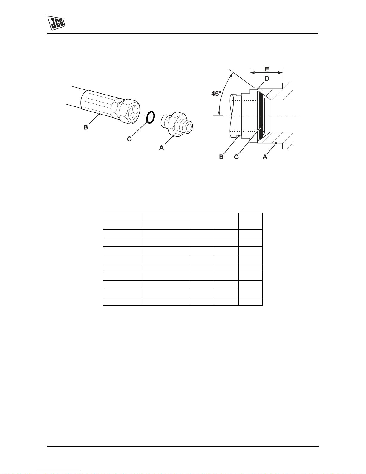
'Torque Stop' Hose System
Fig 3.
`Tor que Stop' Hoses 3-B screwed into adaptors 3-A seal
onto an 'O' ring 3-C which is compressed into a 45° seat
machined in the face of the adaptor port. To prevent the 'O'
ring being damages as a result of over tightening, 'Torque
Stop' Hoses have an additional shoulder 3-D, which acts
as a physical stop.
Note: Mini mum dimension 3-E fixed by shoulder 3-D.
T able 12. BSP `Torque Stop' Hose - Torque Settings
BSP Hose Size Hexagon (A/F)
Nm kgf m lbf ftin. mm
1/8 14.0 14.0 1.4 10.0
1/4 19.0 27.0 2.7 20.0
3/8 22.0 40.0 4.1 30.0
1/2 27.0 55.0 5.6 40.0
5/8 30.0 65.0 6.6 48.0
3/4 32.0 95.0 9.7 70.0
1 38.0 120.0 12.2 89.0
1 1/4 50.0 189.0 19.3 140.0
1 1/2 55.0 244.0 24.9 180.0
Page 19

Section 1 - General Information
Service Tools
Numerical List
1-15 1-15
9803/9360-3
Service Tools
Numerical List
The tools listed in the table are special tools required for
carrying out the procedures described in this manual.
These tools are available from JCB Service.
Some tools are available as kits or sets, the part numbers
for parts within such kits or sets are not listed here. For full
details of all tools, including the content of kits and sets,
refer to Tool Detail Reference, Section 1.
Note: Tools other than those listed will be required. It is
expected that such general tools will be available in any
well equipped workshop or be available locally from any
good tool supplier.
Part
Number
Description See Section
- Bonded Washers - see Tool Detail Reference (Section 1) for content E
- Female Cone Blanking Plugs - see Tool Detail Reference (Section 1) for content E
- Female Connectors - see Tool Detail Reference (Section 1) for content E
- Hydraulic Flow Test Equipment - see Tool Detail Reference (Section 1) for content E
- Hydraulic Hand Pump Equipment - see Tool Detail Reference (Section 1) for content E
- Male Adapters - BSP x BSP - see Tool Detail Reference (Section 1) for content E
- Male Adapters - BSP x NPT (USA only) - see Tool Detail Reference (Section 1) for
content
E
- Male Cone Blanking Caps - see Tool Detail Reference (Section 1) for content E
- Pressure Test Points - Adaptors - see Tool Detail Reference (Section 1) for content E
- Pressure Test Points - 'T' Adaptors - see Tool Detail Reference (Section 1) for content E
- Rivet Nut Tool - see Tool Detail Reference (Section 1) for content B
331/22966 Pump Drive Alignment Tool E
331/31069 T e st Block for A.R.V. E
4104/1310 Hand Cleaner B
892/00039 Spool Clamp E
892/00041 De-glazing Tool K
892/00137 Micro-Bore Hose E
892/00223 Hand Pump E
892/00253 Hydraulic Circuit Pressure Test Kit - see Tool Detail Reference (Section 1) for content E
892/00254 Hose E
892/00271 Adapter E
892/00272 Adapter E
892/00273 Adapter E
892/00274 Adapter E
892/00275 Adapter E
892/00276 Adapter E
Page 20

Section 1 - General Information
Service Tools
Numerical List
1-16 1-16
9803/9360-3
892/00277 Adapter E
892/00279 Gauge E
892/00280 Gauge E
892/00281 AVO Meter C
892/00284 Digital Tachometer C
892/00285 Hyd. Oil Temperature Probe C
892/00298 Fluke Meter C
892/00334 Ram Seal Fitting Tool E
892/00346 Gauge E
892/00347 Connector E
892/00706 T est Probe E
892/00842 Glass Lifter B
892/00843 Folding Stand for Holding Glass B
892/00845 Cartridge Gun B
892/00846 Glass Extractor (Handles) B
892/00847 Nylon Spatula B
892/00848 Wire Starter B
892/00849 Braided Cutting Wire B
892/01016 Ram Protection Sleeve for 25 mm Rod Diameter E
892/01017 Ram Protection Sleeve for 30 mm Rod Diameter E
892/01018 Ram Protection Sleeve for 40 mm Rod Diameter E
892/01019 Ram Protection Sleeve for 50 mm Rod Diameter E
892/01020 Ram Protection Sleeve for 50 mm Rod Diameter (slew ram) E
892/01021 Ram Protection Sleeve for 60 mm Rod Diameter E
892/01022 Ram Protection Sleeve for 60 mm Rod Diameter (slew ram) E
892/01023 Ram Protection Sleeve for 65 mm Rod Diameter E
892/01024 Ram Protection Sleeve for 70 mm Rod Diameter E
892/01025 Ram Protection Sleeve for 75 mm Rod Diameter E
892/01026 Ram Protection Sleeve for 80 mm Rod Diameter E
892/01027 Piston Seal Assembly Tool E
926/15500 Rubber Spacer Blocks B
992/02800 ARV Extractor E
992/04000 Torque Multiplier F
992/09300 Hexagon Spanner 55mm A/F E
992/09400 Hexagon Spanner 65mm A/F E
992/09500 Hexagon Spanner 75mm A/F E
992/09600 Hexagon Spanner 85mm A/F E
Part
Number
Description See Section
Page 21

Section 1 - General Information
Service Tools
Numerical List
1-17 1-17
9803/9360-3
992/09700 Hexagon Spanner 95mm A/F E
992/09900 Hexagon Spanner 115mm A/F E
992/10000 Hexagon Spanner 125mm A/F E
992/10100 Spool Clamp E
992/12300 12V Mobile Oven B
992/12400 24V Static Oven (2 Cartridge) B
992/12800 Cut-Out Knife B
992/12801 'L' Blades B
993/68100 Slide Hammer Kit - see Tool Detail Reference (Section 1) for content B
Part
Number
Description See Section
Page 22

Section 1 - General Information
Service Tools
Tool Detail Reference
1-18 1-18
9803/9360-3
Tool Detail Reference
Section B - Frame and Bodywork
Fig 1. 993/6810 0 Slide Hammer Kit
1 993/68101 Slide Hammer 7 993/68107 Bar - M20 x M20 X 800 mm
2 993/68102 End Stops 8 993/68108 Adaptor - M20 x 7/8" UNF
3 993/68103 Adaptor - M20 x 5/8" UNF 9 993/68109 Adaptor - M20 x M12
4 993/68104 Adaptor - M20 x 1" UNF 10 993/68110 Adaptor - M20 x 5/8" UNF (Shoulder)
5 993/68105 Adaptor - M20 x M20 11 993/68111 Adaptor - M20 x 1/2" UNF
6 993/68106 Adaptor - M20 x M24
Fig 2. Rivet Nut Tool
1 826/01099 M6 x 16 mm Rivet Nut
826/01101 M6 x 19 mm Rivet Nut
826/01102 M8 x 18 mm Rivet Nut
826/01103 M8 x 21 mm Rivet Nut
826/01104 M10 x 23 mm Rivet Nut
826/01105A M 10 x 26 mm Rivet Nut
2 - Installation Tool available from: Bollhoff
Fastenings Ltd (www.bollhof.com)
Page 23

Section 1 - General Information
Service Tools
Tool Detail Reference
1-19 1-19
9803/9360-3
Fig 3. 892/0 0842 Glass Lifter
Minimum 2 off - Essential for glass installation, 2 required
to handle large panes of glass. Ensure suction cups are
protected from damage during storage.
Fig 4. 892/0 0843 Folding Stand
Essential for preparing new glass prior to installation.
Fig 5. 892/00845 Cartridge Gun
Hand operated. Essential for the application of sealants,
polyurethane materials etc.
Fig 6. 892/00846 Glass Extractor (Handles)
Used with braided cutting wire to cut out broken glass.
K
Fig 9. ( T 1-20).
Fig 7. 892/00847 Nylon Spatula
General tool used for smoothing sealants - also used to
re-install glass in rubber glazing because metal tools will
chip the glass edge.
Fig 8. 892/00848 Wire Starter
Used to access braided cutting wire through original
polyurethane seal. K
Fig 9. ( T 1-20).
Page 24

Section 1 - General Information
Service Tools
Tool Detail Reference
1-20 1-20
9803/9360-3
Fig 9. 892/00849 Braided Cutting Wire
Consumable heavy duty cut-out wire used with the glass
extraction tool. K
Fig 6. ( T 1-19). Approx 25 m length.
Fig 10. 926/15500 Rubber Spacer Blocks
Used to provide the correct set clearance between glass
edge and cab frame. Unit quantity = 500 off.
Fig 11. 992/12300 Mobile Oven 12V
1 cartridge capacity. Required to pre-heat adhesive prior
to use. It is fitted with a male plug (703/23201) which fits
into a female socket (715/04300).
Fig 12. 992/12400 Static Oven 240V
Required to pre-heat adhesive prior to use. No plug
supplied.
Note: 110V models available upon request - contact JCB
Technical Service.
Fig 13. 992/12800 Cut-Out Knife
Used to remove broken glass.
Fig 14. 992/12801 'L' Blades
25 mm (1 in.) cut. Replacement blades for cut-out knife.
K
Fig 13. ( T 1-20). Unit quantity = 5 off.
Page 25

Section 1 - General Information
Service Tools
Tool Detail Reference
1-21 1-21
9803/9360-3
Fig 15. 4104/1310 Hand Cleaner
Special blend for the removal of polyurethane adhesives
(454g; 1 lb tub).
Page 26

Section 1 - General Information
Service Tools
Tool Detail Reference
1-22 1-22
9803/9360-3
Section C - Electrics
Fig 16. 892/00298 Fluke Meter
Fig 17. 892/00285 Hydraulic Temperature Probe
Fig 18. 892/00284 Venture Microtach Digita l
Tachometer
Page 27

Section 1 - General Information
Service Tools
Tool Detail Reference
1-23 1-23
9803/9360-3
Section E - Hydraulics
Fig 19. Male Adaptors
Male Adapters - BSP x BSP
1606/2052 3/8 in. x 1/4 in.
1604/0003A 3/8 in. x 3/8 in.
892/00071 3/8 in. x 3/8 in. taper
1606/0004 1/2 in. x 1/4 in.
1606/0007A 1/2 in. x 3/8 in.
1604/0004A 1/2 in. x 1/2 in.
1606/0017 5/8 in. x 1/2 in.
1606/0008 3/4 in. x 3/8 in.
Male Adapters - BSP x NPT (USA only) 1606 /0009 3/4 in. x 1/2 in.
816/00439 3/8 in. x 1/4 in. 1604/2055 3/4 in. x 3/4 in.
816/00440 1/2 in. x 1/4 in. 1606/0012 3/4 in. x 1 in.
816/15007A 3/8 in. x 3/8 in. 1606/0014 3/4 in. x 1.1/4 in.
816/15008 1/2 in. x 3/8 in. 1606/0015 1 in. x 1.1/4 in.
Fig 20. Pressure Test Adapters
892/00255 1/4 in. BSP x Test Point
892/00256 3/8 in. BSP x Test Point
892/00257 1/2 in. BSP x Test Point
892/00258 5/8 in. BSP x Test Point
816/15118 3/4 in. BSP x Test Point
892/00259 1 in BSP x Test Point
892/00260 1.1/4 in. BSP x Test Point
892/00261 5/8 in. UNF x Test Point
Fig 21. Pressure Test 'T' Adapters
816/55045 1/4 in. M BSP x 1/4 in. F BSP x Test Point
816/55038 3/8 in. M BSP x 3/8 in. F BSP x Test Point
816/55040 1/2 in. M BSP x 1/2 in. F BSP x Test Point
892/00263 5/8 in. M BSP x 5/8 in. F BSP x Test Point
892/00264 3/4 in. M BSP x 3/4 in. F BSP x Test Point
892/00265 1 in. M BSP x 1 in. F BSP x Test Point
892/00266 1.1/4 in. M BSP x 1.1/4 in. F BSP x Test Point
892/00267 1.1/4 in. M BSP x 1.1/2 in. F BSP x Test Point
Page 28

Section 1 - General Information
Service Tools
Tool Detail Reference
1-24 1-24
9803/9360-3
Fig 22. 'T' Adapters
892/00047 3/8 in. BSP (A) x 1/4 in. BSP (B)
892/00048 1/2 in. BSP (A) x 1/4 in. BSP (B)
892/00049 5/8 in. BSP (A) x 1/4 in. BSP (B)
816/50043 3/4 in. BSP (A) x 1/4 in. BSP (B)
892/00051 1 in. BSP (A) x 1/4 in. BSP (B)
816/50005 1/2 in. BSP (A) x 1/2 in. BSP (B)
816/60096 3/4 in. BSP (A) x 3/4 in. BSP (B)
816/00017 1 in. BSP (A) x 1 in. BSP (B)
Fig 23. Female Blanking Caps
892/00055A 1/4 in. BSP
892/00056A 3/8 in. BSP
892/00057 1/2 in. BSP
892/00058A 5/8 in. BSP
892/00059A 3/4 in. BSP
892/00060 1 in. BSP
Fig 24. Male Cone Blanking Caps
816/90045 1/4 in. BSP
816/00189A 3/8 in. BSP
816/00190A 1/2 in. BSP
816/90022 5/8 in. BSP
816/90274 3/4 in. BSP
816/90205 1 in. BSP
Fig 25. Female Connecto rs
892/00074 3/8 in. BSP x 3/8 in. BSP
892/00075 1/2 in. BSP x 1/2 in. BSP
892/00076 5/8 in. BSP x 5/8 in. BSP
892/00077 3/4 in. BSP x 3/4 in. BSP
Fig 26. Bonded Washers
1406/0011 1/4 in. BSP
1406/0018 1/2 in. BSP
1406/0014 5/8 in. BSP
1406/0021 3/4 in. BSP
1406/0029 1.1/4 in. BSP
Page 29

Section 1 - General Information
Service Tools
Tool Detail Reference
1-25 1-25
9803/9360-3
Fig 27. Ram Protection Sleeves
892/01016 For 25 mm Rod Diameter
892/01017 For 30 mm Rod Diameter
892/01018 For 40 mm Rod Diameter
892/01019 For 50 mm Rod Diameter
892/01020 For 50 mm Rod Diameter (slew ram)
892/01021 For 60 mm Rod Diameter
892/01022 For 60 mm Rod Diameter (slew ram)
892/01023 For 65 mm Rod Diameter
892/01024 For 70 mm Rod Diameter
892/01025 For 75 mm Rod Diameter
892/01026 For 80 mm Rod Diameter
892/00167 For 90 mm Rod Diameter
Fig 28. 892/00334 Ram Seal Fitting Tool
Fig 29. Hexagon Spanners for Ram Pistons and End
Caps
992/09300 55mm A/F
992/09400 65mm A/F
992/09500 75mm A/F
992/09600 85mm A/F
992/09700 95mm A/F
992/09900 115mm A/F
992/10000 125mm A/F
Fig 30. 892/01027 Piston Seal Assembly Tool
110mm
175mm
R 1.4mm
3
o
R3m
m
7mm
11
o
10mm
2
0mm
5mm
Page 30

Section 1 - General Information
Service Tools
Tool Detail Reference
1-26 1-26
9803/9360-3
Fig 31. Flow Test Equipment
892/00268 Flow Monitoring Unit
892/00269 Sensor Head 0 - 100 l/min (0 - 22 UK gal/min)
892/00273 Sensor Head 0 - 380 l/min (0 - 85.5 UK gal/min)
892/00293 Connector Pipe
892/00270 Load Valve
1406/0021 Bonded Washer
1604/0006A Adapter 3/4 in M x 3/4 in M BSP
1612/2054 Adapter 3/4 in F x 3/4 in M BSP
892/00271 Adapter 3/4 in F x 5/8 in M BSP
892/00272 Adapter 5/8 in F x 3/4 in M BSP
816/20008 Adapter 3/4 in F x 1/2 in M BSP
892/00275 Adapter 1/2 in F x 3/4 in M BSP
892/00276 Adapter 3/4 in F x 3/8 in M BSP
892/00277 Adapter 3/8 in F x 3/4 in M BSP
1606/0015 Adapter 1.1/4 in M BSP x 1 in M BSP
892/00078 Connector 1 in F x 1 in F BSP
1604/0008 Adapter 1 in M x 1 in M BSP
1604/0008 Adapter 1 in M x 3/4 in M BSP
816/20013 Adapter 3/4 in F x 1 in M BSP
Fig 32. 892/ 00253 Hydraulic Circuit Pressure Test Kit
892/00201
Replacement Gauge 0-20 bar (0-300 lbf/in
2
)
892/00202
Replacement Gauge 0-40 bar (0-600 lbf/in2)
892/00203
Replacement Gauge 0-400 bar (0-6000 lbf/in2)
892/00254 Replacement Hose
993/69800 Seal Kit for 892/00254 (can also be used with
probe 892/00706)
892/00706 Test Probe
892/00347 Connector - Hose to gauge
3
2
1
Page 31

Section 1 - General Information
Service Tools
Tool Detail Reference
1-27 1-27
9803/9360-3
Fig 33. Hydraulic Circuit Test Gauges and
Connections
892/00279
Pressure Gauge 0-400 bar (0-6000 lbf/in
2
)
892/00346
Pressure Gauge 0-70 bar (0-1000 lbf/in2)
892/00347 Connector
892/00254 Hose
892/00280
Pressure Gauge 0-600 bar (0-9000 lbf/in
2
)
Fig 34. Hand Pump Equipment
892/00223 Hand Pump
892/00137 Micro-bore Hose 1/4 in BSP x 3 metres
892/00274 Adapter 1/4 in M BSP x 3/8 in M BSP Taper
892/00262 1/4 in M BSP x 1/4 in F BSP x Test Point
892/00706 Test Probe
892/00278
Gauge 0 - 40 bar (0 - 600 lbf/in
2
)
892/00279
Gauge 0 - 400 bar (0 - 6000 lbf/in2)
Fig 35. Spool Clamps
892/00039 Spool Clamp
992/10100 Spool Clamp - Diameter 19mm (3/4 in)
992/02800 ARV Extractor
Fig 36. 331/31069 - Test Block for A.R.V.
Fig 37. 331/22966 Pump Drive Alignment Tool
Page 32

Section 1 - General Information
Service Tools
Tool Detail Reference
1-28 1-28
9803/9360-3
Section K - Engine
For details of other engine service tools refer to:
– Publication No. 9806/2100 English
– Publication No. 9806/2101 French
– Publication No. 9806/2102 German
– Publication No. 9806/2103 Spanish
– Publication No. 9806/2104 Italian
Fig 38. 892/00041 - De-glazing Tool for Cylinder
Bores
To assist bedding -in of new piston ring s.
Page 33

Section 1 - General Information
Service Consumables
Sealing and Retaining Compounds
1-29 1-29
9803/9360-3
Service Consumables
Sealing and Retaining Compounds
T11-001_4
Table 1.
Type Description Part No. Quant ity
JCB Multi-Gasket A medium strength sealant suitable for all sizes of
gasket flanges, and for hydraulic fittings of 25-65 mm
diameter.
4102/1212 50 ml
JCB High Strength Threadlocker A high strength locking fluid for use with threaded
components. Gasketing for all sizes of flange where
the strength of the joint is important.
4102/0551 50 ml
JCB Retainer (High Strength) For all retaining parts which are unlikely to be
dismantled.
4101/0601 10 ml
4101/0651 50 ml
JCB Threadlocker and Sealer A medium strength locking fluid for sealing and
retaining nuts, bolts, and screws up to 50 mm
diameter, and for hydraulic fittings up to 25 mm
diameter.
4101/0250 10 ml
4101/0251 50 ml
JCB Threadlocker and Sealer
(High Strength)
A high strength locking fluid for sealing and retaining
nuts, bolts, and screws up to 50 mm diameter, and
for hydraulic fittings up to 25 mm diameter.
4101/0550 10 ml
4101/0552 200 ml
JCB Threadseal A medium strength thread sealing compound. 4102/1951 50 ml
JCB Activator A cleaning primer which speeds the curing rate of
anaerobic products.
4104/0251 200 ml (Aerosol)
4104/0253 1 ltr (Bottle)
JCB Cleaner/Degreaser For degreasing components prior to use of
anaerobic adhesives and sealants.
4104/1557 400 ml (Aerosol)
Direct Glazing Kit For one pane of glass; comprises of:
– 1 x Ultra Fast Adhesive (310 ml)
– 1 x Active Wipe 205 (30 ml)
– 1 x Black Primer 206J (30 ml)
– plus applicator nozzle etc.
993/55700
Ultra Fast Adhesive For direct glazing. 4103/2109 310 ml
Active Wipe 205 For direct glazing. 4104/1203 250 ml
Black Primer 206J For direct glazing. 4201/4906 30 ml
Clear Silicone Sealant To seal butt jointed glass. 4102/0901
Plastic to Metal Bonder To seal plastic to metal joints. 4103/0956 50 g
Black Polyurethane Sealant To finish exposed edges of laminated glass. 4102/2309 310 ml
Page 34

Section 1 - General Information
Service Consumables
Sealing and Retaining Compounds
1-30 1-30
9803/9360-3
Page left intentionally blank
Page 35

Section 1 - General Information
Terms and Definitions
Colour Coding
1-31 1-31
9803/9360-3
Terms and Definitions
Colour Coding
Hydraulic Schematic Colour Codes
T11-006
The following colour coding, used on illustrations to denote
various conditions of oil pressure and flow, is standardised
throughout JCB Service Publications.
Red
Full Pressure: Pressure generated from operation of a service. Depending on application this
may be anything between neutral circuit pressure and MRV operating pressure.
Pink Pressure: Pressure that is above neutral circuit pressure but lower than that denoted by Red.
Orange Servo: Oil pressure used in controlling a device (servo).
Blue Neural: Neutral circuit pressure.
Green Exhaust
Light Green Cavitation: Oil subjected to a partial vacuum due to a drop in pressure (cavitation).
Yellow Lock Up: Oil trapped within a chamber or line, preventing movement of components (lock up).
Page 36

Section 1 - General Information
Terms and Definitions
Colour Coding
1-32 1-32
9803/9360-3
Page left intentionally blank
Page 37

Section 2 - Care and Safety
2-0 2-0
9803/9360-4
Notes:
Page 38

Page No.Contents
Section 2 - Care and Safety
2-i 2-i
Safety Notices
Important Information ................................................................................ 2-1
The Operator Manual ............................................................................2-1
Safety Warnings ....................................................................................2-1
Safety Check List ....................................................................................... 2-2
Safety - Yours and Others ................................................................. ....2-2
General Safety ......................................................................................2-2
Operating Safety ...................................................................................2-4
Maintenance Safety ...............................................................................2-8
Safety Labels .......... ... ... ... .... ... ... ... ... .... ... ... ... .......................................... . 2-12
Introduction ..................................... ............. ............. ............ ............. ..2-12
Safety Label Identification ...................................................................2-13
Page 39

Page No.Contents
Section 2 - Care and Safety
2-ii 2-ii
Page 40

Section 2 - Care and Safety
2-1 2-1
9803/9360-4
Safety Notices
Important Information
T1-042
The Operator Manual
!MWARNING
You and others can be killed or seriously injured if you
operate or maintain the machine without first studying
the Operator Manual. You must understand and follow
the instructions in the Operator Manual. If you do not
understand anything, ask your employer or JCB
dealer to explain it.
INT-1-4-2
Do not operate the machine without an Operator Manual,
or if there is anything on the machine you do not
understand.
Treat the Operator Manual as part of the machine. Keep it
clean and in good condition. Replace the Operator Manual
immediately if it is lost, damaged or becomes unreadable.
Safety Warnings
In this publication and on the machine, there are safety
notices. Each notice starts with a signal word. The signal
word meanings are given below.
!MDANGER
Denotes an extreme hazard exists. If proper
precautions are not taken, it is highly probable that the
operator (or others) could be killed or seriously
injured.
INT-1-2-1
!MWARNING
Denotes a hazard exists. If proper precautions are not
taken, the operator (or others) could be killed or
seriously injured.
INT-1-2-2
!MCAUTION
Denotes a reminder of safety practices. Failure to
follow these safety practices could result in injury to
the operator (or others) and possible damage to the
machine.
INT-1-2-3
This safety alert system identifies
important safety messages in this
manual. When you see this symbol, be
alert, your safety is involved, carefuly
read the message that follows, and inform
other operators.
Page 41

Section 2 - Care and Safety
Safety Notices
Safety Check List
2-2 2-2
9803/9360-4
Safety Check List
P11-1010_3
Safety - Yours and Others
INT-1-3-1_3
All machinery can be hazardous. When a machine is
correctly operated and properly maintained, it is a safe
machine to work with. But when it is carelessly operated or
poorly maintained it can become a danger to you (the
operator) and others.
In this manual and on the machine you will fin d warning
messages. Read and understand them. They tell you of
potential hazards and how to avoid them. If you do not fully
understand the warning messages, ask your employer or
JCB distributor to explain them.
But safety is not just a matter of responding to the
warnings. All the time you are working on or with the
machine you must be thinking what hazards there might be
and how to avoid them.
Do not work with the machine until you are sure th at you
can control it.
Do not start any job until you are sure that you and those
around you will be safe.
If you are unsure of anything, about the machine or the job,
ask someone who knows. Do not assume anything.
Remember
BE CAREFUL
BE ALERT
BE SAFE
General Safety
T1-043
!MWARNING
To operate the machine safely you must know the
machine and have the skill to use it. You must abide by
all relevant laws, health and safety regulations that
apply to the country you are operating in. The
Operator Manual instructs you on the machine, its
controls and its safe operation; it is not a training
manual. If you are a new operator, get yourself trained
in the skills of using a machine before trying to work
with it. If you don't, you will not do your job well, and
you will be a danger to yourself and others.
INT-1-4-1
!MWARNING
Care and Alertness
All the time you are working with or on the machine,
take care and stay alert. Always be careful. Always be
alert for hazards.
INT-1-3-5
!MWARNING
Clothing
You can be injured if you do not wear the proper
clothing. Loose clothing can get caught in the
machinery. Wear protective clothing to suit the job.
Examples of protective clothing are: a hard hat, safety
shoes, safety glasses, a well fitting overall, earprotectors and industrial gloves. Keep cuffs fastened.
Do not wear a necktie or scarf. Keep long hair
restrained. Remove rings, watches and personal
jewellery.
INT-1-3-6_2
!MWARNING
Alcohol and Drugs
It is extremely dangerous to operate machinery when
under the influence of alcohol or drugs. Do not
consume alcoholic drinks or take drugs before or
while operating the machine or attachments. Be aware
of medicines which can cause drowsiness.
INT-1-3-9_2
Page 42

Section 2 - Care and Safety
Safety Notices
Safety Check List
2-3 2-3
9803/9360-4
!MWARNING
Feeling Unwell
Do not attempt to operate the machine if you are
feeling unwell. By doing so you could be a danger to
yourself and those you work with.
8-1-2-4
!MWARNING
Mobile Phones
Switch off your mobile phone before entering an area
with a potentially explosive atmosphere. Sparks in
such an area could cause an explosion or fire
resulting in death or serious injury.
Switch off and do not use your mobile phone when
refuelling the machine.
INT-3-3-9
!MWARNING
Lifting Equipment
Y ou c a n be inj ure d if y ou us e in c orrec t or fa ulty lifting
equipment. You must identify the weight of the item to
be lifted then choose lifting equipment that is strong
enough and suitable for the job. Make sure that lifting
equipment is in good condition and complies with all
local regulations.
INT-1-3-7_2
!MWARNING
Raised Equipment
Never walk or work under raised equipment unless it
is supported by a mechanical device. Equipment
which is supported only by a hydraulic device can
drop and injure you if the hydraulic system fails or if
the control is operated (even with the engine stopped).
Make sure that no-one goes near the machine while
you install or remove the mechanical device.
13-2-3-7_3
!MWARNING
Raised Machine
NEVER position yourself or any part of your body
under a raised machine which is not properly
supported. If the machine moves unexpectedly you
could become trapped and suffer serious injury or be
killed.
INT-3-3-7_1
!MDANGER
Lightning
Lightning can kill you. Do not use the machine if there
is lightning in your area.
5-1-1-2
!MWARNING
Machine Modifications
This machine is manufactured in compliance with
legislative and other requirements. It should not be
altered in any way which could affect or invalidate any
of these requirements. For advice consult your JCB
Distributor.
INT-1-3-10_2
Page 43

Section 2 - Care and Safety
Safety Notices
Safety Check List
2-4 2-4
9803/9360-4
Operating Safety
!MWARNING
Machine Condition
A defective machine can injure you or others. Do not
operate a machine which is defective or has missing
parts. Make sure the maintenance procedures in this
manual are completed before using the machine.
INT-2-1-2_2
!MWARNING
Machine Limits
Operating the machine beyond its design limits can
damage the machine, it can also be dangerous. Do not
operate the machine outside its limits. Do not try to
upgrade the machine performance with unapproved
modifications.
INT-2-1-4
!MWARNING
Engine/Steering Failure
If the engine or steering fails, stop the machine as
quickly as possible. Do not operate the machine u ntil
the fault has been corrected.
INT-2-1-5
!MWARNING
Exhaust Gases
Breathing the machine exhaust gases can harm and
possibly kill you. Do not operate the machine in closed
spaces without making sure there is good ventilation.
If possible, fit an exhaust extension. If you begin to
feel drowsy, stop the machine at once and get into
fresh air.
INT-2-1-10_2
!MWARNING
Work Sites
Work sites can be hazardous. Inspect the site before
working on it. You could be killed or injured if the
ground gives way under your machine or if piled
material collapses onto it. Check for potholes and
hidden debris, logs, ironwork etc. Any of these could
cause you to lose control of your machine. Check for
utilities such as electric cables (overhead and
underground), gas and water pipes etc. Mark the
positions of the underground cables and pip es. Make
sure that you have enough clearance beneath
overhead cables and structures.
INT-2-2-1_2
!MWARNING
Communications
Bad communications can cause accidents. Keep
people around you informed of what yo u will be doing.
If you will be working with other people, make sure any
hand signals that may be used are understood by
everybody. Work sites can be noisy, do not rely on
spoken commands.
INT-2-2-3
!MWARNING
Parking
An incorrectly parked machine can move without an
operator. Follow the instructions in the Operator
Manual to park the machine correctly.
INT-2-2-4_2
!MWARNING
Banks and Trenches
Banked material and trenches can collapse. Do not
work or drive too close to banks and trenches where
there is danger of collapse.
INT-2-2-5
!MWARNING
Safety Barriers
Unguarded machines in public places can be
dangerous. In public places, or where your visibility is
reduced, place barriers around the work area to keep
people away.
INT-2-2-8
Page 44

Section 2 - Care and Safety
Safety Notices
Safety Check List
2-5 2-5
9803/9360-4
!MDANGER
Sparks
Explosions and fire can be caused by sparks from the
exhaust or the electrical system. Do not use the
machine in closed areas where there is flammable
material, vapour or dust.
INT-2-2-10
!MWARNING
Hazardous Atmospheres
This machine is designed for use in nor mal out door
atmospheric conditions. It should not be used in an
enclosed area without adequate ventilation. Do not
use the machine in a potentially explosive
atmosphere, i.e. combustible vapours, gas or dust,
without first consulting your JCB Distributor.
INT-2-1-14
!MCAUTION
Regulations
Obey all laws, work site and local regulations which
affect you and your machine.
INT-1-3-3
!MWARNING
Practice
You or others can be killed or seriously injured if you
do unfamiliar operations without first practising them.
Practise away from the work site on a clear area. Keep
other people away. Do not perform new operations
until you are sure you can do them safely.
INT-2-1-1
!MWARNING
Airborne particles of light combustible material such
as straw, grass, wood shavings, etc. must not be
allowed to accumulate within the engine compartment
or in the propshaft guards (when fitted). Inspect these
areas frequently and clean at the beginning of each
work shift or more often if required. Before opening
the engine cover, ensure that the top is clear of debris.
5-3-1-12_3
!MWARNING
Keep the machine controls clean and dry. Your hands
and feet could slide off slippery controls. If that
happens you could lose control of the mac hi ne.
2-2-3-6
!MWARNING
Electrical Power Cables
You could be electrocuted or badly burned if you get
the machine or its attachments too close to electrical
power cables.
You are strongly advised to make sure that the safety
arrangements on site comply with the local laws and
regulations concerning work near electric power lines.
Before you start using the machine, check with your
electricity supplier if there are any buried power
cables on the site.
There is a minimum clearance required for working
beneath overhead power cables. You must obtain
details from your local electricity supplier.
2-2-5-4
!MCAUTION
If you have an attachment which is not covered in the
Operator Manual do not install it, use it or remove it
until you have obtained, read and understood the
pertinent information. Install attachments only on the
machines for which they were designed.
5-5-1-1_2
!MWARNING
Use only the JCB approved attachments that are
specified for your machine. Operating with nonspecified attachments can overload the machine,
causing possible damage and machine instability
which could result in injury to yourself or others.
The use of non-approved attachments could invalidate
your warranty.
2-4-5-2_1
Page 45

Section 2 - Care and Safety
Safety Notices
Safety Check List
2-6 2-6
9803/9360-4
!MDANGER
Working Platform
Using the machine as a working platform is
hazardous; you can fall off and be killed or injured.
Never use the machine as a working platform.
5-1-5-9
!MWARNING
Machine Safety
Stop work at once if a fault develops. Abnormal
sounds and smells can be signs of trouble. Ins pect
and repair before resuming work.
8-1-2-3
!MWARNING
Touching hot surfaces can burn skin. The engine and
machine components will be hot after the unit has
been running. Allow the engine and components to
cool before servicing the unit.
10-1-1-40
!MWARNING
Travelling at High Speeds
Travelling at high speeds can cause accidents. Do not
reverse in a high gear with full throttle. Always travel
at a safe speed to suit working conditions.
INT-5-3-3
!MWARNING
The engine has exposed rotating parts. Switch OFF the
engine before working in the engine c ompartment. Do
not use the machine with the engine cover open.
5-2-6-5
!MWARNING
You could be killed or seriously injured if you operate
a machine with a damaged or missing ROPS/FOPS. If
the Roll Over Protection Structure (ROPS)/Falling
Objects Protection Structure (FOPS) has been in an
accident, do not use the machine until th e structure
has been renewed. Modifications and repairs that are
not approved by the manufacturer may be dangero us
and will invalidate the ROPS/FOPS certification.
INT-2-1-9_6
!MWARNING
Machines with a TOPS structure are equipped with a
seat belt. The TOPS structure is designed to give you
protection in an accident. If you do not wear the seat
belt you could be thrown off the machine and crushed.
You must wear a seat belt when using the machine.
Fasten the seat belt before starting the engine.
2-2-1-9
!MWARNING
Hillsides
Operating the machine on hillsides can be dangerous
if proper precautions are not taken. Ground
conditions can be changed by rain, snow, ice etc.
Check the site carefully. When applicable, keep all
attachments low to the ground.
8-1-1-1
!MWARNING
Visibility
Accidents can be caused by working in poor visibility.
Use your lights to improve visibility. Keep the road
lights, windows an d mirrors clean.
Do not operate the machine if you cannot see clearly.
5-1-4-7
!MWARNING
Keep Your Hands and Feet Inside the Vehicle
When using the machine, keep your hands and feet
clear of moving parts. Keep your hands and feet within
the operator compartment while the vehicle is in
motion.
13-1-1-17
!MWARNING
Controls
You or others can be killed or seriously injured if you
operate the control levers from outside the machine.
Operate the control levers only when you are correctly
seated.
0179_2
Page 46

Section 2 - Care and Safety
Safety Notices
Safety Check List
2-7 2-7
9803/9360-4
!MCAUTION
Passengers
Passengers in or on the machine can cause accidents.
Do not carry passengers.
INT-2-2-2_1
!MWARNING
Fires
If your machine is equipped with a fire extinguisher,
make sure it is checked regularly. Keep it in the correct
machine location until you need to use it.
Do not use water to put out a machine fire, you could
spread an oil fire or get a shock from an electrical fire.
Use carbon dioxide, dry chemical or foam
extinguishers. Contact your nearest fire department as
quickly as possible. Firefighters should use selfcontained breathing apparatus.
INT-3-2-7_2
!MWARNING
Should the machine start to roll over, you can be
crushed if you try to leave the cab. If the machine
starts to roll over, do not try and jump from the cab.
Stay in the cab, with your seat belt fastened.
INT-2-1-12
!MWARNING
Seat Belt
Operating the machine without a seat belt can be
dangerous. Before starting the engine, make sure your
seat belt is fastened. Check the tightness and
condition of the seat belt securing bolts regularly (see
maintenance schedules).
INT-2-1-8_1
!MWARNING
Safe Working Loads
Overloading the machine can damage it and make it
unstable. Study the specifications in the Operator
Manual before using the machine.
7-1-1-8_2
!MWARNING
Machine Safety
Stop work at once if a fault develops. Abnormal
sounds and smells can be signs of trouble. Inspect
and repair before resuming work.
8-1-2-3
!MWARNING
Machines with a TOPS structure are equipped with a
seat belt. The TOPS structure is designed to give you
protection in an accident. If you do not wear the seat
belt you could be thrown off the machine and crushed.
You must wear a seat belt when using the machine.
Fasten the seat belt before starting the engine.
2-2-1-9
Page 47

Section 2 - Care and Safety
Safety Notices
Safety Check List
2-8 2-8
9803/9360-4
Maintenance Safety
!MWARNING
Communications
Bad communications can cause accidents. If two or
more people are working on the machine, make sure
each is aware of what the others are doing. Before
starting the engine make sure the others are clear of
the danger areas; examples of danger areas are: the
rotating blades and belt on the engine, the
attachments and linkages, and anywhere beneath or
behind the machine. People can be killed or injured if
these precautions are not taken.
INT-3-1-5
!MWARNING
Repairs
If your machine does not function correctly in any way,
get it repaired straight away. Neglect of necessary
repairs could result in an accident or affect your
health. Do not try to do repairs or any other type of
maintenance work you do not understand. To avoid
injury and/or damage get the work done by a specialist
engineer.
GEN-1-5_2
!MWARNING
Metal Splinters
You can be injured by flying metal splinters when
driving metal pins in or out. Use a soft faced hammer
or copper pin to remove and fit metal pins. Always
wear safety glasses.
INT-3-1-3_2
!MWARNING
Electrical Circuits
Understand the electrical circuit before connecting or
disconnecting an electrical component. A wrong
connection can cause injury and/or damage.
INT-3-1-4
!MWARNING
Fluid Under Pressure
Fine jets of fluid at high pressure can penetrate the
skin. Keep face and hands well clear of fluid under
pressure and wear protective glasses and gloves.
Hold a piece of cardboard close to suspected leaks
and then inspect the cardboard for signs of fluid. If
fluid penetrates your skin, get medical help
immediately.
INT-3-1-10_3
!MWARNING
Hydraulic Pressure
Hydraulic fluid at system pressure can injure you.
Before connecting or removing any hydraulic hose,
residual hydraulic pressure trapped in the service
hose line must be vented. Make sure the hose service
line has been vented before connecting or removing
hoses. Make sure the engine cannot be started while
the hoses are open.
INT-3-1-11_2
!MWARNING
Fuel
Fuel is flammable; keep naked flames away from the
fuel system. Stop the engine immediately if a fuel leak
is suspected. Do not smoke while refuelling or
working on the fuel system. Do not refuel with the
engine running. Completely wipe off any spilt fuel
which could cause a fire. There could be a fire and
injury if you do not follow these precautions.
INT-3-2-2_3
!MWARNING
Oil
Oil is toxic. If you swallow any oil, do not induce
vomiting, seek medical advice. Used engine oil
contains harmful contaminants which can cause skin
cancer. Do not handle used engine oil more than
necessary. Always use barrier cream or wear gloves to
prevent skin contact. Wash skin contaminated with oil
thoroughly in warm soapy water. Do not use petrol,
diesel fuel or paraffin to clean your skin.
INT-3-2-3
Page 48

Section 2 - Care and Safety
Safety Notices
Safety Check List
2-9 2-9
9803/9360-4
!MCAUTION
It is illegal to pollute drains, sewers or the ground.
Clean up all spilt fluids and/or lubricants.
Used fluids and/or lubricants, filters and contaminated
materials must be disposed of in accordance with
local regulations. Use authorised waste disposal sites.
INT-3-2-14
!MWARNING
Soft Ground
A machine can sink into soft ground. Never work
under a machine on soft ground.
INT-3-2-4
!MWARNING
Always wear safety glasses when dismantling
assemblies containing components under pressure
from springs. This will protect against eye injury from
components accidentally flying out.
GEN-6-2
!MCAUTION
Rams
The efficiency of the rams will be affected if they are
not kept free of solidified dirt. Clean dirt from around
the rams regularly. When leaving or parking the
machine, close all rams if possible to reduce the risk
of weather corrosion.
INT-3-2-10
!MCAUTION
Cleaning
Cleaning metal parts with incorrect solvents can cause
corrosion. Use only recommended cleaning agents
and solvents.
INT-3-2-11
!MWARNING
When using cleaning agents, solvents or other
chemicals, you must adhere to the manufacturer's
instructions and safety precautions.
GEN-1-9
!MCAUTION
'O' rings, Seals and Gaskets
Badly fitted, damaged or rotted 'O' rings, seals and
gaskets can cause leakages and possible accidents.
Renew whenever disturbed unless otherwise
instructed. Do not use Triochloroethane or paint
thinners near 'O' rings and seals.
INT-3-2-12
!MWARNING
Hydraulic Hoses
Damaged hoses can cause fatal accidents. Inspect the
hoses regularly. Do not use the machine if a hose or
hose fitting is damaged.
INT-3-3-2_4
!MCAUTION
Waxoyl contains turpentine substitute which is
flammable. Keep flames away when applying Waxoyl.
Waxoyl can take a few weeks to dry completely. Keep
flames away during the drying period.
Do not weld near the affected area during the drying
period. Take the same precautions as for oil to keep
Waxoyl off your skin. Do not breathe the fumes. Apply
in a well-ventilated area.
5-3-1-9
!MWARNING
Working Under the Machine
Make the machine safe before getting beneath it.
Ensure that any fitments on the machine are secure;
engage the park brake, remove the starter key,
disconnect the battery.
INT-3-3-8_2
Page 49

Section 2 - Care and Safety
Safety Notices
Safety Check List
2-10 2-10
9803/9360-4
!MWARNING
Certain seals and gaskets (e.g. crankshaft oil seal) on
JCB machines contain fluoroelastomeric materials
such as Viton®, FluorelTM and Technoflon®.
Fluoroelastomeric materials subjected to high
temperatures can produce highly corrosive
hydrofluoric acid. THIS ACID CAN SEVERELY BURN.
New fluoroelastomeric components at ambient
temperature require no special safety precautions.
Used fluoroelastomeric components whose
temperatures have not exceeded 300°C (572°F) require
no special safety precautions. If evidence of
decomposition (e.g. charring) is found, refer to the
next paragraph for safety instructions DO NOT TOUCH
COMPONENT OR SURROUNDING AREA.
Used fluoroelastomeric components subjected to
temperatures greater than 300°C (572°F) (e.g. engine
fire) must be treated using the following safety
procedure. Make sure that heavy duty gloves and
special safety glasses are worn:
1 Thoroughly wash contaminated area with 10%
calcium hydroxide or other suitable alkali
solution, if necessary use wire wool to remove
burnt remains.
2 Thoroughly wash contaminated area with
detergent and water.
3 Contain all removed material, gloves etc. used in
this operation in sealed plastic bags and dis p os e
of in accordance with Local Authority
Regulations.
DO NOT BURN FLUOROELASTOMERIC MATERIALS.
INT-3-3-5_4
!MWARNING
Protect your eyes when grinding metal. Wear safety
glasses or goggles. Remove or protect any
combustible materials from the area which could be
ignited by sparks.
GEN-1-12
!MWARNING
To avoid burning, wear protective gloves when
handling hot components. To protect your eyes, wear
goggles when using a brush to clean components.
HYD-1-3_2
!MWARNING
Arc Welding
To prevent the possibility of damage to electronic
components, disconnect the battery and the alternator
before arc-welding on the machine or attached
implements.
If the machine is equipped with sensitive electrical
equipment, i.e. amplifier drivers, electronic control
units (E.C.U.s), monitor displays, etc., then disconnect
them before welding. Failure to disconnect the
sensitive electrical equipment could result in
irreparable damage to these components.
Parts of the machine are made from cast iron; welds
on cast iron can weaken the structure and break. Do
not weld cast iron. Do not connect the welder cable or
apply any weld to any part of the engine.
Always connect the welder earth (ground) cable to the
same component that is being welded, i.e. boom or
dipper, to avoid damage to pivot pins, bearings and
bushes. Attach the welder earth (ground) cable no
more than 0.6 metres (2 feet) from the part being
welded.
INT-3-1-15_2
!MWARNING
Counterweights
Your machine may be fitted with counterweights. They
are extremely heavy. Do not attempt to remove them.
INT-3-2-5
!MWARNING
Compressed air is dangerous. Wear suitable eye
protection and gloves. Never point a compressed a ir
jet at yourself or others.
0147_1
Page 50

Section 2 - Care and Safety
Safety Notices
Safety Check List
2-11 2-11
9803/9360-4
!MWARNING
Accumulators
The accumulators contain hydraulic fluid and gas at
high pressure. Prior to any work being carried out on
systems incorporating accumulators, the system
pressure must be exhausted by a JCB distributor, as
the sudden release of the hydraulic fluid or gas may
cause injury.
INT-3-1-17
!MWARNING
Petrol
Do not use petrol in this machine. Do not mix petrol
with the diesel fuel; in storage tanks the petrol will rise
to the top and form flammable vapours.
INT-3-1-6
!MCAUTION
Do not disconnect the battery while the engine is
running, otherwise the electrical circuits may be
damaged.
INT-3-1-14
!MWARNING
If you try to charge a frozen battery, or jump start and
run the engine, the battery could explode. Do not use
a battery if its electrolyte is frozen. To prevent the
battery electrolyte from freezing, keep the battery at
full charge.
0125
!MWARNING
Battery Gases
Batteries give off explosive gases. Keep flames and
sparks away from the battery. Do not smoke close to
the battery. Make sure there is good ventilation in
closed areas where batteries are being used or
charged. Do not check the battery charge by sho rting
the terminals with metal; use an approved battery
tester.
INT-3-1-8_2
!MDANGER
Electrolyte
Battery electrolyte is toxic and corrosive. Do not
breathe the gases given off by the battery. Keep the
electrolyte away from your clothes, skin, mouth and
eyes. Wear safety glasses.
INT-3-2-1_3
!MWARNING
Battery Terminals
The machine is negatively earthed. Always connect
the negative pole of the battery to earth.
When connecting the battery , connect the earth (-) lead
last.
When disconnecting the battery, disconnect the earth
(-) lead first.
INT-3-1-9
!MCAUTION
Never use water or steam to clean inside the cab. The
use of water or steam could damage the on-board
computer and render the machine inoperable. Remove
dirt using a brush or damp cloth.
8-3-4-8
!MWARNING
Asbestos
Asbestos dust can damage your lungs. Some engine
gaskets contain asbestos. Do not dismantle the
engine or exhaust system; get these jobs done by a
qualified person who has a copy of the engine service
manual.
5-1-6-1
!MDANGER
Before removing the boom from the machine, ensure
that the counterweight is adequately supported as in
certain ground conditions the machine could tip
backwards. Never travel or transport the machine with
the boom removed.
BF-6-3
Page 51

Section 2 - Care and Safety
Safety Notices
Safety Labels
2-12 2-12
9803/9360-4
Safety Labels
Introduction
T1-014_2
!MWARNING
Safety Labels
Safety labels on the machine warn you of particular
hazards. You can be injured if you do not obey the
safety instructions shown.
INT-1-3-11
Safety labels are strategically placed around the machine
to remind you of possible hazards.
If you need eye-glasses for reading, make sure you wear
them when reading the safety labels. Do not over-stretch
or place yourself in dangerous positions to read the safety
labels. If you do not understand the hazard shown on the
safety label, then refer to Safety Label Identification.
Note: The illustration(s) show a typical machine model.
Your machine may look different from the model shown.
Keep all safety labels clean and readable. Repl ace lost o r
damaged safety labels. Make sure replacement parts
include safety labels where necessary. Each safety label
has a part number printed on it, use this number to order a
new safety label from your JCB distributor.
Page 52

Section 2 - Care and Safety
Safety Notices
Safety Labels
2-14 2-14
9803/9360-4
ISO-07B
817-70018-2
Part Number: 817/70018
Description: Crush hazard. Do not
operate the controls from outside of
the machine.
ISO-07D
817-70112-2
Part Number: 817/70112
Description: Crush hazard. Keep a
safe distance from the moving parts.
ISO-09A
332-P4581-1
Part Number: 332/P4581
Description: Severing of hands or
fingers. Keep clear of/do not reach
into the moving parts. Stop the engine
and remove the starter key before you
start maintenance work. Refer to
Making the Machine Safe (Routine
Maintenance Section).
ISO-09C
817-70102-3
Part Number: 817/70102
Description: Crushing of fingers or
hands. Remove the starter key and
refer to the Service Manual before you
start maintenance work.
ISO-010A
817-70029-3
Part Number: 817/70029
Description: Crush hazard. Wear the
seatbelt when you operate the
machine.
ISO-12A
817-70106-2
Part Number: 817/70106
Description: Strike to whole body
(machine swing). Keep a safe
distance from the machine.
ISO-11D
817-70100-2
Part Number: 817/70100
Description: Fall. Enter and dismount
safely. Refer to Entering and
Leaving the Cab (Operation
Section).
ISO-11E
817-70006-2
Part Number: 817/70006
Description: Fall. Unexpected
machine movement because of
accidental contact with the machine
controls if the hydraulic functions are
not isolated..
Page 53

Section 2 - Care and Safety
Safety Notices
Safety Labels
2-15 2-15
9803/9360-4
ISO-15E
332-V3761-1
Part Number: 332/V3761
Description: Flying debris warning.
Refer to Optional Attachments.
ISO-09A
332-P4581-1
Part Number: 332/P4581
Description: Severing of hands or
fingers. Keep clear of/do not reach
into the moving parts. Stop the engine
and remove the starter key before you
start maintenance work. Refer to
Making the Machine Safe (Routine
Maintenance Section).
ISO-11A
332-T9356-2
Part Number: 332/T9356
Description: Falling hazard. Lift the
lever lock.
Page 54

Section 2 - Care and Safety
Safety Notices
Safety Labels
2-16 2-16
9803/9360-4
Page left intentionally blank
Page 55

Section 3 - Maintenance
3-0 3-0
9803/9360-4
Notes:
Page 56

Page No.Contents
Section 3 - Maintenance
3-i 3-i
Routine Maintenance
Service Requirements ............................................................................... 3-1
Introduction ................................. ................. ............. ............ ............. ....3-1
Owner/Operator Support .......................................................................3-1
Service/Maintenance Agreements ........................................................3-1
Fit for Purpose Tests for Lifting Equipment ........... .... ... ... ... ... .... .............3-1
Obtaining Replacement Parts ................................................................3-2
Health and Safety ...................................................................................... 3-3
Lubricants ................................................ .............................................. 3-3
Battery ..................................... .............................................................. 3-5
Service Schedules .. ... ... ... .... ... ... .......................................... ... ... .... ... ... ...... 3-7
Introduction ................................. ................. ............. ............ ............. ....3-7
How to Use the Service Schedules .......................................................3-7
Calendar Equivalents ............................................................................3-8
Pre-Start Cold Checks, Service Points and Fluid Levels .......................3-9
Functional Test and Final Inspection ...................................................3-11
Fluids, Lubricants and Capacities ............................................................ 3-12
Coolant Mixtures ........ .... ... ... ... ... .... ... ... ... .......................................... ..3-13
Fuels ..................................... ............. ............. ............. ............. ...........3-14
Tools ........................................................................................................ 3-17
Toolbox (if fitted) ...................................... .... ... ... ... .... ... ... ... ... .... ...........3-17
Carrying Tools onto the Machine .........................................................3-17
Prepare the Machine for Maintenance .................................................... 3-18
Introduction ..................................... ............. ............. ............ ............. ..3-18
How to Make the Machine Safe (Excavator Lowered) ........................3-18
Cleaning the Machine ............. ... ............................................. ... .... ... ... .... 3-19
Introduction ..................................... ............. ............. ............ ............. ..3-19
Preparing the Machine for Cleaning ....................................................3-19
Cleaning the Machine ..........................................................................3-20
Cleaning the Tracks .............................................................................3-20
Checking for Damage ............. ... ... ... .... ... ............................................. ... . 3-22
Check the Machine Body and Structure .............................................. 3-22
Check the Seat and Seat Belt ........................................ ... ... .... ... ... ... ..3-22
Check the Hydraulic Hoses and Fittings .............................................3-22
Check the Electrical Circuits ........... ... .......................................... ... ... ..3-22
Checking the ROPS/FOPS Structure ..................................................3-23
Checking the Ram Piston Rods .............. .... ... ... ... .... ... ... ... ... .... ... ... ... ..3-23
Greasing .................................... ............................................................. . 3-24
Introduction ..................................... ............. ............. ............ ............. ..3-24
Pivot Pins ............................................................................................3-24
Slew Ring Bearings .................................................. ... ... ... ... ...............3-27
Slew Ring Gear Teeth .........................................................................3-27
Access Panels ......................................................................................... 3-29
Introduction ..................................... ............. ............. ............ ............. ..3-29
Engine Cover .......................................................................................3-29
Hydraulic Bay Cover ............................................................................3-30
Electrical System ..................................................................................... 3-31
Battery ..................................... ............................................................ 3-31
Fuses .......................................... ............. ............. ............. ............. .....3-35
Engine ..................................................................................................... 3-37
Oil and Filter ........................................................................................3-37
Cooling System ...................................................................................3-39
Fan Belt ...... ... .... ... ... ... .... ... ... ... ... .......................................... .... ... ... ... ..3-41
Air Filter ...............................................................................................3-42
Page 57

Section 3 - Maintenance
Contents
3-ii 3-ii
Page No.Contents
Fuel System ............................................................................................. 3-43
Introduction ..................................... ............. ............. ............ ............. ..3-43
Water Separator and Engine Fuel Filter .............................................. 3-44
Bleeding the System ............ ... ... .... ... ... ... .... ... ... ... .... ...........................3-47
Hydraulic System .................................... ... ... .... ... .................................... 3-48
Introduction ..................................... ............. ............. ............ ............. ..3-48
Releasing the Hydraulic Pressure .......................................................3-49
Oil and Filter ........................................................................................3-50
Tracks and Running Gear ....................................................................... 3-51
Checking the Track Gearbox Oil Level ................................................3-51
Changing the Track Gearbox Oil .........................................................3-51
Checking the Track Tension ................................................................3-52
Windscreen Washer ...................................................... ... ... ... ... .... ... ... ... . 3-53
Checking the Level ..............................................................................3-53
Fire Extinguisher (if fitted) ........................................................................ 3-54
Checking the Fire Extinguisher ...........................................................3-54
Page 58

Section 3 - Maintenance
3-1 3-1
9803/9360-4
Routine Maintenance
Service Requirements
Introduction
T3-095
Your machine has been designed and built to give
maximum performance, economy and ease of use under a
wide variety of operating conditions. Prior to delivery, your
machine was inspected both at the Factory and by your
Distributor to ensure that it reaches you in optimum
condition. To maintain this condition and ensure trouble
free operation it is important that the routine services, as
specified in this Manual, are carried out by an approved
JCB Distributor at the recommended intervals.
This section of the Manual gives full details of the service
requirements necessary to maintain your JCB machine at
peak efficiency.
A Service Manual for your machine is available from your
JCB Distributor. The Service Manual contains information
on how to repair, dismantle and assemble your machine
correctly.
It can be seen from the Service Schedules on the following
pages that many essential service checks should only be
carried out by a JCB trained specialist. Only JCB
Distributor Service Engineers have been trained by JCB to
carry out such specialist tasks, and only JCB Distributor
Service Engineers are equipped with the necessary
special tools and test equipment to perform such tasks,
thoroughly, safely, accurately and efficiently.
JCB regularly updates its Distributors advising them of any
product developments, changes in specifications and
procedures. Therefore only a JCB Distributor is fully able
to maintain and service your machine.
A Service Record Sheet or Book is provided which will
enable you to plan your service requirements and keep a
service history record. It should be dated, signed and
stamped by your Distributor each time your machine is
serviced.
Remember, if your machine has been correctly
maintained, not only will it give you improved reliability but
its resale value will be greatly enhanced.
Owner/Operator Support
JCB together with your Distributor wants you to be
completely satisfied with your new JCB machine. If you do
encounter a problem however, you should contact your
Distributor's Service Department who are there to help
you!
Y ou will have been given the names of the relevant service
contacts at your Distributor when the machine was
installed.
To ge t the most from your Distributor plea se help them to
satisfy you by:
1 Giving your name, address and telephone number.
2 Quoting your machine model and serial number.
3 Date of purchase and hours of work.
4 Nature of the problem.
Remember, only your JCB Distributor has access to the
vast resources available at JCB to help support you. In
addition, your Distributor is able to offer a variety of
programmes covering Warranty, Fixed Price Servicing,
Safety Inspections, including weight tests, covering both
legal and insurance requirements.
Service/Maintenance Agreements
To help plan and spread the costs of maintaining your
machine, we strongly recommend you take advantage of
the many Service and Maintenance Agreements your
Distributor can offer. These can be tailor made to meet
your operating conditions, work schedule etc.
Please consult your JCB Distributor for details.
Fit for Purpose Tests for Lifting
Equipment
T3-097
All lifting equipment (for example forks, lifting hooks and
shackles) need regular inspection and testing by a
competent person to ensure they are fit for purpose.
Page 59

Thank you very much
for your reading.
Please Click Here
Then Get More
Information.
 Loading...