

Page 1
Quick Start Guide
Compact Excavators
48Z-1/51R-1/55Z-1/57C-1
1
Page 2

Index
Intended Use ......................................................................................................................................3
Dimensions ........................................................................................................................................4
Tie Down Points ................................................................................................................................5
Lifting Points .......................................................................................................................................6
Cab Layout & Controls ................................................................................................................. 7-10
Start Up Sequence ........................................................................................................................... 11
Setting Auxiliary Flows ......................................................................................................................12
Hydraulic Hitch Unlock .....................................................................................................................13
Auxiliary Venting & Shutdown ...........................................................................................................14
Maintenance Position ........................................................................................................................15
Service / Maintenance .......................................................................................................................16
Access Covers .............................................................................................................................17-18
Fluids & Lubricants ............................................................................................................................19
Machine Attachments .......................................................................................................................20
Troubleshooting / FAQs .............................................................................................................. 21-23
This Quick Reference Guide is to provide quick and simple information to the Operator and does not
include any health and safety aspec ts. In addition, because of our continual development of machines,
features described in this Quick Reference Guide may differ from those on your machine. Nor errors and
emissions be entirely ruled out. This Quick Reference Guide DOES NOT replace the Operators Manual.
You MUST read ALL the disclaimers and safety and other instructions in the Operators Manual before
initially operating this product. Accordingly, no legal claims can be entertained on the basis of the data,
illustrations or descriptions in this Quick Reference Guide. This machine should not be operated by any
person who isn’t appropriately qualified or had the appropriate training. Operation of this machine without
periodic maintenance could cause it to malfunction. For more information please contact your JCB Dealer.
2 Please see operator manual for full details.
Page 3

Intended Use
General
> Machine type – Compact Excavator
> Self propelled machine with a tracked undercarriage
> 360° revolving upper structure with boom, dipper, bucket and slew mechanism
Intended Use
> Machine intended to be used in normal conditions as detailed in the operators manual
> With bucket fitted, machine work cycle consists of digging, elevating, slewing and discharging
of materials
> Applications include earthmoving, road construction, building and construction, landscaping etc.
> Can be used for object handling
> Not intended for use in mining and quarrying applications, demolition, forestry, any use
underground and any explosive atmospheres.
> Must not be used for forestry, used with attachments of unknown weight, used on surfaces with
unknown stability – list not exhaustive
>
PPE may be required in certain applications/environments e.g. high silica concentration or asbestos
> The machine should not be operated by any person without appropriate qualifications, training
or experience of using this type pf machine
> Prior to use, the machines suitability should be considered with regards to the intended
applications and any hazards which may be present
48Z-1, 51R-1, 55Z-1, 57C-1 3
Page 4
Dimensions
Fig 1
F
G
H
I
J
L
D
K
E
A
B
C
Machine model 48Z-1 51R-1 55Z-1 57C-1
A Sprocket idler centres mm 198 5
B Track length on ground mm 198 5
C Undercarriage overall length – rubber mm 2490
Undercarriage over all length – steel mm 2490
D Kingpost clearance mm 631
E Tailswing radius mm 975 104 0 1000 130 0
F Overall width of supers tructure mm 1820 1850 1845
G Height over cab mm 25 51 25 61
H Ground clearance mm 300
I Track gauge mm 155 0
J Width over tracks mm 19 50
K Transpor t length with standard dipper mm 5176 5091 5271 5125
L Track height mm 560
M Counterweight clearance mm 618
M
* Standard machine specification, please see data plate for specific machine weight.
4 Please see operator manual for full details.4 Please see operator manual for full details.
Page 5
Dimensions
Fig 2
A Rear track tie- down points
Fig 3
B Front track tie-down points
Note: These measurements are based on a 2500mm wide trailer bed. The correct tie down positions
are identified on the machine by their labels.
Tie Down Posi tion Decal
Fig 4
A Rear track tie-down points
B Front track tie-down points
C Angle = 44.7 ± 5º
D Angle = 43 ± 1.5º
E Length = 2,100 ± 400mm
F Length = 2,200 ± 100mm
48Z-1, 51R-1, 55Z-1, 57C-1 548Z-1, 51R-1, 55Z-1, 57C-1 5
Page 6
Lifting Points
Fig 5
Description 48Z-1 51R-1 55Z-1 57C-1
A Boom Lift Point
B Dozer Lift Point
C 35°
D mm 2400 2480 2320 2220
E mm 4800 4850 4820 4700
F mm 993 1003 993 955
G mm 769 843 875 972
H mm 947 934 961 859
*COG = Centre of Gravity
Fig 6
The correct lifting positions are identified on the machine by their labels: Lifting point
Position label.
6 Please see operator manual for full details.
Page 7
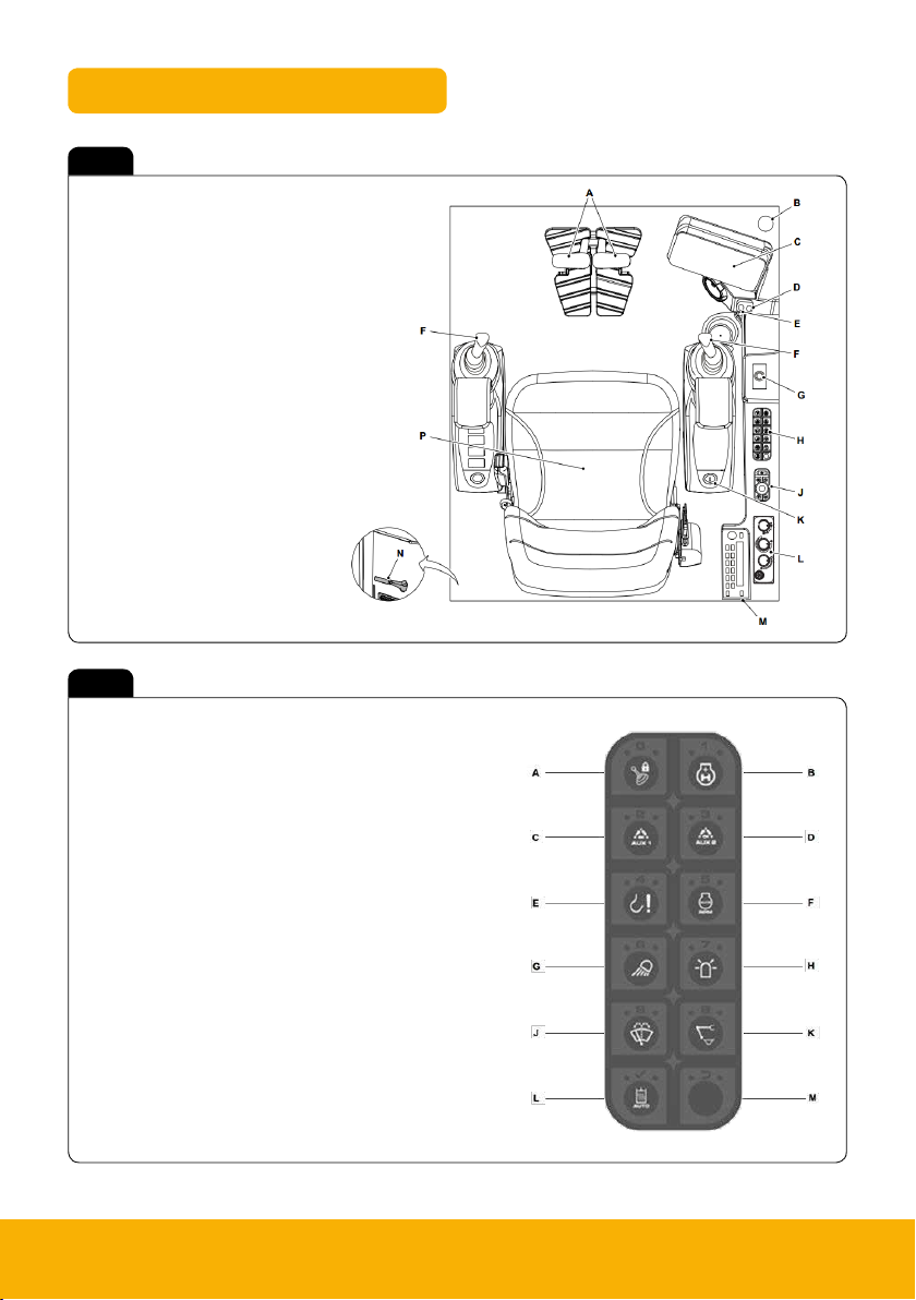
Cab Switch and Panel
Fig 7
A Track controls
B Fire extinguisher
C Instrument panel
D Auxiliary power socket
E USB port
F Excavator controls
G Dozer blade control
H Switch panel
J Rotary switch
K Ignition key switch
L HVAC controls
M Radio
N Glazing breaker
P Operator seat
Fig 8
A 2 Go
B Heavy + mode
C Aux 1 (high flow) selection switch
D Aux 2 (low flow) selec tion switch (opt)
E Lift overload on/off switch (opt)
F Auto idle on/off switch (opt)
G Worklights on/off switch
H Beacon on/off switch (opt)
J Wiper & washer on/off switch (opt)
K Q-hitch sequence switch (opt)
L Auto-hydraulic warming switch
M Blank
Key
(opt) – Option
48Z-1, 51R-1, 55Z-1, 57C-1 7
Page 8
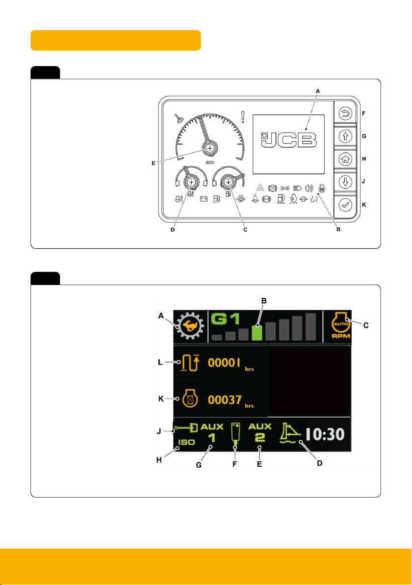
Instrument Panel
Fig 9
A LCD screen
B Warning and indicator lamps
C Fuel level gauge
D Coolant temperature gauge
E Engine speed
F Back button
G Up button
H Home button
J Down button
K Select but ton
Fig 10
A Travel speed status
B Power band status
C Auto idle status
D Dozer float status
E Low flow aux status
F High flow aux mode
G High flow aux status
H ISO/SAE status
J Swing / aux status
K Engine hours status
L Trip hours status
Green – Active / selected
Orange – Status
Grey – Inactive
8 Please see operator manual for full details.
Page 9

Rotary Controller & Work Modes
The rotary controller can be used to both control the machines RPM and to scroll through the menu
system on the machine display (dependant on mode). The rotary can also be used to override the
need to crowd the attachment during the quick hitch sequence (depressing the enter button).
Fig 11 Fig 12
RPM Mode
C
B A
A Toggle power band (rotate)
B One touch idle (press)
C Toggle menu mode but ton
Fig 13 Fig 14
RPM Mode
Rotate dial to cycle through the modes
Low Mode – 1300rpm-1500rpm
Eco Mode – 1600rpm-1800rpm
Heavy (H+) Mode – 1900rpm (2000rpm)
Press to enter H+ Mode
A
E
F
G
A Home button
B Return button
C Toggle through menus (rotate)
D Info screen button
E Toggle menu mode button
F Enter button
G Blank
B
C
D
Info and settings
Lift overload warning
Hydraulic pressure
Auxiliary flow status
Hydraulic oil temperature
Fuel statistics (Kohler only)
48Z-1, 51R-1, 55Z-1, 57C-1 9
Page 10

Joystick & Dozer Lever
Joysticks
Fig 15
Swing Controls
A Swing left
B Swing right
C Swing thumb wheel control
D Swing/Aux change over but ton
Dozer Lever
Fig 17
Fig 16
Auxiliary Controls
A Tilt/grab changeover for tilt-rotator
B Swing/Aux change over button
C Thumb wheel control – Aux 2 (Low flow)
D Continuous flow button – Hammer circuit
E Thumb wheel control – Aux 1 (High flow)
Note: A & D located underside of joystick
G
A Lower the dozer
B Raise the dozer
C Angle the dozer (lef t side in)
D Angle the dozer (right side in)
E Dozer lift/angle changeover
F Dozer float mode on/off
G Travel speed selector
10 Please see operator manual for full details.
Page 11

Start Up Sequence
1
Insert Isolator Key
Insert isolator key (A) and
turn in a clockwise direc tion.
4
Engine Pre Heat
Turn ignition to position 1 (A)
to pre-heat engine before start.
Wait until pre-heat symbol (B)
on instrument panel goes off.
A
B
2
Raise LH Arm Rest
Ensure the hydraulic isolation
lever (left hand arm rest) is in
the raised position.
A Handle
B LH arm rest
5
Disarm Immobiliser
If fitted disarm by entering PIN
code using one of the below
methods.
A B C
3
Engage Seat Belt
Engage seat belt (A) into latch
(B) before starting machine.
6
Start Machine
From ignition position 1 turn
ignition to position 3 (A) to start
the machine.
A
7
Lower LH Arm Rest
Lower the LH arm rest to
activate the hydraulics.
Note: If 2 GO ena bled go to step 8,
if not go to step 9
A Handle
B LH arm rest
8
Press 2 GO Button
If enabled press 2 GO but ton
(A) to activate hydraulics.
Instrument panel will illuminate
(B) when active.
A B
9
Operate Machine
All controls are now active
and the machine is now ready
to use.
48Z-1, 51R-1, 55Z-1, 57C-1 11
Page 12

Setting Auxiliary Flows
1
Enter Menu Mode
Press Menu mode button (A)
on rotary dial to access menus,
icons will illuminate when active.
A
4
Select Aux Mode
Scroll through aux mode
settings using the rotary dial (A)
until on the Aux value you want
to set (B).
B
A B
2
Navigate Menus
Scroll through menus using the
rotary dial (A) until on the aux
setting menu (B).
B
A
5
Set Aux Flow
Press rotar y dial (A) to selec t the
required aux setting then rotate
the dial to adjust setting (B).
A
3
Enter Aux Menu
To enter aux setting menu
press rotary dial (A). Orange
box will appear when menu
active (B).
A
6
Operate Machine
Auxiliary flows are now set to
the desired settings and are
now ready to be used.
B
Aux Activation Aux 1 – High Flow
A
B
Aux 2 – Low Flow
A Aux 1 activation button / mode select
B Aux 2 activation button
12 Please see operator manual for full details.
Single acting hammer – adjustable flow
Aux 1 double acting 1 – rpm set flow
Aux 1 double acting 2 – adjustable flow
Aux 2 double acting – adjustable flow
Page 13

Hydraulic Hitch Unlock Sequence
1
Start Unlock Process
To start quick hitch unlock
process ensure hydraulics are
live then press quick hitch
sequence button (A).
A
4
Remove Attachment
To disengage the pivot pin,
crowd attachment for 3 seconds
then remove attachment.
2
Confirm Process
Instrument panel will indicate
need to confirm process (A).
To confirm process press 2 GO
button (B).
A
5
Change Attachment
Operate the machine to
engage
the jaw (A) with the
attachment
crowd the attachment
to align latch.
(B) and then full
B
3
Boom LED Indicator
When the sequence is
confirmed the LED on the
boom will flash red (A).
A
6
Lock Quick Hitch
To engage the lock on the quick
hitch press one of the following
two but tons and visually check
hitch is locked.
A
B
Specialised Attachments
4a
Crowd Override
For large attachments where
crowding is not possible
press & hold rotary dial (A)
for 5 seconds.
A
4b
Remove Attachment
To disengage the pivot pin
operate use the dozer lift lever
(A) until the hitch unlocks then
remove attachment.
Specialised attachments are any
attachment that when crowded
fully could foul doom/dipper.
When using a specialised
attachment that requires this
process to be followed, replace
No.4 above with No.4 a & b
then continue to follow steps 5
and 6 to finish.
48Z-1, 51R-1, 55Z-1, 57C-1 13
Page 14

Shutdown and Auxiliary Venting
Shutdown Sequence
1
Park Machine Up
Park machine on solid level
ground with the attachment (A)
and dozer (B) on the ground.
2
Leave & Secure
Switch off all switches. Leave
machine using the handrails
and footholds.
Close & lock
all doors and
windows to
secure machine.
Auxiliary Venting (Within 1 Minute of Shutdown)
1
Lower LH Arm Rest
While sitting in the operating
station with engine off lower
LH arm rest.
A Handle
B LH arm rest
2
Turn Ignition On
Turn ignition to position 1 (A) so
that the instrument panel and
switches become active.
A
3
Isolate Machine
Turn isolator key anti-clockwise
and remove key.
A
3
Press 2 GO Button
Press 2 GO but ton (A) to
activate hydraulics. Instrument
panel will illuminate (B)
when active.
A B
4
Activate Aux Venting
Aux 1 but ton on the switch
panel will start to flash, press
(A) to star t auto-venting
sequence.
5
Confirm Venting
Instrument panel will indicate
need to confirm process (A).
To confirm process press 2 GO
button (B).
A
A
14 Please see operator manual for full details.
6
Auxiliary’s Vented
During venting icon on
instrument panel will be green
(A) and buzzer will sound, once
complete the buzzer will stop
B
and the icon will disappear.
A
Page 15

Maintenance Position
1. Park the machine on solid, level ground
I. Release the two track levers
II. Set the hand throttle lever to the idle position
2. Lower the dozer blade (A)
3. Lower the excavator so the attachment is flat on the ground (B)
Fig 18
A
B
A At tachment flat on the ground
B Dozer blade lowered to ground
4. Stop the engine
5. Discharge the hydraulic pressure (see aux venting operation)
6. Isolate the controls and remove ignition key
7. Isolate the battery to prevent accidental operation of the engine
48Z-1, 51R-1, 55Z-1, 57C-1 15
Page 16

Service/Maintenance
Daily Checks (10h) Check
Check condition of at tachments / optional equipment Visual Check
Grease attachments / optional equipment as required Lubricate
Clean bodywork and framework Clean
Check condition of bodywork and framework Visual Check
Check condition of cab/canopy including seat belt Visual Check
Check engine for leaks and oil level Visual Check
Check condition of drive belt Visual Check
Check fuel system for leaks & contamination Visual Check
Drain water from water separator on fuel filter Clean
Check engine coolant for leaks, contamination and level Visual Check
Check condition of cooling pack and system Visual Check
Check hydraulic oil level Visual Check
Check window washer fluid level Visual Check
Check the condition of the fire extinguisher Visual Check
Check operation of all services i.e. excavator, dozer etc. Operate
Check operation of all electrical equipment i.e horn, alarms etc. Operate
Check operation of the hour meter Visual Check
Weekly Checks Check
Grease slew ring bearing Lubricate
Clean cooling pack Clean
Check condition and tension of tracks Visual Check
Check hydraulic hoses / pipework for leaks and damage Visual Check
Check condition of the rams Visual Check
Check the condition of the electrical wiring Visual Check
Clean the battery terminals Clean
Check the operation of the battery isolator Operate
16 Please see operator manual for full details.
Page 17

Access Covers – Kohler Engine
Fig 19
A Air filter
B Radiator
C Hydraulic oil level indicator
D Battery
E Hydraulic oil filler cap
F Fuel filler cap
G Refuelling pump (option)
H Fuel filter
J Battery isolator
Fig 20 Fig 21
K Coolant expansion bottle
L Washer bottle
M Engine fuel filter
N Engine oil dipstick
P Relays / fuses
Fig. 18
P
48Z-1, 51R-1, 55Z-1, 57C-1 17
Page 18

Access Covers – Perkins Engine
Fig 22
A Coolant expansion bottle
B Radiator
C Hydraulic oil level indicator
D Battery
E Hydraulic oil filler cap
F Fuel filler cap
G Refuelling pump (option)
H Fuel filter
J Battery isolator
Fig 23 Fig 24
K Air filter
L Washer bottle
M Engine oil dipstick
18 Please see operator manual for full details.
P Relays / fuses
N
Page 19

Fluids and Lubricants
Item Capacity Fluid/lubricant
Fuel Tank 76L Diesel oil – –
Engine Oil
(Stage 3A Perkins 404D -22)
Engine Oil
(Tier 4 Final Kohler K DI 1903)
Engine Coolant 12L JCB Antifreeze HP / Coolant / Water 4 0 06 /112 0 20L
Track Gearbox (each) 0.8L
Track Idler Wheels 0.8L JCB HD90 Gear Oil 4000/0305 20L
Track Rollers (top) 0.03L JCB HD90 Gear Oil 4000/0305 20L
Track Rollers (bottom) 0.08L JCB HD90 Gear Oil 4000/0305 20L
Hydraulic System 100 L
Hydraulic Tank 55L
Slew Ring Bearing As required JCB HP Grease 40 03/ 2017 0 .4kg
Slew Ring Gear Teeth As required JCB Special Slew Pinion Grease 40 03/1619 0.4kg
All Other Grease As required JCB MPL-EP Grease 4 003/1501 0.4k g
9.1L
9.1L
-30°C (-22°F) to 40°C (104°F):
JCB Ex treme per formance 5W40
-20°C (-4°F ) to 45°C (112.9°F):
JCB Ultra performance 10W30
Below -25°C (-13°F) to 30°C (86°F):
JCB Ultra performance 5W30
Below -25°C (-13°F) to 45°C (113°F):
JCB Ultra performance 5W40
JCB Engine Oil HP SAE 30
(Not Multigrade)
-20°C (-4°F ) to 46°C (114.7°F):
JCB Hydraulic Fluid OP46
-20°C (-4°F ) to 46°C (114.7°F):
JCB Hydraulic Fluid OP46
JCB Par t
Number
40 01/2 70 5 20L
4001/3005 20L
40 01/3105 20L
4001/3405 20L
40 01/0 30 5 20L
4002/2005 20L
4002/2005 20L
Container
Size
JCB par t numbers are liable to change and may also vary by region.
For the latest information, always check with your dealer/distributor.
48Z-1, 51R-1, 55Z-1, 57C-1 19
Page 20

Machine Attachments
Description
Mechanical Quickhitch 29. 3 Quick change of at tachments None
Hydraulic Quickhitch 65 Quick change of at tachments Quickhitch circuit
Bucket GP 250mm 60.2 General excavation / Bulk loading loose material None
Bucket GP 300mm 55.4 General excavation / Bulk loading loose material None
Bucket GP 350 mm 59.4 General excavation / Bulk loading loose material None
Bucket GP 400mm 63.3 General excavation / Bulk loading loose material None
Bucket GP 450 mm 6 7.3 General excavation / Bulk loading loose material None
Bucket GP 600mm 7 9.1 General excavation / Bulk loading loose material None
Bucket GP 750 mm 91.1 General excavation / Bulk loading loose material None
Bucket GP 800mm 95 General excavation / Bulk loading loose material None
Bucket GP 900mm 103 General excavation / Bulk loading loose material None
Grading / Ditching Bucket 1200mm 120 Grading, finishing, landscaping & ditching None
Grading / Ditching Bucket 1500mm 142 Grading, finishing, landscaping & ditching None
Grading / Ditching Bucket 1800mm 164 Grading, finishing, landscaping & ditching None
Earth Drill – 3500 Nm 119 Drilling 160mm – 460mm holes 1 x Hi-Flow aux service
Earth Drill – 6000Nm 122 Drilling 160mm – 460mm holes 1 x Hi-Flow aux service
Breaker – HM026T 260 Breaking up tarmac, concrete, rock
Breaker – HM033T 330 Breaking up tarmac, concrete, rock
Weight
(kg)
Intend ed Use
Hydraulic
Requirements
1 x single ac ting
Hi-Flow aux service
1 x single ac ting
Hi-Flow aux service
20 Please see operator manual for full details.
Page 21

Troubleshooting/FAQs
Issue / FAQ Resolution/Answer
Ensure the start up sequence has been followed (Page 11).
My machine will not start
I can’t activate the Hydraulics
Immobiliser pin from factory is 1945
If machine still will not star t contac t dealer
There are many reasons as to why your 2Go may not work when pressing the
button on the switch panel. Here are some of the possible reasons:
• If the left hand pod is lifted and put back down when machine hydraulics are
“on”, machine hydraulics will disable and not function again until side pod
down and machine in neutral.
• The left hand pod is in the raised position
• There is a fault on the keypad
• Engine isn’t switched on
• If there is an error on the machine and an error code is displayed on the LCD
screen – which would inhibit the hydraulics
• If none of the above, contac t dealer
.
Can I open the Quick Hitch with the
attachment on the ground?
Why is there an audible buzzer in the cab
when I’m lif ting a large load?
Can I disable the lif t overload warning
indicator when not object handling?
The Quick Hitch can be opened with the attachment on the ground. Follow the
instructions previously (Page 13) and at step 4 follow 4a-4b
The lif t overload warning sys tem has detected a load that is near the limits of
the machine, reduce load to prevent machine overturn
To disable lif t overload warning indicator when not object handling press button
no 4 on switch panel
48Z-1, 51R-1, 55Z-1, 57C-1 21
Page 22

Troubleshooting/FAQs
Issue / FAQ Resolution/Answer
500hrs Greasing – Does it mat ter if
greased every day?
No, this only prolongs the life fur ther
500hrs Greasing – Do the bush need to be
replaced at 500hrs?
500hrs Greasing – After the first 500hrs
does the bush then need greasing daily?
500hrs Greasing – Without daily greasing
what cleans all the dir t out of the bush?
Can you dig to dozer?
Why do the tr acks tread look different to
other tracks?
No, just grease and continue work
No, the bush wont need grea sing until the next 50 0hrs
Machine is fitted with a one way seals stopping dirt entering the bush,
but allows old grease out when greasing
Digging to dozer can not be done while machine dig end is central to the dozer.
To dig to dozer slew machine over to the side then use the boom swing to
offset the boom enabling digging up to the dozer
The tread pattern on the tracks is intentional to give the below benefits:
• The Bridgestone tracks will last longer than any other brands
• The reduction in rubber retains life span but reduces waste material
• Reduces lateral slippage, safer operation when traversing slopes
• Allows ef ficient mud release for better grip and less cleaning
• Provides good ride comfor t
22 Please see operator manual for full details.
Page 23

Troubleshooting/FAQs
Issue / FAQ Resolution/Answer
Are the old 8040 -8065 at tachments
compatible?
The pick up geometry has changed to enable compatibilit y with competitor
attachments. To enable pick up of old attachments the specific hydraulic quick
hitch is required. Cont act dealer for more details if required
How is the “ follow me home” lights
system activated?
How to I activate continuous auxiliary flow?
What are the max flow of the
Auxiliary circuits?
What are the auxiliary flow settings when
in Aux 1 double acting mode 1?
If LED lights are fitted the machine is capable of the follow me home func tion.
To activate when shutting machine down the work light button on the switch
panel will flash, press to activate for 3 minutes of light
Continuous flow but ton is located on the underside of the right hand joystick
This button has t wo functions, the ac tive func tion is set in the setup menu:
1) Latched auxiliary flow
2) Press & hold auxiliary flow
The maximum flow for the hydraulic circuits are as follows:
• High flow – 90l/min
• Low flow – 40l/min
Engine Power Band % Max Aux Flow Aux Flow L /min
L1 30% 27
L2 40% 36
L3 50% 45
G1 60% 54
G2 70% 63
G3 80% 72
H 90% 81
H+ 100% 90
48Z-1, 51R-1, 55Z-1, 57C-1 23
Page 24

JCB Sales Limited, Rocester, Staffordshire, United Kingdom ST14 5JP
Tel: +44 1889 590312 Email: salesinfo@jcb.com
Download the very latest information on this product range at: w ww.jcb.com
The JCB lo go is a registered t rademark of J C Ba mford Excavator s Ltd. ©2009 JCB Sale s. All rights res erved. No par t of this publica tion may be reprodu ced, stored in a ret rieval system,
or transm itted in any form or by any other means, electronic, m echanical, photo copying or other wise, without p rior permissi on from JCB Sales . All references in this publicati on to
operati ng weights, sizes, c apacities and o ther perform ance measuremen ts are provided fo r guidance only an d may vary depen dant upon the exa ct specificat ion of the machine. They should
not theref ore be relied upon i n relation to suit ability for a pa rticular app lication. Guid ance and advice sh ould always be sou ght from your JCB De aler’. JCB reserve s the right to change
specific ations withou t notice. Illust rations and spe cifications sh own may include opt ional equipmen t and accessories .
9818/3 050
 Loading...