

Page 1
Quick Start Guide
Compact Wheeled Loader
406, 407 & 409
1
Page 2

Disclaimer Index
Intended Use ......................................................................................................................................4
>
This Quick Reference Guide is to provide quick and simple information to the Operator
and does not include any health and safety aspects. In addition, because of our continual
development of machines, features described in this Quick Reference Guide may differ
from those on your machine. No errors and emissions be entirely ruled out.
Dimensions ....................................................................................................................................5-7
Tie Down/ Lifting Points .....................................................................................................................8
Lifting Points ................................................................................................................................. 9 -10
>
This Quick Reference Guide DOES NOT replace the Operators Manual. You MUST
read ALL the disclaimers and safety and other instructions in the Operators Manual
before initially operating this product. Accordingly, no legal claims can be entertained on
the basis of the data, illustrations or descriptions in this Quick Reference Guide.
>
This machine should not be operated by any person who isn’t appropriately qualified or
had the appropriate training.
>
Operation of this machine without periodic maintenance could cause it to malfunction.
For more information please contact your JCB Dealer.
Cab Layout & Controls ................................................................................................................11-19
Start Up Sequence ...........................................................................................................................20
Shutdown Sequence .........................................................................................................................21
Maintenance Position ........................................................................................................................22
Service/ Maintenance ..................................................................................................................23-25
Fluids & Lubricants ............................................................................................................................26
Attachments .....................................................................................................................................27
Troubleshooting/ FAQs .....................................................................................................................28
Your Notes .................................................................................................................................29-31
23Please see operator manual for full details.
406, 407 & 409
Page 3
Intended Use Dimensions
General
> Machine Type – Compact Wheeled Loader
> 406,407 &409 front end ar ticulated Loader
Intended Use
> Machine intended to be used in normal conditions
> With bucket fitted, machine work cycle consists of digging and discharging of materials
> Applications include earthmoving, road construction, building and construction, landscaping etc.
> Can be used for object handling
> Not intended for use in mining and quarrying applications, demolition, forestry and any
explosive atmospheres
> Must not be used with attachments of unknown weight, used on surfaces with unknown stability
– list not exhaustive
> PPE may be required in certain applications/environments e.g. high silica concentration or asbestos
> The machine should not be operated by any person who isn’t appropriately qualified or had the
correct training
> Prior to use, the machines suitability should be considered with regards to the intended applications
and any hazards which may be present
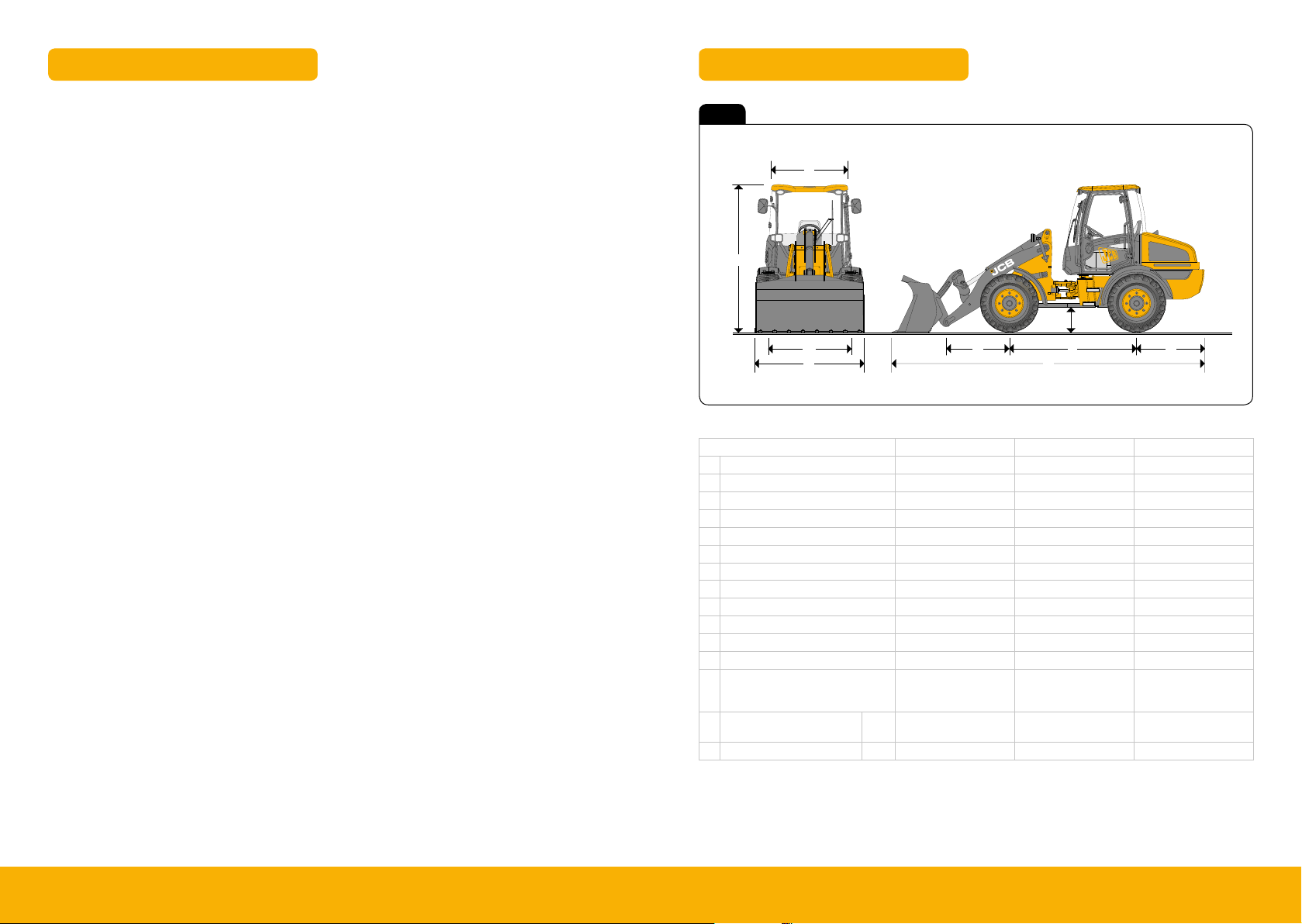
Fig 1
F
J
E
H
G
B
C
A
D
Machine model 406 407 409
A Overall length mm 5133 5133 5465
B Axle to pivot pin mm 906 906 1130
C Wheelbase mm 2100 2100 2205
D Axle to counterweight face mm 1268 1268 1295
E Ground clearance mm 313 313 472
F Width over cab mm 1468 1468 1468
G Width over tyres mm 1727 1727 1898
H Wheel track mm 1390 1390 1490
J Height over cab mm 2500 2500 2643
Front axle weight kg 1475 1395 1850
Rear axle weight kg 3398 3668 4076
Total weight kg 4873 5063 5926
Engine
Mechanical 36kW
(49hP)
Transmission Hydrostatic 2 Speed Hydrostatic 2 Speed
JCB Kohler
JCB Kohler
Mechanical 48kW
(64hP)
JCB Kohler
Mechanical 55.4kW
(74hP)
Hydrostatic 2 Speed
(Option 3 speed)
Axles Dana III Dana III Dana III
45Please see operator manual for full details.
406, 407 & 409
Page 4
Dimensions Dimensions
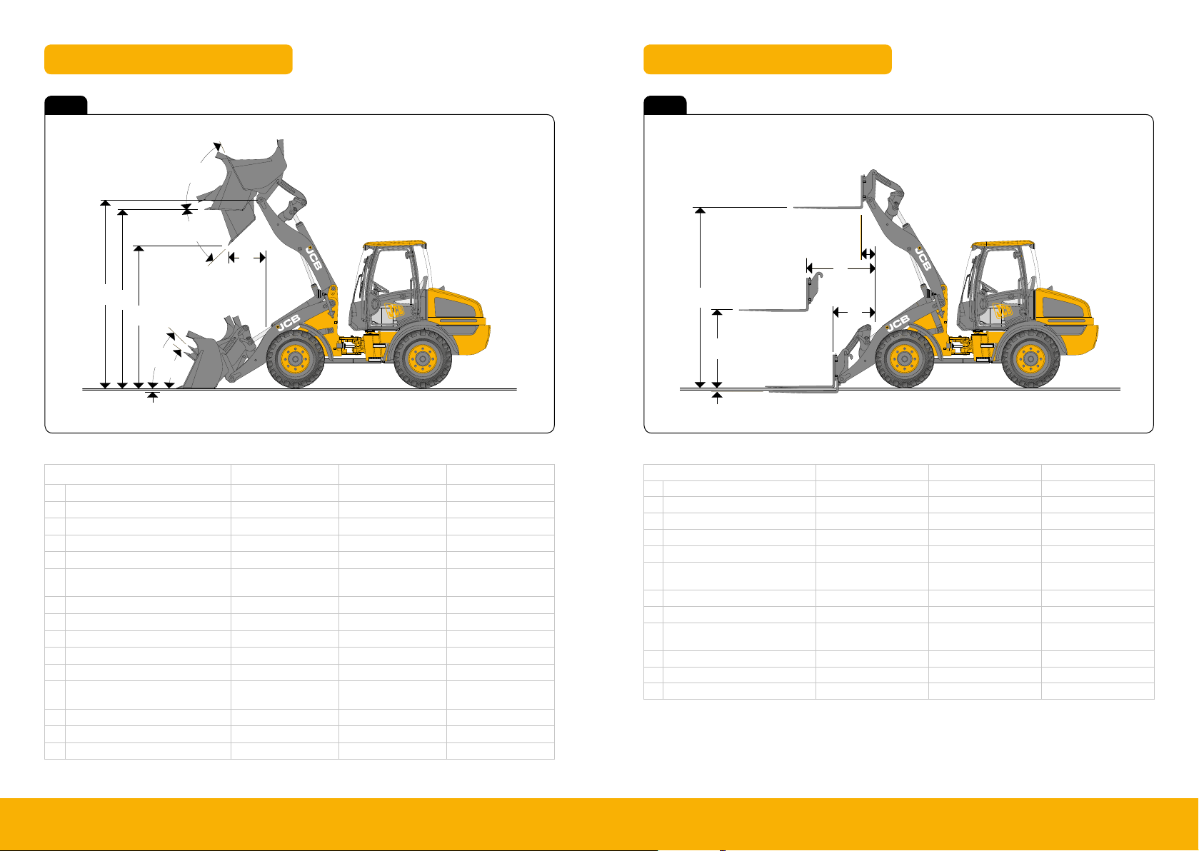
Fig 2 Fig 3
N
M
T
V
Q
R
O
P
S
Machine model 406 407 409
M Dump angle maximum degrees 45 45 45
N Roll back angle full height degrees 56 56 63.6
O Roll back at carry degrees 54 54 53.1
P Roll back at ground level degrees 42 42 41
Q Load over height mm 2991 2991 3189
Dump height
R
(45 deg dump)
S Dig depth mm 105 105 60
T Reach at dump height mm 764 835 599
V
Pin height mm 3120 3120 3340
Bucket type General purpose General purpose General purpose
Bucket equipment Teeth or toeplate Teeth or toeplate Teeth or toeplate
Bucket capacity
(SAE heaped)
Bucket weight kg 287 322 358
Tipping load straight kg 4225 4245 4503
Tipping load full turn kg 3250 3265 3584
mm 2489 2418 2552
m³ 0.8 1 1.2
F
B
E
A
D
C
Machine model
A Reach at ground level mm 710 710 724
B Reach at arms horizontal mm 1232 1232 1187
C Below ground level mm 84 84 17
D Arms, horizontal height mm 1426 1426 1396
E Arms, max. height mm 3012 3012 3231
Reach at
F
maximum height
Payload* kg 2033 2142 2366
Tipping load straight kg 3184 3324 3787
Tipping load full turn
(40°)
Attachment weight kg 191 191 191
Fork carriage width mm 1345 1345 1345
Length of tines mm 1200 1200 1200
* At the centre of gravity distance 500mm. Based on 80% of FTTL as defined in IS0 8313.
** FFTL from Calculation may vary after test work
Manual fork spacings at 50mm increments. Fork section 100mm x 50mm.
mm
kg
406 407 409
506 506 231
2541 2600 2907
67Please see operator manual for full details.
406, 407 & 409
Page 5
Machine Transport Proceedure
Operation
Lifting a Machine
Operation
Transporting The Machine
Operation
Transporting The Machine
T070350-27
Fig 78. Front Axle
F
F
Operation
Transporting The Machine
T070350-27
Fig 78. Front Axle
T070350-28
Fig 79. Rear Axle
F
F
F
F
Operation
Transporting The Machine
A
A
C
D
Operation
Transporting The Machine
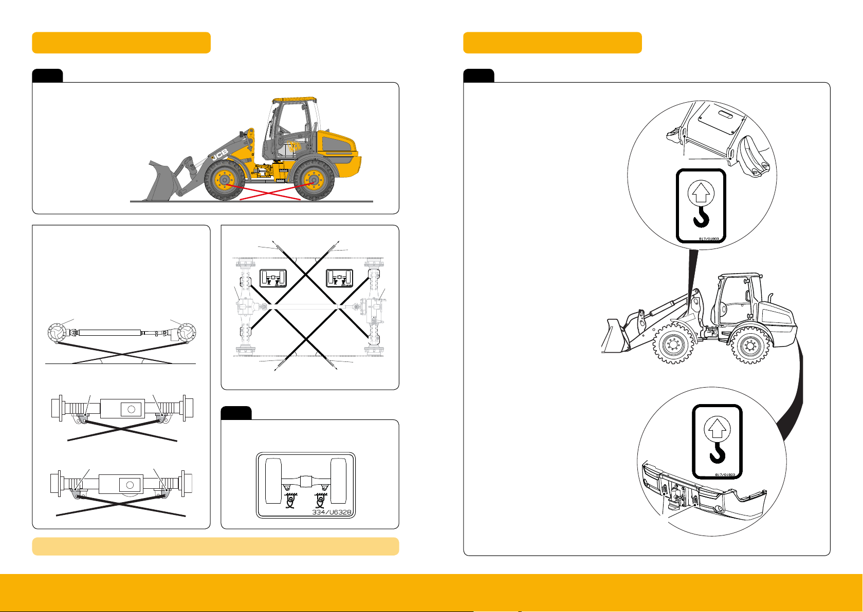
Lifting Points
Fig 4
Note: These Measurements are based on
a 2500mm wide trailer bed. The correc t Tie
down points are Identified by their Labels.
A Restraint Angular Range 8° to 11°
B Restraint Angular Range 40° to 50°
C Front axle
D Rear axle
E Tie Down Restraint
F Tie Down Point
C
A
D
A
Fig 6
To Lift the Machine
All attachments need to be removed
1.
2. Lower Boom
3. Remove all loose Items from machine
4. Check Un-laden weight
A
5. Use ONLY indicated Lift points (A)
6. Ensure the machine Is Balanced.
E
B
B
C
E
B B
E
D
E
Front Axle
F
F
Rear Axle
F
F
REFER TO OPER ATORS MANUAL TRANSPORTING MACHINE
89Please see operator manual for full details.
Fig 5
Tie Down Point Decal
A
406, 407 & 409
Page 6
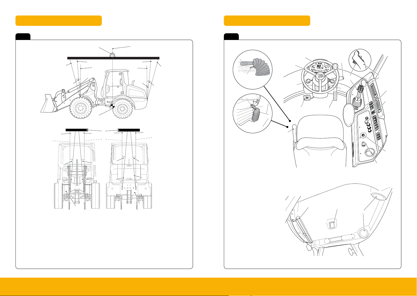
Lifting Points Cab Layout
Operation
Lifting a Machine
B
H
Operation
Lifting a Machine
T070350-31
Fig 84. Lifting (Side View)
B
C
C
P
P
F
G
P
P
E
D
A
H
Operation
Cab Layout
Operation
Cab Layout
Cab Layout
Operation
Drive Controls, Switches and Instruments
Park Brake Lever - 406 and 407 Machines Only
Important: No attempt must be made to adjust the park
brake using the lever handle. The handle adjustment must
remain permanently screwed all the way in.
1 Use this lever to engage the park brake 5 before
leaving the machine. K
Fig32.(T 42)
Park Brake Lever - 407HS and 409 Machines Only
1 You must apply the park brake C before you leave the
cab. K
Fig32.(T 42).
A
B
C
D
Operation
Drive Controls, Switches and Instruments
cab. K
Fig32.(T 42).
C
D
Fig 7 Fig 8
A
P
E
N
J
K
P
L
A H beam lifting spreader
B Centre line - centre of gravity
C Centre line - machine lifting point
D Lifting chain 5° minimum angle
E Lifting Chain 15° maximum angle
F Lifting chain 5° minimum angle
(To avoid damaging the machine)
G Lifting chain 15° Maximum angle
1011Please see operator manual for full details.
P
D
P
C
C
F
A
N
K
P
N
J
K
P
K
P
M
H Centre of gravity (For illustration only -
the position on your machine may var y)
J 0° angle maximum (Not shown)
K 5° Maximum angle
L Front of machine
M Rear of machine
N Perpendicular line - machine lifting point
P Lifting chain
6
21
20
A
P
406 & 407
G
1
12
B
a
%
45
e
15
Aux
1
b
rpm
1870
d
09876.4
mph
26.5
c
121314
17
1
4
23
8
5
6
7
9
13
C
16
18
19
11
10
4
17
8
7
10
3
2
409 O N LY
N
J
5
1. Steering Wheel
2. Accelerator pedal
9
3. Foot Brake
4. Forward/ Reverse Switch
11
5. Park Brake Lever
6. Instrument Cluster
7. Right Hand console
8. Operating Levers
9. Ignition Switch
10. Creep Speed
11. Rotary Throttle (Option)
16
14
15
12. Horn
13. Multi Purpose Steering
Column Switch
14. CAB Interior Light
15. Speakers
16. Front Window Blind
17. Steering column Adjustment.
406, 407 & 409
Page 7

Cab Console Front – 406 Cab Console Front – 407 & 409
Operation
Drive Controls, Switches and Instruments
Operation
Drive Controls, Switches and Instruments
Fig 9 Fig 10
406
22
21
13 15 17
12 14 16 18 19 20
31 2 84 5 6 7 9 10
1. Engine coolant temperature.
2. Engine Air Filter
3. Transmission oil Temperature
4. Transmission Error/Fault
5. High Speed Roading
6. Operator out of seat
7. Trailer Direction indicators
8. Rear Fog Light
9. SRS If fitted
10. High Speed Warning
11. Reverse Warning Light
12. Battery /Alternator no charge
23
11
13. Engine Oil Pressure
14. Water in fuel
15. Engine Pre-heat
16. Hour meter
17. Main Beam
18. Park Brake
19. Low speed warning
20. Forward direction Warning
21. Fuel Level
22. Direction Indicators
23. Hazard Warning
407 & 409
20
B
15
13
12
1
Bat tery/ Alternator No Charge
1.
14
2 3
d
c
26.5
4
2. Transmission Error/Fault (High Speed only)
/Transmission Error Faults (Non High speed)
3. Transmission oil Temperature
4. Park Brake
5. Engine ECU Fault/ Stop
6. Engine Pre-Heat
7. Engine Fault
8. Engine Oil Pressure
9. Engine Air Filter
10. Water In Fuel
11. Smooth Ride system
12. Hydraulic Error/Fault
A
Aux
1
rpm
1870
09876.4
mph
b
5
6
8
7
13. Transmission oil Pressure
14. Foot Brake
15. Fuel Level
16. Engine Coolant Temperature
17. Rear Fog Light
18. Main Beam
19. Trailer Direction Indicators
20. Direction Indicators
21. Hazard warning
A LCD Display
B Fuel Level Gauge
C Engine Temperature Gauge
21
C
16
a
18
17
10
9
19
11
1213Please see operator manual for full details.
406, 407 & 409
Page 8

Switching Options Start Up Sequence
Operation
Cab Layout
Operation
Cab Layout
Cab Layout
Joys tick
Is olation
Gear Chang eSw itch
(High S peed)
Operation
Seat Belts
described.
tug. The seat belt should 'lock'.
!MWARNING
Operation
Starting The Engine
2 Press the MD button.
3 Enter your six digit master code using the keypad and
then press the ENT button.
4 The LED will flash three times to indicate acceptance
of the code.
5 Within 59 seconds of the three flashes press the MD
button.
6 Enter your four digit PIN number using the keypad
and then press the ENT button.The LED will flash four
Operation
Drive Controls, Switches and Instruments
Constant Flow Switches
Constant Flow
K
Right Console Switches ( T 51)
Setting the constant flow to ON gives constant forward flow
only. “Aux 2 “ and the padlock symbol will appear on the
dashboard display panel.
The flow can be stopped momentarily by operating the
right side roller switch on the joystick.
To stop the constant flow, set the constant flow switch to
OF F.
Note: The engine will not crank with the constant flow
switch set to ON.
Constant Flow with High Flow (If Fitted)
K
Right Console Switches ( T 51)
High flow gives constant high flow and will only work when
the constant flow switch is set to ON.
To stop the high flow, set the high flow or the Aux 2 switch
to OFF.
Note: If the pressure gets too high in the system, the high
flow will turn off automatically.
Auxiliary Power Socket
The socket can provide a 12V DC power supply (from the
battery) to an electrical accessory.
Only connect an electrical accessory which is compatible
with the power rating of the socket. The limits for the circuit
are 7.5A continuous with an intermittent 10A.
Always run the engine during the prolonged use of an
electrical accessory, otherwise the battery can discharge.
Operation
Starting The Engine
To Add a New or Additional Starter key
Note: Starter keys can be programmed to start more than
one machine.
1 Put the master key in the starter switch then turn the
starter switch to position I. The LED will flash 3 times.
2 Turn the starter switch to position 0 then remove the
master key.
3 Put a new or an additional starter key in the starter
switch then turn the starter switch to position I. The
LED will flash 4 times to confirm the starter key has
been added.
Operation
Drive Controls, Switches and Instruments
Right Console Switches
Joystick Isolation (if fitted)
Two position rocker switch with backlight.
The switch functions operate when the
starter switch is in the ON position.
Position 1: OFF (Backlight OFF)
Position 2: ON (Backlight ON)
Rear Fog Light (if fitted)
340051-1
Three position self-centring rocker
switch. The switch functions only operate
when the starter switch and the Side
Lights and Headlights switch are in the
ON position 2.
Position 1: OFF (Light-bar OFF)
Position 3: Default (Light-bar OFF)
Position 2: ON (Light-bar ON)
Operation
Drive Controls, Switches and Instruments
Cab Interior Light
T2-020
Press either end of the light unit A to switch on the cab
interior light. Pressing the other end will switch the light off.
Make sure the light is turned off when you intend to leave
the machine for a long period of time.
C007130-1
Fig 41.
Front Work Light (if fitted)
340100-1
Two position rocker switch. The switch
functions operate when the starter switch
is in the ON position.
Position 1: OFF (Light-bar OFF)
Position 2: Work Light ON (Light-bar ON)
Front and Rear Work Lights (if fitted)
333-L2606
Three position rocker switch. The switch
functions operate when the starter switch
is in the ON position.
Position 1: OFF (Light-bar OFF)
Position 2: ON (Light-bar ON) Front
worklight.
Position 3: ON (Light-bar ON) Front and
rear worklights.
Note: The work lights operate independently of the main
lights circuit.
Beacon
Two position rocker switch. The switch
functions operate when the starter switch
is in the ON or OFF positions.
Position 1: OFF (Light-bar OFF)
Position 2: ON (Light-bar ON)
Roof
Fig 11
Front Work Ligh t
Rear Auxiliary
Right Hand Console
Fig 12
Q-Hitc h Locking
Pin Isolat or
Joystick Isolation
Constan t Flow
Selector
1415Please see operator manual for full details.
Front & Rear
Work Lights
Flashing B eacon
Rear Wipe r Side l ights &
Gear Cha nge Switch
(High Spee d)
Constan t Flow
Selecto r High Flow
Rear Fog Lig ht 2 Speed
Headlights
Hazard L ights
Smooth Ri de
System
(Creep Spe ed Option)
16
14
15
6
1
12
5
20
A
B
e
15
Aux
1870
d
09876.4
mph
26.5
1213141718
1
4
23
5
6
3
13
21
C
a
%
45
16
1
b
rpm
c
19
11
10
8
7
9
4
17
2
8
11
7
10
9
1
Insert Isolator Key
Isolator Key Located either outside
or Under Bonnet.
3
Key on & Dis Arm Immobiliser
Coded Key (Option) or Key Pad.
See Immobiliser Section
5
Start Machine
Turn Key though to position S once started key
will spring Back to IGN position.
2
Apply Seat Belt, Check Neutral Controls
Check all Levers are in neutral position
and fasten seatbelt.
4
Engine Pre- Heat
Hold key in Position 1 for approximately
2-3 Secs and then start.
6
Activate Controls & Beacon
Independent
Beacon switch.
Press Isolator switch
to activate Controls.
406, 407 & 409
Page 9

Fig 35. ( T 46).
– Forward, push the switch forward.
– Reverse, pull the switch back.
– Neutral, put the switch in its central position.
direction. K
Fig35.(T 46).
!MCAUTION
C051330-C4
Fig 37.
Tabl e 1.
Note: See the joystick operation decal fitted to your
machine.
Rotary Throttle Control (Option)
!MWARNING
C Tortoise - Used for low speed
operations (for example loading).
Push the button to select this mode.
The hare icon will go OFF and the
tortoise icon (on the front console) will
come ON.
D Hare - Used for high speed operations
(for example roading). Push the
button to select this mode. The hare
icon on the front console will come
ON.
D
C
Operation
D
C
Operation
Drive Controls, Switches and Instruments
SW-001_2
Machine Operation
Operation
Drive Controls, Switches and Instruments
+
-
A
Directional Control on Main Joystick
Fig 13
A Direction Switch
B Horn
C Tortoise Switch
D Hare switch.
B
Creep Speed
Fig 14
1. Select Creep Speed.
2. Select Forward drive.
3. Adjust Road speed adjust Knob A.
4. To Lock Setting Turn thumb wheel below
clockwise, to unlock turn counter clockwise.
High Road Speed (option)
Fig 15
1. Travel in Hare mode approximately 6-20 kph.
When display shows “+” High speed can
be selected.
2. Push the gear change switch and High speed
will be selected. Highway Icon shows on dash
3. Machine is in High speed until deselected.
1617Please see operator manual for full details.
To change Back to Hare Mode
1. Travel at 6-10 KPH. The “-” symbol will
display adjacent to motorway symbol.
2. When the Gear change Icon is “On”
push the switch to engage Hare speed.
406, 407 & 409
Page 10

Machine Operation
Operation
Operating Levers
Control Lever Functions
Overview
The information label is adjacent to the servo-control lever
and gives an overview of its functions. The label
information depends on the specification of your machine.
K
Fig50.(T 67), K Fig51.(T 67), K Servo Controls
Decal ( T 68) and K Servo Controls Decal With
Differential Lock ( T
68).
Note: Button C is a machine option and the logo will only
be shown on the decal if the diff lock is fitted.
K
Differential Lock (If Fitted). ( T 47).
Manual Control Machines (406 and 407)
T070350-47B
Fig 51. Manual Controls Decal With Differential Lock
Table 3. Manual Controls
AA
B
G
G
A Single spool control configuration
B Twin Spool Control Configuration
C Single spool configuration with optional
locking differential.
D Twin spool configuration with optional locking
differential.
E Machine Option (Diff Lock) K
Differential
Lock (If Fitted). ( T 47)
F Tortoise / Hare Speed Range Switches
K Speed Switches ( T 47)
E
E
F
F
J
J
G
G
C
D
H
Operation
Operating Levers
Servo Control Machines (Optional 407 and 409)
Table 4. Servo Controls
A
B
H
A Single spool control configuration
B Twin Spool Control Configuration
C Single spool configuration with optional
locking differential.
D Twin spool configuration with optional locking
differential.
E Machine Option (Diff Lock) K
Differential
Lock (If Fitted). ( T 47)
F Tortoise / Hare Speed Range Switches
K Speed Switches ( T 47)
G Spool Control (First Auxiliary Spool)
H Spool Control (Second Auxiliary Spool - If
Fitted)
J Control Lever
Operation
Operating Levers
Servo Control Machines (Optional 407 and 409)
T070350-48A
Fig 52. Servo Controls Decal
Table 4. Servo Controls
A
B
F
F
G
G
H
J
J
C
H
A Single spool control configuration
B Twin Spool Control Configuration
C Single spool configuration with optional
locking differential.
D Twin spool configuration with optional locking
differential.
E Machine Option (Diff Lock) K
Differential
Lock (If Fitted). ( T 47)
F Tortoise / Hare Speed Range Switches
K Speed Switches ( T 47)
G Spool Control (First Auxiliary Spool)
H Spool Control (Second Auxiliary Spool - If
Fitted)
J Control Lever
Operation
Operating Levers
G
G
C
D
Operation
Operating Levers
Operation
Operating Levers
Fig 16 Fig 18
406
J
F
J
F
H
Manual Controls Decal
A Single Spool Control Configuration
B Twin Spool Control Configuration
C Single Spool configuration with optional
Locking differential.
D Twin Spool configuration with optional
Locking differential.
Fig 17
407 & 409
J
A Single Spool Control Configuration
B Twin Spool Control Configuration
C Single Spool configuration with optional
Locking differential.
D Twin Spool configuration with optional
Locking differential.
F
G
Servo Controls Decal Servo Controls Decal With Differential Lock
G
J
1819Please see operator manual for full details.
F
E
J
F
H
E
J
Manual Controls Decal With Differential Lock
E Machine Option (Diff lock)
F Tortoise/Hare Speed Range switches
G Spool Control
H Spool Control (Second Aux)
J Control Lever.
F
G
J
E
F
G
J
E Machine Option (Diff lock)
F Tortoise/Hare Speed Range switches
G Spool Control
H Spool Control (Second Aux)
J Control Lever.
D
F
1.
Arm Raise
2. Arm Lower
3. “Float”
4. Empty “Dump”
5. Fill “Crowd”
E
CAUTION:
Do not use the ‘float function’
as a return to ground Detent.
This can Cause Damage to
Machine, cause instability
-
and Injury to the Operator.
406, 407 & 409
Page 11

Fig 130. ( T 190).
T070350-21
Fig 131. Auxiliary Lever (If fitted)
T070350-23
Fig 132. Servo Control Lever (If fitted)
D
F
H
Optional Attachments
Quickhitch Control
806070-6
Fig 126.
T070350-21
Fig 127. Auxiliary Lever (If fitted)
T070350-22
Fig 128. Servo Control Lever (If fitted)
B
A
C
D
F
H
Optional Attachments
Quickhitch Control
806070-6
Fig 126.
B
A
C
D
Optional Attachments
Quickhitch Control
806070-6
Fig 126.
T070350-21
B
A
C
D
F
Operation
Drive Controls, Switches and Instruments
leaving the machine. K
Fig32.(T 42)
Park Brake Lever - 407HS and 409 Machines Only
1 You must apply the park brake C before you leave the
cab. K
Fig32.(T 42).
A
B
C
D
Operation
Entering and Leaving the Cab
Operation
Operation
Entering and Leaving the Cab
Operation
Operation
Operating Levers
Operation
Starting The Engine
To Add a New or Additional Starter key
Note: Starter keys can be programmed to start more than
one machine.
1 Put the master key in the starter switch then turn the
starter switch to position I. The LED will flash 3 times.
2 Turn the starter switch to position 0 then remove the
master key.
3 Put a new or an additional starter key in the starter
switch then turn the starter switch to position I. The
LED will flash 4 times to confirm the starter key has
been added.
Machine Operation – Q-Hitch Shut Down Sequence
Fig 19 Fig 21
Press and hold Q-hitch Switch
and activate to “Unlock hitch”
and release.
Q-Hitc h Locking
Pin Isolat or
Locate Pin A into attachment and raise slightly.
Then Crowd attachment onto Hitch Ensuring
good location of Pin C into D.
F
1
Stop Machine
Park machine on dry Level ground.
2
Apply Park Brake, Check Neutral
Bring the machine to a safe stop. Apply Hand
brake and place transmission in Neutral.
A
C
Fig 20 Fig 22
Operate Aux service to “lock on” attachment.
Test attachment is mated to machine.
H
2021Please see operator manual for full details.
Servo Control Lever (If fitted)
B
Auxiliary Lever (If fitted)
It is the responsibilit y of the operator to make sure
the machine is lef t in a safe & secure environment.
3
Lower Arm / Attachment
Place Bucket/Attachment on ground
and Isolate controls.
407 & 409
4
Key off & Remove
Turn Engine off, Turn to IGN on and Vent
Hydraulic system.
If Attachment requires Hydraulics coupling,
Lower attachment to ground level. Turn off
engine and vent Hydraulic system. Connect
couplings and route hoses safely, ensuring
Connectors are cleaned and secure.
J
5
Exit machine and Secure
Using 3 points of contact and then lock Door.
6
Remove Isolator Key
Isolator Key Located either outside
or Under Bonnet.
406, 407 & 409
Page 12

Maintenance Position
Routine Maintenance
Prepare the Machine for Maintenance
Routine Maintenance
Prepare the Machine for Maintenance
Service/Maintenance
Fig 23
Machine Maintenance should be carried out by trained and qualified personnel.
Ensure the machine is parked safe level ground and Isolated.
Daily Checks (10h) Checks
Condition of attachment / optional equipment Visual
Grease as required all points on machine (ref Operator handbook) Physical
Check machine condition latches bonnets, Visual / physical
Check in Cab switches and functions Visual/physical
Check engine bay Visual
Check engine oil Physical
Check hydraulic oil (sight glass) Visual
Check coolant levels Visual
Check fuel separator (Drain if necessar y) Visual / physical
Check coolant pack for dust debris Visual / physical
Check windscreen & washers fluid level Visual / physical
Check operation of all services Physical
Check operation of key items horn lights beacon Visual / audible
Check operation of hour meter, Visual
Check tyres and pressures Visual / physical
Weekly Checks (50h) Check
Grease machine where necessar y Physical or Visual
Check tyres and tread Visual
Check machine hose and pipework Visual
Check ram condition Visual
1. Park machine In Either position A or B depending on task (position B requires safety strut).
2. Isolate and Vent machine, removing Key and Isolator.
2223Please see operator manual for full details.
406, 407 & 409
Page 13

Routine Maintenance
Electrical System
B
A
Routine Maintenance
Access Panels
Access Panels
T3-100
Important: Before you stop the engine, you must allow the
engine to operate at low idle for four minutes. The delay
allows the coolant temperatures to stabilise before you
open the engine cover.
1 Make the machine safe with the loader arm lowered.
Refer to Prepare the Machine for Maintenance.
2 Unlock the security lock built into the release button
A. It is recommended that the cover is kept locked.
3 Press in the release button and allow the gas struts to
raise the cover.
Note: Your machine may differ slightly from that shown.
Closing the Engine Cover
1 Pull down the engine cover until the latch engages.
2 Make sure the cover is securely latched.
3 Lock the security lock and remove the key.
Access Covers
Routine Maintenance
Engine
A
Routine Maintenance
Engine
Cleaning the Air Filter Dust Valve (407 & 409
Machines)
Important: Do not run the engine with the dust valve K
removed. K
Fig117.(T 167).
1 Make the machine safe with the loader arm lowered.
Refer to Prepare the Machine for Maintenance.
2 Open the engine cover.
3 Check the dust valve K is not blocked.
4 Inspect the rubber flaps for cuts and nicks and check
that the rubber is not perished. Renew if necessary.
5 Make sure that the air holes L are clear.
6 Close the engine cover.
L
K
Routine Maintenance
Engine
Routine Maintenance
Electrical System
Engine cover
Fig 24 Fig 29Fig 26
A Key lock (ignition key)
Hydraulic Oil & Washer Bottle
Fig 25
A Sight glass
B Hydraulic Oil Filler cap
C Washer Filler
A
B
A
Fig 27
Fig 28
A Air Filter
B Fuel Filter
A
Secondary Fuses
and relays location
A Relays
B Secondary
Fuses
Coolant
A Filler
HOT
MAX
Engine Oil
A Engine Oil Dipstick
B Engine Oil Filler
B
B
Fig
26
Fig
Fig
29
27
A
2425Please see operator manual for full details.
COLD
C
MIN
Fig
28
406, 407 & 409
Page 14

Fluids and Lubricants Machine Attachments
Item
Fuel Tank 80 (17.6) Diesel
Engine (Oil) 406 Machines Only 4001/18 0 5 20 litres
Minimumw 11 (2.42)
Maximum 12 (2.64)
Engine (Oil) 407&409 Machines Only 4001/3005 20 litres
Minimum 11 (2.42)
Maximum 12 (2.64)
Front Axle
(Includes Hubs)
Rear Axle
(includes Hubs)
Hydraulic System 70 (15.4) JCB Hydraulic Fluid HP15 4002/0503 20 litres
Capacity
Litre (UK Gal)
4.4 (0.96) JCB Gear Oil HP 4000/0505 20 litres
6.05 (1.33) JCB Gear Oil HP 4000/0506 20 litres
Fluid / Lubricant
JCB Extreme Per formance
15W 40 (API CJ14,ACEA
E6-E9,Low SAPS) Caution Do
not use ordinary engine Oil
JCB Extreme Per formance
10W 40 (API CJ14,ACEA
E6-E9,Low SAPS) Caution Do
not use ordinary engine Oil
JCB Part
Number
Container
Size
Description Weight (kg) Intended Use
Q hitch
Shovel (406)
0.8 Cu metre 287 GP shovel
1.0 Cu metre 332 GP shovel
1.2 Cu metre 353 GP shovel
6 in 1 Cu metre 435 GP shovel
Q hitch forks 191 Unloading and movement
Shovel (407 & 409) GP shovel
0.8 Cu metre 287 GP shovel
1.2 Cu metre 353 GP shovel
1.4 Cu metre 384 GP shovel
To assist multi
attachment users
Hyrdaulic
Requirements
Aux flow
Inching system
Grease points
Electrical Connections
Part of
Braking system
JCB Hydraulic Fluid HP15 4002/0503 5 litres
JCB Special HP grease or
JCB Special MPL-EP Grease
To Prevent corrosion and
moisture, Put Layer of
petroleum jelly on all exposed
2627Please see operator manual for full details.
6 in 1 Cu metre 435 GP shovel
4000/2505
4002/0503
connections
ATTACHMENT WEIGHTS ARE A GUIDE ONLY, ALWAYS CHECK YOUR OWN ATTACHMENTS
406, 407 & 409
Page 15

Troubleshooting/FAQs Your Notes
Issue / FAQ Resolution/Answer
Machine will not start
Machine Hydraulics will not operate
Code not excepted by immobiliser
Coded Key does not work
Qhitch does not unlock
Quick release couplings
do not engage
Ensure all functions are in neutral, High flow is not engaged
and Hand brake is applied before starting.
Ensure Engine is running, Hydraulics have been
activated using the Isolation switch.
Joystick Isolation
Ensure code is current and entered correctly, Be sure sequence
is followed If locked out turn on ignition and leave for 15 minutes
the system will reset to try again with current codes
Ensure the key has not been near electrical items
The coded key is up to date
Use Coded key to re-programme extra keys
Check Machine battery has charge to turn machine over.
Check the Q hitch activation switch
Ensure Hydraulics are active
Check locking pins are free from debris and can mve freely check
electrical connections
Check all pressure has been vented from Machine
Check all pressure has been vented from attachment
(over time attachments can creep) please store all attachments
in the closed position.
Check coupling are free from contamination and dirt
Ensure Hand brake has been released
Machine will not drive
Check speed setting (start in Turtle)
If engaging motorway mode be sure to follow procedure safely
and seatbelt fastened.
2829Please see operator manual for full details.
406, 407 & 409
Page 16

Your NotesYour Notes
3031Please see operator manual for full details.
406, 407 & 409
Page 17

JCB Sales Limited, Rocester, Staffordshire, United K ingdom ST14 5JP
Tel: +44 1889 590312 Email: salesinfo@jcb.com
Download the very latest information on this product range at: www.jcb.com
All right s reserved. No p art of this pub lication may be rep roduced, stored i n a retrieval sys tem, or transmi tted in any form or by any other means, el ectronic, mech anical, photoco pying
or other wise, without p rior permissi on from JCB Sales . All references in t his publicati on to operating wei ghts, sizes, capa cities and other performance m easurements a re provided
for guida nce only and may var y dependant upo n the exact spec ification of the machine. They shou ld not therefore b e relied upon in rel ation to suitab ility for a par ticular applic ation.
Guidance and advice shoul d always be sought f rom your JCB Deale r’. JCB reserves the r ight to change spec ifications wit hout notice. Ill ustrations an d specificatio ns shown may
include op tional equipm ent and accessori es.
9818/290 0
 Loading...