

Page 1

Service
Manual
Fastrac
3170, 3170 Plus
3190, 3190 Plus
3200, 3200 Plus
3220, 3220 Plus
3230, 3230 Plus
Published by the
TECHNICAL PUBLICATIONS DEPARTMENT
of
JCB SERVICE LTD;
World Parts Centre,
Waterloo Park
Uttoxeter, Staffordshire
ST14 7BS
Publication No. 9803/8030
Issue 9
General Information
1
Care & Safety
2
3
Optional Equipment
A
Body & Framework
B
Electrics
C
Controls
D
Hydraulics
E
Transmission
F
Brakes
G
Steering
H
Suspension
S
Engine
T
Routine Maintenance
Page 2

9803/8030 Issue 1
Introduction
This publication is designed for the benefit of JCB Distributor Service Engineers who are receiving, or have received, training
by JCB Technical Training Department.
These personnel should have a sound knowledge of workshop practice, safety procedures, and general techniques associated
with the maintenance and repair of hydraulic earthmoving equipment.
Renewal of oil seals, gaskets, etc., and any component showing obvious signs of wear or damage is expected as a matter of
course. It is expected that components will be cleaned and lubricated where appropriate, and that any opened hose or pipe
connections will be blanked to prevent excessive loss of hydraulic fluid and ingress of dirt. Finally, please remember above all
else
SAFETY MUST COME FIRST!
The manual is compiled in sections, the first three are numbered and contain information as follows:
1 = General Information - includes torque settings and service tools.
2 = Care & Safety - includes warnings and cautions pertinent to aspects of workshop procedures etc.
3 = Routine Maintenance - includes service schedules and recommended lubricants for the whole machine.
The remaining sections are alphabetically coded and deal with Dismantling, Overhaul etc. of specific components, for
example:
A = Optional Equipment
B = Body & Framework ...etc
The page numbering in each alphabetically coded section is not continuous. This allows for the insertion of new items in later
issues of the manual.
Section contents, technical data, circuit descriptions, operation descriptions etc. are inserted at the beginning of each
alphabetically coded section.
All sections are listed on the front cover; tabbed divider cards align directly with individual sections on the front cover for rapid
reference.
Page cross references are generally made by presenting the subject title printed in bold, followed by the title of the section
containing the subject. For example:
“24 If the axle is still on the machine, fit the brake calipers (see Brake Caliper Removal and Replacement, Section G).”
Note: If only the subject title in bold is given, i.e. no section title, the cross reference is to another part of the same section.
Use the contents list at the beginning of each section to find the exact page number.
Where a torque setting is given as a single figure it may be varied by plus or minus 3%. Torque figures indicated are for dry
threads, hence for lubricated threads may be reduced by one third.
‘Left Hand’ and ‘Right Hand’ are as viewed from the rear of the machine facing forwards.
Page 3

i
Section 1 General Information
9803/8030
Section 1
i
Issue 2*
Contents Page No.
Machine Identification Plate 1 - 1
Typical Vehicle Identification Number (VIN) 1 - 1
Unit Identification 1 - 1
Torque Settings
Introduction - Zinc Plated Fasteners and Dacromet Fasteners 2 - 1
Zinc Plated Fasteners 2 - 2
Dacromet Fasteners 2 - 3
Sealing and Retaining Compounds 3 - 1
Service Tools Numerical List 4 - 1
Service Tools
Optional Equipment 5 - 0
Body and Framework 5 - 1
Electrics 6 - 1
Hydraulics 7 - 1
Transmission 8 - 1
Brakes 9 - 1
Steering 9 - 1
Suspension 9 - 2
Engine 9 - 2
Moving a Disabled Machine
General 10 - 1
Preparation for Towing 10 - 1
Transporting the Machine 10 - 2
*
Page 4
1 - 1
Section 1 General Information
9803/8030
Section 1
1 - 1
Issue 3*
417490
S
P
X
R
M
N
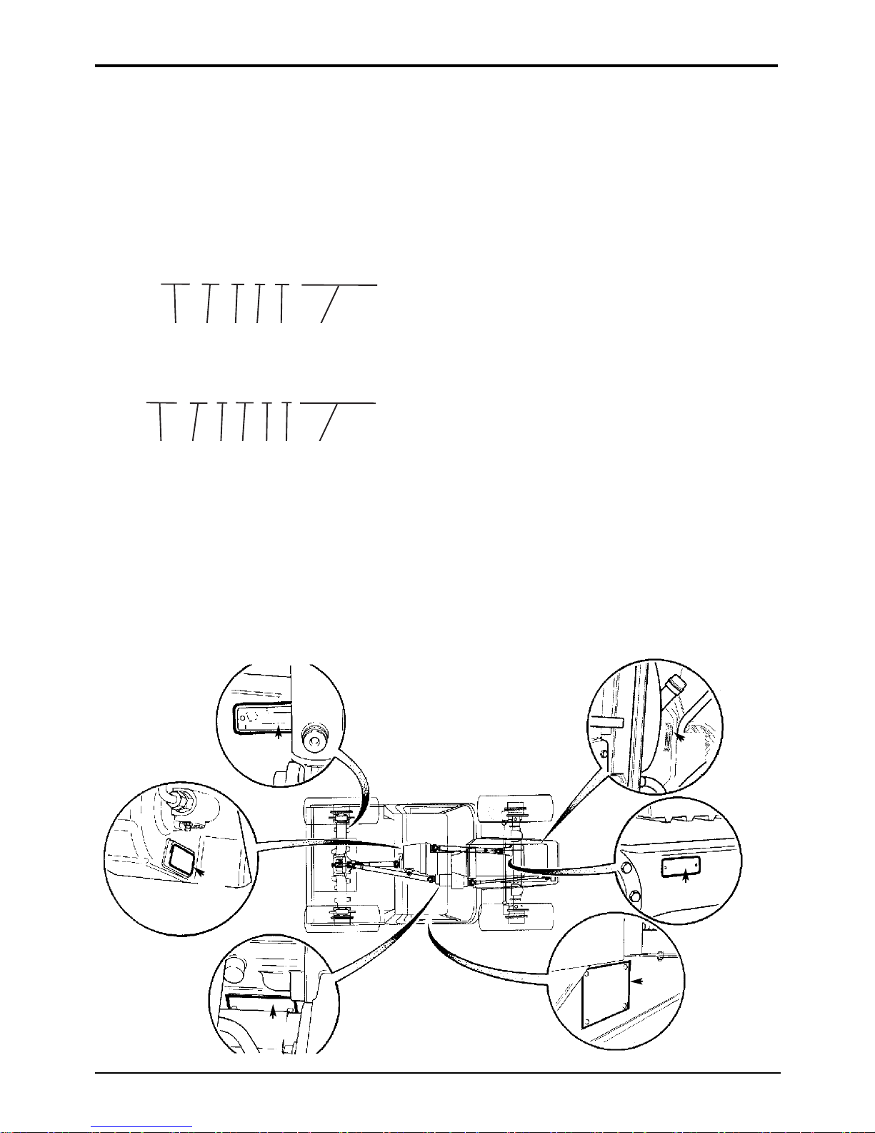
Serial Number Plate
Each machine has a serial number plate located at X. The 17
digit Vehicle Identification Number (VIN), and the serial
numbers of the engine and transmission are stamped on the
plate.
Typical Vehicle Identification No. (VIN)
Original VIN Configuration
Later VIN Configuration
A = Manufacturing Code
B = Machine Range
FT = Fastrac
C = Engine Type
17 = 3190 or 3190 Plus
18 = 3220 or 3220 Plus
19 = 3170 or 3170 Plus
23 = 3200 or 3200 Plus
24 = 3230 or 3230 Plus
D = Transmission Type (Gearbox and axle combination)
3170, 3170 Plus All other machines
A = 75 km/h 8 = Standard (40, 50 or 65 km/h)
B = 65 km/h 9 = High Speed (75 km/h)
D = 50 km/h
E = 40 km/h
E = Vehicle Max. Speed
40 = 40 km/h
50 = 50 km/h
65 = 65 km/h
75 = 75 km/h
F = Serial Number
G = Authenticity Code
H = year Code (e.g. 6 = 2006)
Unit Identification
The serial number of each major unit is also stamped on the
unit itself as shown below. If a major unit is replaced by a
new one, the serial number on the plate will be wrong. Either
stamp the new number of the unit on the identification plate,
or simply stamp out the old number. This will prevent the
wrong unit number being quoted when replacement parts
are ordered.
Engine M
Gearbox Assembly (assembly of all three gearboxes) N
Speed Gearbox P
Front Axle R
Rear Axle S
*
*
SLP FT 17 A 40 XXXXXXX
A B C D E F
JCB 23 8 40 X 6 XXXXXXX
A C D E G H F
*
*
*
Page 5

2 - 1
Section 1 General Information
9803/8030
Section 1
2 - 1
Issue 1
Torque Settings
Introduction - Zinc Plated Fasteners and Dacromet Fasteners
Some external fasteners on Fastrac machines are assembled using an improved type of corrosion resistant finish. This type of
finish is called Dacromet and replaces the original Zinc and Yellow plating used on earlier machines.
The two types of fasteners can be readily identified by colour and part number suffix as follows:
Fastener Type Colour Part Number
Zinc and Yellow Golden finish ‘Z’ (e.g. 1315/3712Z)
Dacromet Mottled silver finish ‘D’ (e.g. 1315/3712D)
Note: As the Dacromet fasteners have a lower torque setting than the Zinc and Yellow fasteners, the torque figures used must
be relevant to the type of fasteners.
Note: A Dacromet bolt should not be used in conjunction with a Zinc and Yellow plated nut, as this could change the torque
characteristics of the torque settings further. For the same reason, a Dacromet nut should not be used in conjunction with a
Zinc and Yellow plated bolt.
Note: All bolts used on JCB machines are high tensile and must not be replaced by bolts of a lesser tensile specification.
Note: Dacromet bolts, due to their high corrosion resistance are used areas where rust could occur. Dacromet bolts are only
used for external applications. They are not used in application such as gearbox and engine joint seams or internal
applications.
Page 6
2 - 2
Section 1 General Information
9803/8030
Section 1
2 - 2
Issue 1
Torque Settings
Zinc Plated Fasteners (golden finish)
Use only where no torque setting is specified in the text. Values are for dry threads and may be within three per cent of the
figures stated. For lubricated threads the values should be REDUCED by one third.
Metric Grade 8.8 Bolts
Bolt size Torque Settings
Dia. (mm) Hexagon Nm kgf m lbf ft
(A/F) mm
M5 (5) 8 7 0.7 5
M6 (6) 10 12 1.2 9
M8 (8) 13 28 3.0 21
M10 (10) 17 56 5.7 42
M12 (12) 19 98 10 72
M16 (16) 24 244 25 180
M18 (18) 27 350 36 258
M20 (20) 30 476 48 352
M24 (24) 36 822 84 607
M30 (30) 46 1633 166 1205
M36 (36) 55 2854 291 2105
Metric Grade 10.9 Bolts
Bolt size Torque Settings
Dia. (mm) Hexagon Nm kgf m lbf ft
(A/F) mm
M6 (6) 8 16 1.6 12
M8 (8) 13 39 4 29
M10 (10) 17 78 8 57
M12 (12) 19 137 14 101
M16 (16) 24 343 35 253
M20 (20) 30 657 67 485
M24 (24) 36 1157 118 853
Hydraulic Hose to Adapter Connections Hydraulic Adapter into Component Connections
with bonded washers
Torque Settings Torque Settings
BSP Size Nm kgf m lbf ft BSP Size Nm kgf m lbf ft
(inches) (inches)
1
/8 14 1.4 10
1
/8 20 2.1 15
1
/
4 24 2.5 18
1
/
4 34 3.4 25
3
/8 33 3.3 24
3
/8 75 7.6 55
1
/2 44 4.8 35
1
/2 102 10.3 75
5
/8 58 6.0 43
5
/8 122 12.4 90
3
/4 84 8.6 62
3
/4 183 18.7 135
1 115 11.8 85 1 203 20.7 150
1
1
/2 244 24.9 180 11/2 305 31 225
Metric - All Internal Hexagon Headed Cap Screws
Diameter Torque
mm Nm kgf m lbf ft
M3 2 0.2 1.5
M4 6 0.6 4.5
M5 11 1.1 8
M6 19 1.9 14
M8 46 4.7 34
M10 91 9.3 67
M12 159 16.2 117
M16 395 40 292
M18 550 56 406
M20 770 79 568
M24 1332 136 983
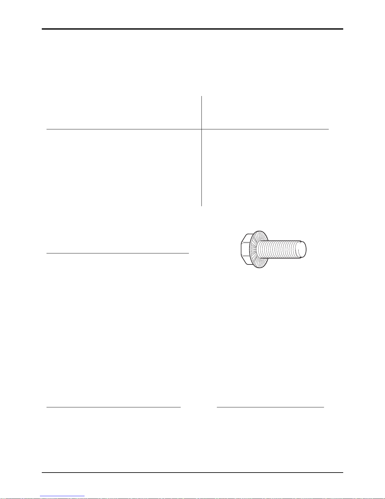
Verbus Ripp Bolts
Torque settings for these bolts are determined by the
application. Refer to the relevant procedure for the
required settings.
A343780
Page 7

2 - 3
Section 1 General Information
9803/8030
Section 1
2 - 3
Issue 1
Torque Settings
Dacromet Fasteners (mottled silver finish)
Use only where no torque setting is specified in the text.
NOTE: DACROMET FASTENERS ARE LUBRICATED AS PART OF THE PLATING PROCESS: DO NOT LUBRICATE.
Metric Grade 8.8 Bolts
Bolt size Torque Settings
Dia. Nm kgf m lbf ft
M6 x 1.0 9 0.9 7
M8 x 1.25 22.5 2.3 17
M10 x 1.5 47.5 4.8 35
M12 x 1.75 80 8.2 59
M14 x 2 133 13.6 98
M16 x 2 200 20.4 148
M18 x 2.5 278 28.4 205
M20 x 2.5 392 40 289
M24 x 3 675 69 498
M30 x 3.5 1348 138 994
Metric Grade 10.9 Bolts
Bolt size Torque Settings
Dia. Nm kgf m lbf ft
M6 x 1.0 13.5 1.4 10
M8 x 1.25 35 3.6 26
M10 x 1.5 62.5 6.4 46
M12 x 1.75 115 11.7 85
M14 x 2 175 17.9 129
M16 x 2 300 30.6 221
M18 x 2.5 395 40 291
M20 x 2.5 559 57 412
M24 x 3 962 98 710
M30 x 3.5 1920 196 1416
Metric Grade 12.9 Bolts
Bolt size Torque Settings
Dia. Nm kgf m lbf ft
M6 x 1.0 15 1.5 11
M8 x 1.25 40 4.1 29
M10 x 1.5 80 8.2 59
M12 x 1.75 133 13.6 98
M14 x 2 225 23 166
M16 x 2 350 35.7 258
M18 x 2.5 463 47 342
M20 x 2.5 654 67 482
M24 x 3 1125 115 830
M30 x 3.5 2247 229 1657
Page 8

Location: Front Lower Crossmember
Nm: 115 kgf m: 12 lbf ft: 85
A401990
2 - 4
Section 1 General Information
9803/8030
Section 1
2 - 4
Issue 2*
Torque Settings
Dacromet Fasteners (mottled silver finish) - List of Torque Settings
This list shows Dacromet fasteners that may not be shown in the other sections of the service manual.
Location: Front Wrapper
(top/bottom)
Nm: 392 kgf m: 40 lbf ft: 289
A402060
Location: Front P.T.O. Box
Nm: 200 kgf m: 20 lbf ft: 148
A402230
Location: Front Axle Upper Arm
Mounting Bracket
8.8 grade bolts:
Nm: 200 kgf m: 20 lbf ft: 148
10.9 grade bolts (all bolts with JCB
Threadlocker and Sealer and with
spacer fitted at bolt B):
Nm: 300 kgf m: 30 lbf ft: 220
Location: Steershaft Bearing
Nm: 28 kgf m: 2.9 lbf ft: 21
Location: Steershaft upper UJ
Nm: 38 kgf m: 3.9 lbf ft: 28
Location: Front Engine Mounting
Nm: 200 kgf m: 20 lbf ft: 148
A402150
Location: Header Tank Clamp Plate
Nm: 30 kgf m: 3 lbf ft: 22
A402290
A402270
B
*
Page 9

Location: Left Hand Pannier Step
Nm: 47.5 kgf m: 4.8 lbf ft: 35
A402200
2 - 5
Section 1 General Information
9803/8030
Section 1
2 - 5
Issue 1
Torque Settings
Dacromet Fasteners (mottled silver finish) - List of Torque Settings (continued)
Location: Lower Link Capscrew
Nm: 654 kgf m: 67 lbf ft: 482
A402140
Location: Tower Casting to Axle
Nm: 392 kgf m: 40 lbf ft: 289
A402010
Location: Rear Lower Crossmember
Nm: 200 kgf m: 20 lbf ft: 148
A402260
Location: Gearbox Crossmember
Nm: 200 kgfm: 20 lbf ft: 148
Location: Rear Anti-Roll bar mounting
bracket
Nm: 392 kgf m: 40 lbf ft: 289
A402120
Location: Rockinger Hitch Bolt
Nm: 392 kgfm: 40 lbf ft: 289
A402030
Location: Rear Crossmember
Nm: 392 kgf m: 40 lbf ft: 289
A402280
Location: Lower Link Bolt (Hex Head)
Nm: 392 kgf m: 40 lbf ft: 289
A402040
Page 10

3 - 1
Section 1 General Information
9803/8030
Section 1
3 - 1
Issue 2*
Sealing and Retaining Compounds
Gasketing - Loctite 509 To seal the joint faces between the PTO/splitter gearbox, the 4102/3202 50ml
speed gearbox and the range gearbox. 4102/3240 315 ml
JCB Multigasket A medium strength sealant suitable for all sizes of gasket
flanges, and for hydraulic fittings of 25-65 mm diameter. 4102/1212
JCB High Strength Threadlocker A high strength locking fluid for use with threaded components. 4102/0551
Gasketing for all sizes of flange where the strength of the joint
is important.
JCB Retainer (High Strength) For all retaining parts which are unlikely to be dismantled. 4101/0651
JCB Threadlocker & Sealer A medium strength locking fluid for sealing and retaining nuts,
bolts, and screws up to 50 mm diameter, and for hydraulic
fittings up to 25 mm diameter. 4101/0251
JCB Threadlocker For threads of suction strainer. 4101/0451 50ml
JCB Threadlocker & Sealer A medium to high strength locking fluid. 4101/0552
(High Strength)
JCB Threadseal Medium strength thread sealant (for patch bolts that are re-used). 4102/1951 50 ml
Clayton System Seal SC1251 A thread sealant used mainly on air brake system hose adapters. 4102/2210 2ml
JCB Activator A cleaning primer which speeds the curing rate of anaerobic 4104/0251 Aerosol
products. 4104/0253 Bottle
JCB Cleaner/Degreaser For degreasing components prior to use of anaerobic adhesives
and sealants. 4104/1557 Aerosol
Direct Glazing Kit For one pane of glass, comprises items marked † below plus
applicator nozzle etc. 993/55700
† Ultra Fast Adhesive For direct glazing 4103/2109 310 ml
† Active Wipe 205 For direct glazing 4104/1203 250 g
4104/1206 30 ml
† Black Primer 206J For direct glazing 4201/4906 30 ml
JCB Clear Silicone Sealant To seal butt jointed glass. Also to seal hub planet gear carrier
when no 'O' ring is fitted 4102/0901
Black Polyurethane Sealant To finish exposed edges of laminated glass 4102/2309 310 ml
*
Page 11

4 - 1
Service Tools Numerical List
Page No.
1370/0901Z Nut M24 9 - 1
1406/0021 Bonded Washer 7 - 1
1604/0006 Adapter 7 - 1
1604/0008 Adapter 7 - 1
1606/0012 Adapter 7 - 1
1606/0015 Adapter 7 - 1
1612/0006 Adapter 7 - 1
4101/0251 JCB Threadlocker and Sealer 3 - 1
4101/0451 JCB Threadlocker 3 - 1
4101/0552 JCB Threadlocker and Sealer
(High Strength) 3 - 1
4101/0651 JCB Retainer (High Strength) 3 - 1
4102/0551 JCB High Strength Threadlocker 3 - 1
4102/0901 JCB Clear Silicone Sealant 3 - 1
4102/1212 JCB Multigasket 3 - 1
4102/1951 JCB Threadseal 3 - 1
4102/2210 Clayton System Seal SC1251 3 - 1
4102/2309 Black Polyurethane Sealant 3 - 1
4103/2109 Ultra Fast Adhesive 3 - 1
4104/0251 JCB Activator (Aerosol) 3 - 1
4104/0253 JCB Activator (Bottle) 3 - 1
4104/1557 JCB Cleaner/Degreaser 3 - 1
4104/1203 Active Wipe 205 (250 g) 3 - 1
4104/1206 Active Wipe 205 (30 ml) 3 - 1
4104/1310 Hand Cleaner 5 - 1
4201/4906 Black Primer 3 - 1
721/00664 Connecting Lead (Wingst) 6 - 2
721/10885 Harness - ABS Diagnostic (J1939) 6 - 1
816/15118 Test Adapter 7 - 1
816/20008 Adapter 7 - 1
816/20013 Adapter 7 - 1
816/55038 Adapter/Test Point 7 - 1
816/55040 Adapter/Test Point 7 - 1
892/00041 Deglazing Tool 9 - 2
892/00078 Connector 7 - 1
892/00137 Micro Bore Hose 7 - 2
892/00174 Measuring Cup 8 - 2
892/00179 Bearing Press 8 - 1
892/00223 Hand Pump 7 - 2
892/00224 Impulse Extractor 8 - 2
892/00225 Adapter for Impulse Extractor 8 - 1
892/00253 Pressure Test Kit 7 - 1
892/00255 Adapter/Test Point 7 - 1
892/00256 Adapter/Test Point 7 - 1
892/00257 Adapter/Test Point 7 - 1
892/00258 Adapter/Test Point 7 - 1
892/00259 Adapter/Test Point 7 - 1
892/00260 Adapter/Test Point 7 - 1
892/00261 Adapter/Test Point 7 - 1
892/00262 Adapter/Test Point 7 - 1 & 7 - 2
892/00263 Adapter/Test Point 7 - 1
892/00264 Adapter/Test Point 7 - 1
892/00265 Adapter/Test Point 7 - 1
892/00268 Flow Monitoring Unit 7 - 1
892/00269 Sensor Head 7 - 1
892/00270 Load Valve 7 - 1
892/00271 Adapter 7 - 1
892/00272 Adapter 7 - 1
892/00273 Sensor Head 7 - 1
892/00274 Adapter 7 - 2
892/00275 Adapter 7 - 1
892/00276 Adapter 7 - 1
892/00277 Adapter 7 - 1
892/00278 Gauge 0 - 40 bar 7 - 2
892/00279 Gauge 0 - 400 bar 7 - 2
892/00281 Avo Meter 6 - 1
892/00282 Shunt 6 - 1
892/00283 Tool Kit Case 6 - 1
892/00284 Digital Tachometer 6 - 1
892/00285 Oil Temperature Probe 6 - 1
892/00286 Surface Temperature Probe 6 - 1
892/00293 Connector Pipe 7 - 1
892/00294 Connector Pipe 7 - 1
892/00298 Fluke Multimeter 6 - 1
892/00311 Brake Test Kit 8 - 4
892/00312 Dummy End Plate 8 - 2
892/00314 Accumulator Adapter 9 - 1
892/00318 Hose and Adapter Kit 7 - 2
892/00333 Heavy Duty Socket, 19 mm A/F 8 - 2
892/00334 Gland Seal Fitting Tool 7 - 2
892/00706 Test Probe 7 - 2
892/00801 Clutch spanner 5 - 3
892/00802 Rotor puller set 5 - 3
892/00803 Rotor installer set 5 - 3
892/00807 Front plate puller 5 - 3
892/00808 Shaft protector 5 - 3
892/00812 Drive Coupling Spanner 8 - 1
892/00817 Heavy Duty Socket, 17 mm A/F 8 - 2
892/00818 Heavy Duty Socket, 22mm A/F 8 - 2
892/00819 Heavy Duty Socket, 15 mm A/F 8 - 2
892/00842 Glass Lifter 5 - 1
892/00843 Folding Stand 5 - 1
892/00844 Long Knife 5 - 2
892/00845 Cartridge Gun 5 - 1
892/00846 Glass Extractor Handles 5 - 2
892/00847 Nylon Spatula 5 - 3
892/00848 Wire Starter 5 - 2
892/00849 Braided Cutting Wire 5 - 2
892/00864 PD 90 Axle Locknut Spanner 8 - 3
892/00871 Frame (Puller Adapter Assembly) 9 - 1
892/00874 Brace (Puller Adapter Assembly) 9 - 1
892/00875 Bar M24 (Puller Adapter Assembly) 9 - 1
892/00876 Block (Puller Adapter Assembly) 9 - 1
892/00892 Speed Gearbox Locking Tool 8 - 3
892/00916 Spring Compressor 8 - 3
892/00918 Setting Tool Kit 8 - 3
892/00945 Sleeve for M30 Pinion 8 - 3
892/01033 Data Link Adapter Kit - ABS 6 - 1
892/01045 Peg Socket - Wet Clutch 8 - 5
892/01046 Mandrel - Wet Clutch 8 - 4
892/01047 Jig - Wet Clutch 8 - 4
892/01048 Clutch Pack Retainer - Wet Clutch
(2 required) 8 - 4
892/01049 Guide Rod - Wet Clutch
(2 required) 8 - 4
892/01050 Mandrel - Wet Clutch 8 - 4
892/01051 Intermediate Gear Retaining Tool -
Wet Clutch Transmission 8 - 4
892/01052 Locking Plate - Wet Clutch
(2 required) 8 - 4
892/01053 Adapter for impulse extractor
(PTO intermediate shaft,
wet clutch transmission) 8 - 2
892/01066 Combination Lead 6 - 2
892/01092 Wheel Hub Service Kit 8 - 5
926/15500 Rubber Spacer Blocks 5 - 3
992/09000 Peg Spanner 5 - 0
992/12300 Mobile Oven 5 - 1
992/12400 Static Oven 5 - 1
Section 1 General Information
9803/8030
Section 1
4 - 1
Issue 4*
*
Page 12

4 - 2
992/12600 Static Oven 5 - 1
992/12800 Cut-out Knife 5 - 2
992/12801 'L' Blades 5 - 2
993/45400 Torque Multiplier 8 - 1
993/55700 Direct Glazing Kit 3 - 1
993/59300 Pressure Test Adapter and Clamp 8 - 2
993/69800 Seal Kit 7 - 1
993/70111 Break-back Torque Wrench 8 - 3
997/11000 Drive Head Setting Bracket 8 - 3
997/11100 Adapter for M24 Pinion 8 - 3
The following parts are replacement items for kits and would
normally be included in the relevant kit numbers.
Replacement items for kit no. 892/00253
892/00201 Gauge 0 - 20 bar 7 - 1
892/00202 Gauge 0 - 40 bar 7 - 1
892/00203 Gauge 0 - 400 bar 7 - 1
892/00254 Hose 7 - 1
Replacement parts for kit no. 892/01092
1315/3414Z Bolt M10x60 8 - 5
1315/3731Z Bolt M16x220 8 - 5
1315/3835Z Bolt M20x300 8 - 5
1370/0301Z Nut M10 8 - 5
1370/0401Z Nut M12 8 - 5
1370/0601Z Nut M16 8 - 5
1370/0701Z Nut M20 8 - 5
1420/0009Z Washer M12 8 - 5
1420/0012Z Washer M20 8 - 5
445/12303 Washer 8 - 5
892/00891 Dolly 8 - 5
917/02800 Bearing 8 - 5
998/10606 Bearing Fitting Tube 8 - 5
998/10607 Inner Bearing Plate 8 - 5
998/10608 Bearing Centre Puller 8 - 5
998/10610 Puller Rod 8 - 5
998/10614 Reaction Tube 8 - 5
998/10615 Wheel Bearing Carrier Puller 8 - 5
998/10616 Puller Handle Nut 8 - 5
998/10623 Puller Beam 8 - 5
998/10624 Modified Wheel Stud 8 - 5
Section 1 General Information
9803/8030
Section 1
4 - 2
Issue 3*
Service Tools Numerical List (continued)
Page No.
*
Page 13

5 - 0
Section 1 General Information
9803/8030
Section 1
5 - 0
Issue 1
Service Tools
Section A - Optional Equipment
1 992/09000 Peg spanner for piston head of front hitch
ram (including 2 pairs of pegs)
2 992/09003 Replacement pegs for 7.5 mm holes
3 992/09004 Replacement pegs for 10 mm holes
197220
892/00334 Gland Seal Fitting Tool
Page 14

5 - 1
Section 1 General Information
9803/8030
Section 1
5 - 1
Issue 1
Service Tools
Section B - Body and Framework
S186240
Hand Cleaner - special blend for the removal of
polyurethane adhesives.
JCB part number - 4104/1310 (454g; 1lb tub)
S186250
12V Mobile Oven - 1 cartridge capacity - required to
pre-heat adhesive prior to use. It is fitted with a male
plug (703/23201) which fits into a female socket
(715/04300).
JCB part number - 992/12300
S186260
240V Static Oven - available with 2 or 6 cartridge
capacity - required to pre-heat adhesive prior to use.
No plug supplied. Note: 110V models available upon
request - contact JCB Technical Service
JCB part number:
992/12400 - 2 cartridge x 240V
992/12600 - 6 cartridge x 240V
S186270
Cartridge Gun - hand operated - essential for the
application of sealants, polyurethane materials etc.
JCB part number - 892/00845
'
S186280
Folding Stand for Holding Glass - essential for
preparing new glass prior to installation.
JCB part number - 892/00843
S186300
Glass Lifter - minimum 2 off - essential for glass
installation, 2 required to handle large panes of glass.
Ensure suction cups are protected from damage during
storage.
JCB part number - 892/00842
Page 15

Service Tools (continued)
Section B - Body and Framework (continued)
S186310
Wire Starter - used to access braided cutting wire
(below) through original polyurethane seal.
JCB part number - 892/00848
S186320
Glass Extractor (Handles) - used with braided cutting
wire (below) to cut out broken glass.
JCB part number - 892/00846
S186330
Braided Cutting Wire - consumable heavy duty
cut-out wire used with the glass extraction tool
(above).
JCB part number - 892/00849 (approx 25m length)
S186340
Cut-out Knife - used to remove broken glass.
JCB part number - 992/12800
'
S186350
'L' Blades - 25mm (1in.) cut - replacement blades for
cut-out knife (above).
JCB part number - 992/12801 (unit quantity = 5 off)
S186360
Long Knife - used to give extended reach for normally
inaccessible areas.
JCB part number - 892/00844
5 - 2
Section 1 General Information
9803/8020
Section 1
5 - 2
Issue 1
Page 16

Service Tools (continued)
Section B - Body and Framework (continued)
S186470
Nylon Spatula - general tool used for smoothing
sealants - also used to re-install glass in rubber glazing
because metal tools will chip the glass edge.
JCB part number - 892/00847
892/00801 Clutch spanner
S200940
for air conditioning compressor
892/00802 Rotor puller set
S200950
for air conditioning compressor
892/00803 Rotor installer set
S200960
for air conditioning compressor
S186550
Rubber Spacer Blocks - used to provide the correct
set clearance between glass edge and cab frame.
JCB part number - 926/15500
(unit quantity = 500 off)
892/00807 Front plate puller
S200970
for air conditioning compressor
892/00808 Shaft protector
S200980
for air conditioning compressor
5 - 3
Section 1 General Information
9803/8030
Section 1
5 - 3
Issue 1
Page 17

Service Tools
Section C - Electrics
6 - 1
Section 1 General Information
9803/8030
Section 1
6 - 1
Issue 2*
188230
Electrical Test Equipment
1 892/00283 Tool Kit Case
2 892/00281 AVO Meter
3 892/00286 Surface Temperature Probe
4 892/00284 Microtach Digital Tachometer
5 892/00282 100 Amp Shunt - open type
6 892/00285 Hydraulic Oil Temperature Probe
7 892/00298 Fluke 85 Multimeter
8
1514131211109
7654321
D
F
AB
C
H
J
E
G
A386040
721/10885 Harness - Diagnostic (J1939)
A360250
892/01033 Data Link Adapter Kit - ABS
Note: Item A of the Data Link Adapter Kit is unsuitable
for use with the Fastrac and must be replaced by the
‘Harness - Diagnostic (J1939)’ shown below.
AA
*
Page 18

6 - 2
Service Tools (continued)
Section C - Electrics (continued)
Section 1 General Information
9803/8030
Section 1
6 - 2
Issue 2*
721/00664 Connecting Lead - Wingst
A406950
892/01066 Combination Lead
(alternative to 721/00664)
*
Page 19

7 - 1
Section 1 General Information
9803/8030
Section 1
7 - 1
Issue 1
Pressure Test Adapters
892/00255 1/4 in BSP x Test Point
892/00256 3/8 in BSP x Test Point
892/00257 1/2 in BSP x Test Point
892/00258 5/8 in BSP x Test Point
816/15118 3/4 in BSP x Test Point
892/00259 1 in BSP x Test Point
892/00260 1.1/4 in BSP x Test Point
892/00261 5/8 in UNF x Test Point
Pressure Test 'T' Adapters
892/00262 1/4 in M BSP x 1/4 in F BSP x Test Point
816/55038 3/8 in M BSP x 3/8 in F BSP x Test Point
816/55040 1/2 in M BSP x 1/2 in F BSP x Test Point
892/00263 5/8 in M BSP x 5/8 in F BSP x Test Point
892/00264 3/4 in M BSP x 3/4 in F BSP x Test Point
892/00265 1 in M BSP x 1 in F BSP x Test Point
Hydraulic Circuit Pressure Test Kit
892/00253 Pressure Test Kit
892/00201 Replacement Gauge 0-20 bar (0-300 lbf/in
2
)
892/00202 Replacement Gauge 0-40 bar (0-600 lbf/in
2
)
892/00203 Replacement Gauge 0-400 bar (0-6000 lbf/in2)
892/00254 Replacement Hose
:993/69800 Seal Kit for 892/00254 (can also be used with
probe 892/00706)
S188130
S188120
S200140
Service Tools
Section E - Hydraulics
Flow Test Equipment
892/00268 Flow Monitoring Unit
892/00269 Sensor Head 0 - 100 l/min (0 - 22 UK gal/min)
892/00293 Connector Pipe
892/00270 Load Valve
1406/0021 Bonded Washer
1604/0006 Adapter 3/4 in M x 3/4 in M BSP
1612/0006 Adapter 3/4 in F x 3/4 in M BSP
892/00271 Adapter 3/4 in F x 5/8 in M BSP
892/00272 Adapter 5/8 in F x 3/4 in M BSP
816/20008 Adapter 3/4 in F x 1/2 in M BSP
892/00275 Adapter 1/2 in F x 3/4 in M BSP
892/00276 Adapter 3/4 in F x 3/8 in M BSP
892/00277 Adapter 3/8 in F x 3/4 in M BSP
892/00273 Sensor Head 0 - 380 l/min
892/00294 Connector Pipe
1606/0015 Adapter 1.1/4 in M BSP x 1 in M BSP
892/00078 Connector 1 in F x 1 in F BSP
1604/0008 Adapter 1 in M x 1 in M BSP
1606/0012 Adapter 1 in M x 3/4 in M BSP
816/20013 Adapter 3/4 in F x 1 in M BSP
S188150
Page 20

Service Tools (continued)
Section E - Hydraulics (continued)
Hand Pump Equipment
892/00223 Hand Pump
892/00137 Micro-bore Hose 1/4 in BSP x 5 metres
892/00274 Adapter 1/4 in BSP male x 3/8 BSPT male
892/00262 Test Point on 1/4 in BSP male x 1/4 BSP
female adapter
892/00706 Test Probe
892/00278 Gauge 0-40 bar (0-600 lbf/in
2
)
892/00279 Gauge 0-400 bar (0-6000 lbf/in2)
892/00334 Gland Seal Fitting Tool
331/64265 Retaining Bush for Valve Spool
892/00318 Hose And Adapter Kit
To enable flow and pressure test
equipment to be connected to adapters
fitted with 'O' ringface seals.
331/64246 Tool Kit for Non-return Valve
7 - 2
Section 1 General Information
9803/8030
Section 1
7 - 2
Issue 2
S193850
197210
197220
Page 21

BUYNOW
ThenInstantDownload
theCompleteManual
Thankyouverymuch!
 Loading...