

jcb 220 Series, 210SC, 210NLC, 220NLCXD, 220LCLR Quick Start Manual
...
Quick Start Guide
Tracked Excavators
210X 220X
1

Disclaimer
>
This Quick Start Guide is to provide quick and simple information to the Operator and
does not include any health and safety aspects. In addition, because of our continual
development of machines, features described in this Quick Start Guide may differ from
those on your machine. No errors and emissions be entirely ruled out. This Quick Start
Guide DOES NOT replace the Operators Manual. You MUST read ALL the disclaimers
and safety and other instructions in the Operators Manual before initially operating this
product. Accordingly, no legal claims can be entertained on the basis of the data,
illustrations or descriptions in this Quick Start Guide. This machine should not be
operated by any person who isn’t appropriately qualified or had the appropriate training.
Operation of this machine without periodic maintenance could cause it to malfunction.
For more information please contact your JCB Dealer.
2 Please see operator manual for full details.

Index
Intended use .......................................................................................................................................4
Static dimensions ................................................................................................................................5
Tie down points .................................................................................................................................6
Lifting points .......................................................................................................................................8
Cab layout & controls .........................................................................................................................9
Start up sequence .............................................................................................................................17
Shutdown sequence .........................................................................................................................18
Hydraulic quick hitch .........................................................................................................................19
Lifting mode .....................................................................................................................................20
Maintenance position ........................................................................................................................21
Service / maintenance schedule ........................................................................................................22
Fluids & lubricants .............................................................................................................................26
Troubleshooting / FAQs ....................................................................................................................27
Your notes ........................................................................................................................................29
210X 220X 3

Intended use
General
> Machine Type – Heavy Excavator
> Self propelled machine with a tracked undercarriage
> 360° revolving upper structure with boom, dipper, bucket and slew mechanism
Intended Use
> The machine is intended to be used in normal conditions for the applications and in the
environmental condition as described in the operators manual
> When used normally with a bucket fitted to the machine the work cycle consists of, digging,
elevating, slewing and the discharging of material without movement of the undercarriage.
> Applications include earthmoving, road construction, building and construction, landscaping and
similar applications.
> An excavator can also be used for object handling if it is suitably equipped with the relevant parts
and systems.
> The machine must not be used in the following scenarios because of the risk of overturning; used
for forestry, used with attachments of unknown weight, used on surfaces of unknown stability. This
list is not exhaustive.
> If the machine is to be used in applications where there is a high silica concentration, risk due to
materials containing asbestos or similar hazards, additional protective measures such as the use of
PPE (Personal Protective Equipment) may be required.
> The machine should not be operated by any person who does not have an appropriate level of
qualification ,training or experience of use of this type of machine.
> Prior to use of the machine, its suitability (size, performance, specification etc.) should be considered
with regards to the intended application and any relevant hazards that may exist.
4 Please see operator manual for full details.
J
P
M
F
D
C
A
B
L
G
E
H
N
K
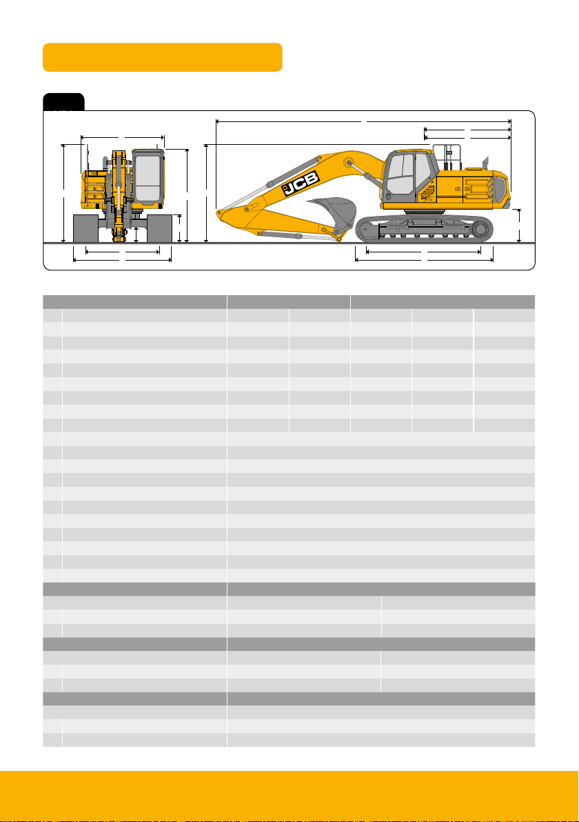
Static Dimensions
Fig 1
Fig 1
Dimensions in mm
Machine Type 210 220
Undercarriage options LC SC LC SLC SC
A Track length on ground 3660 3370 3660 3660 3370
B Undercarriage overall length 4460 4170 4460 4460 4170
C Track gauge 2390 2170 2390 2170 2170
D Width over tracks (500mm trackshoes) 2890 2670 2890 2670 2670
D Width over tracks (600mm trackshoes) 2990 2770 2990 2770 2770
D Width over tracks (700mm trackshoes) 3090 2870 3090 2870 2870
D Width over tracks (800mm trackshoes) 3190 2970 3190 2970 2970
D Width over tracks (900mm trackshoes) 3290 - 3290 - -
E Counterweight clearance 1077
F Tail length 2813
G Tail swing radius 2846
H Width of upper superstructure 2700
H Width of upper superstructure – Xd/Hd 2828
I Height over cab 3030
J Height over FOPS guard/Xd FOPS cage 3102
J Height over grab rail 3170
J Height over grab rail – folded handrail 2744
K Ground clearance 485
L Track height 885
Boom option Mono
Dipper lengths 2.4m 3.0m
M Transport length without bucket 9624 / 9597 9562 / 9540
N Transport height without bucket 3200 / 3090 3086 / 3025
Boom option TAB
Dipper lengths 2.4m 3.0m
M Transport length without bucket 9622 / 9600 9410 / 9424
N Transport height without bucket 3266 / 3225 3152 / 3170
Boom option LR
Dipper lengths 6.4m
M Transport length 12563
N Transport height 3080
210X 220X 5
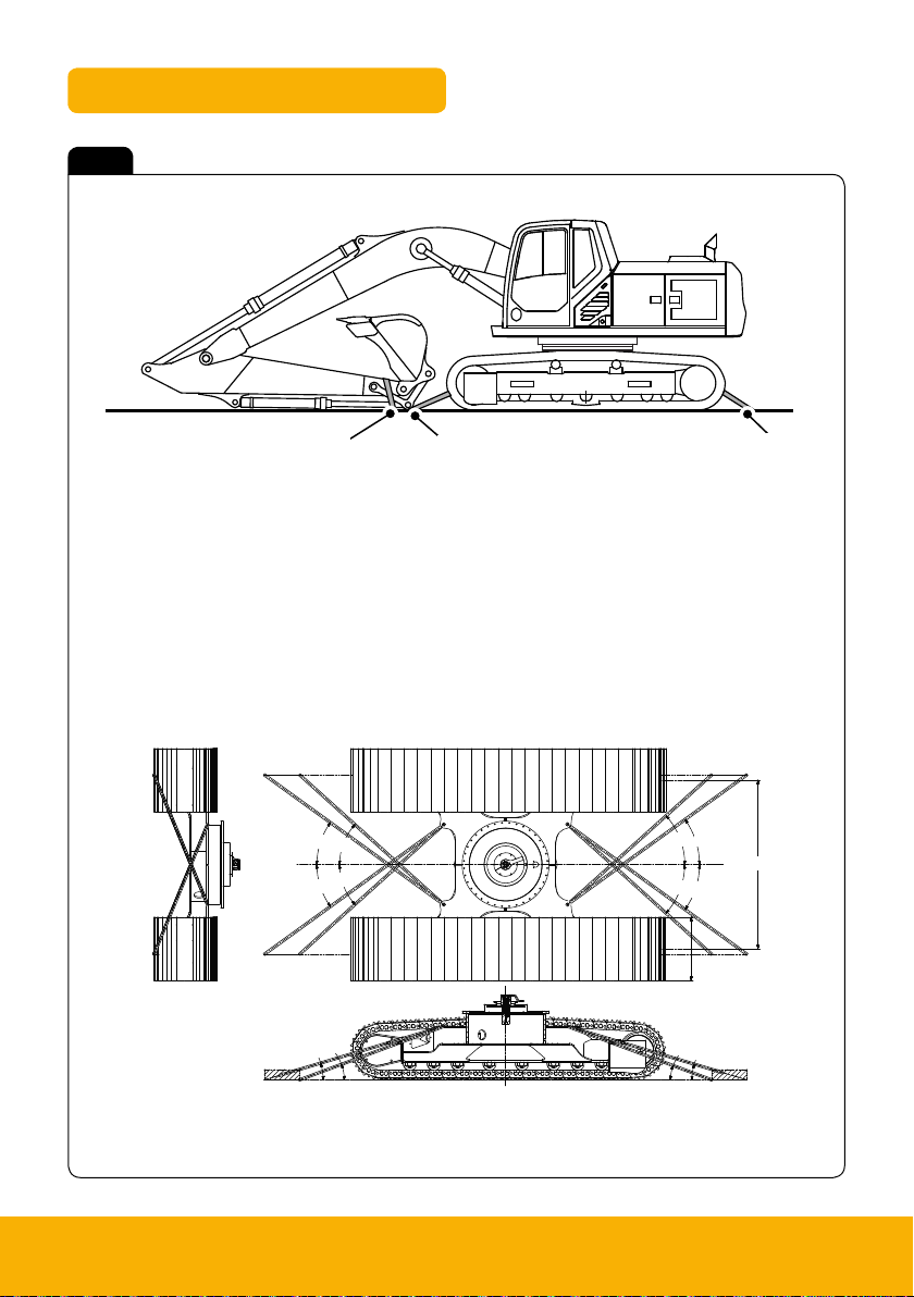
Tie down points
Fig 2
A Undercarriage tie down points
B Dipper tie down points
Standard undercarriage
F
D
F
B
A
E
E
E
C
F
E
F
A
A
C
D
A
B
6 Please see operator manual for full details.
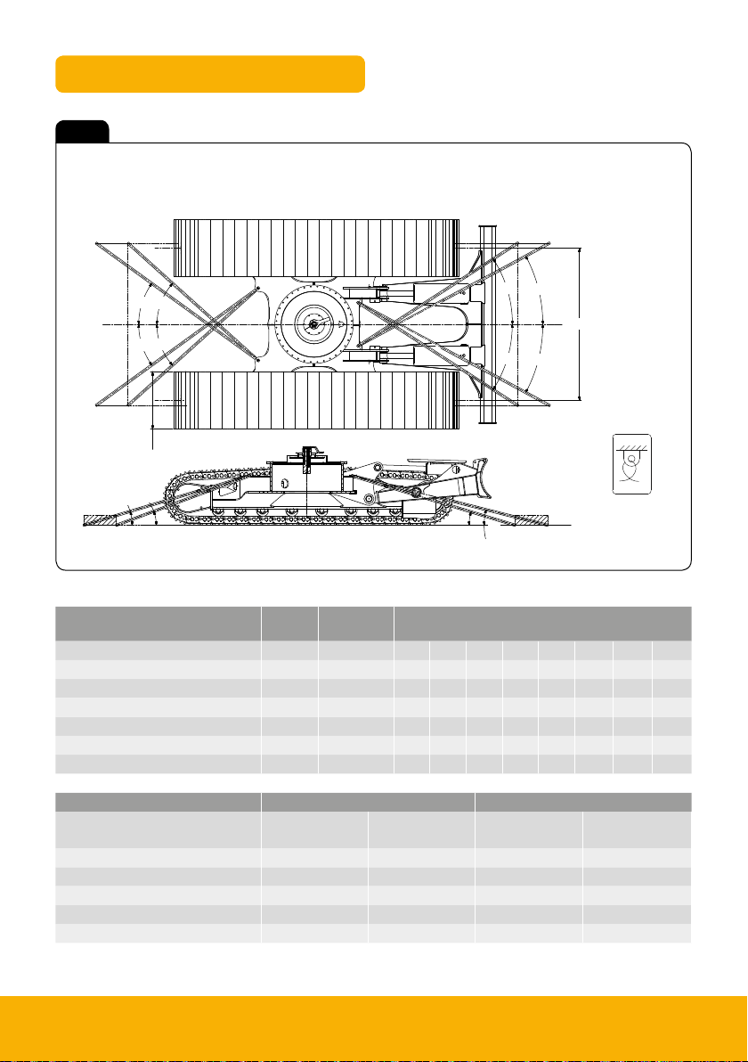
Tie down points
Fig 3
Undercarriage dozer option
F
E
E
F
A
C
D
G
H
B
G
H
J
K
Tie down
position decal
Undercarriage type Track
width
Running gear
CL width
Angles in degree
A B C D E F G H J K
210SC / 220SC / 220SCXD 800mm 2,170mm 20° 16.5° 41° 35°
210LC / 220LC / 220LCXD / 220LCLR 900mm 2,390mm 20° 17° 42° 36°
210NLC / 210NLC / 220NLCXD 700mm 1,990mm 18° 15.5° 39° 34.4°
220SLC / 220SLCLR 800mm 2,170mm 18° 14.5° 38° 31°
220LCD 900mm 2,390mm 20° 17° 42° 36° 33° 28.5° 62.5° 37.4°
220SLCD 800mm 2,170mm 18° 14.5° 38° 34.4° 32° 28° 56° 36°
Undercarriage type Track width Running gear CL width
Front
tie down point
Rear
tie down point
Front
tie down point
Rear
tie down point
210SC / 220SC 104kN 104kN 166kN 166kN
210LC / 220LC 107kN 107kN 172kN 172kN
210SLC / 210SLC 109kN 109kN 174kN 174kN
200LCD 118kN 120kN 189kN 192kN
200SLCD 118kN 113kN 189kN 181kN
210X 220X 7
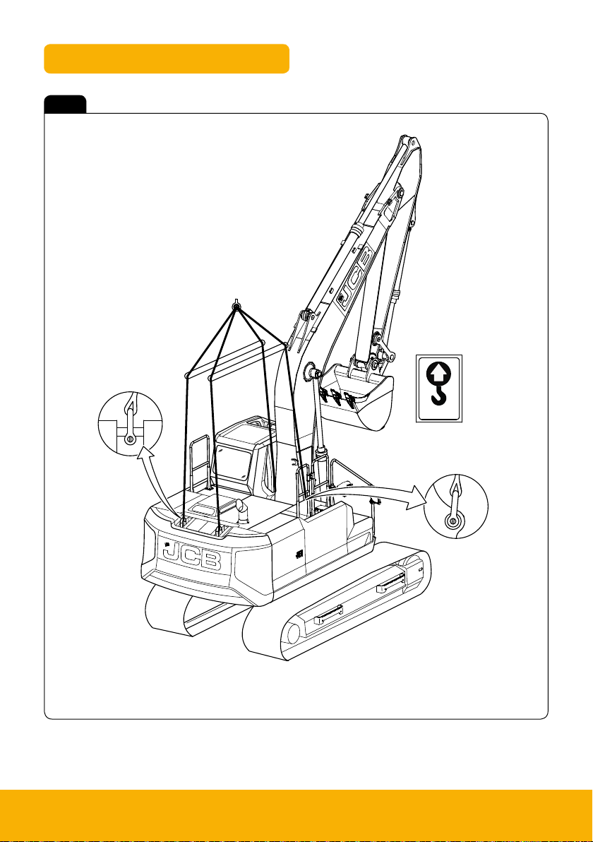
Lifting points
B
A
A
Fig 4
A Lifting points
B Lifting decal
Note: The correct lifting positions are identified on the machine by their decals (B):
8 Please see operator manual for full details.
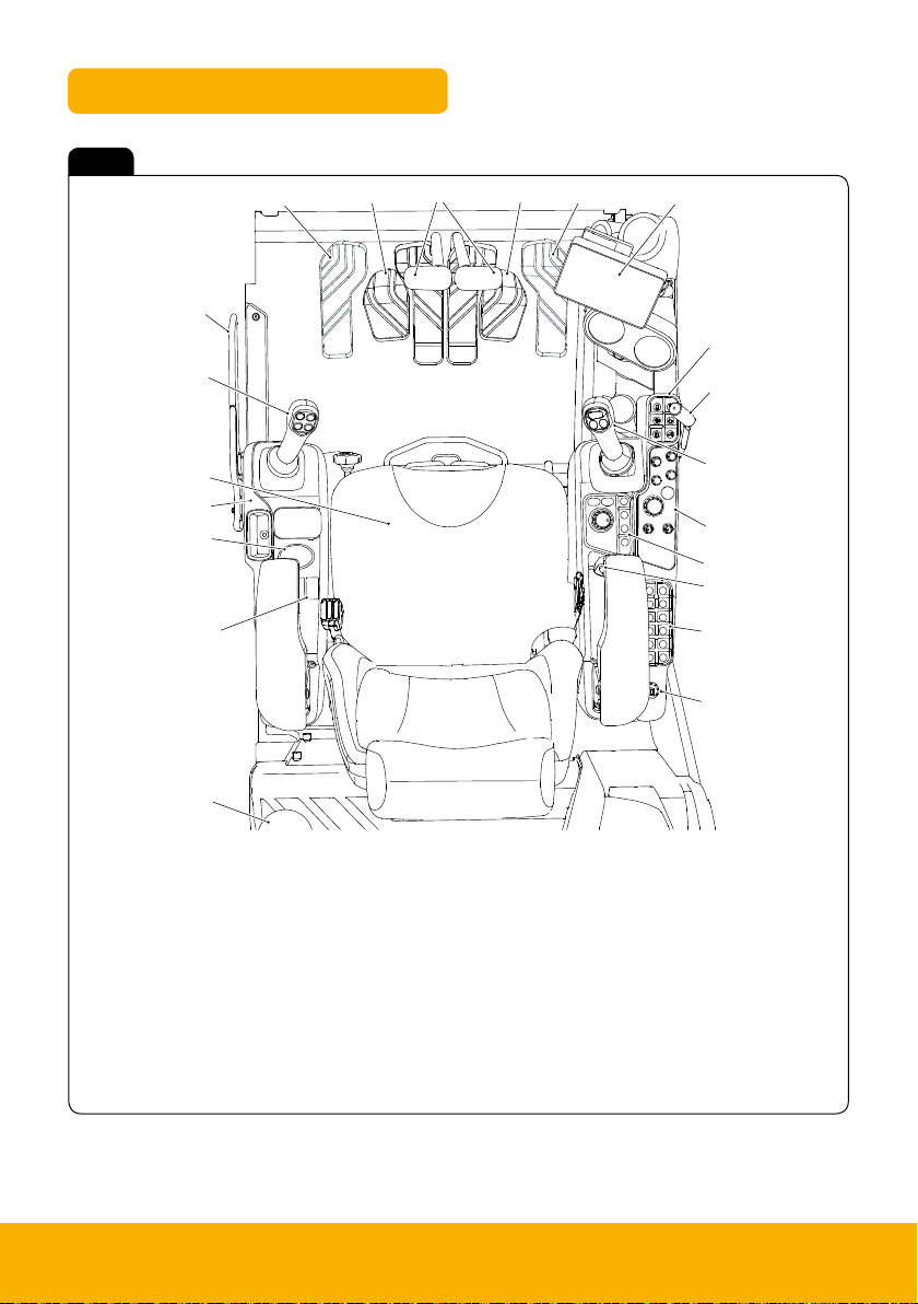
Cab layout & controls
Fig 5
T
S
R
U
A
U
V
B
C
D
Q
P
N
M
L
A Track controls
B Display unit
C Keypad 1
D Dozer control (option)
E Right joystick
F Dial control panel
G Display control panel
H Auxiliary power socket/media socket
J Keypad 2
K Ignition switch
E
F
G
H
J
K
L Fire extinguisher (option)
M Option switches
N Winter control panel (option)
P Left hand pod
Q Operators seat
R Left hand joystick
S
Isolation lever
T TAB (triple articulated boom) foot pedal (option)
U Footrests
V Hammer/Auxiliary foot pedal
210X 220X 9
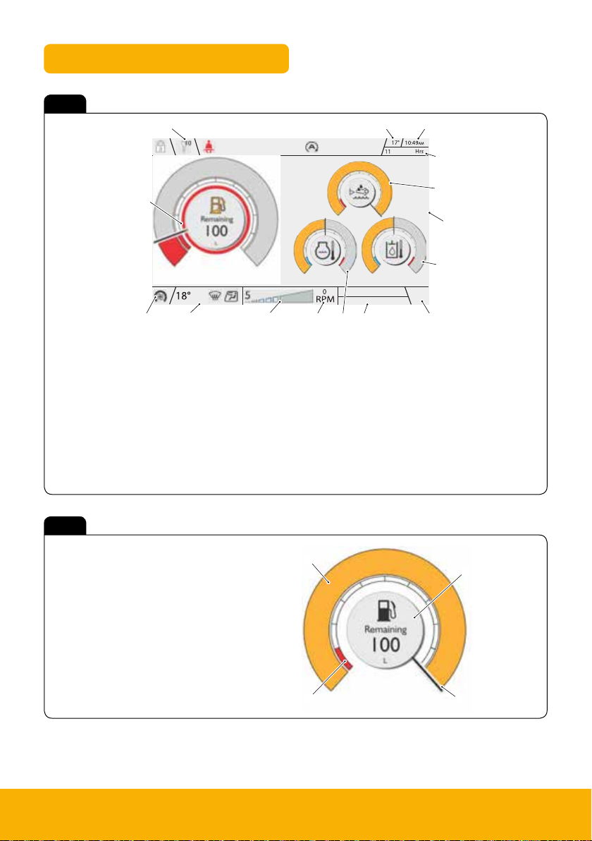
Instrument panel
Fig 6
A
B
C
D
M
K J
L
A Upper ribbon icons
B Ambient temperature
C Clock
D Machine hours
E Camera screen (if camera mode selected)
F Volume or phone/media
G Source/detail information
H Engine RPM (Revolutions Per Minute)
Fig 7
A Warning band
B Main band
C Fuel information
D Needle
P
E
Q
H
G F
N
J Power band
K Lower ribbon HVAC
(Heating Ventilation Air Conditioning) icons
L HVAC/Fan speed
M Fuel level gauge
N Coolant temperature gauge
P DEF fluid level gauge
Q Hydraulic oil temperature gauge
B
C
10 Please see operator manual for full details.
A
D
 Loading...