

Page 1

Quick Start Guide
Tracked Excavators
210X 220X
1
Page 2

Disclaimer
>
This Quick Start Guide is to provide quick and simple information to the Operator and
does not include any health and safety aspects. In addition, because of our continual
development of machines, features described in this Quick Start Guide may differ from
those on your machine. No errors and emissions be entirely ruled out. This Quick Start
Guide DOES NOT replace the Operators Manual. You MUST read ALL the disclaimers
and safety and other instructions in the Operators Manual before initially operating this
product. Accordingly, no legal claims can be entertained on the basis of the data,
illustrations or descriptions in this Quick Start Guide. This machine should not be
operated by any person who isn’t appropriately qualified or had the appropriate training.
Operation of this machine without periodic maintenance could cause it to malfunction.
For more information please contact your JCB Dealer.
2 Please see operator manual for full details.
Page 3

Index
Intended use .......................................................................................................................................4
Static dimensions ................................................................................................................................5
Tie down points .................................................................................................................................6
Lifting points .......................................................................................................................................8
Cab layout & controls .........................................................................................................................9
Start up sequence .............................................................................................................................17
Shutdown sequence .........................................................................................................................18
Hydraulic quick hitch .........................................................................................................................19
Lifting mode .....................................................................................................................................20
Maintenance position ........................................................................................................................21
Service / maintenance schedule ........................................................................................................22
Fluids & lubricants .............................................................................................................................26
Troubleshooting / FAQs ....................................................................................................................27
Your notes ........................................................................................................................................29
210X 220X 3
Page 4

Intended use
General
> Machine Type – Heavy Excavator
> Self propelled machine with a tracked undercarriage
> 360° revolving upper structure with boom, dipper, bucket and slew mechanism
Intended Use
> The machine is intended to be used in normal conditions for the applications and in the
environmental condition as described in the operators manual
> When used normally with a bucket fitted to the machine the work cycle consists of, digging,
elevating, slewing and the discharging of material without movement of the undercarriage.
> Applications include earthmoving, road construction, building and construction, landscaping and
similar applications.
> An excavator can also be used for object handling if it is suitably equipped with the relevant parts
and systems.
> The machine must not be used in the following scenarios because of the risk of overturning; used
for forestry, used with attachments of unknown weight, used on surfaces of unknown stability. This
list is not exhaustive.
> If the machine is to be used in applications where there is a high silica concentration, risk due to
materials containing asbestos or similar hazards, additional protective measures such as the use of
PPE (Personal Protective Equipment) may be required.
> The machine should not be operated by any person who does not have an appropriate level of
qualification ,training or experience of use of this type of machine.
> Prior to use of the machine, its suitability (size, performance, specification etc.) should be considered
with regards to the intended application and any relevant hazards that may exist.
4 Please see operator manual for full details.
Page 5
J
P
M
F
D
C
A
B
L
G
E
H
N
K
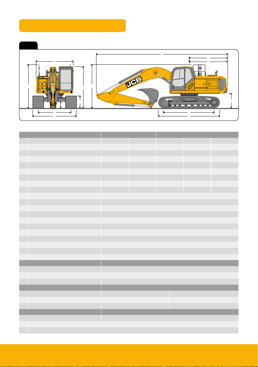
Static Dimensions
Fig 1
Fig 1
Dimensions in mm
Machine Type 210 220
Undercarriage options LC SC LC SLC SC
A Track length on ground 3660 3370 3660 3660 3370
B Undercarriage overall length 4460 4170 4460 4460 4170
C Track gauge 2390 2170 2390 2170 2170
D Width over tracks (500mm trackshoes) 2890 2670 2890 2670 2670
D Width over tracks (600mm trackshoes) 2990 2770 2990 2770 2770
D Width over tracks (700mm trackshoes) 3090 2870 3090 2870 2870
D Width over tracks (800mm trackshoes) 3190 2970 3190 2970 2970
D Width over tracks (900mm trackshoes) 3290 - 3290 - -
E Counterweight clearance 1077
F Tail length 2813
G Tail swing radius 2846
H Width of upper superstructure 2700
H Width of upper superstructure – Xd/Hd 2828
I Height over cab 3030
J Height over FOPS guard/Xd FOPS cage 3102
J Height over grab rail 3170
J Height over grab rail – folded handrail 2744
K Ground clearance 485
L Track height 885
Boom option Mono
Dipper lengths 2.4m 3.0m
M Transport length without bucket 9624 / 9597 9562 / 9540
N Transport height without bucket 3200 / 3090 3086 / 3025
Boom option TAB
Dipper lengths 2.4m 3.0m
M Transport length without bucket 9622 / 9600 9410 / 9424
N Transport height without bucket 3266 / 3225 3152 / 3170
Boom option LR
Dipper lengths 6.4m
M Transport length 12563
N Transport height 3080
210X 220X 5
Page 6
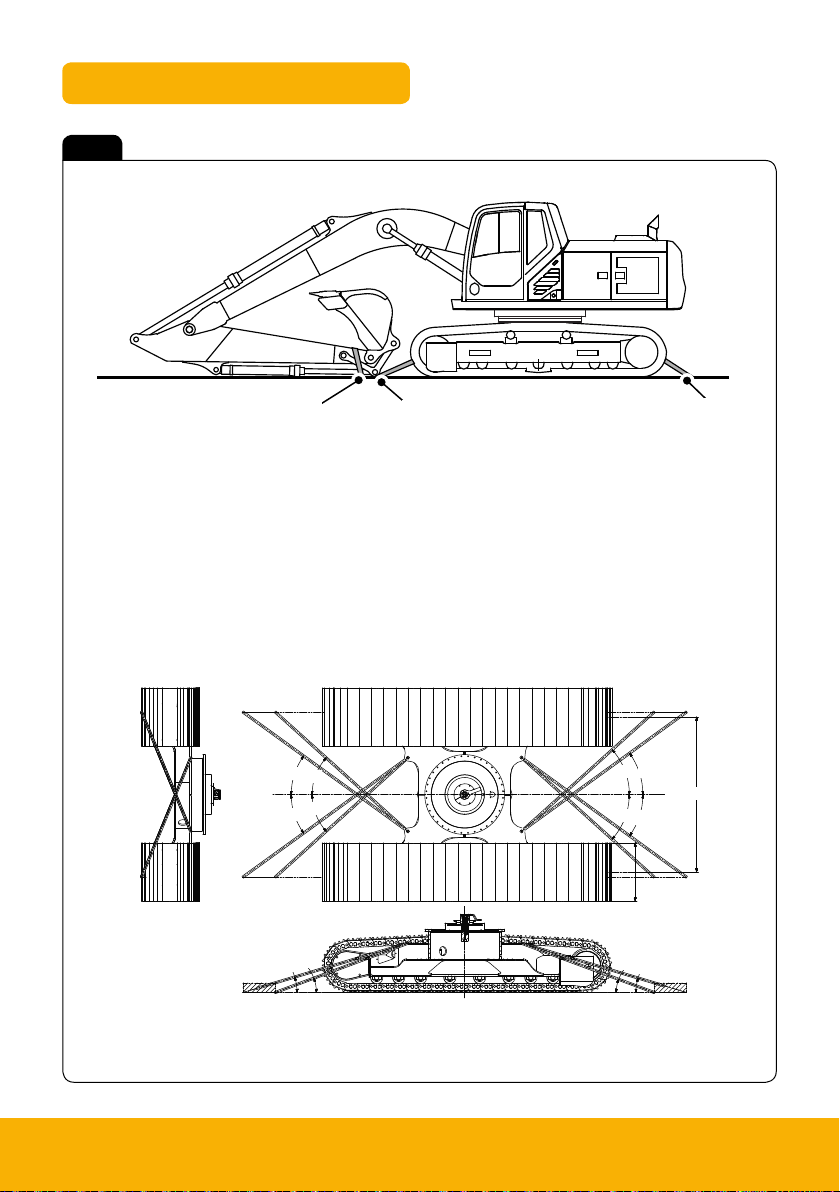
Tie down points
Fig 2
A Undercarriage tie down points
B Dipper tie down points
Standard undercarriage
F
D
F
B
A
E
E
E
C
F
E
F
A
A
C
D
A
B
6 Please see operator manual for full details.
Page 7
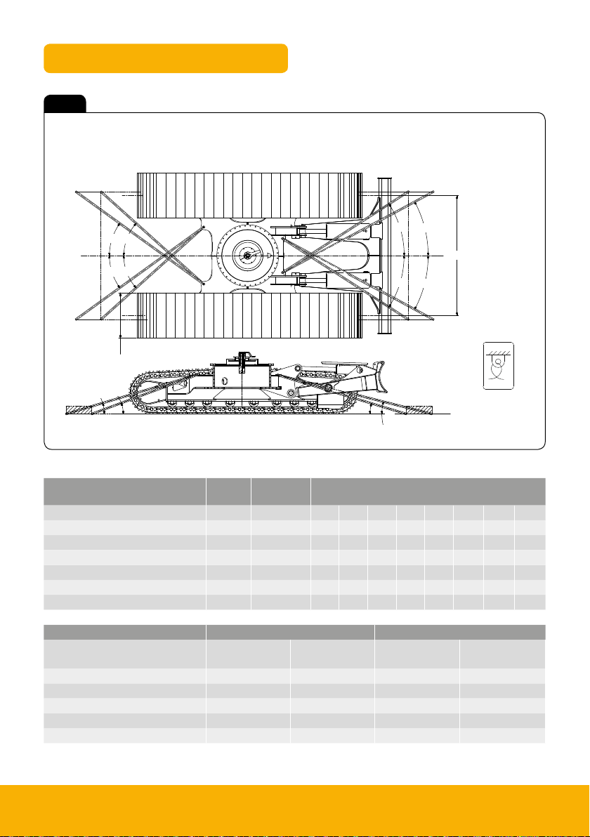
Tie down points
Fig 3
Undercarriage dozer option
F
E
E
F
A
C
D
G
H
B
G
H
J
K
Tie down
position decal
Undercarriage type Track
width
Running gear
CL width
Angles in degree
A B C D E F G H J K
210SC / 220SC / 220SCXD 800mm 2,170mm 20° 16.5° 41° 35°
210LC / 220LC / 220LCXD / 220LCLR 900mm 2,390mm 20° 17° 42° 36°
210NLC / 210NLC / 220NLCXD 700mm 1,990mm 18° 15.5° 39° 34.4°
220SLC / 220SLCLR 800mm 2,170mm 18° 14.5° 38° 31°
220LCD 900mm 2,390mm 20° 17° 42° 36° 33° 28.5° 62.5° 37.4°
220SLCD 800mm 2,170mm 18° 14.5° 38° 34.4° 32° 28° 56° 36°
Undercarriage type Track width Running gear CL width
Front
tie down point
Rear
tie down point
Front
tie down point
Rear
tie down point
210SC / 220SC 104kN 104kN 166kN 166kN
210LC / 220LC 107kN 107kN 172kN 172kN
210SLC / 210SLC 109kN 109kN 174kN 174kN
200LCD 118kN 120kN 189kN 192kN
200SLCD 118kN 113kN 189kN 181kN
210X 220X 7
Page 8
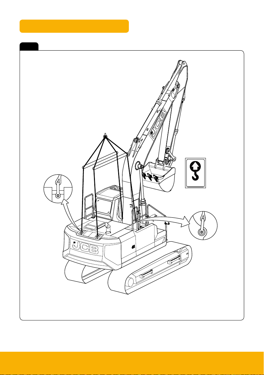
Lifting points
B
A
A
Fig 4
A Lifting points
B Lifting decal
Note: The correct lifting positions are identified on the machine by their decals (B):
8 Please see operator manual for full details.
Page 9
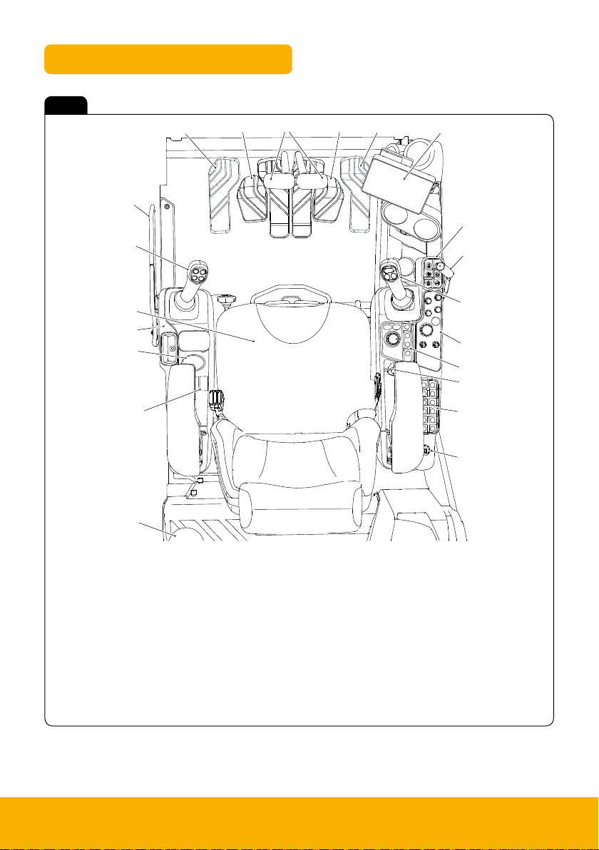
Cab layout & controls
Fig 5
T
S
R
U
A
U
V
B
C
D
Q
P
N
M
L
A Track controls
B Display unit
C Keypad 1
D Dozer control (option)
E Right joystick
F Dial control panel
G Display control panel
H Auxiliary power socket/media socket
J Keypad 2
K Ignition switch
E
F
G
H
J
K
L Fire extinguisher (option)
M Option switches
N Winter control panel (option)
P Left hand pod
Q Operators seat
R Left hand joystick
S
Isolation lever
T TAB (triple articulated boom) foot pedal (option)
U Footrests
V Hammer/Auxiliary foot pedal
210X 220X 9
Page 10
Instrument panel
Fig 6
A
B
C
D
M
K J
L
A Upper ribbon icons
B Ambient temperature
C Clock
D Machine hours
E Camera screen (if camera mode selected)
F Volume or phone/media
G Source/detail information
H Engine RPM (Revolutions Per Minute)
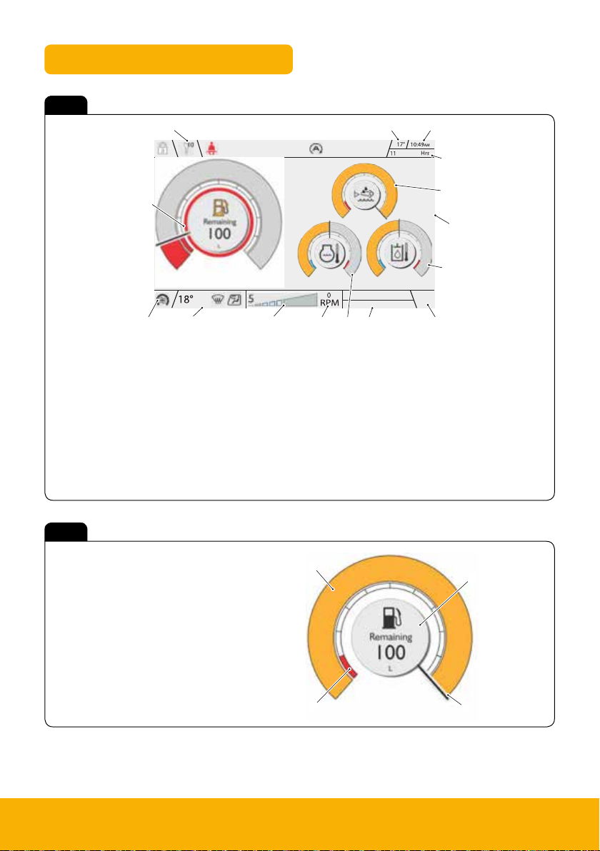
Fig 7
A Warning band
B Main band
C Fuel information
D Needle
P
E
Q
H
G F
N
J Power band
K Lower ribbon HVAC
(Heating Ventilation Air Conditioning) icons
L HVAC/Fan speed
M Fuel level gauge
N Coolant temperature gauge
P DEF fluid level gauge
Q Hydraulic oil temperature gauge
B
C
10 Please see operator manual for full details.
A
D
Page 11

Rotary controller 1
Fig 8
A Rotary media volume control:
Rotate clockwise to increase, anti-clock wise
to decrease. Push to mute.
H
A
B Rotary media track/source control:
Rotate clockwise to skip forward, anti-clockwise
to skip backwards. Push to select source.
C Engine start/stop button.
D Rotary wiper control:
Wiper of f, intermediate 1, intermediate
2, continuous. Push to wash screen.
E Rotary worklight control:
Worklights off, worklights front, worklights rear,
Worklights custom. Push to configure custom.
F Rotary machine operating
powerband control:
Push to select heavy power band.
G Rotary HVAC (Heating Ventilation Air
Conditioning)/heater temperature control:
Rotate clockwise to increase temperature,
anticlockwise to decrease temperature.
Push to select demister.
H HVAC/heater fan speed control:
Rotate clockwise to increase fan speed, anti-clockwise
to decrease fan speed. Push to selec t vent mode.
G
B
C
F
E
D
210X 220X 11
Page 12

Rotary controller 2
Fig 9
A Quick hitch confirm button
B Lift mode on/off but ton
C Overload warning on/off button
D Quickhitch lock /unlock button
E Rotary control
F Back button
G Home button
Keypad 1
F
G
E
A
B
C
D
Fig 10
A Slew lock on/off button
B Beacon on/off button
C Camera button
D Controls isolate button.
E Travel speed button
F Engine auto idle button
12 Please see operator manual for full details.
F
E
D
A
B
C
Page 13

Keypad 2
Fig 11
A Call accept/reject/end button
Immobiliser key number 2
B Boom float button
Immobiliser key number 4
C Exhaust filter button, Immobiliser key number 6.
Press the but ton to initiate or defer SCR (Selective
Catalytic Reduction)
D Aux 1 button. Immobiliser key number 8
M
L
K
A
B
C
E Aux 2 button. Immobiliser key number 0
F Not used
G Immobiliser back but ton
H Aux 2 button. Immobiliser key number 9
J Auxiliary venting, Immobiliser key number 7
K Slew smoothing button
Immobiliser key number 5
L Reverse fan button, Immobiliser key number 3.
When pressed the fan timer is overridden and the fan
is reversed immediately for the time pre-set by the
operator using the control box.
M Tool select but ton, Immobiliser key number 1
J
AUX
H
G
D
E
F
210X 220X 13
Page 14

Pedals and controls
3
1
2
4
D
C
B
A
LH Joystick (ISO control pattern)
Fig 12
A Boom slew priority
B Horn
C Hot key
D Propor tional Auxiliary Control high flow (option)
1 Left: Slew to the left
2 Right: Slew to the right
3 Forward: Move the dipper outwards
4 Backward: Move the dipper inwards
3
14 Please see operator manual for full details.
2
4
1
Page 15

Pedals and controls
2
4
3
1
A
B
C
D
RH Joystick (ISO control pattern)
Fig 13
A Proportional auxiliary control low flow (option)
B 2 - speed tracking
C One touch engine idle
D Power boost
1 Backward: Raise the boom
2 Forward (lower the boom)
3 Left: Fill the bucket
4 Right: Empty the bucket
1
2
3
4
210X 220X 15
Page 16

Pedals and controls
2
1
A
B
1
2
Track levers
Fig 14
A Left track lever
B Right track lever
C Right track pedal
D Left travel pedal
E Footrests
TAB boom controls (option)
Fig 15
A Pedal
B Ram
1 Heel end of pedal: Extend the ram
2 To end of the pedal: Retract the ram
A
D
B
C
A
16 Please see operator manual for full details.
Page 17

Start up sequence
AUX
A
B
C
E
F
H
G
J
K
L
M
D
1
Insert Isolator Key
Insert isolator key (A) and turn
in a clockwise direction.
A
4
Engine Pre Heat
Turn ignition to position 1 (A).
A
2
Check Isolation Lever
Ensure the hydraulic isolation
lever is in the lower position (B).
A
5
Disarm Immobiliser
If fitted disarm by entering PIN
code using the 12 way keypad.
3
Engage Seat Belt
Engage seat belt (A) into latch
(B) before starting machine.
A
B
6
Start Machine
Hold down the Star t/Stop
button until the machine starts.
7
Raise LH Isolater lever
Raise the left hand isolator lever
(A) to activate the hydraulics.
8
Press 2 GO Button
If enabled press 2 GO button (A)
to activate hydraulics. Hydraulic
isolation icon (B) will disappear
9
Operate Machine
All controls are now active
and the machine is now ready
to use.
from the dash when active.
A
A
B
210X 220X 17
Page 18

Shutdown and auxiliary venting
Shutdown sequence
1 2 3
Park machine up
Leave and secure
Isolate machine
Park machine on solid level
ground with the attachment and
dozer (if fitted) on the ground.
Switch off all switches. Leave
machine using the handrails
and footholds. Close and lock
all doors and windows to
secure machine.
Auxiliary venting (within one minute of shutdown)
1
Turn ignition on
Turn ignition to position 1 (A)
so that the instrument panel
and switches become active.
A
2
Raise isolator lever
While sitting in the operating
station with engine off raise the
isolator lever.
A
Turn isolator key anti-clockwise
and remove key.
A
3
Press 2 GO button
(if activated)
Press 2 GO but ton to activate
hydraulics. Instrument panel
will illuminate when active.
4
Operate aux switches
Continuously operate the
auxiliar y but tons/sliders
5
Rotate joysticks
Continuously rotate both joysticks
for 5 seconds.
(depending on machine
configuration) A + B (page
14/15) on both joysticks for
5 seconds.
18 Please see operator manual for full details.
6
Auxiliaries vented
The auxiliaries should now be
vented and pressure relieved.
If it feels as though there is still
pressure in the system, repeat
from step 4.
Page 19

B
Hydraulic quick hitch
B
Standard attachments
1
Start unlock process
To start quick hitch unlock
process ensure hydraulics
are live then press quick hitch
sequence button (A).
A
4
Remove attachment
To disengage the
quickhitch jaws,
crowd the
attachment for
3 seconds.
The attachment
can now be
removed.
2
Confirm process
Switch (B) will flash and the
buzzer will sound constantly for
5 seconds indicating confirmation
is required. Press quickhitch
confirm button (B). If not pressed
within 5 seconds the process will
need to be
restarted.
5
Change attachment
Operate the machine to engage
the jaw (D) with the attachment (E)
and then full crowd the attachment
to align latch.
E
B
A
D
3
Indicator
When the sequence is
confirmed the confirmation
button will flash and a bucket
crowd symbol will show on the
display (B).
B
6
Lock quickhitch
To engage the lock on the
quickhitch press the following
button (B) and visually check
hitch is locked.
B
Specialised attachments
4a 4b
Crowd override
For large attachments where
bucket crowding is not possible
follow steps 1 to 3, and then hold
rotary dial (C) for 10 seconds.
C
Remove attachment
An audible buzzer will sound
after 10 seconds to indicate that
the jaws of the quickhitch are
open. The attachment can now
be removed.
Specialised attachments are any
attachment that when crowded
fully could foul the boom/dipper.
210X 220X 19
Page 20

Lifting mode
1 2 3
Mode selection
Power band adjustment
Overload alarm
Activate button (A) on
controller 2.
4 5
Autoidle de-activate
Autoidle de-activates when in
lift mode, symbol B will not be
on the screen.
In lift mode the power band
adjusts from A to B.
Disable lift mode
To disable lift mode press
button (A) on rotary
controller 2.
Overload warning alarm
is automatically activated,
highlighted on screen by (A).
A
Lift overload warning system
1 The machine will remember
the last setting after ignition
on/ off.
2 When working with
overload system enabled the
display symbol (A) will illuminate
red. This is because the machine
has reached maximum lift
capacity or the boom ram is
fully retracted
A
20 Please see operator manual for full details.
Page 21

Maintenance position
Fig 16
A
A Excavator End
1. Park the machine on solid, level ground, with the upper structure parallel to the undercarriage.
2. If necessary, lower the dozer blade.
3. Lower the excavator end to ground.
4. Stop the engine.
5. Remove the ignition key.
6. Release the hydraulic pressure and the tank pressure.
7. Isolate the battery to prevent the accidental operation of the engine.
210X 220X 21
Page 22

Service/Maintenance Schedule
Daily Checks (10h) Check
Check condition of attachments / optional equipment
Grease attachments / optional equipment as required
Clean bodywork and framework
Check condition of bodywork and framework
Check condition of cab/canopy including seat belt
Check engine for leaks and oil level
Check condition of drive belt
Check fuel system for leaks and contamination
Drain water from water separator on fuel filter
Check engine coolant for leaks, contamination and level
Check condition of cooling pack and system
Check hydraulic oil level
Check window washer fluid level
Check the condition of the fire ex tinguisher
Check operation of all services i.e. excavator, dozer etc.
Check operation of all electrical equipment i.e horn, alarms etc.
Check operation of the hour meter
Check the track and running gear operation
Visual check
Lubricate
Clean
Visual check
Visual check
Visual check
Visual check
Visual check
Clean
Visual check
Visual check
Visual check
Visual check
Visual check
Operate
Operate
Visual check
Operate
Weekly Checks (50h) Check
Grease slew ring bearing Lubricate
Clean cooling pack Clean
Check condition and tension of tracks Visual check
Check hydraulic hoses / pipework for leaks and damage Visual check
Check condition of the rams Visual check
Check the condition of the electrical wiring Visual check
Clean the battery terminals Clean
Check the operation of the battery isolator Operate
Please refer to the operators handbook for a complete service and maintenance guide.
22 Please see operator manual for full details.
Page 23

Service & Maintenance Points
Fig 17
A Air filter
B Fuse box
C Batteries
D Battery isolator
E Window washer fluid bottle
F Radiator(s)
A
F
B
D
Fig 18
A Main fuel filter
B Engine oil filter
C Lubricity filter (option)
D Fuel sedimenter
E Hydraulic oil level indicator
F Fuel tap
G Water separator
H Fuel tank drain tap
Fig 19
A Fresh air cab filter
C
A
C
B
E
F
E
D
G
H
A
210X 220X 23
Page 24

C
B
Service & Maintenance Points
Fig 20
A DEF (Diesel Exhaust Fluid)
filler cap
B Diesel fuel filler cap
C Hydraulic oil filler cap
D Engine oil dip stick
E Engine oil filler cap
F Coolant expansion tank
G Slew gearbox filler
H Slew gearbox dipstick
J Blower booster filter (option)
K Slew gear grease bath
Fig 21
A Cover
B Handle
C Lock
A
G
K
A
H
F
J
D
E
24 Please see operator manual for full details.
C
B
C
Page 25

B
Service & Maintenance Points
Upper step – DEF filler access
Fig 22
A Latch
B Cover
C DEF tank filler cap
C
Lower step – Toolbox/refuel pump access (if fitted)
Fig 23
A
A Fuel hose
B Close-off valve
C Switch
C
B
A
210X 220X 25
Page 26

Fluids and Lubricants
Item Capacity Fluid/Lubricant JCB
Part Number
Fuel Tank 387L Diesel 400 - Refer to ‘Fuel’
DEF (Diesel Exhaust
Fluid) Tank
Engine (Oil)
Cooling System 38L JCB Antifreeze HP/Coolant 4 00 6 /112 0 20L ASTM D3306,
Track Gearbox (each) 3.5L JCB HD90 Gear Oil 4000/0301 5L
Slew Gearbox 8L JCB HD90 Gear Oil 4000/0305 20L
Track Rollers and Idler
Wheels
Recoil Spring Cylinder JCB Special HP Grease 40 03/ 2017 0.4k g
Hydraulic System 250L JCB Hydraulic Fluid HP32,
Slew Ring Bearings 0.1k g JCB Special H P Grease 4 0 03/2017 0.4kg
(2)
47. 7 L DEF 4009/0120 20L Refer to ‘DEF’
20.4 L -30°C (-22°F) to 30°C (86.0°F)
JCB Engine oil UP 5W/30
-30°C (-22°F) to 46°C (114.7°F)
JCB Engine oil UP 5W/40
-15°C (5°F) to 46°C (115°F)
JCB Engine oil UP 10W/30
JCB HD90 Gear Oil 4000/0305 20L
-20°C (-4°F ) to 15°C (59°F)
JCB Hydraulic Fluid HP46,
-10°C (14°F) to 30°C (86°F)
JCB Hydraulic Fluid HP68,
0°C (32°F) to 40°C (104°F)
40 01/3105 20L API CJ-4
4001/3405 20L
4001/3005 20L
4002/1024 200L
4002/0803 200L
4002/0701 200L
Container
Size
Specification
ASTM D4985,
ASTM D6510,
SEA (Society
of Automotive
Engineers)
J1034, BS6580
(1992), AFNOR
NF R15- 60
Slew Ring Gear Teeth 17k g JCB Special HP Grease 4003/2006 12. 5kg
All other grease As required JCB Special HP Grease 4003/2006 12.5k g
JCB part numbers are liable to change and may also vary by region. For the latest information, always
check with your dealer/distributor.
26 Please see operator manual for full details.
Page 27

Troubleshooting/FAQs
Issue / FAQ Resolution / Answer
Ensure that the start-up sequence has been followed (Page 17).
My machine will not start
I can’t activate the Hydraulics
How do I know if the hydraulic
2Go system is enabled/disabled?
If the machine is fitted with an immobiliser make sure the
correct pin has been entered.
If the machine still will not start contact dealer.
Make sure that the isolation lever is in the upper position
(page 17).
If the 2Go system is fitted, ensure that the isolation lever is in
the upper position and the 2Go button has been pressed.
There is an issue with the machine and an error code is present
on the display, this would inhibit the hydraulics.
If none of the above contact dealer.
If the system is disabled,
the following symbol will
appear on the dash upon
start up.
Contact dealer for more
information on activating/
deactivating 2Go system.
210X 220X 27
Page 28

Troubleshooting/FAQs
Issue / FAQ Resolution / Answer
Can I open the quickhitch with
the attachment on the ground?
Why is there an audible buzzer
in the cab when I am lifting a
large load?
Can I disable the lift overload
warning system when not object
handling?
250 hour greasing – does it
matter if greased every day?
250 hour greasing – After the
first 250 hours does the bush
then need greasing daily?
250 hour greasing – After 250
hours does the bush need to
be replaced?
250 hour greasing – without daily
greasing what cleans all the dirt
out of the bush?
How do I switch between
ISO/SAE joystick patterns?
The quickhitch can be opened with the attachment on the
ground using the quickhitch override feature (Page 19).
The lift overload warning system has detected a load that is near the
limits of the machine, reduce the load to prevent over turn (Page 20).
To disable the lift overload warning system when not object
handling press the lift overload but ton on rotary dial 2 (page 20).
No this has no adverse effect on the graphite impregnated bushes.
No simply grease at each 250 hour interval .
No simply grease and continue work.
The machine is fitted with a one way seal stopping dirt entering
the bush, but allows old grease out when greasing.
The ISO/SAE changeover switch is located within the fusebox
clearly labelled (if option fitted).
• Switch the head unit source to Bluetooth.
How do I pair my phone
to Bluetooth?
• Turn on Bluetooth on your mobile phone.
• Search for the head unit and pair your phone.
• Pairing code is 1234.
Can you deactivate the
travel alarm?
Yes you can disable the travel alarm through the dash.
The cool box works in conjunction with the HVAC system. If set
My cool box is blowing hot air.
to hot the cool box will warm, however the internal vent can be
shut to prevent hot air from entering.
28 Please see operator manual for full details.
Page 29

Your Notes
210X 220X 29
Page 30

Your Notes
30 Please see operator manual for full details.
Page 31

Your Notes
210X 220X 31
Page 32

JCB Sales Limited, Rocester, Staffordshire, Uni ted Kingdom ST14 5JP
Tel: +44 1889 590312 Email: salesinfo@jcb.com
Download the very latest information on this product range at: w ww.jcb.com
All right s reserved. No p art of this pub lication may be rep roduced, stored i n a retrieval sys tem, or transmi tted in any form or by any other means, el ectronic, mech anical, photoco pying
or other wise, without p rior permissi on from JCB Sales . All references in t his publicati on to operating wei ghts, sizes, capa cities and other performance m easurements a re provided
for guida nce only and may var y dependant upo n the exact spec ification of the machine. They shou ld not therefore b e relied upon in rel ation to suitab ility for a par ticular applic ation.
Guidance and advice shoul d always be sought f rom your JCB Deale r’. JCB reserves the r ight to change spec ifications wit hout notice. Ill ustrations an d specificatio ns shown may
include op tional equipm ent and accessori es.
9818/ 3300
 Loading...