

Page 1

Quick Start Guide
Compact Excavators
18z-1, 19c-1, 19c-1 EP
1
Page 2

Disclaimer Index
Intended Use ......................................................................................................................................4
>
This Quick Reference Guide is to provide quick and simple information to the Operator
and does not include any health and safety aspects. In addition, because of our continual
development of machines, features described in this Quick Reference Guide may differ
from those on your machine. No errors and emissions be entirely ruled out.
Dimensions ........................................................................................................................................5
Tie Down Points ............................................................................................................................ 6-7
Lifting Points .......................................................................................................................................8
>
This Quick Reference Guide DOES NOT replace the Operators Manual. You MUST
read ALL the disclaimers and safety and other instructions in the Operators Manual
before initially operating this product. Accordingly, no legal claims can be entertained on
the basis of the data, illustrations or descriptions in this Quick Reference Guide.
>
This machine should not be operated by any person who isn’t appropriately qualified or
had the appropriate training.
>
Operation of this machine without periodic maintenance could cause it to malfunction.
For more information please contact your JCB Dealer.
Cab Layout & Controls ................................................................................................................. 9-14
Start Up Sequence ...........................................................................................................................15
Hydraulic Hitch Unlock .....................................................................................................................16
Mechanical Hitch Unlock ..................................................................................................................17
Shutdown & Auxiliary Venting ...........................................................................................................18
Maintenance Position ........................................................................................................................19
Service / Maintenance .......................................................................................................................20
Access Covers ............................................................................................................................ 21-2 2
Fluids & Lubricants ............................................................................................................................23
Machine Attachments .......................................................................................................................24
Troubleshooting / FAQs ..............................................................................................................25 -26
Your Notes .......................................................................................................................................27
23Please see operator manual for full details.
18z-1, 19c-1, 19c-1 EP
Page 3
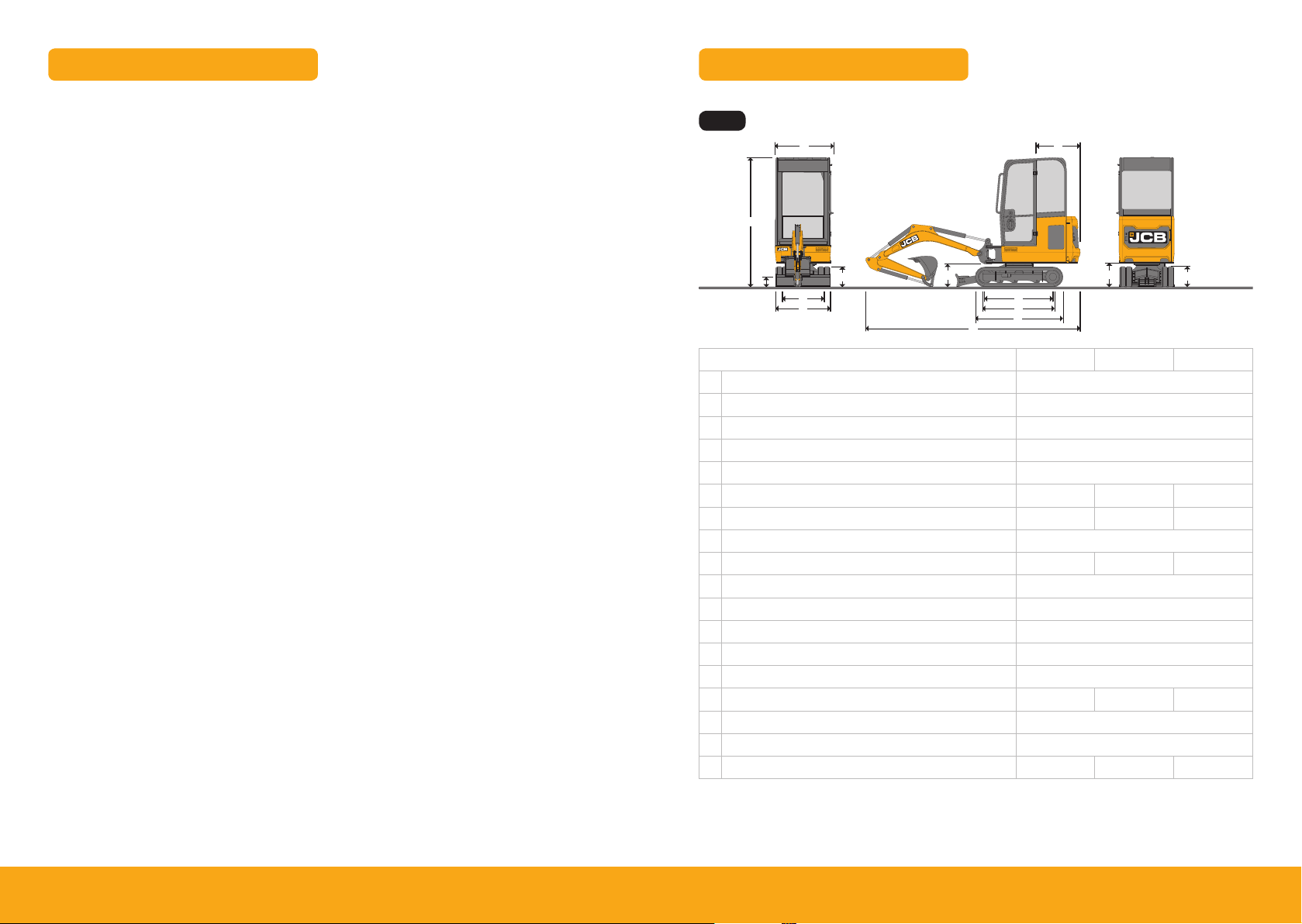
Intended Use
Dimensions
General
> Machine Type – Compact Excavator
> Self propelled machine with a tracked undercarriage
> 360° revolving upper structure with boom, dipper, bucket and slew mechanism
Intended Use
> Machine intended to be used in normal conditions as detailed in the operators manual
> With bucket fitted, machine work cycle consists of digging, elevating, slewing and discharging
of materials
> Applications include earthmoving, road construction, building and construction, landscaping etc.
> Can be used for object handling if fitted with relevant parts and systems
> Not intended for use in mining and quarrying applications, demolition, forestry, any use
underground and any explosive atmospheres
> Must not be used for forestry, used with attachments of unknown weight, used on sur faces with
unknown stability – list not exhaustive
>
PPE may be required in cer tain applications/environments e.g. high silica concentration or asbestos
> The machine should not be operated by any person without appropriate qualifications, training
or experience of using this type of machine
> Prior to use, the machines suitability should be considered with regards to the intended
applications and any hazards which may be present
Fig 1
F
G
H
L
I
J
D
K
E
N
A
B
C
M
Machine model 18z-1 19c-1 19c-1 EP
A Sprocket idler centres mm 1218
B Track length on ground mm 1220
C Undercarriage overall length – rubber mm 1578
Undercarriage overall length – steel mm 1578
D Kingpost clearance mm 409
E Tailswing radius mm 685 110 3 110 3
F Overall width of superstructure mm 996 996 996
G Height over cab mm 2324
Height over canopy mm 2340 2324 2 324
H Ground clearance mm 162
I Track gauge – Retracted mm 750
Track gauge – Extended mm 1110
J Width over tracks – Retracted mm 980
Width over tracks – Extended mm 133 0
K Transport length with standard dipper mm 3547 3860 3862
L Track height mm 367
M Counterweight clearance mm 434
N Operating mass* kg 1749 1910* * 1943* *
45Please see operator manual for full details.
* Standard machine specification, please see data plate for speci fic machine weight.
* * Cab variant.
18z-1, 19c-1, 19c-1 EP
Page 4
Operation
Transporting the Machine
Figure 90. Method 3
E
E
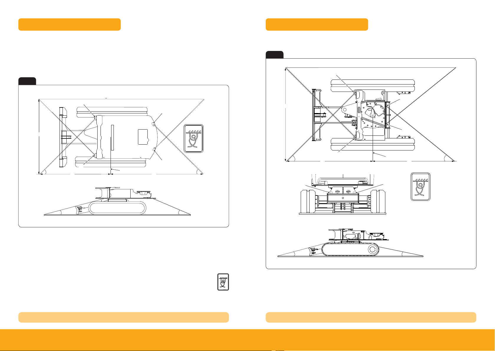
Tie Down Points
Operation
Transporting the Machine
Figure 89. Method 2
When transporting the machine one of the following three methods should be used:
Method 1
Fig 2
Tie Down Points
Method 2
Fig 3
A
A
H
C D
A
F
E
A Front slew spine tie-down point
C Angle = 35° to 46°
E Angle = 9° to 15°
G Length = 2,720mm to 1,943mm
I Slew ring centre line
I
B Rear slew spine tie-down point
D Angle = 45° to 50°
F Leng th = 2,499mm to 1,846mm
H Length = 2,500mm
J Tie down decal
B
G
J
B
E
Tie Down Posi tion Decal
H
C
B
F
A Front slew spine tie-down point
C Angle = 35° to 46°
E Angle = 9° to 15°
G Length = 2,282mm to 1,670mm
I Slew ring centre line
A
I
B
B Rear slew spine tie-down point
D Angle = 35° to 45°
F Length = 2,499mm to 1,846mm
H Length = 2 ,500mm
J Tie down decal
B
B
G
J
D
REFER TO OPER ATORS MANUAL TRANSPORTING MACHINE REFER TO OPER ATORS MANUAL TRANSPORTING MACHINE
67Please see operator manual for full details.
18z-1, 19c-1, 19c-1 EP
Page 5
About the Product
Console Switches
Console Switches
Figure 18.
About the Product
Console Switches
About the Product
Console Switches
switch
No LED illumination
Two or three position rocker switch. The switch functions operate when the ignition
switch is in the on position.
Position : 1 = Off
Position : 2 = Boom and front cab work light on
Position : 3 = All work lights on
About the Product
Console Switches
switch
No LED illumination
Two or three position rocker switch. The switch functions operate when the ignition
switch is in the on position.
Position : 1 = Off
Position : 2 = Boom and front cab work light on
Position : 3 = All work lights on
Two or three position rocker switch. The switch functions operate when the ignition
switch is in the on and off positions.
Position : 1 = Off
Position : 2 = Beacon on
Controls isolation switch. Two position momentary rocker switch. Press switch to
activate/de-activate the control.
Position : 1 = Rest position.
Position : 2 = Momentary position (activate/de-activate hydraulic controls).
About the Product
Console Switches
switch
No LED illumination
Two or three position rocker switch. The switch functions operate when the ignition
switch is in the on position.
Position : 1 = Off
Position : 2 = Boom and front cab work light on
Position : 3 = All work lights on
Two or three position rocker switch. The switch functions operate when the ignition
switch is in the on and off positions.
Position : 1 = Off
Position : 2 = Beacon on
Controls isolation switch. Two position momentary rocker switch. Press switch to
activate/de-activate the control.
Position : 1 = Rest position.
Position : 2 = Momentary position (activate/de-activate hydraulic controls).
Three position rocker switch. The switch functions operate when the ignition switch is
in the on position. The wiper will self-park when switched off.
Position : 1 = Off
Position : 2 = On
Position : 3 = Washer on (if installed)
Two position rocker switch. The switch functions operate when the ignition switch is in
the on position and auxiliary has been selected.
Position 1: Bi-directional mode- Double acting attachment
Position 2: Hammer mode- Single acting attachment
About the Product
Console Switches
switch
No LED illumination
Two or three position rocker switch. The switch functions operate when the ignition
switch is in the on position.
Position : 1 = Off
Position : 2 = Boom and front cab work light on
Position : 3 = All work lights on
Two or three position rocker switch. The switch functions operate when the ignition
switch is in the on and off positions.
Position : 1 = Off
Position : 2 = Beacon on
About the Product
Console Switches
switch
No LED illumination
Two or three position rocker switch. The switch functions operate when the ignition
switch is in the on position.
Position : 1 = Off
Position : 2 = Boom and front cab work light on
Position : 3 = All work lights on
Two or three position rocker switch. The switch functions operate when the ignition
switch is in the on and off positions.
Position : 1 = Off
Position : 2 = Beacon on
Controls isolation switch. Two position momentary rocker switch. Press switch to
activate/de-activate the control.
Position : 1 = Rest position.
Position : 2 = Momentary position (activate/de-activate hydraulic controls).
Three position rocker switch. The switch functions operate when the ignition switch is
in the on position. The wiper will self-park when switched off.
Position : 1 = Off
Position : 2 = On
Position : 3 = Washer on (if installed)
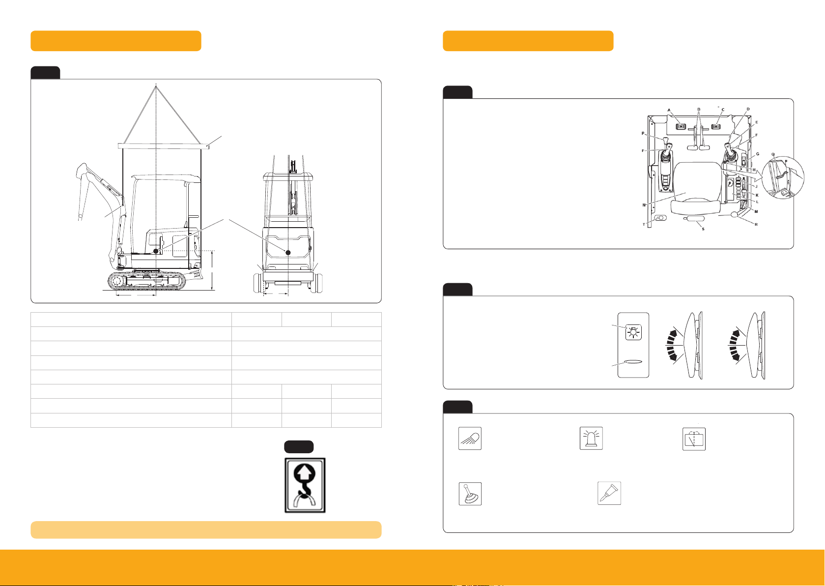
Lifting Points
Operation
Lifting the Machine
7. Check that the lifting eye is positioned directly above the machine centre of gravity.
Figure 84.
E
Cab & Switch Panel
Fig 4
A
Description 18z-1 19c-1 19c-1 EP
A Boom Lif t Point
B Dozer Blade Lift Point
C Spreader Bar
D Centre of Gravity
E mm 632 792 792
F mm 659 639 639
G mm 525 533 533
F
*COG = Centre of Gravity
The correct lifting positions are identified on the machine by their labels:
REFER TO OPER ATORS MANUAL TRANSPORTING MACHINE
C
D
Operator Station Layout – 18z-1, 19c-1
Fig 6
A Auxiliary pedal
B Track Controls
C Swing left/ right
D Heater Controls
E Horn
F Excavator arm controls
G Dozer control lever
H Ignition switch
J Right console switches
L Instrument panel
M Radio (if installed)
N Operator seat
P Control isolation lever
Q Undercarriage track
extension lever
R Fire extinguisher (18z-1)
S Fire extinguisher (19c-1)
T Window washer bottle
K Hand throttle
B
B
Switch Panel – 18z-1, 19c-1
G
Fig 5
Lifting point
Fig 7
A Graphic symbol
B Light bar
C 3 way position switch
D 2 way position switch / momentary switch
Fig 8
Work Lights
1 Off
2 On (Boom)
3 On (Boom & Cab)
A
B
Beacon
1 Off
2 On (Boom)
C D
1
2
3
1
2
3
Window Wipers
1 Off
2 Intermit tent/
continuos/washer
Position label.
Controls Isolation (2GO)
1 Off
2 Activate/de-activate
hydraulic controls
Bi-Directional and Hammer Mode Selector
1 Bi-directional mode – Double acting
2 Hammer mode – Single acting
89Please see operator manual for full details.
18z-1, 19c-1, 19c-1 EP
Page 6
Operation
Instruments
Instruments
Figure 50.
Figure 50.
B
A
Figure 50.
B
A
Operation
Instruments
Figure 51.
A
B C
D
E
F
G
Operation
Instruments
Figure 51.
A B
C
D
E
F
G
Operation
Instruments
Figure 51.
E
F
G
Operation
Instruments
F
G
Operation
Instruments
Figure 51.
E
F
G
Operation
Instruments
Figure 51.
E
F
G
Operation
Instruments
E
F
G
Operation
Instruments
E
F
G
Operation
Instruments
E
F
G
Operation
Instruments
Operation
Instruments
Figure 52.
A
B
Cab & Switch Panel
About the Product
Console Switches
Figure 19.
G
H
Instrument Panel
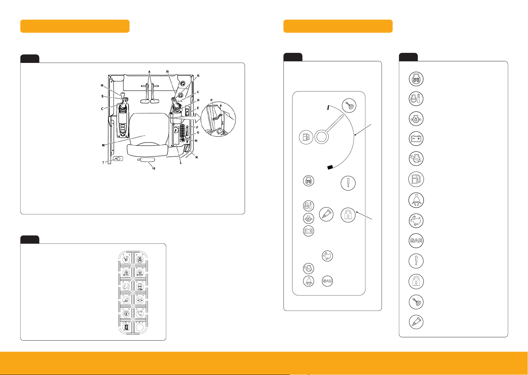
Operator Station Layout – 19c-1 EP
Fig 9
A Track controls
B Heater controls
C Excavator arm controls
D Ignition Switch
E Dozer control lever
F Switch panel
G Hand throttle
H Auxillary power socket
K Radio (if installed)
L Instrument panel
M Operator seat
N Control Isolation lever
P Undercarriage track extension lever
Q Fire extinguisher
R Swing lef t/right
S Auxiliary control
T Window washer bottle
Switch Panel – 19c-1 EP
Fig 10
Instrument Panel – 18z-1, 19c-1
Fig 11 Fig 12
A Fuel level guage
B Warning and indicator lamps
A
B
Engine pre-heat
Coolant temperature
Engine oil pressure
Battery charging
Service due warning
Low fuel indicator
Seat belt
High speed travel
SAE active
A Control Isolation Switch (2Go)
B Aux 1 selection switch
C Lift overload switch on/off switch
D Worklights on/off switch
E Wiper/ washer on
F Auto-hydraulic warming switch
G H+ mode selec tion switch
H Aux 2 selec tion switch
I Auto idle on/off switch
J Beacon on/off switch
K Q-hitch sequence switch
1011Please see operator manual for full details.
0 1
A
2 3
B
4 5
C
D
E
F
7
6
8 9
I
J
K
Key
Black Text = Standard equipment
Blue Text = Not Used
Master warning
Immobilisers active
Hydraulics active
Aux 1 – single acting
18z-1, 19c-1, 19c-1 EP
Page 7
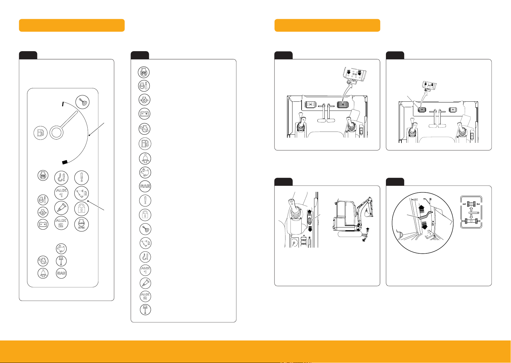
Operation
Operating Levers/Pedals
Figure 62. 16C-1 and 18Z-1
A B
B
A
Operation
Operating Levers/Pedals
Figure 65.
B
C
B
B
C C
A
Figure 66. 16C-1 and 18Z-1
Operation
Operating Levers/Pedals
Figure 64.
Operation
Operation
Operating Levers/Pedals
Figure 65.
B
C
B
B
C C
A
Instrument Panel
Operation
Instruments
Figure 52.
Operation
Instruments
Instruments
Figure 50.
B
A
Operation
Instruments
Figure 50.
B
A
Operation
Instruments
Figure 52.
A
Operation
Instruments
Figure 52.
A
B
Operation
Instruments
Figure 52.
A
B
Operation
Instruments
Figure 52.
A
B
Operation
Instruments
Figure 51.
A B
C
D
E
F
G
Operation
Instruments
Figure 51.
A B
C
D
E
F
G
Operation
Instruments
Figure 51.
E
F
G
Operation
Instruments
F
G
Operation
Instruments
Figure 51.
E
F
G
Operation
Instruments
Figure 51.
E
F
G
Operation
Instruments
E
F
G
Operation
Instruments
E
F
G
Operation
Instruments
E
F
G
Operation
Instruments
Operation
Instruments
A
Operation
Instruments
Figure 52.
A
Foot Controls & Dozer Lever
Instrument Panel – 19c-1 EP
Fig 13 Fig 14
A Fuel level guage
B Warning and indicator lamps
1213Please see operator manual for full details.
A
B
Engine pre-heat
Coolant temperature
Engine oil pressure
Battery charging
Service due warning
Low fuel indicator
Seat belt
High speed travel
SAE active
Master warning
Immobilisers active
Hydraulics active
Quick hitch unlock
Lift overload warning
Aux 1 – double acting
Aux 1 – single acting
Aux 2 – low flow
Swing active
Swing Controls – 18z-1, 19c-1 Auxiliary Controls – 18z-1, 19c-1
Fig 15 Fig 16
A Swing left
A Auxiliary pedal
B Swing right
A
Dozer Lever Retracting Undercarriage Lever
Fig 17 Fig 18
A
B
A Lower the dozer
B Raise the dozer
C Control lever
C
B
A
A Track Extension Lever
B Upward - Retract
C Downward - Extend
B
C C
18z-1, 19c-1, 19c-1 EP
B
Page 8
Maintenance
Service Points
Service Points
Figure 112.
B
C
D
A
H
Operation
Entering and Leaving the Operator Station
Figure 20.
Operation
Seat Belt
Seat Belt
Figure 34.
About the Product
Interior Switches
Figure 16.
Operation
Working with the Excavator Arm
Figure 71.
Figure 72.
Operation
Starting the Engine
Figure 40.
About the Product
Interior Switches
Figure 16.
Joystick & Dozer Lever
Operation
Operating Levers/Pedals
Figure 62. 16C-1 and 18Z-1
A
B
B
A
Figure 63. 19C-1
A
B
B
A
Operation
Operating Levers/Pedals
Figure 67. 19C-1
Operation
Operating Levers/Pedals
Figure 64.
Operation
Operation
Operating Levers/Pedals
Figure 65.
B
C
B
B
C C
A
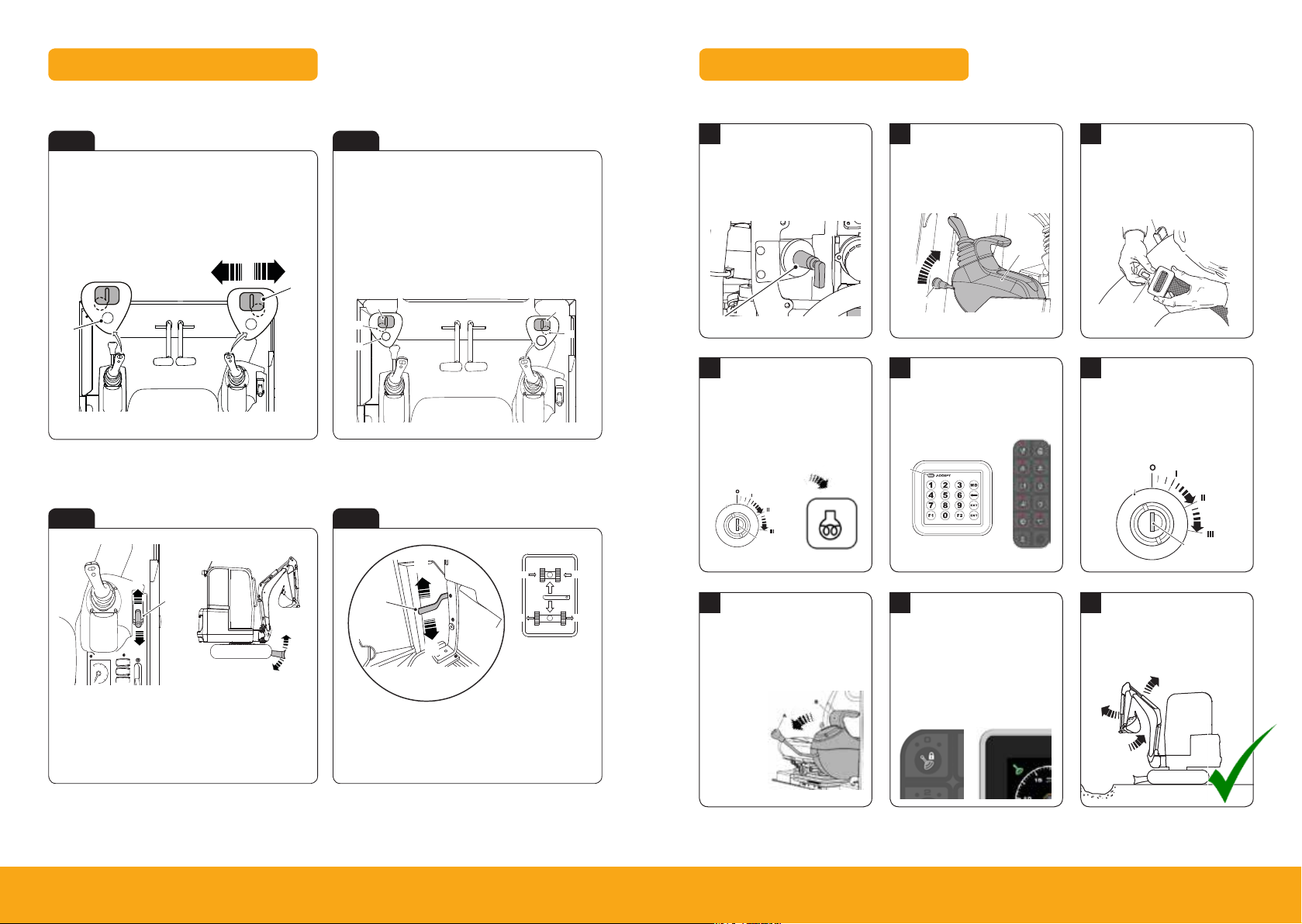
Swing Controls – 19c-1 EP Auxiliary Controls – 19c-1 EP
Start Up Sequence
Fig 19 Fig 20
A Swing left
B Swing right
C Swing thumb wheel control
D Change over button
D
A
C
B
A Lower the dozer
B Raise the dozer
C Control lever
Dozer Lever Retracting Undercarriage Lever
Fig 21 Fig 22
1415Please see operator manual for full details.
B
A
C
A Tilt/grab changeover for tilt-rotator
B Boom swing/Aux change over button
C Thumb wheel control – Aux 2 (Low flow)
D Continuous flow button – Hammer circuit
E Thumb wheel control – Aux 1 (High flow)
Note: A & D located underside of joystick
C
A
B
E
D
B
C C
A Track Extension Lever
B Upward - Retract
C Downward - Extend
1
Insert Isolator Key
Insert isolator key (A) and
turn in a clockwise direction.
A
4
Engine Pre Heat
Turn ignition to position 1 (A)
to pre-heat engine before star t.
Wait until pre-heat symbol (B)
2
Raise LH Arm Rest
Ensure the hydraulic isolation
lever (left hand arm rest) is in
the raised position.
B
A
A Handle B LH arm rest
5
Disarm Immobiliser
If fitted disarm by entering PIN
code using one of the below
methods.
3
Engage Seat Belt
Engage seat belt (A) into latch
(B) before starting machine.
B
A
6
Start Machine
From ignition position 1 turn
ignition to position 3 (A) to star t
the machine.
on instrument panel goes off.
A
B
7
A
B
Lower LH Arm Rest
Lower the LH arm rest to
activate the hydraulics.
Note: If 2 GO enabled go to step 8,
if not go to step 9
A Handle
B LH arm rest
B
8
Press 2 GO Button
If enabled press 2 GO button
(A) to activate hydraulics.
Instrument panel will illuminate
(B) when active.
A B
A
A
B
9
Operate Machine
All controls are now active
and the machine is now ready
to use.
18z-1, 19c-1, 19c-1 EP
Page 9
Attachments
Quickhitch
Figure 104.
Attachments
Quickhitch
Figure 103.
B
Attachments
Quickhitch
Figure 105.
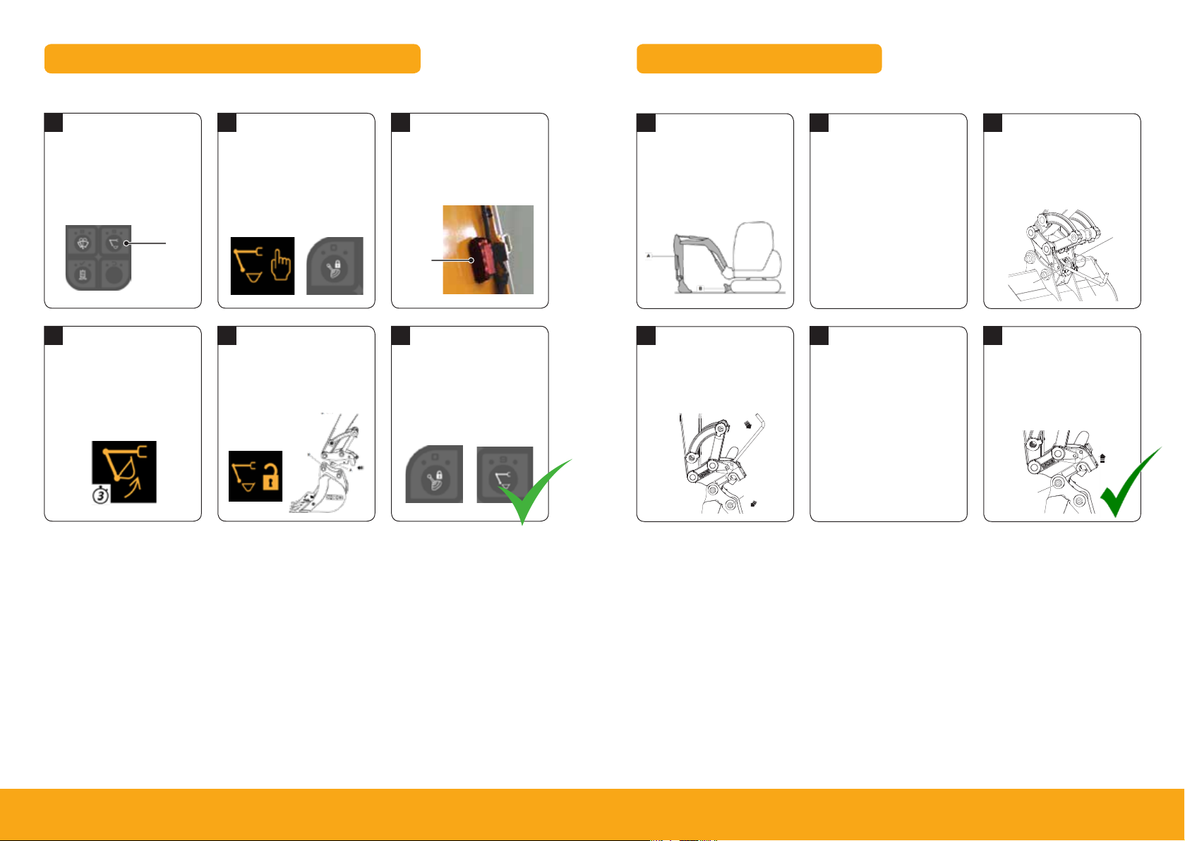
Hydraulic Hitch Unlock Sequence (19c-1 EP only)
Mechanical Hitch Unlock System
Standard Attachments
1
Start Unlock Process
To start quick hitch unlock
process ensure hydraulics are
live then press quick hitch
sequence button (A).
4
Remove Attachment
To disengage the pivot pin,
crowd attachment for 3 seconds
then remove attachment.
Standard Attachments
2
Confirm Process
Instrument panel will indicate
need to confirm process (A).
To confirm process press 2 GO
button (B).
A
B
A
5
Change Attachment
Operate the machine to
engage
the jaw (A) with the
attachment
(B) and then full
crowd the attachment
to align latch.
3
Boom LED Indicator
When the sequence is
confirmed the LED on the
boom will flash red (A).
A
6
Lock Quick Hitch
To engage the lock on the quick
hitch press one of the following
two but tons and visually check
hitch is locked.
A
B
1
Park Machine Up
Park the machine on firm level
ground. Position the attach-
ment (A) just above the ground
and dozer (B) on the ground.
4
Release Attachment
Apply downward pressure to
the tommy bar to release the
buckets rear pivot.
A
2
Disconnect Attachment
Stop the engine, remove any
connected hydraulic hoses and
remove the locking pin.
5
Restart Machine
Start the engine, rest
attachment on the ground
and engage the hydraulics.
3
Insert tommy bar
Insert the tommy bar into the
hole of the latch hook.
A Latch Hook B Tommy Bar
C Hole
A
C
6
Remove Attachment
Slowly roll the quickhitch in the
direction of the arrow whilst
raising the dipper to release the
front pivot (A).
B
A
A
1617Please see operator manual for full details.
18z-1, 19c-1, 19c-1 EP
Page 10
Maintenance
Maintenance Positions
Maintenance Positions
Figure 111.
Shutdown and Auxiliary Venting
About the Product
Console Switches
Figure 19.
G
H
0 1
Operation
Operating Levers/Pedals
Figure 67. 19C-1
E
D
C
Operation
Instruments
Figure 52.
A
Operation
Instruments
Figure 52.
A
B
Operation
Operating Levers/Pedals
Figure 67. 19C-1
E
D
C
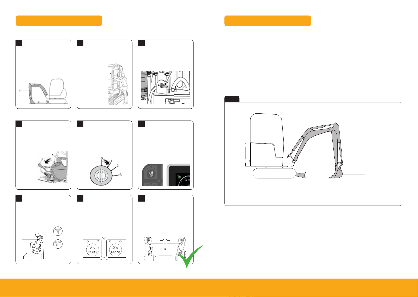
Maintenance Position
Shutdown Sequence
1
Park Machine Up
Park machine on solid level
ground with the attachment (A)
and dozer (B) on the ground.
2
Leave & Secure
Switch off all switches. Leave
machine using the handrails
and footholds.
Close & lock
all doors and
windows to
secure machine.
Auxiliary Venting (Within 1 Minute of Shutdown)*
1
Lower LH Arm Rest
While sitting in the operating
station with engine off lower
LH arm rest.
A Handle
B LH arm rest
4
Select Aux Circuit
Enable aux function on top of
the left control lever (A). Ensure
symbol (B) or (C) is displayed.
B
A
*19c-1 EP only please refer to the operators manual for 19c-1 and 18z-1
1819Please see operator manual for full details.
C
2
Turn Ignition On
Turn ignition to position 1 (A) so
that the instrument panel and
switches become active.
5
Switching Circuits
Change Aux mode between
Aux1 (A) and Aux 2 (B) using
mode select switch on the right
hand console.
A
A
2 3
B
3
Isolate Machine
Turn isolator key anti-clockwise
and remove key.
3
Press 2 GO Button
A
Press 2 GO but ton (A) to
activate hydraulics. Instrument
panel will illuminate (B)
when active.
A B
6
Venting Aux Circuit
Operate the roller switch fully
in both directions to release
stored pressure. Right hand
(A) for Aux 1 and left hand (B)
for Aux.
A
1. Park the machine on solid, level ground
I. Release the two track levers
II. Set the hand throttle lever to the idle position
2. Lower the dozer blade (A)
3. Lower the excavator so the attachment is flat on the ground
Fig 23
B
A
A Attachment flat on the ground
B Dozer blade lowered to ground
4. Stop the engine
5. Discharge the hydraulic pressure (see aux venting operation)
B
6. Isolate the controls and remove ignition key
7. Isolate the battery to prevent accidental operation of the engine
18z-1, 19c-1, 19c-1 EP
Page 11
Maintenance
Service Points
Service Points
General
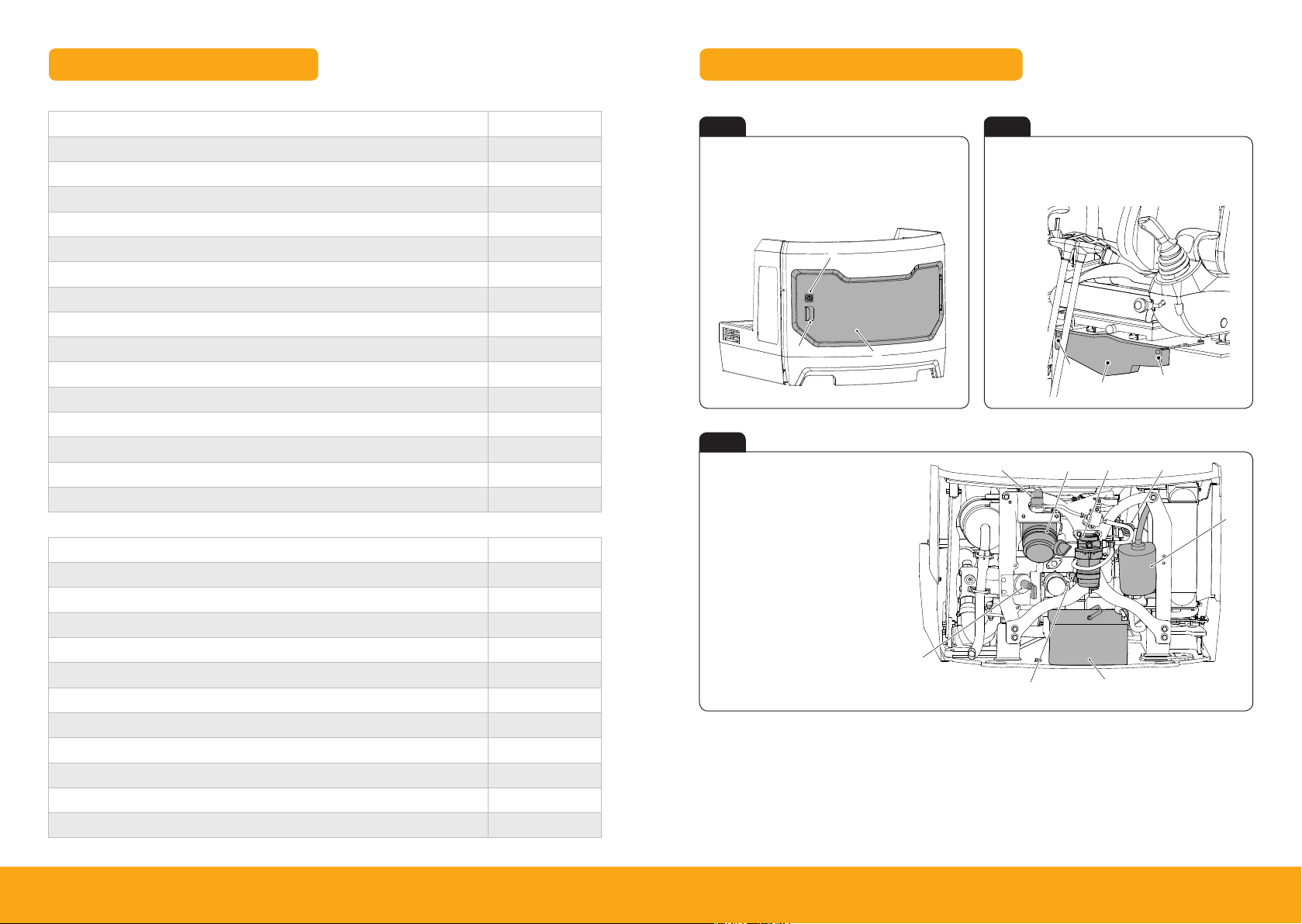
The following illustrations identify the service points for the operator to perform the daily and weekly
maintenance tasks.
Engine Compartment
Figure 112.
F
B
C
A
H
Maintenance
Access Apertures
Access Apertures
Figure 114.
Maintenance
Electrical System
Figure 133.
Service/Maintenance
Access Covers – Service Items and Relays
Daily Checks (10h) Check
Check engine for leaks and oil level Visual check
Check engine coolant for leaks, contamination and level Visual check
Check condition of cooling pack and system Visual check
Check hydraulic oil level Visual check
Check the condition of welded structure Visual check
Check window washer fluid level Visual check
Check condition of bodywork and framework Visual check
Check condition of attachments / optional equipment Visual check
Grease attachments / optional equipment as required Lubricate
Check for excessive exhaust smoke Visual check
Check fuel system for leaks & contamination Visual check
Check operation of all services i.e. excavator, dozer etc. Operate
Check operation of all electrical equipment i.e horn, alarms etc. Operate
Check the track and running gear operation Operate
Check operation of the hour meter Viual check
Weekly Checks (50h) Check
Clean cooling pack Clean
Drain water from water separator on fuel filter Clean
Check condition of drive belt Visual check
Check hydraulic hoses / pipework for leaks and damage Visual check
Check condition of the rams Visual check
Check the condition of the electrical wiring Visual check
Clean the battery terminals Clean
Check condition and tension of tracks Visual check
Check presence of all pivot pin retaining bolts Visual check
Grease slew ring bearing Lubricate
Grease window and door hinges Lubricate
Fig 24 Fig 25
A Lock
B Engine compartment cover
A Fixings
B Relay access cover
C Handle
A
C
Fig 26
B
A Air filter
B Water separator
C Oil filler cap
D Coolant expansion bottle
E Battery
F Engine oil dipstick
G Battery isolator
H Fuel pre filter
G
A
B
E
A
D
2021Please see operator manual for full details.
18z-1, 19c-1, 19c-1 EP
Page 12
Access Covers – Fluid Levels and Fill
Maintenance
Access Apertures
Figure 115.
A B
Maintenance
Service Points
Figure 113.
Fluids and Lubricants
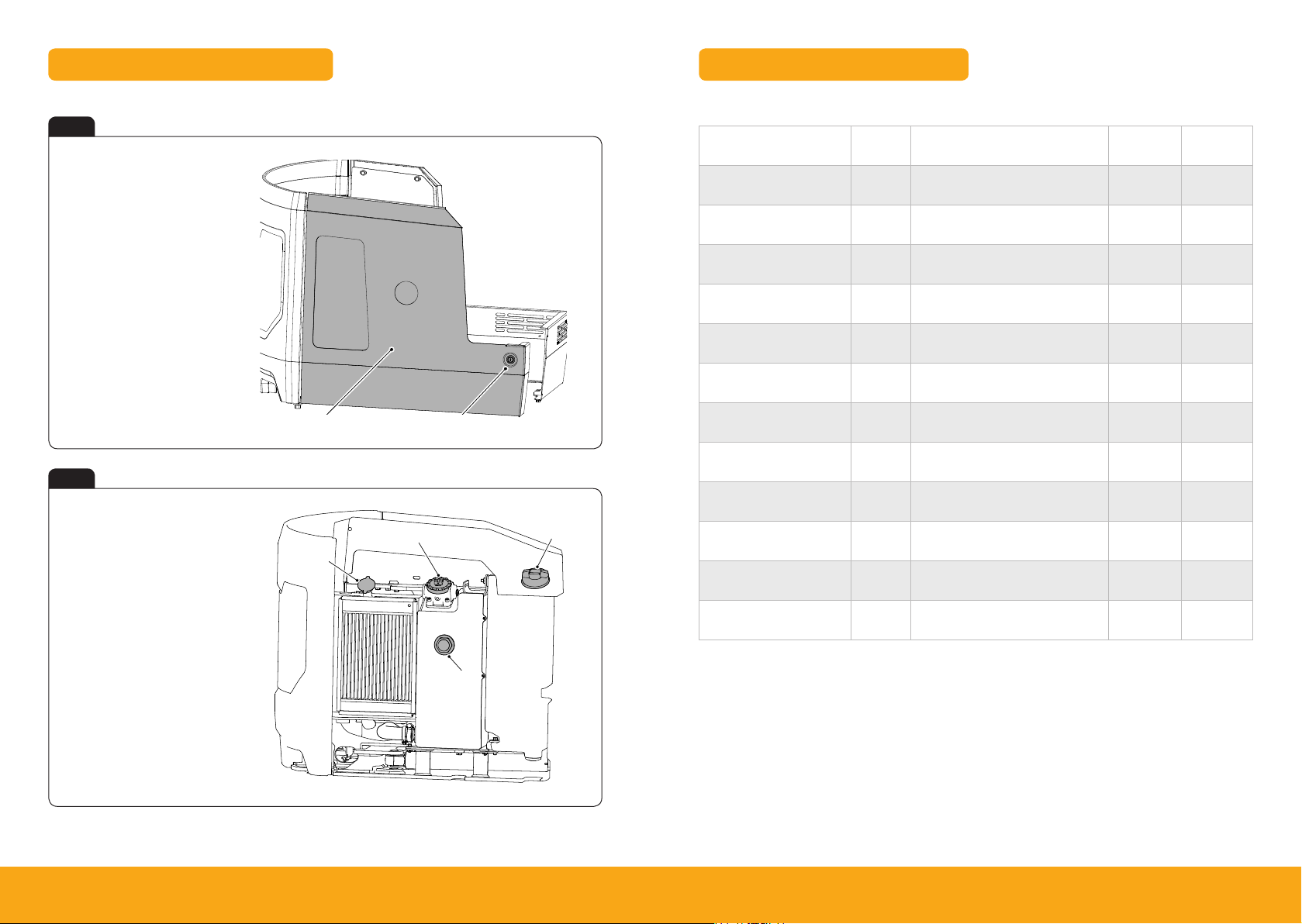
Fig 27
A Hydraulic compartment cover
B Lock
Fig 28
A Radiator cap
B Hydraulic tank filler cap
C Fuel filler cap
D Hydraulic oil level indicator
A
B
Item Capacity Fluid/lubricant
JCB Part
Number
Container
Size
Fuel Tank 20.5L Diesel oil – –
Engine Oil
(Stage 3A Perkins 403D-07)
2.5L
-30°C (-22°F) to 40°C (104°F):
JCB Extreme performance 5W40
4001/ 2 70 5 20L
Engine Coolant (Cab) 4.7L JCB Antifreeze HP / Coolant / Water 4 00 6 /112 0 20L
Engine Coolant (Canopy) 4.2L JCB Antifreeze HP / Coolant / Water 4 0 06 / 1120 20L
Track Gearbox (each) 0.3L
JCB Engine Oil HP SAE 30
(Not Multigrade)
4001/ 0305 20L
Track Idler Wheels 0.3L JCB HP90 Gear Oil 4000/0305 20L
Track Rollers (bot tom) 0.025L JCB HP90 Gear Oil 4000/0305 20L
Hydraulic System 28L
Hydraulic Tank 15 L
C
Slew Ring Bearing
Slew Ring Gear Teeth
All Other Grease
JCB par t numbers are liable to change and may also vary by region.
D
For the latest information, always check with your dealer/distributor.
As
required
As
required
As
required
-20°C (-4°F) to 46°C (114.7°F):
JCB Hydraulic Fluid OP46
-20°C (-4°F) to 46°C (114.7°F):
JCB Hydraulic Fluid OP46
4002/2005 20L
4002/2005 20L
JCB HP Grease 40 03 / 2 017 0.4kg
JCB Special Slew Pinion Grease 4003/1619 0.4kg
JCB MPL-EP Grease 4 0 03/1501 0.4 kg
2223Please see operator manual for full details.
18z-1, 19c-1, 19c-1 EP
Page 13

Machine Attachments
Troubleshooting/FAQs
Description
Mechanical Quickhitch 13. 7 Quick change of attachments None
Hydraulic Quickhitch 22 Quick change of attachments Quickhitch circuit
Bucket GP 150mm 20.2
Bucket GP 230mm 22.2
Bucket GP 300mm 24.4
Bucket GP 400mm 28.7
Bucket GP 460mm 30.3
Grading / Ditching Bucket
760 mm
Grading / Ditching Bucket
1000mm
Earth Drill – 1500Nm 63.8 Drilling 160mm – 900mm holes
Breaker – HM012T 107 Breaking up tarmac, concrete, rock
Breaker –HM100Q 12 9 Breaking up tarmac, concrete, rock
Weight
(kg)
General excavation / Bulk loading loose
General excavation / Bulk loading loose
General excavation / Bulk loading loose
General excavation / Bulk loading loose
General excavation / Bulk loading loose
36.8 Grading, finishing, landscaping and ditching None
44.9 Grading, finishing, landscaping and ditching None
Intended Use
material
material
material
material
material
Hydraulic
Requirements
None
None
None
None
None
1 Hi-Flow aux
service
1x single acting
aux service
1x single acting
aux service
Issue / FAQ Resolution/Answer
My machine will not start
I can’t activate the Hydraulics
Why is there an audible buzzer in
the cab when I’m lifting a large load?
EP
(19c-1
Can I disable the lift overload
warning indicator when not object
handling? (19c-1 EP only)
500hrs Greasing – Does it matter
if greased every day?
only)
Ensure the start up sequence has been followed (Page 14).
If machine still will not star t contact dealer
Here are some of the possible reasons:
• When the machine hydraulics are live and you lift the left hand pod
you will need to re-select ‘2-GO’ when the pod is returned to the
down position.
• The left hand pod is in the raised position.
• There is a fault on the keypad.
• Engine isn’t switched on.
• If there is an error on the machine and an error code is displayed
on the LCD screen – which would inhibit the hydraulics.
If hydraulics still won’t activate contact dealer
The lift overload warning system has detected a load that is near the
limits of the machine, reduce load to prevent machine overturning
To disable lift overload warning indicator when not object handling
press but ton ‘C’ on the switch panel (refer to page 9)
No, there is no impact on life of the pivot pins or bushes
ATTACHMENT WEIGHTS AR E A GUIDE ONLY, ALWAYS CHECK YOUR OWN ATTACHMENTS
2425Please see operator manual for full details.
18z-1, 19c-1, 19c-1 EP
Page 14

Issue / FAQ Resolution/Answer
Your NotesTroubleshooting/FAQs
500hrs Greasing – Do the bushes
need to be replaced at 500hrs?
500hrs Greasing – After the first
500hrs do the bushes then need
greasing daily?
500hrs Greasing – Without daily
greasing what cleans all the dirt
out of the bush?
How do I switch from ISO to SAE
control patterns?
How do I activate continuous
auxiliary flow? (19c-1 EP only)
What are the max flows and
pressures of the Auxiliary circuits?
No, just grease and continue work
No, the bushes wont need greasing until the next 500hrs
Machine is fitted with one way seals stopping dirt entering the bush
but allowing old grease out when greasing
The control pattern change-over switch is located under the operator
station station.
Position 1 = SAE
Position 2 = ISO
Always refer to the in cab display for confirmation of control
pattern selection.
To activate constant flow, select right hand finger but ton on the right
hand joystick. Please refer to page 14 for joystick control layout.
Aux Flow L/min Aux Pressure bar (psi)
L1 32 200 (2898.5)
L2 32 200 (2898.5)
L3 32 200 (2898.5)
2627Please see operator manual for full details.
18z-1, 19c-1, 19c-1 EP
Page 15
JCB Sales Limited, Rocester, Staffordshire, Uni ted Kingdom ST14 5JP
Tel: +44 1889 590312 Email: [email protected]
Download the very latest information on this product range at: w ww.jcb.com
All right s reserved. No p art of this pub lication may be rep roduced, stored i n a retrieval sys tem, or transmi tted in any form or by any other means, el ectronic, mech anical, photoco pying
or other wise, without p rior permissi on from JCB Sales . All references in t his publicati on to operating wei ghts, sizes, capa cities and other performance m easurements a re provided
for guida nce only and may var y dependant upo n the exact spec ification of the machine. They shou ld not therefore b e relied upon in rel ation to suitab ility for a par ticular applic ation.
Guidance and advice shoul d always be sought f rom your JCB Deale r’. JCB reserves the r ight to change spec ifications wit hout notice. Ill ustrations an d specificatio ns shown may
include op tional equipm ent and accessori es.
9818/290 0
 Loading...