

jcb 18z-1, 19c-1 EP, 19c-1 Quick Start Manual

Quick Start Guide
Compact Excavators
18z-1, 19c-1, 19c-1 EP
1

Disclaimer Index
Intended Use ......................................................................................................................................4
>
This Quick Reference Guide is to provide quick and simple information to the Operator
and does not include any health and safety aspects. In addition, because of our continual
development of machines, features described in this Quick Reference Guide may differ
from those on your machine. No errors and emissions be entirely ruled out.
Dimensions ........................................................................................................................................5
Tie Down Points ............................................................................................................................ 6-7
Lifting Points .......................................................................................................................................8
>
This Quick Reference Guide DOES NOT replace the Operators Manual. You MUST
read ALL the disclaimers and safety and other instructions in the Operators Manual
before initially operating this product. Accordingly, no legal claims can be entertained on
the basis of the data, illustrations or descriptions in this Quick Reference Guide.
>
This machine should not be operated by any person who isn’t appropriately qualified or
had the appropriate training.
>
Operation of this machine without periodic maintenance could cause it to malfunction.
For more information please contact your JCB Dealer.
Cab Layout & Controls ................................................................................................................. 9-14
Start Up Sequence ...........................................................................................................................15
Hydraulic Hitch Unlock .....................................................................................................................16
Mechanical Hitch Unlock ..................................................................................................................17
Shutdown & Auxiliary Venting ...........................................................................................................18
Maintenance Position ........................................................................................................................19
Service / Maintenance .......................................................................................................................20
Access Covers ............................................................................................................................ 21-2 2
Fluids & Lubricants ............................................................................................................................23
Machine Attachments .......................................................................................................................24
Troubleshooting / FAQs ..............................................................................................................25 -26
Your Notes .......................................................................................................................................27
23Please see operator manual for full details.
18z-1, 19c-1, 19c-1 EP
Intended Use
Dimensions
General
> Machine Type – Compact Excavator
> Self propelled machine with a tracked undercarriage
> 360° revolving upper structure with boom, dipper, bucket and slew mechanism
Intended Use
> Machine intended to be used in normal conditions as detailed in the operators manual
> With bucket fitted, machine work cycle consists of digging, elevating, slewing and discharging
of materials
> Applications include earthmoving, road construction, building and construction, landscaping etc.
> Can be used for object handling if fitted with relevant parts and systems
> Not intended for use in mining and quarrying applications, demolition, forestry, any use
underground and any explosive atmospheres
> Must not be used for forestry, used with attachments of unknown weight, used on sur faces with
unknown stability – list not exhaustive
>
PPE may be required in cer tain applications/environments e.g. high silica concentration or asbestos
> The machine should not be operated by any person without appropriate qualifications, training
or experience of using this type of machine
> Prior to use, the machines suitability should be considered with regards to the intended
applications and any hazards which may be present
Fig 1
F
G
H
L
I
J
D
K
E
N
A
B
C
M
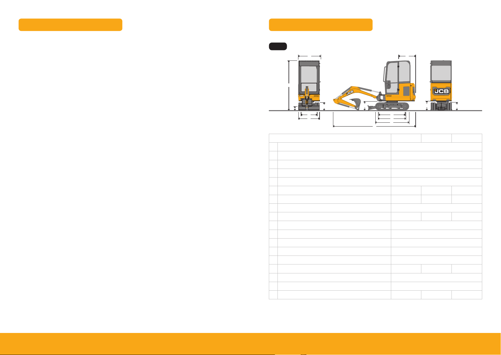
Machine model 18z-1 19c-1 19c-1 EP
A Sprocket idler centres mm 1218
B Track length on ground mm 1220
C Undercarriage overall length – rubber mm 1578
Undercarriage overall length – steel mm 1578
D Kingpost clearance mm 409
E Tailswing radius mm 685 110 3 110 3
F Overall width of superstructure mm 996 996 996
G Height over cab mm 2324
Height over canopy mm 2340 2324 2 324
H Ground clearance mm 162
I Track gauge – Retracted mm 750
Track gauge – Extended mm 1110
J Width over tracks – Retracted mm 980
Width over tracks – Extended mm 133 0
K Transport length with standard dipper mm 3547 3860 3862
L Track height mm 367
M Counterweight clearance mm 434
N Operating mass* kg 1749 1910* * 1943* *
45Please see operator manual for full details.
* Standard machine specification, please see data plate for speci fic machine weight.
* * Cab variant.
18z-1, 19c-1, 19c-1 EP
Operation
Transporting the Machine
Figure 90. Method 3
E
E
Tie Down Points
Operation
Transporting the Machine
Figure 89. Method 2
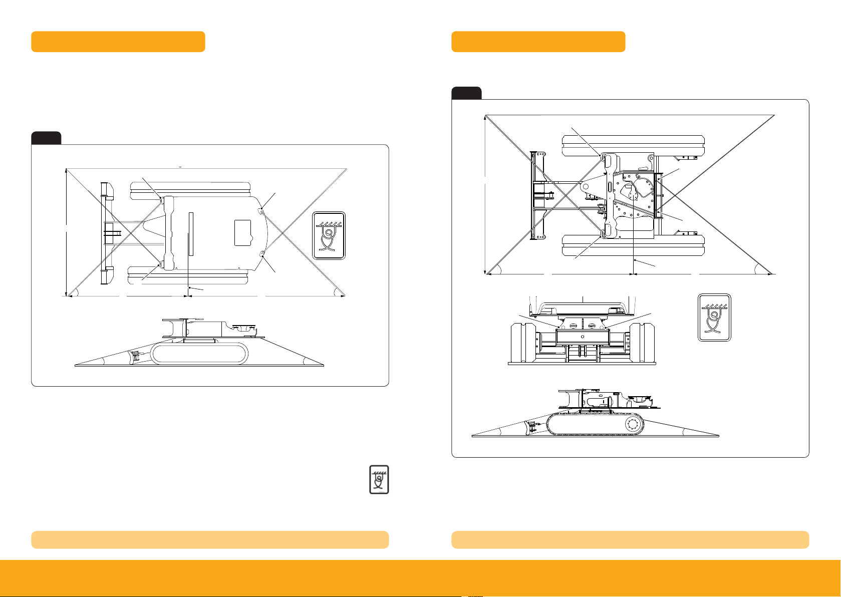
When transporting the machine one of the following three methods should be used:
Method 1
Fig 2
Tie Down Points
Method 2
Fig 3
A
A
H
C D
A
F
E
A Front slew spine tie-down point
C Angle = 35° to 46°
E Angle = 9° to 15°
G Length = 2,720mm to 1,943mm
I Slew ring centre line
I
B Rear slew spine tie-down point
D Angle = 45° to 50°
F Leng th = 2,499mm to 1,846mm
H Length = 2,500mm
J Tie down decal
B
G
J
B
E
Tie Down Posi tion Decal
H
C
B
F
A Front slew spine tie-down point
C Angle = 35° to 46°
E Angle = 9° to 15°
G Length = 2,282mm to 1,670mm
I Slew ring centre line
A
I
B
B Rear slew spine tie-down point
D Angle = 35° to 45°
F Length = 2,499mm to 1,846mm
H Length = 2 ,500mm
J Tie down decal
B
B
G
J
D
REFER TO OPER ATORS MANUAL TRANSPORTING MACHINE REFER TO OPER ATORS MANUAL TRANSPORTING MACHINE
67Please see operator manual for full details.
18z-1, 19c-1, 19c-1 EP
About the Product
Console Switches
Console Switches
Figure 18.
About the Product
Console Switches
About the Product
Console Switches
switch
No LED illumination
Two or three position rocker switch. The switch functions operate when the ignition
switch is in the on position.
Position : 1 = Off
Position : 2 = Boom and front cab work light on
Position : 3 = All work lights on
About the Product
Console Switches
switch
No LED illumination
Two or three position rocker switch. The switch functions operate when the ignition
switch is in the on position.
Position : 1 = Off
Position : 2 = Boom and front cab work light on
Position : 3 = All work lights on
Two or three position rocker switch. The switch functions operate when the ignition
switch is in the on and off positions.
Position : 1 = Off
Position : 2 = Beacon on
Controls isolation switch. Two position momentary rocker switch. Press switch to
activate/de-activate the control.
Position : 1 = Rest position.
Position : 2 = Momentary position (activate/de-activate hydraulic controls).
Three position rocker switch. The switch functions operate when the ignition switch is
in the on position. The wiper will self-park when switched off.
Position : 1 = Off
Position : 2 = On
Position : 3 = Washer on (if installed)
Two position rocker switch. The switch functions operate when the ignition switch is in
the on position and auxiliary has been selected.
Position 1: Bi-directional mode- Double acting attachment
Position 2: Hammer mode- Single acting attachment
About the Product
Console Switches
switch
No LED illumination
Two or three position rocker switch. The switch functions operate when the ignition
switch is in the on position.
Position : 1 = Off
Position : 2 = Boom and front cab work light on
Position : 3 = All work lights on
Two or three position rocker switch. The switch functions operate when the ignition
switch is in the on and off positions.
Position : 1 = Off
Position : 2 = Beacon on
Controls isolation switch. Two position momentary rocker switch. Press switch to
activate/de-activate the control.
Position : 1 = Rest position.
Position : 2 = Momentary position (activate/de-activate hydraulic controls).
Three position rocker switch. The switch functions operate when the ignition switch is
in the on position. The wiper will self-park when switched off.
Position : 1 = Off
Position : 2 = On
Position : 3 = Washer on (if installed)
Lifting Points
Operation
Lifting the Machine
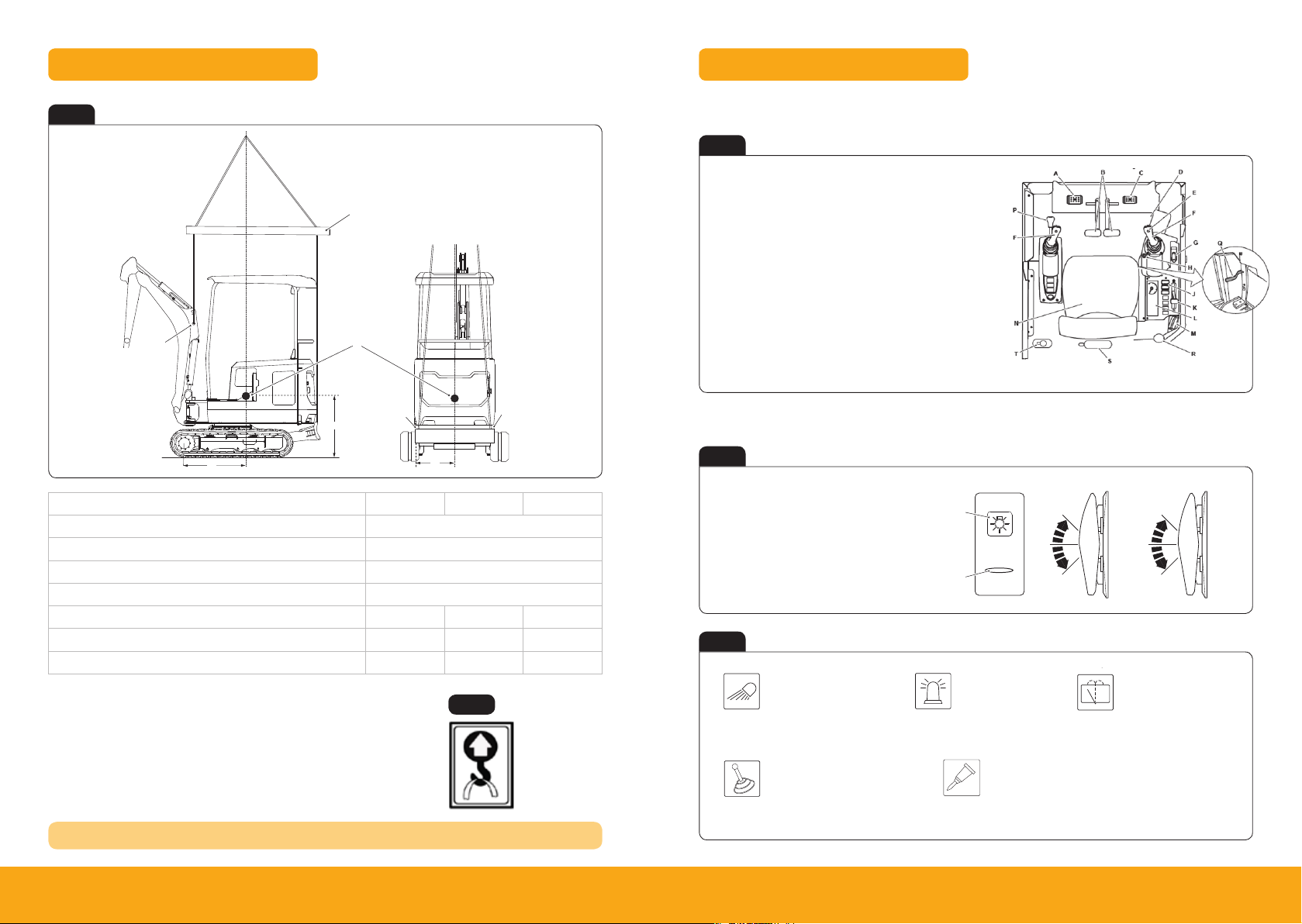
7. Check that the lifting eye is positioned directly above the machine centre of gravity.
Figure 84.
E
Cab & Switch Panel
Fig 4
A
Description 18z-1 19c-1 19c-1 EP
A Boom Lif t Point
B Dozer Blade Lift Point
C Spreader Bar
D Centre of Gravity
E mm 632 792 792
F mm 659 639 639
G mm 525 533 533
F
*COG = Centre of Gravity
The correct lifting positions are identified on the machine by their labels:
REFER TO OPER ATORS MANUAL TRANSPORTING MACHINE
C
D
Operator Station Layout – 18z-1, 19c-1
Fig 6
A Auxiliary pedal
B Track Controls
C Swing left/ right
D Heater Controls
E Horn
F Excavator arm controls
G Dozer control lever
H Ignition switch
J Right console switches
L Instrument panel
M Radio (if installed)
N Operator seat
P Control isolation lever
Q Undercarriage track
extension lever
R Fire extinguisher (18z-1)
S Fire extinguisher (19c-1)
T Window washer bottle
K Hand throttle
B
B
Switch Panel – 18z-1, 19c-1
G
Fig 5
Lifting point
Fig 7
A Graphic symbol
B Light bar
C 3 way position switch
D 2 way position switch / momentary switch
Fig 8
Work Lights
1 Off
2 On (Boom)
3 On (Boom & Cab)
A
B
Beacon
1 Off
2 On (Boom)
C D
1
2
3
1
2
3
Window Wipers
1 Off
2 Intermit tent/
continuos/washer
Position label.
Controls Isolation (2GO)
1 Off
2 Activate/de-activate
hydraulic controls
Bi-Directional and Hammer Mode Selector
1 Bi-directional mode – Double acting
2 Hammer mode – Single acting
89Please see operator manual for full details.
18z-1, 19c-1, 19c-1 EP
 Loading...