

Page 1
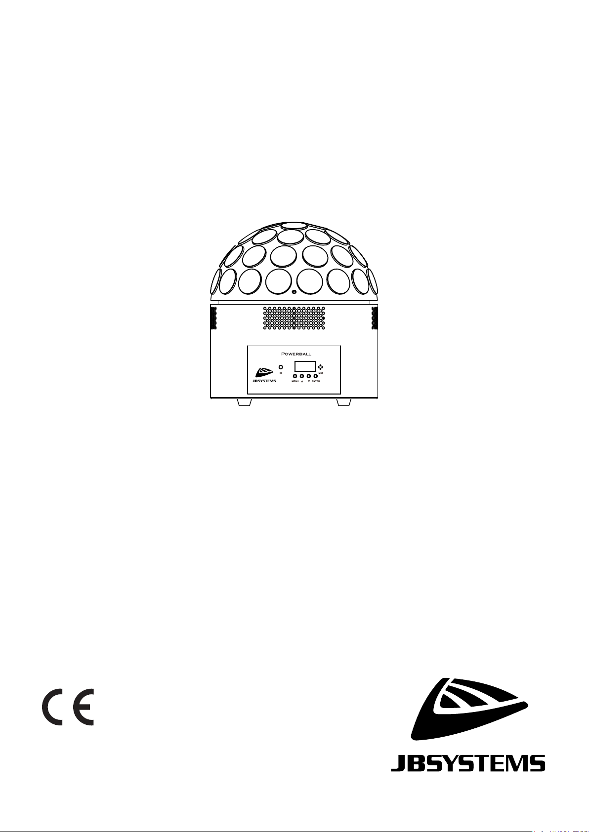
Powerball White
Other languages can be downloaded from:
Version: 1.0
ENGLISH
Operation Manual
WWW.JB-SYSTEMS.EU
Page 2

ENGLISH USER MANUAL
JB SYSTEMS® 1/10 POWERBALL WHITE
OPERATION MANUAL
Thank you for buying this JB Systems® product. To take full advantage of all possibilities and for your own
safety, please read these operating instructions very carefully before you start using this unit.
This device was designed to produce decorative effect lighting and is used in light show systems.
FEATURES
• Powerful 200W LED alternative to the classic mirror ball with pin spots!
• This POWERBALL offers the same kind of effect but with many more possibilities!
• 20x 10-watt Led's (10x Warm White + 10x Cold White) distributed over 4 individually controllable groups.
• Simple and quick installation, easy to use
• Comprehensive DMX control over rotation speed, colors (WW/CW), strobe, etc.
• Or just use the great built-in programs for wonderful, ever-changing light shows.
• Multiple modes of operation:
• DMX-controlled via 1, 3, 4, 8 or 10 channels.
• Standalone: sound activated (internal microphone) or automatic.
• Standalone: controlled via the included IR remote control.
• Several units can be connected in master/slave to create beautiful synchronized shows.
• 3-digit LED screen for easy menu navigation.
• USB connection for wireless DMX control with an optional Briteq® WTR-DMX dongle.
• Multiple units can be easily interconnected via Powercon power in/out.
• Easy truss mounting using the included Omega bracket.
• Reduced height for fixed installation in Cafés and clubs with low ceiling.
BEFORE USE
• Before you start using this unit, please check if there’s no transportation damage. Should there be any, do
not use the device and consult your dealer first.
• Important: This device left our factory in perfect condition and well packaged. It is absolutely necessary
for the user to strictly follow the safety instructions and warnings in this user manual. Any damage caused
by mishandling is not subject to warranty. The dealer will not accept responsibility for any resulting defects
or problems caused by disregarding this user manual.
• Keep this booklet in a safe place for future consultation. If you sell the fixture, be sure to add this user
manual.
Check the contents:
Check if the cardboard box contains the following items:
• POWERBALL WHITE
• IR Remote controller
• Mains cable
• Omega clamp
• Operating instructions
Page 3
ENGLISH USER MANUAL
JB SYSTEMS® 2/10 POWERBALL WHITE
SAFETY INSTRUCTIONS:
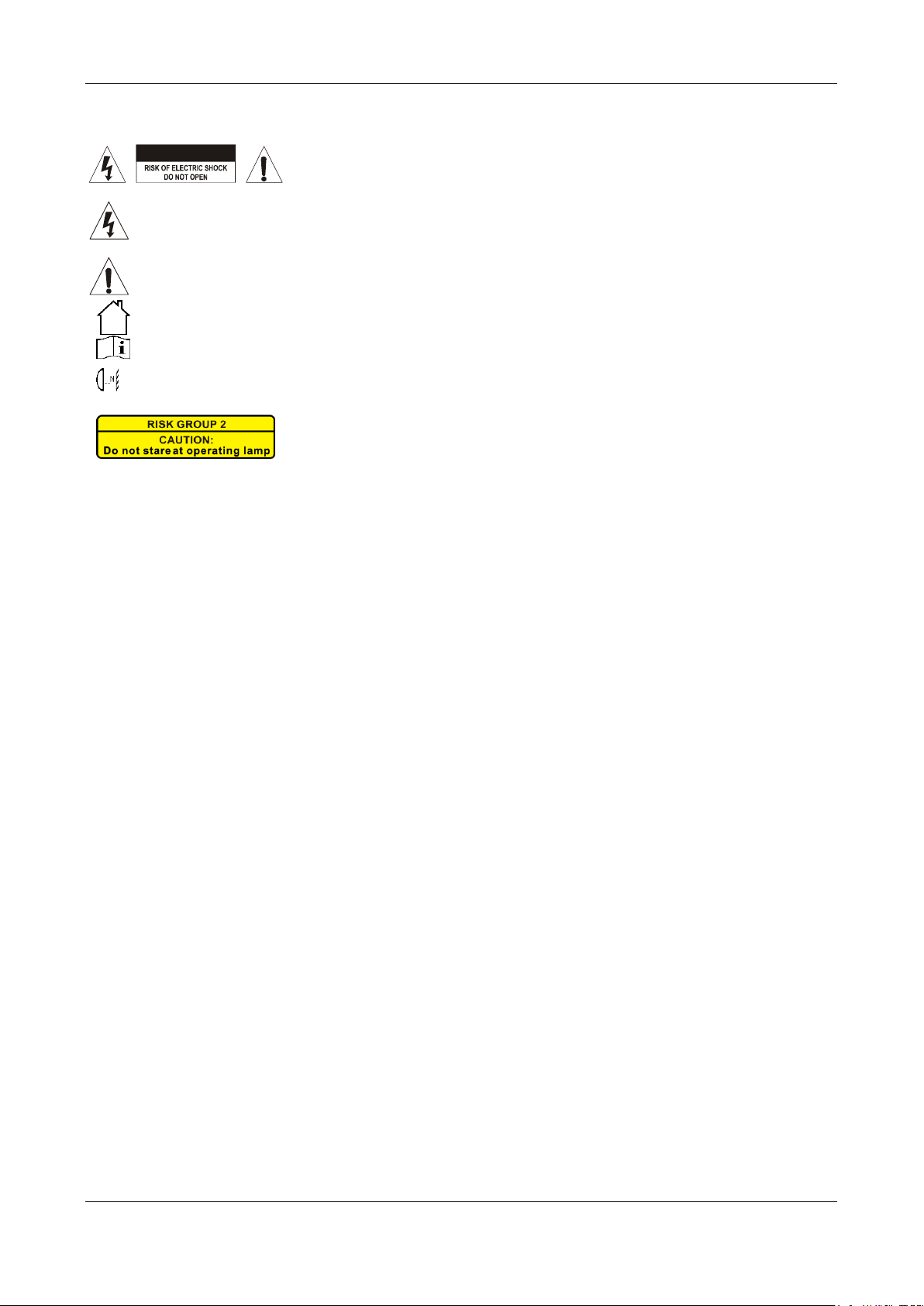
CAUTION: To reduce the risk of electric shock, do not remove the top cover.
No user-serviceable parts inside. Refer servicing to qualified service
personnel only.
The lightning flash with arrowhead symbol within the equilateral triangle is intended to alert the use
or the presence of un-insulated “dangerous voltage” within the product’s enclosure that may be of
sufficient magnitude to constitute a risk of electric shock.
The exclamation point within the equilateral triangle is intended to alert the user to the presence of
important operation and maintenance (servicing) instructions in the literature accompanying this
appliance.
This symbol means: indoor use only.
This symbol means: Read instructions.
This symbol determines: the minimum distance from lighted objects. The minimum distance between
light-output and the illuminated surface must be more than 1 meter.
• To protect the environment, please try to recycle the packing material as much as possible.
• A new light effect sometimes causes some unwanted smoke and/or smell. This is normal and disappears
after some minutes.
• To prevent fire or shock hazard, do not expose this appliance to rain or moisture.
• To avoid condensation to be formed inside, allow the unit to adapt to the surrounding temperatures when
bringing it into a warm room after transport. Condense sometimes prevents the unit from working at full
performance or may even cause damages.
• This unit is for indoor use only.
• Don’t place metal objects or spill liquid inside the unit. Electric shock or malfunction may result. If a foreign
object enters the unit, immediately disconnect the mains power.
• Locate the fixture in a well ventilated spot, away from any flammable materials and/or liquids. The fixture
must be fixed at least 50cm from surrounding walls.
• Don’t cover any ventilation openings as this may result in overheating.
• Prevent use in dusty environments and clean the unit regularly.
• Keep the unit away from children.
• Inexperienced persons should not operate this device.
• The save ambient temperature is between 15° & 40°C. Don’t use this unit at higher ambient temperatures.
• Make sure the area below the installation place is free from unwanted persons during rigging, de-rigging
and servicing.
• Always unplug the unit when it is not used for a longer time or before replacing the bulb or start servicing.
• The electrical installation should be carried out by qualified personal only, according to the regulations for
electrical and mechanical safety in your country.
• Check that the available voltage is not higher than the one stated on the rear panel of the unit.
• The power cord should always be in perfect condition. Switch the unit immediately off when the power cord
is squashed or damaged. It must be replaced by the manufacturer, its service agent or similarly qualified
persons in order to avoid a hazard.
• Never let the power-cord come into contact with other cables!
• This fixture must be earthed to in order comply with safety regulations.
• Don’t connect the unit to any dimmer pack.
• Always use an appropriate and certified safety cable when installing the unit.
• In order to prevent electric shock, do not open the cover. Apart from the lamp and mains fuse there are no
user serviceable parts inside.
• Never repair a fuse or bypass the fuse holder. Always replace a damaged fuse with a fuse of the same
type and electrical specifications!
• In the event of serious operating problems, stop using the fixture and contact your dealer immediately.
• The housing and the lenses must be replaced if they are visibly damaged.
• Please use the original packing when the device is to be transported.
CAUTION: Do not stare at operating lamp.
May be harmful to the eyes.
CAUTION
Page 4
ENGLISH USER MANUAL
JB SYSTEMS® 3/10 POWERBALL WHITE
• Due to safety reasons it is prohibited to make unauthorized modifications to the unit.
Important: Never look directly into the light source! Don’t use the effect in the presence of persons suffering
from epilepsy.
DESCRIPTION:
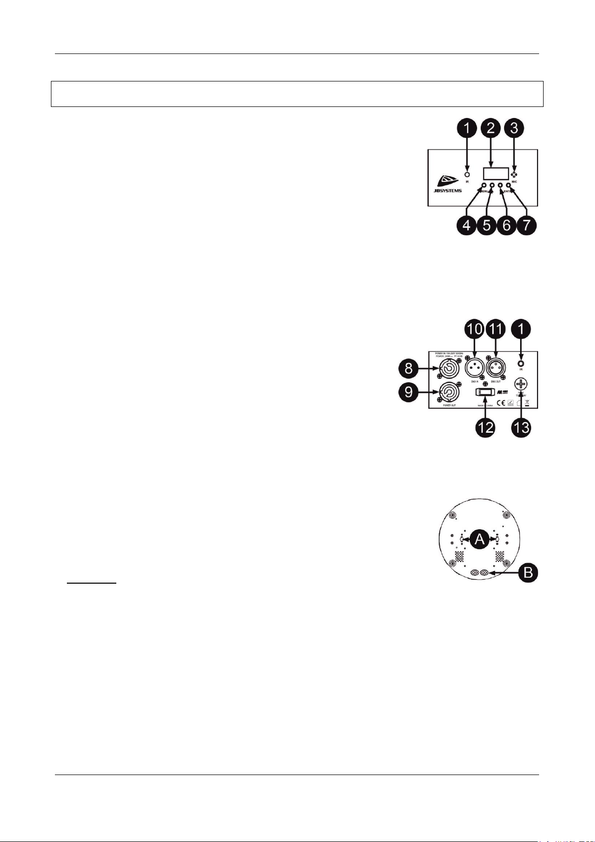
1. IR RECEIVER: point your IR Remote to this area if you want to control the
unit
2. DISPLAY: shows all the necessary information about settings and working
modes.
3. INTERNAL MICROPHONE: is used to synchronize the sound controlled
shows to the beat of the music. You can set the sensitivity of this microphone
in the menu or via the last DMX channel when you use the 8 channel or 10
channel mode.
4. MENU BUTTON: used to browse the different menu options
5. UP BUTTON: to go up in the menu and to increase the values shown on the display
6. DOWN BUTTON: to go back in the menu and to lower the values shown on the display
7. ENTER BUTTON: used to confirm your choice
8. MAINS INPUT: Connect the supplied mains cable here
9. MAINS LINK OUTPUT: use a special Combi Cable to connect this output with the mains input of the
next POWERBALL unit for easier linking
10. DMX INPUT: receives instructions from a DMX-controller (in DMX
mode) or from the Master unit (in Master/Slave mode).
11. DMXOUTPUT: used to connect the unit with the next unit in the DMX
chain.
12. M-DMX INPUT: Please note that this USB-connector is NOT used for
updates or to connect the unit to a PC! Instead this USB-connector
makes it very easy to add wireless DMX to the unit! Just add the
(optional) WTR-DMX DONGLE from BRITEQ® and you will get
wireless DMX! Moreover you will be able to connect other DMXcontrolled equipment to the DMX-output so you can share the wireless
DMX function with all connected units! No extra settings to be made in the setup menu, just follow the
procedure in the user manual supplied with the WTR-DMX DONGLE from BRITEQ®. The separate
WTR-DMX DONGLE is available from WWW.BRITEQ-LIGHTING.COM (order code: 4645)
13. FUSE:
OVERHEAD RIGGING
A. Holes to fix the omega clamp: Take care to properly fix both locks of the
omega clamp
B. Cable passage: can be used to fix an optional safety cable
• Important: The installation must be carried out by qualified service personal
only. Improper installation can result in serious injuries and/or damage to property. Overhead
rigging requires extensive experience! Working load limits should be respected, certified
installation materials should be used, the installed device should be inspected regularly for safety.
• Make sure the area below the installation place is free from unwanted persons during rigging, de-rigging
and servicing.
• Locate the fixture in a well ventilated spot, far away from any flammable materials and/or liquids. The
fixture must be fixed at least 50cm from surrounding walls.
• The device should be installed out of reach of people and outside areas where persons may walk by or be
seated.
• Before rigging make sure that the installation area can hold a minimum point load of 10times the device’s
weight.
• Always use a certified safety cable that can hold 12 times the weight of the device when installing the unit.
This secondary safety attachment should be installed in a way that no part of the installation can drop
more than 20cm if the main attachment fails.
Page 5

ENGLISH USER MANUAL
JB SYSTEMS® 4/10 POWERBALL WHITE
• The device should be well fixed; a free-swinging mounting is dangerous and may not be considered!
• Don’t cover any ventilation openings as this may result in overheating.
• The operator has to make sure that the safety-relating and machine-technical installations are approved by
an expert before using them for the first time. The installations should be inspected every year by a skilled
person to be sure that safety is still optimal.
HOW TO SET UP AND CONTROL THE UNIT
You can operate the unit in several ways:
1) FULL AUTOMATIC STANDALONE MODE:
The effect automatically runs a preprogrammed sequence. Select this mode when only 1 POWERBALL
unit is used (standalone) or when the unit is placed as the first (master) unit in a chain with several
POWERBALL units in Master/Slave mode (see below).
There are different types of standalone modes:
Automatic show mode: this is how to select one of the preprogrammed shows
• Press the [MENU] button until the display shows [Prog].
• Press the [ENTER] button to enter.
• Press the [MENU] button until the display shows [Auto].
• Press the [ENTER] button to enter the setup.
• Use the [UP] and [DOWN] buttons to select fade mode [FAdE] or color jump mode [JuhP]
• Press the [ENTER] button to confirm.
• Use the [UP] and [DOWN] buttons to select the speed of the program (S.1 to S.100)
• Press the [ENTER] button to confirm.
Color mode: used to select a preset of colors:
• Press the [MENU] button until the display shows [CoLo].
• Press the [ENTER] button to enter the setup..
• Use the [UP] and [DOWN] buttons to select the desired color preset: C1=Warm White, C2 = Cold White,
C3 = Warm White + Cold White
• Press the [ENTER] button to confirm.
Manual Color mode: used to manually set the intensity of each color :
• Press the [MENU] button until the display shows [MAnU].
• Press the [ENTER] button to enter the setup. The display shows a value from [C. 0] to [C.100].
• Use the [UP] and [DOWN] buttons to set the intensity of the Cold white led’s
• Press the [ENTER] button to enter the setup. The display shows a value from [W. 0] to [W.100].
• Use the [UP] and [DOWN] buttons to set the intensity of the Warm White white led’s
ROTATION: when you have selected one of the programs above, you can set rotation speed manually.
• Press the [MENU] button until the display shows [ rot].
• Press the [ENTER] button to enter the setup..
• Use the [UP] and [DOWN] buttons to select left rotation, right rotation, no rotation [StoP] or automatic
rotation (combination of right and left rotation)
• Press the [ENTER] button
• Use the [UP] and [DOWN] buttons to select the rotation speed [S 0] to S100]
2) SOUND CONTROLLED STANDALONE MODE:
The POWERBALL runs a preprogrammed sequence to the rhythm of the music. Select this mode when
only 1 POWERBALL is used (standalone) or when the POWERBALL is placed as the first (master) unit in
a chain with several units.
• Press the [MENU] button until the display shows [Snd].
• Press the [ENTER] button: The display shows [Sound]
• Press the [ENTER] button again if you want to set the sound sensitivity of the internal microphone:
• Use the [UP] and [DOWN] buttons to set the sound sensitivity of the internal microphone [u.7] to [u.100]
• Press the [ENTER] button to confirm.
3) MASTER/SLAVE STANDALONE MODE:
Page 6
ENGLISH USER MANUAL
JB SYSTEMS® 5/10 POWERBALL WHITE
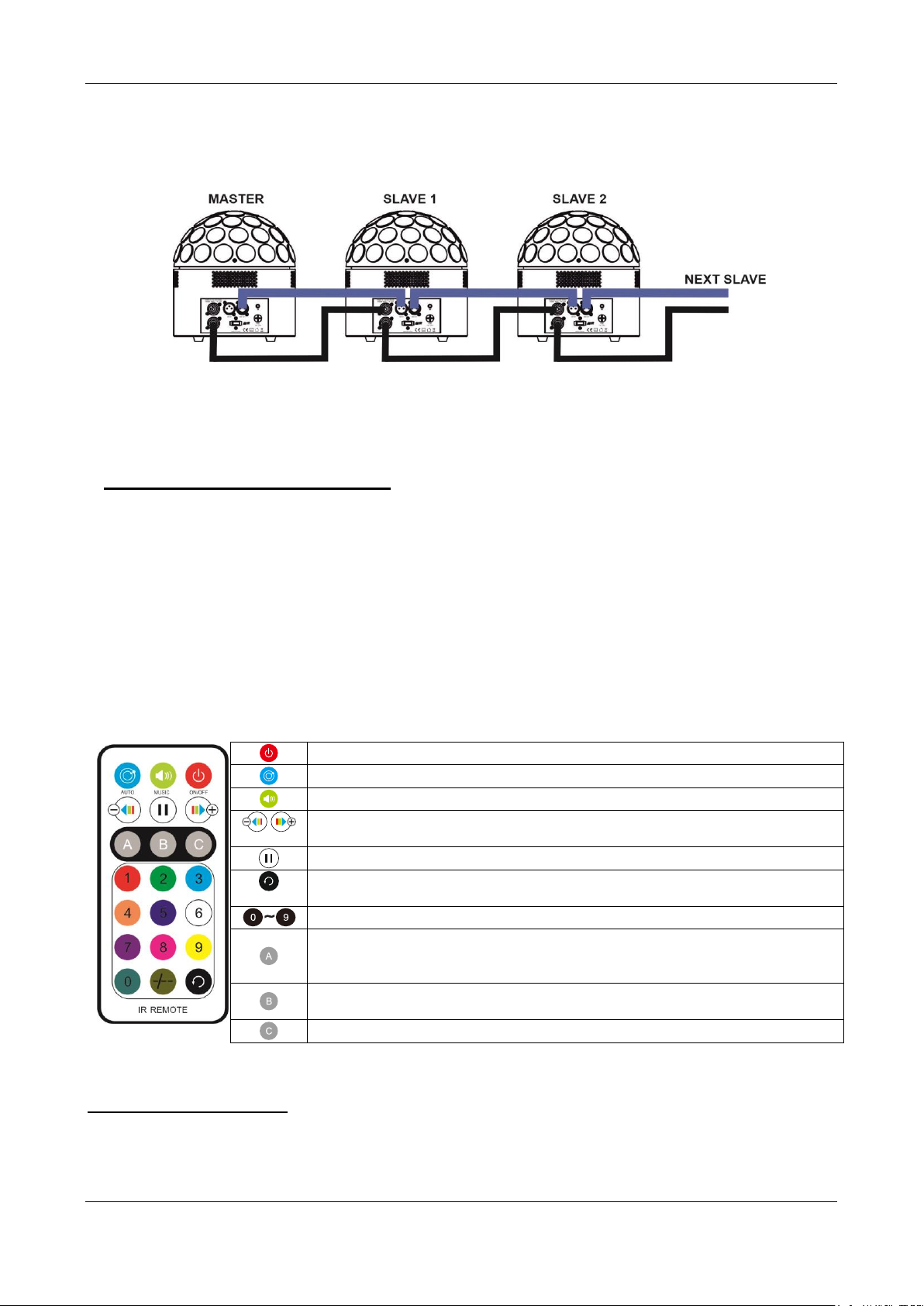
When you have several POWERBALL units and you want them to all work synchronously, you can work in
the so called master/slave mode. To do this, just daisy-chain all the units and make the settings of the
desired automatic or sound controlled program in the first unit of the chain (see description above). This
unit is called the Master unit. Now put all the other units in slave mode. Once this is done, the “slave” units
will follow the orders of the Master unit, so they work in perfect synchronicity.
To set a unit in slave mode:
• Press the [MENU] button until the display shows [SLA].
• Press the [ENTER] button to enter this mode.
• [SLAU] will appear on the display
• Press the [ENTER] button to confirm the slave mode.
4) CONTROLLED VIA THE IR REMOTE:
The standalone functions of the POWERBALL can be controlled via the supplied IR remote controller.
Important: to be able to use the IR remote controller, the IR remote receiver has to be switched on in the
unit.
This is how to do this:
• Press the [MENU] button until the display shows [SET].
• Press the [ENTER] button to enter this part of the menu with extra options.
• Use the [UP/DOWN] buttons to browse the extra functions in this System menu
• When [ir] appears on the screen, press [ENTER]
• Use the [UP / DOWN] button to select the desired mode:
o ON = IR remote receiver activated.
o OFF = IR remote receiver deactivated.
• Press the [ENTER] button to confirm
When the receiver is switched ON in the unit, you can use the IR remote control
5) CONTROLLED VIA DMX:
The POWERBALL can be controlled by any standard DMX-controller in 5 different DMX-modes via 1, 3, 4,
8 or 10 channels
To switch the effect On or Off
To select the automatic programs
To select sound controlled programs
Use these buttons to modify the program speed, audio sensitivity, rotation
speed or rotation direction (depending of the selected feature)
To pause the program
To toggle between color jump and color fade when the automatic programs
are selected
Color selection: 3=CW, 6=WW, 9=CW+WW
Select the speed of the automatic programs or the microphone sensitivity of
the Sound controlled programs and use the – and + buttons to modify the
setting
Select the rotation direction and use the – and + buttons to modify the
setting
Select the rotation speed and use the – and + buttons to modify the setting
Page 7
ENGLISH USER MANUAL
JB SYSTEMS® 6/10 POWERBALL WHITE
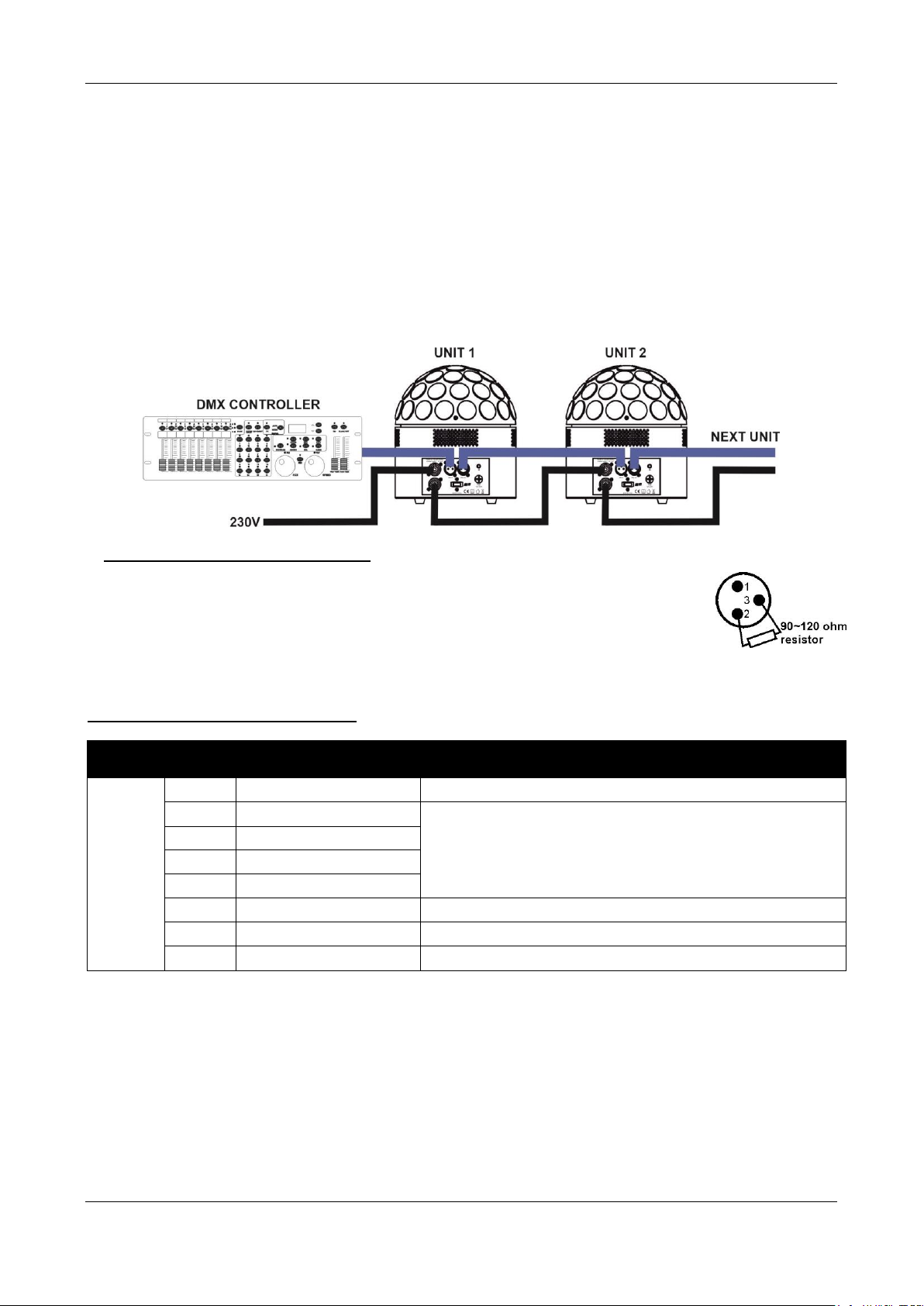
• Connect the DMX input of the POWERBALL to the DMX output of the previous unit in the chain or
directly to the DMX-output of your controller.
• Press the [MENU] button until the display shows [dMX].
• Press the [ENTER] button to enter this mode
• The actual DMX address is shown on the display.
• Press the [ENTER] button again
• The channel mode is shown on the display
• Use the [UP/DOWN] buttons to select the desired DMX-mode. (1Ch, 3Ch, 4Ch, 8Ch or 10Ch). See the
DMX charts below
• Press the [ENTER] button to confirm your choice.
• Now you can use the [UP/DOWN] buttons to set the DMX address. [dxxx]
• Press the [ENTER] button to confirm your choice.
Some more information on DMX512:
The DMX-protocol is a widely used high speed signal to control intelligent light
equipment. You need to “daisy chain” your DMX controller and all the connected light
effects with a good quality XLR M/F balanced cable. To prevent strange behavior of the
light effects, due to interferences, you must use a 90Ω to 120Ω terminator at the end of
the chain. Never use Y-splitter cables, this simply won’t work!
Each effect in the chain needs to have its proper starting address so it knows which commands from the
controller it has to decode.
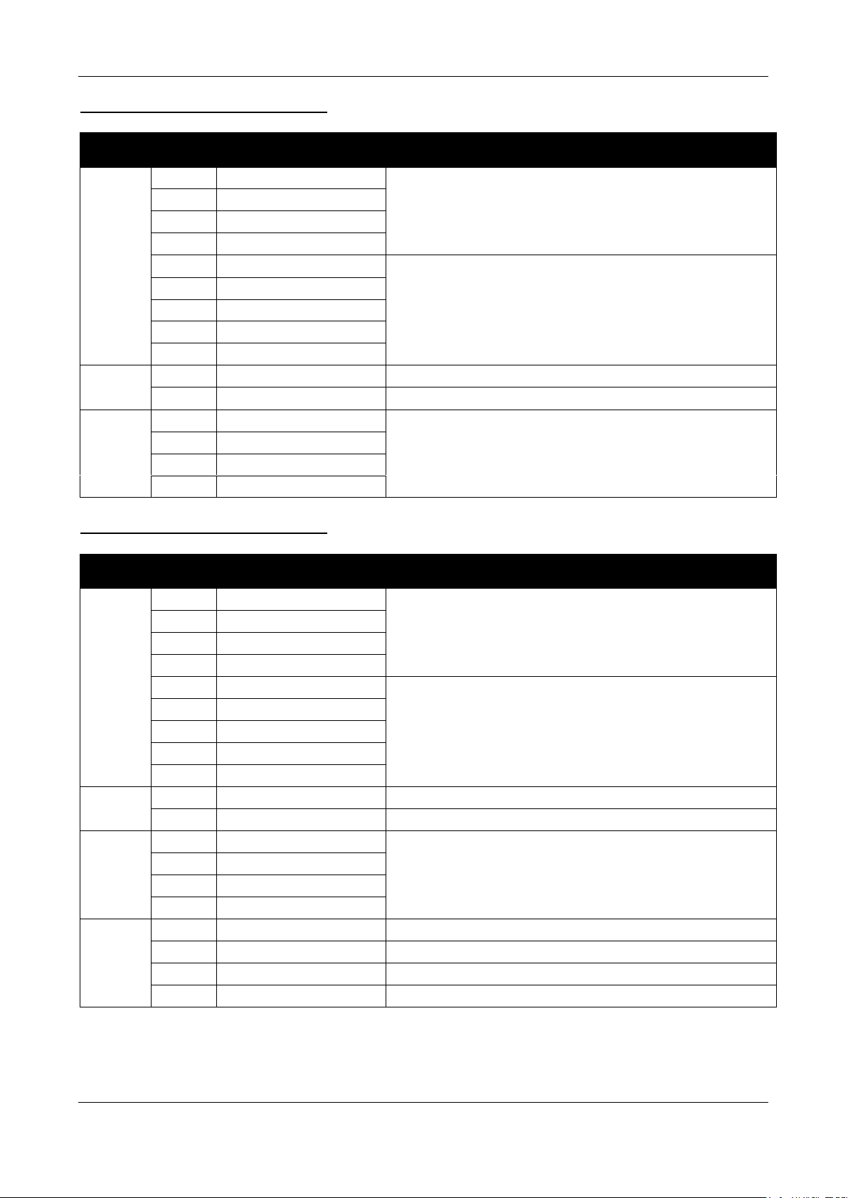
1 CHANNEL DMX-CONFIGURATION:
DMX
Channel
DMXvalue
function
remarks
1
000-005
Blackout
No Rotation
006-036
Cold White
Slow rotation
037-068
Warm White
069-100
All White
101-164
Auto Program
165-196
Sound Program
No rotation
197-228
Sound Program
Slow rotation
229-255
Sound Program
Medium rotation
Page 8
ENGLISH USER MANUAL
JB SYSTEMS® 7/10 POWERBALL WHITE
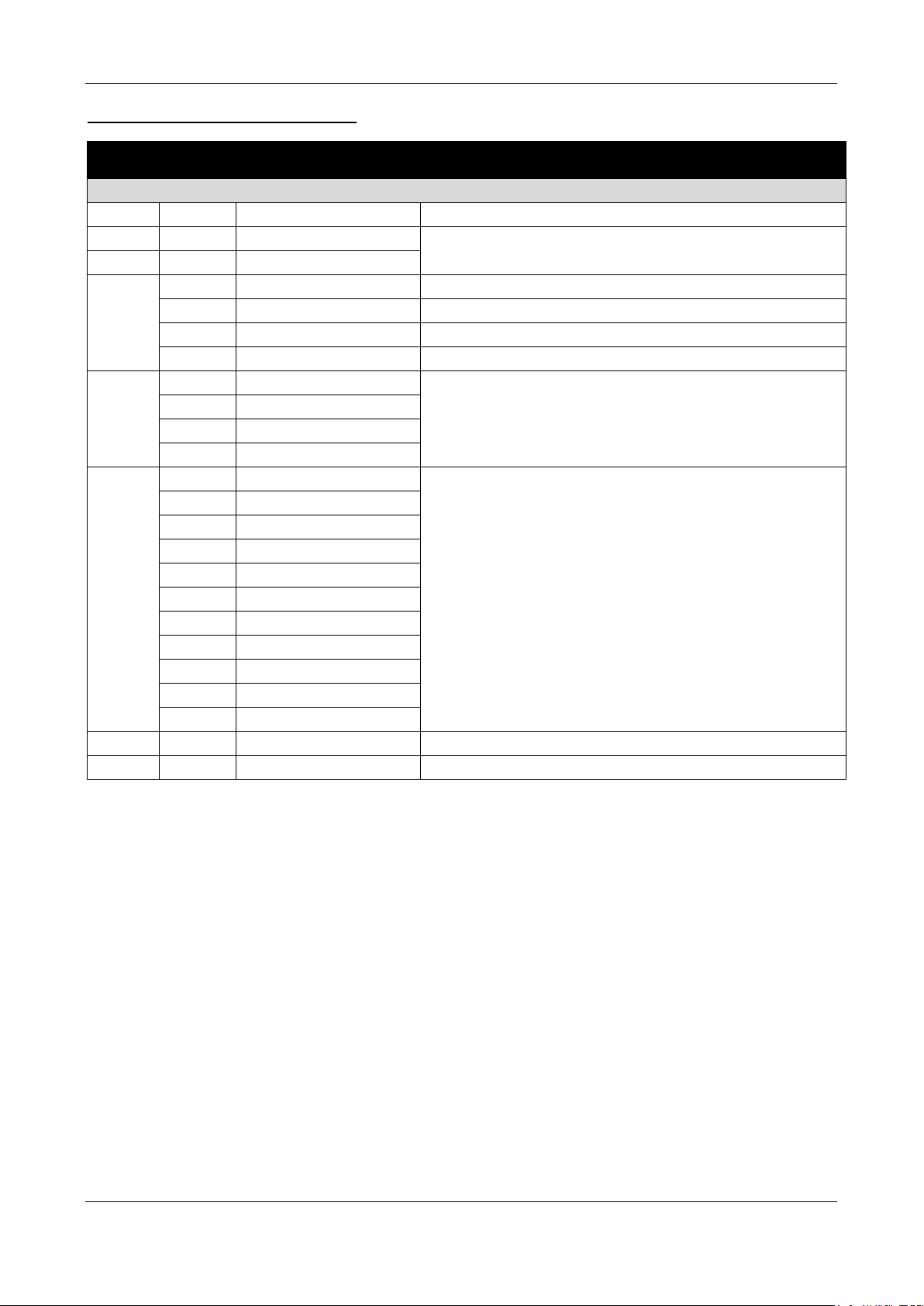
3 CHANNEL DMX-CONFIGURATION:
DMX
Channel
DMXvalue
function
remarks
1
000-005
Blackout
006-033
Cold White
Static Color
034-061
Warm White
DMX Channel 2 can not be used
062-117
All White
118-145
Program 1
Preprogrammed Shows
You can use DMX channel 2
for Speed or Sound control
146-173
Program 2
174-201
Program 3
202-229
Program 4
230-255
Program 5
2
000-250
Speed Control
Speed of the selected program via channel 1
251-255
Sound Control
Sound control for the selected program via channel 1
3
000
No rotation
Motor Control
001-127
Clockwise rotation
128
No rotation
129-255
Anticlockwise rotation
4 CHANNEL DMX-CONFIGURATION:
DMX
Channel
DMXvalue
function
remarks
1
000-005
Blackout
Static Color
DMX Channel 2 can not be used
006-033
Cold White
034-061
Warm White
062-117
All White
118-145
Program 1
Preprogrammed Shows
You can use DMX channel 2
for Speed or Sound control
146-173
Program 2
174-201
Program 3
202-229
Program 4
230-255
Program 5
2
000-250
Speed Control
Speed of the selected program via channel 1
251-255
Sound Control
Sound control for the selected program via channel 1
3
000
No rotation
Motor Control
001-127
Clockwise rotation
128
No rotation
129-255
Anticlockwise rotation
000-005
No strobe
006-127
Random strobe
128-250
Normal Strobe Speed
Standard strobe (slow to fast)
251-255
Sound Strobe
Page 9
ENGLISH USER MANUAL
JB SYSTEMS® 8/10 POWERBALL WHITE
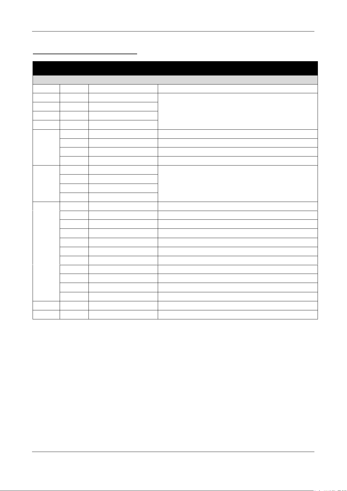
8 CHANNEL DMX-CONFIGURATION:
DMX
Channel
DMXvalue
function
remarks
RGB Projector control
1
000-255
DIMMER
GENERAL DIMMER
2
000-255
CW
MANUAL COLOR
3
000-255
WW
4
000-005
No strobe
006-127
Random strobe
128-250
Normal Strobe Speed
Standard strobe (slow to fast)
251-255
Sound Strobe
5
000
No rotation
Motor
001-127
Clockwise rotation
128
No rotation
129-255
Anticlockwise rotation
6
000-005
Auto mode OFF
Manual Color Channels 2 to 5 can be used
006-030
Auto prog 01
031-055
Auto prog 02
066-080
Auto prog 03
081-105
Auto prog 04
106-130
Auto prog 05
131-155
Sound prog 01
156-180
Sound prog 02
181-205
Sound prog 03
206-230
Sound prog 04
231-255
Sound prog 05
7
000-255
Program Speed
Speed control for the programs of dmx channel 6
8
000-255
Sound Sensitivity
Used for the sound controlled color programs & strobe
Page 10
ENGLISH USER MANUAL
JB SYSTEMS® 9/10 POWERBALL WHITE
10 CHANNEL DMX-CONFIGURATION:
DMX
Channel
DMXvalue
function
remarks
RGB Projector control
1
000-255
DIMMER
GENERAL DIMMER
2
000-255
Dimmer CW 1
MANUAL COLOR
3
000-255
Dimmer CW 2
4
000-255
Dimmer WW 1
5
000-255
Dimmer WW 2
6
000-005
No strobe
006-127
Random strobe
128-250
Normal Strobe Speed
Standard strobe (slow to fast)
251-255
Sound Strobe
7
000
No rotation
Motor
001-127
Clockwise rotation
128
No rotation
129-255
Anticlockwise rotation
8
000-005
Auto mode OFF
Manual Color Channels 2 to 5 can be used
006-030
Auto prog 01
031-055
Auto prog 02
066-080
Auto prog 03
081-105
Auto prog 04
106-130
Auto prog 05
131-155
Sound prog 01
156-180
Sound prog 02
181-205
Sound prog 03
206-230
Sound prog 04
231-255
Sound prog 05
9
000-255
Program Speed
Speed control for the programs of dmx channel 8
10
000-255
Sound Sensitivity
Used for the sound controlled color programs & strobe
Extra functions in the menu
• Press the [MENU] button until the display shows [SEt].
• Press the [ENTER] button if you want to enter this part of the menu with extra options.
• Use the [UP/DOWN] buttons to browse the extra functions in this System menu
o [ir] = Infra Red Remote controller: with this function you can deactivate the infra-red
remote controller receiver.
▪ Press the [ENTER] button to enter the option settings
▪ Use the [UP / DOWN] button to select the desired mode:
• ON = IR remote receiver activated.
• OFF = IR remote receiver deactivated.
o [rESt] = Factory Reset. This function can be used to reset all the settings of the unit to the
original factory settings
▪ Use the [UP / DOWN] button to confirm if you want to do the reset or not
• YES = the reset will be executed as soon as you press the [ENTER] button.
▪ Press the [ENTER] button.
Page 11

ENGLISH USER MANUAL
JB SYSTEMS® 10/10 POWERBALL WHITE
MAINTENANCE
• Make sure the area below the installation place is free from unwanted persons during servicing.
• Switch off the unit, unplug the mains cable and wait until the unit has been cooled down.
During inspection the following points should be checked:
• All screws used for installing the device and any of its parts should be tightly fastened and may not be
corroded.
• Housings, fixations and installations spots (ceiling, truss, suspensions) should be totally free from any
deformation.
• When an optical lens is visibly damaged due to cracks or deep scratches, it must be replaced.
• The mains cables must be in impeccable condition and should be replaced immediately when even a
small problem is detected.
• In order to protect the device from overheat the cooling fans (if any) and ventilation openings should be
cleaned monthly.
• The interior of the device should be cleaned annually using a vacuum cleaner or air-jet.
• The cleaning of internal and external optical lenses and/or mirrors must be carried out periodically to
optimize light output. Cleaning frequency depends on the environment in which the fixture operates: damp,
smoky or particularly dirty surroundings can cause greater accumulation of dirt on the unit’s optics.
• Clean with a soft cloth using normal glass cleaning products.
• Always dry the parts carefully.
• Clean the external optics at least once every 30 days.
• Clean the internal optics at least every 90 days.
Attention: We strongly recommend internal cleaning to be carried out by qualified personnel!
SPECIFICATIONS
This device carries the prescribed CE marking. It was tested for this purpose in a specialized CE lab and fully
complies with all currently valid European and national standards.
The corresponding CE conformity declarations can be found on the product page of this product on our
website.
Mains Input: AC 100~240V, 50/60Hz
Fuse: 250V 2A slow blow (20mm glass)
Max. Total Power consumption: 200W
Sound Control: Internal microphone
DMX connections: 3pin XLR male / female
DMX channels: 1, 3, 4, 8 or 10 channels
LED power: 200 W
20x 10 Watt Led’s (10x Warm White + 10x Cold White)
Working temperature: 10°C to 40°C
Dimensions: 242 x 242 x 275mm
Weight: 4.65kg
All the information is subject to change without prior notice
You can download the latest version of this user manual on our website: www.jb-systems.eu
Page 12
202
4
 Loading...