

Page 1
Operation Manual
Mode d'emploi
Gebruiksaanwijzing
Bedienungsanleitung
Manual de instrucciones
Version: 1.0
The Power Source for DJ’s
WWW.BEGLEC.COM
Copyright © 2004 by BEGLEC cva.
Reproduction or publication of the content in any manner, without express permission of the publisher, is prohibited.
Page 2
ENGLISH OPERATION MANUAL
JB SYSTEMS 1/30 MX4 Mk2
OPERATION MANUAL
FEATURES
• 11 inputs on 4 channels (7line, 3phones, 1micro)
• 1 DJ micro with talkover
• Gain, treble, mid, bass controls on all channels
• Assignable and easy replaceable crossfader
• High quality, easy gliding “steel rail” DJ faders
• 2 Master outputs, master1 with balance control
• Master1 with balanced XLR outputs
• LED VU-meters on PFL and masters
• Beat leds help you to find the right cadence
• Crossfader starts for compatible CD players
• Pre-fade listening with cue mix option
BEFORE USE
Check the contents:
Check that the carton contains the following items:
• MX4 Mk2 Mixer
• Operating instructions
ENGLISH OPERATION MANUAL
JB SYSTEMS 2/30 MX4 Mk2
SAFETY INSTRUCTIONS:
CAUTION: To reduce the risk of electric shock,
do not remove any cover. No user-serviceable
parts inside. Refer servicing to qualified service
personnel only.
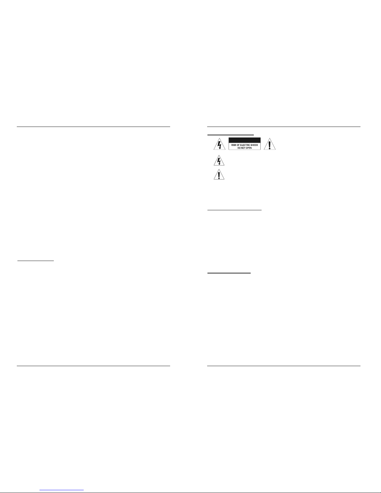
The lightning flash with arrowhead symbol within the equilateral triangle is
intended to alert the use or the presence of un-insulated “dangerous voltage”
within the product’s enclosure that may be of sufficient magnitude to
constitute a risk of electric shock.
The exclamation point within the equilateral triangle is intended to alert the
user to the presence of important operation and maintenance (servicing)
instructions in the literature accompanying this appliance.
To prevent fire or shock hazard, do not expose this appliance to rain or moisture. Do not
place metal objects or spill liquid inside the turntable. Electric shock or malfunction may
result.
INSTALLATION GUIDELINES:
• Install the unit in a well-ventilated location where it will not be exposed to high
temperatures or humidity.
• Placing and using the unit for long periods near heat-generating sources such as
amplifiers, spotlights, etc. will affect its performance and may even damage the unit.
• The unit can be mounted a rack. Attach the unit using the 4 screw holes on the front
panel. Be sure to use screws of the appropriate size. (screws not provided)
Take care to minimize shocks and vibrations during transport.
• When installed in a booth or flight case, please make sure to have good ventilation to
improve heat evacuation of the unit.
• To avoid condensation to be formed inside, allow the unit to adapt to the surrounding
temperatures when bringing it into a warm room after transport. Condense sometimes
prevents the unit from working at full performance.
CLEANING THE MIXER:
Clean by wiping with a polished cloth slightly dipped with water. Avoid getting water inside
the unit. Do not use volatile liquids such as benzene or thinner which will damage the unit.
CONNECTIONS
Except for microphones, headphone and master outputs, all connections are cinch. Use
good quality cinch-cinch cables to prevent bad audio quality. (example: JB Systems code:
2-0370)
For more information on connections, please refer to the next chapter.
Be sure to turn off the mixer before you make changes to the different connections.
In this manual we talk about “line inputs”. This is a global name for inputs with a level
between 750mV and 2V. This includes tuners, videos, CD-players, etc.
CAUTION
Page 3
ENGLISH OPERATION MANUAL
JB SYSTEMS 3/30 MX4 Mk2
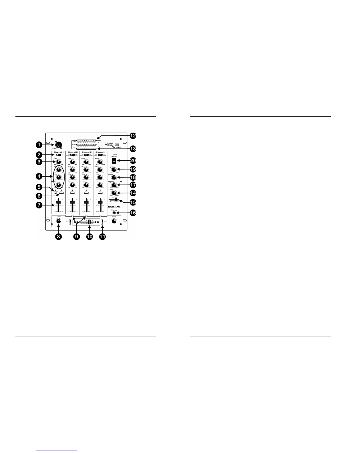
CONTROLS AND FUNCTIONS
1. DJ MIC INPUT JACK: Accepts an unbalanced microphone with XLR connector. You
can find the ¼” mono jack on the rear of the mixer (29). This input is mainly used as
DJ-microphone. The talkover does not affect the signal level of this input.
2. INPUT SOURCE SELECTOR: Used to select the correct input on each channel:
Phono, line, aux or mic. On some channels there are additional input selectors on the
back.
Hint: Line, Aux, CD, Tuner, etc… are different names for inputs with almost the same signal levels.
3. GAIN LEVEL: Adjusts the input level on each channel. Use this control to adjust the
level on the VU-meter at about 0dB.
4. 3-BAND TONE CONTROLS: The frequency of each channel can be controlled
separately over a range from -26dB to +12dB. In the center position the tone control is
flat. (switched off)
5. TALKOVER: Use this switch to automatically mute the input channels 2 to 4 while you
are talking through the DJ microphone.
6. PFL SELECTOR: Used to select this channel to be monitored via the headphones
output. Pressing multiple Cue-buttons makes it possible to derive a mixed sound from
the selected sources.
7. CHANNEL FADER: Used to set the level of each channel separately.
8. CROSSFADER ASSIGN: Selects the input channels to be used with the crossfader
(10). When set to “0” the crossfader is switched off.
ENGLISH OPERATION MANUAL
JB SYSTEMS 4/30 MX4 Mk2
9. BEAT LEDS: These leds switch on and off to the rhythm of the beat. These leds help
you to find the right cadence.
10. CROSSFADER: With this fader you can mix over between the channels you selected
with the crossfader assign selectors (8). The crossfader only works when you move
the selected channel faders (7) to the desired level! The crossfader also integrates the
optical fader starts. See the next chapter for more information on this issue.
11. FADER START ON/OFF SWITCH: When you have a compatible CD-player
connected to the fader control connectors, you can control its start/stop (re-cue)
functions with the cross fader. With this switch you can turn the fader start control on
and off.
12. MASTER1 VU METERS: Monitors the output level of master1. Make sure the levels
do not exceed 0dB (or 100%). The audio risks to be distorted when the signal level
comes in the red zone of the VU-meter.
13. PFL VU METERS: Monitors the level of the channel you selected with the PFL-switch
(6). Make sure the levels do not exceed 0dB (or 100%).
14. CUE LEVEL: Used to control the output level of the headphone output.
15. CUE MIX: With this fader you can mix the master output and any of the input channels
through the headphone output (16):
• Put the fader in the extreme left position to monitor a selected PFL signal (6).
• Put the fader in the extreme right position to hear the master output.
• Put the fader in any other position to hear a mix of the two signals.
This option makes it possible to check your mix before you put it on the master output.
16. HEADPHONE jack: You can monitor all inputs/outputs when you connect any modern
stereo headphone to this 6.3mm jack.
17. MASTER1 LEVEL: Used to adjust the level of the balanced Master1 output.
18. BALANCE MASTER1: used to adjust the balance between left and right output on
Master1.
19. MASTER2 LEVEL: Used to adjust the level of the unbalanced Master2 output.
20. POWER switch: Used to turn the power of the mixer on and off. The blue led is lit
when the mixer is turned on.
Page 4
ENGLISH OPERATION MANUAL
JB SYSTEMS 5/30 MX4 Mk2
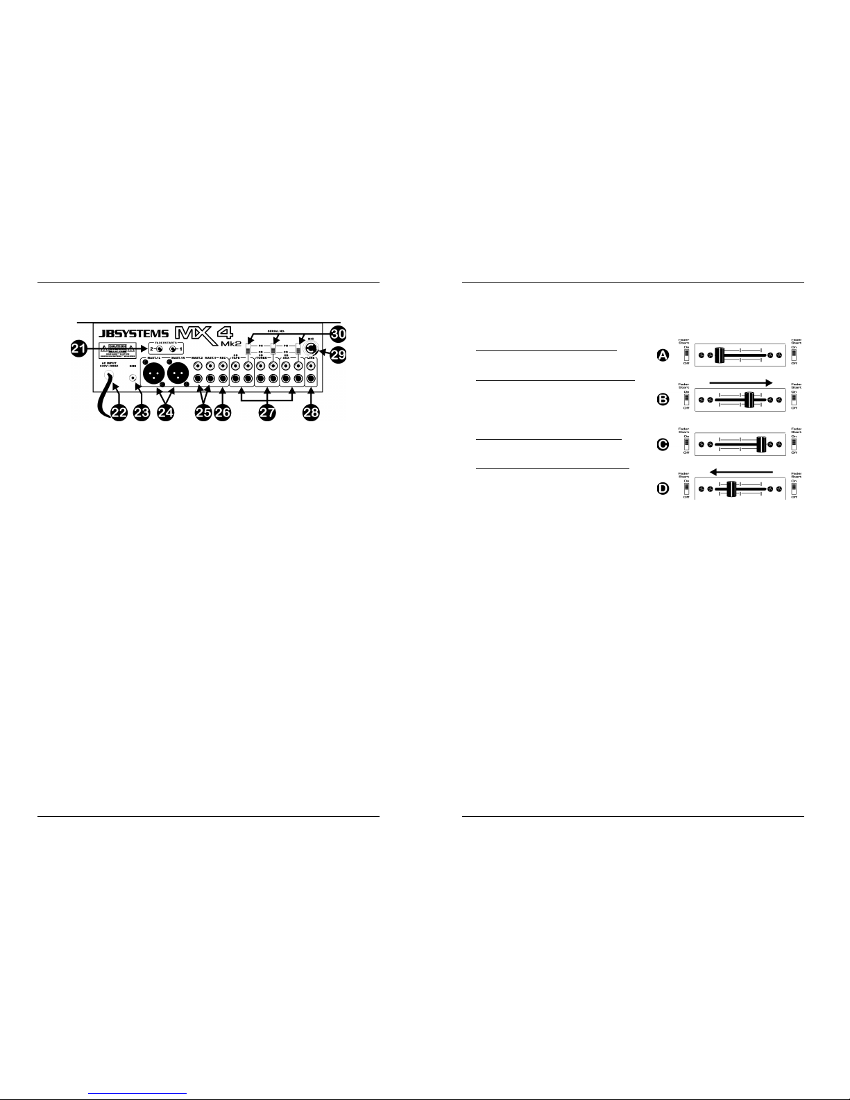
REAR PANEL
21. FADER CONTROL: When connected to these inputs, compatible CD-players can be
controlled by the fader starts of this mixer.
22. MAINS CABLE: connect this cable to a 230V/50Hz mains outlet. Before use, inspect
the cable to be sure it’s not damaged!
23. GROUND (GND) CONNECTION: Many Turntables have a GND-connection. It is
preferable to connect this signal ground to the GND-connector. If your turntable does
not have a ground wire, you don’t have to use this connector.
24. MASTER1 BALANCED OUTPUT: The XLR-connectors can be used to connect this
mixer to any balanced amplifier input, using special balanced signal cables.
25. MASTER UNBALANCED OUTPUTS: The “mast.1” output has the same output signal
as the balanced master output(24) but unbalanced. The “mast.2” output carries the
same signal but can be controlled independently by the master2 level (19). Use the
outputs to connect unbalanced amplifiers.
26. RECORD OUTPUT: Carries the same signal as the master outputs but is not
influenced by the master level, balance and mono/stereo controls. Used to connect
analog recording equipment.
27. INPUT CHANNELS: each used to connect two different line level audio signals. Refer
to switch (30) to change one line input to phono level. The input source selector (2) on
the front determines which input will be active.
28. LINE INPUT CHANNEL1: used to connect a line level audio signal to channel1.
29. MIC INPUT: ¼” mono jack alternative to the XLR microphone input on the front (1).
30. PHONO/CD SWITCH: This switch makes it possible to switch between the CD and
phono level inputs on channels 2, 3 and 4.
ENGLISH OPERATION MANUAL
JB SYSTEMS 6/30 MX4 Mk2
CROSSFADER STARTS
The crossfader integrates the optical fader start switches. These fader starts are
compatible with all current JB Systems CD-players. This is how it works:
A. CROSSFADER IN LEFT POSITION:
CD-player connected to fader start connector
1 is playing, the other CD-player is paused.
B. CROSSFADER MOVES TO THE RIGHT:
CD-player connected to fader start connector
1 stops playing, returns to its previously
programmed cue point and waits in pause.
The other CD-player starts playing from its
previously programmed cue point.
C. CROSSFADER IN RIGHT POSITION:
CD-player connected to fader start connector
2 is playing, the other CD-player is paused.
D. CROSSFADER MOVES TO THE LEFT:
CD-player connected to fader start connector
2 stops playing, returns to its previously
programmed cue point and waits in pause.
The other CD-player starts playing from its
previously programmed cue point.
Important: Both fader start switches must be in “ON” position!
SPECIFICATIONS
Power Supply: AC 230 V, 50Hz
Frequency response: 20-20.000Hz (+/-2dB)
THD + noise: <0.09% @ 1kHz, 0dB
S/N Ratio (IHF-A): >86dB @ 1kHz.
Micro inputs: 1.5mV @ 10kΩ
Line/CD inputs: 150mV @ 22kΩ
Phono inputs: 3mV @ 47kΩ
Record output: 775mV @ 600Ω
Master A/B output: 1.5V @ 4k7Ω unbal.
Master A/B output: 850mV @ 600Ω bal.
Talkover: 0dB Æ -15dB
Tone controls: +12dB / -26dB
Headphone: 1.5V@33Ω
Dimensions: 294(W) x 350(H) x 95(D) mm
Weight: 4.8kg
Page 5

FRANCAIS MODE D’EMPLOI
JB SYSTEMS 7/30 MX4 Mk2
MODE D'EMPLOI
CARACTERISTIQUES
• 11 entrées sur 4 canaux (7line, 3phonos, 1micro)
• 1 micro DJ avec talkover
• Contrôle du Gain, des aigus, médiums et basses sur tous les canaux
• Crossfader assignable, facilement remplaçable
• Curseurs DJ du type «steel rail» de haute qualité, glissant facilement
(curseur doté de rails en acier pour une plus longue durée de vie)
• 2 sorties Master, master 1 avec contrôle de balance
• Master1 avec sorties XLR symétriques
• VU-mètres LED sur le PFL et les masters
• Beat leds vous aident à trouver la bonne cadence
• Démarrage par Crossfader pour les lecteurs CD compatibles
• Pré écoute « Pre-fader » avec option cue mix
AVANT L'UTILISATION
Vérifier le contenu:
Vérifiez que l'emballage contienne les différents éléments:
• Unité de mixage MX4 Mk2
• Mode d'emploi
FRANCAIS MODE D’EMPLOI
JB SYSTEMS 8/30 MX4 Mk2
CONSEILS DE SECURITE:
ATTENTION: Afin d'éviter tout risque
d'électrocution, ne pas soulever le châssis de
l'appareil. L'intérieur ne contient aucune pièce
remplaçable par l'utilisateur. Confier l'appareil à
un service technique compétent..
Ce symbole attire l'attention de l'utilisateur sur la présence de 'voltage
dangereux' à l'intérieur du couvercle. Se voltage est suffisamment élevé pour
constituer un risque d'électrocution.
Ce symbole vous averti de la présence d'instructions importantes concernant
l'utilisation et l'entretient accompagnant cet appareil.
Afin de prévenir tout risque d'incendies et d'électrocutions, ne pas exposer ce appareil à
la pluie ou à l'humidité.
Ne pas insérer d'objets métalliques et ne pas verser de liquides dans l'appareil. Il pourrait
en résulter des électrocutions ou des dysfonctionnements.
CONSEILS D'INSTALLATION:
• Installer l'appareil dans un lieu bien aéré, à l'abri de l'humidité et des fortes
températures.
• Placer et utiliser l'appareil à proximité de sources de chaleur telles que spots, amplis,…
pourrait affecter ses performances et même endommager l'appareil.
• L'appareil peut être installé dans un rack. Fixer l'appareil en utilisant les 4 trous pour vis
sur la face avant. Assurez-vous d'utiliser des vis de la bonne dimension (vis non
fournies). Essayez d'éviter les vibrations et les coups lors du transport.
• En cas d'installation dans un 'flight case', assurer une bonne ventilation afin d'évacuer
la chaleur produite par l'appareil.
• Pour éviter la condensation à l'intérieur, laisser l'appareil s'adapter à la nouvelle
température ambiante après le transport. La condensation peut altérer les
performances de l'appareil.
NETTOYAGE:
Nettoyer en frottant à l'aide d'un chiffon doux très légèrement humide. Evitez de verser de
l'eau dans l'appareil. Ne pas utiliser de liquides abrasifs qui pourraient endommager
l'appareil.
CONNECTIONS
Mis à part pour les micros, les écouteurs et les sorties master, toutes les connections
sont cinch. Utilisez des câbles cinch/cinch de bonne qualité afin d'éviter un son de
mauvaise qualité. (ex.: JB Systems code: 2-0370)
Pour plus d'informations sur les connections, voyez le chapitre suivant.
Assurez-vous d'éteindre la table de mixage avant d'effectuer les différentes connections.
Dans ce mode d'emploi, il est question d'entrée ligne ou “line inputs”. Il s'agit en fait d'un
terme générique pour désigner des entrées avec un niveau compris entre 750mV et 2V.
Ceci inclus les lecteurs de CD, tuners, vidéos,…
CAUTION
Page 6

FRANCAIS MODE D’EMPLOI
JB SYSTEMS 9/30 MX4 Mk2
FACE AVANT
1. DJ MIC ENTREE JACK: Accepte un micro asymétrique pourvu d’un connecteur XLR.
Vous trouverez le jack mono ¼” à l’arrière de la table de mixage (29). Cette entrée est
principalement utilisée pour le micro DJ. Le talkover n’affecte pas le niveau du signal
de cette entrée.
2. SELECTEUR DE SOURCE D’ENTRÉE: est utilisé pour sélectionner la source
d’entrée exacte pour chaque canal: Phono, line, aux ou mic. Sur quelques canaux il y
a des sélecteurs d’entrés supplémentaires à l’arrière de la table de mixage.
Avis: Line, Aux, CD, Tuner, etc… sont différents noms pour des entrées qui ont un niveau de signal
pratiquement identique.
3. GAIN LEVEL: règle le niveau d’entré de chaque canal. Utilisez ce bouton pour régler
le niveau jusqu'à ce que vous atteigniez les 0dB sur le VU-mètre.
4. Réglage de TONALITÉ à 3 bandes: la fréquence de chaque canal peut être réglé
séparément dans une plage allant de -26dB à +12dB. Dans la position centrale, le
contrôle de tonalité est neutre. (éteint)
5. TALKOVER: utilisez cet interrupteur pour atténuer automatiquement les canaux
d’entrés 2 à 4 pendant que vous parlez dans le micro DJ.
6. SELECTEUR PFL: est utilisé pour sélectionner la source que vous voulez pré écouter
par la sortie casque. Si vous enfoncez plusieurs touches Cue, il est possible d’obtenir
un son mixé des sources sélectionnés.
7. CURSEUR / CANAL: sont utilisés pour régler le niveau de chaque canal séparément.
8. CROSSFADER ASSIGN: sélectionne les canaux d’entrés qui seront utilisés avec le
crossfader (10). Si vous les mettez sur “0” le crossfader est coupé.
FRANCAIS MODE D’EMPLOI
JB SYSTEMS 10/30 MX4 Mk2
9. BEAT LEDS: Ces leds s’allument et s’éteignent au rythme du « beat ». Ces leds vous
aident à trouver la bonne cadence.
10. CROSSFADER: avec ce curseur vous pouvez mixer les canaux que vous avez
sélectionnés avec les sélecteurs d’assignement du crossfader (8). Le crossfader ne
fonctionnera que si vous avez réglés les curseurs des canaux (7) sélectionnés au
niveau désiré! Le crossfader est également pourvu de interrupteurs optiques de
démarrage. Voyez le chapitre suivant pour plus d’informations à ce sujet.
11. INTERRUPTEUR FADER START ON/OFF: quand vous avez un lecteur CD
compatible connecté aux connecteurs « fader control », vous pouvez contrôler ses
fonctions départ/arrêt (re-cue) avec le cross fader. Avec cet interrupteur vous pouvez
engager ou désengager la fonction fader start.
12. VU MÈTRES MASTER1: affiche le niveau de sortie du master1. Faites attention que
les niveaux ne dépassent pas 0dB (ou 100%). Le son risque d’être déformé si le
niveau du signal entre dans la zone rouge du VU-mètre.
13. VU METRES PFL: Affiche le niveau du canal que vous avez sélectionné avec le
sélecteur PFL (6). Assurez-vous que les niveaux ne dépassent pas les 0dB (ou
100%).
14. CUE LEVEL: est utilisé pour régler le niveau de la sortie casque.
15. CUE MIX: avec ce curseur vous pouvez mixer la sortie master avec n’importe quel
canal d’entré dans la sortie casque (16):
• Mettez le curseur complètement à gauche pour pré écouter le signal PFL
sélectionné (6).
• Mettez le curseur complètement à droite pour écouter la sortie master.
• Mettez le curseur dans une autre position pour écouter le mixage des deux signaux.
Cette option vous permet de vérifier votre mixage avant que vous l’envoyiez vers la
sortie master.
16. HEADPHONE jack: Vous pouvez pré écouter toutes les entrées/sorties en
connectant n’importe quel casque stéréo moderne à ce jack de 6.3mm.
17. NIVEAU MASTER1: est utilisé pour régler le niveau de la sortie symétrique Master1.
18. BALANCE MASTER1: est utilisé pour régler la balance entre la sortie gauche et
droite du Master1.
19. NIVEAU MASTER2: est utilisé pour régler le niveau de la sortie asymétrique Master2.
20. Interrupteur POWER: est utilisé pour allumer ou éteindre la table de mixage. Le Led
bleu est allumé quand la table de mixage est allumée.
Page 7

FRANCAIS MODE D’EMPLOI
JB SYSTEMS 11/30 MX4 Mk2
REAR PANEL
21. FADER CONTROL: quand des lecteurs CD compatibles sont connectés a ces
entrées, ils peuvent être contrôlés par les fader starts de cette table de mixage.
22. CÂBLE D’ALIMENTATION: connectez ce câble au secteur 230V/50Hz. Vérifiez
toujours si le câble n’est pas endommagé avant de l’utiliser !
23. GROUND (GND) CONNECTION: Beaucoup de platines vinyle sont équipés d’un
connecteur de masse (GND). Il est conseillé de connecter ce signal de masse au
connecteur GND. Si votre platine vinyle ne dispose pas d’un câble de masse, vous ne
devez pas utiliser ce connecteur.
24. SORTIE SYMETRIQUE MASTER1: les connecteurs XLR peuvent être utilisés pour
connecter cette table de mixage a n’importe quelle entrée symétrique d’amplificateur
en utilisant un câble de signal symétrique spécifique.
25. SORTIES MASTER ASYMETRIQUES: la sortie “mast.1” porte le même signal de
sortie que la sortie master symétrique (24), mais est dans ce cas asymétrique. La
sortie “mast.2” porte le même signal mais peut être réglé indépendamment par le
master2 level (19). Utilisez ces sorties pour connecter des amplificateurs
asymétriques.
26. RECORD OUTPUT: porte le même signal que les sorties master, mais n’est
influencé, ni par le niveau du master, ni par le réglage de la balance, ni par le
sélecteur mono/stéréo. Il est utilisé pour brancher un enregistreur analogique.
27. INPUT CHANNELS: est utilisé pour connecter deux signaux audio différents du
niveau line. Utilisez l’interrupteur (30) pour changer une entrée line en entrée phono.
Le sélecteur de source d’entrée (2) sur la face avant détermine quelle source sera
activée.
28. LINE INPUT CHANNEL1: est utilisé pour connecter un signal audio du type Line au
canal 1.
29. ENTREE MIC: mono jack ¼”, une alternative pour l’entrée micro XLR situé sur la face
avant (1).
30. INTERRUPTEUR PHONO/CD: cet interrupteur vous offre la possibilité de
sélectionner soit l’entrée CD, soit l’entrée phono.
FRANCAIS MODE D’EMPLOI
JB SYSTEMS 12/30 MX4 Mk2
CROSSFADER START
Le crossfader est pourvu d’interrupteurs optiques de démarrage. Ces faderstart sont
compatibles avec tous les lecteurs CD JB Systems actuels. Voici comment cela
fonctionne:
A. CROSSFADER COMPLETEMENT À GAUCHE:
Le lecteur CD relié au connecteur fader start1
joue, l’autre lecteur CD est en attente.
B. CROSSFADER BOUGE VERS LA DROITE:
Le lecteur CD relié au connecteur fader start1
arrête de jouer, retourne à son point « cue »
préprogrammé et se met en attente. L’autre
lecteur CD commence à jouer à partir de son
point « cue » préprogrammé.
C. CROSSFADER COMPLETEMENT Á DROITE:
Le lecteur CD relié au connecteur fader start 2
joue, l’autre lecteur CD est en attente.
D. CROSSFADER BOUGE VERS LA GAUCHE:
Le lecteur CD relié au connecteur fader start 2
arrête de jouer, retourne à son point « cue »
préprogrammé et se met en attente. L’autre lecteur CD commence à jouer à partir de
son point « cue » préprogrammé.
Important: Les deux interrupteurs du faderstart doivent être en position “ON”!
CARACTERISTIQUES TECHNIQUES
Alimentation: AC 230 V, 50Hz
Réponse de fréquence: 20-20.000Hz (+/-2dB)
DHT + bruit: <0.09% @ 1kHz, 0dB
S/N Ratio (IHF-A): >86dB @ 1kHz.
Entrées micro: 1.5mV @ 10kΩ
Entrées Line/CD: 150mV @ 22kΩ
Entrées Phono: 3mV @ 47kΩ
Sortie Record: 775mV @ 600Ω
Sortie Master A/B: 1.5V @ 4k7Ω unbal.
Sortie Master A/B: 850mV @ 600Ω bal.
Talkover: 0dB Æ -15dB
Contrôle de tonalité: +12dB / -26dB
Casque: 1.5V@33Ω
Dimensions: 294(W) x 350(H) x 95(D) mm
Poids: 4.8kg
Page 8

NEDERLANDS GEBRUIKSAANWIJZING
JB SYSTEMS 13/30 MX4 Mk2
GEBRUIKSAANWIJZING
KENMERKEN
• 11 ingangen op 4 kanalen (7line, 3phono, 1micro)
• 1 DJ microfooningang met talkover
• Gain, treble, mid, bass regeling op alle kanalen
• Toewijsbare en gemakkelijk vervangbare crossfader
• Vlot glijdende “steel rail” DJ schuifregelaars van hoge kwaliteit
• 2 Master uitgangen, master 1 met balansregeling
• Master1 met gebalanceerde XLR uitgangen
• LED VU-meters op de masters en PFL monitoring
• Beat leds helpen U bij het vinden van het juiste ritme.
• Crossfader starts voor compatibele CD spelers
• Pre-fade voorbeluistering met cue mix optie
VOOR GEBRUIK
Controleer de inhoud:
Kijk na of de doos volgende producten bevat:
• MX4 Mk2 Mixer
• Handleiding
NEDERLANDS GEBRUIKSAANWIJZING
JB SYSTEMS 14/30 MX4 Mk2
VEILIGHEIDSVOORSCHRIFTEN:
OPGELET: Gelieve, om het risico op
elektrische schokken te vermijden, het apparaat
niet zelf te openen. Binnenin vindt U geen
onderdelen die U zelf kan vervangen. Voor
reparaties doet U best uitsluitend beroep op degelijk opgeleid personeel.
De driehoek met bliksem symbool waarschuwt U dat er in dit apparaat
ongeïsoleerde spanning aanwezig is die bij aanraking een elektrische schok
kan veroorzaken.
De driehoek voorzien van een uitroepteken waarschuwt U dat er belangrijke
gebruikersinstructies in de bijbehorende handleiding te vinden zijn.
Om elektrische schokken te voorkomen mag dit apparaat niet aan regen en
vocht worden blootgesteld. Breng geen metalen voorwerpen in de mengtafel en zorg
ervoor dat er geen vloeistoffen in het apparaat terecht kunnen komen. Elektrische
schokken of slechte werking kunnen het gevolg zijn.
INSTALLATIEVOORSCHRIFTEN:
• Plaats de mengtafel in een goed geventileerde ruimte waar zij niet blootgesteld is aan
hoge temperaturen of vocht.
• Het plaatsen en het gebruik van de mengtafel gedurende een lange periode in de
nabijheid warmtebronnen zoals versterkers, spots, enz. zal zijn werking beïnvloeden.
• De mixer kan in een flightcase gemonteerd worden. Monteer de behuizing door middel
van de 4 montageopeningen op de frontplaat. Gebruik hiervoor bouten van de juiste
dikte! (deze zijn niet inbegrepen) Probeer sterke schokken en vibraties tijdens het
transport zo veel mogelijk te vermijden.
• Zorg, bij inbouw in een vaste installatie of flightcase, voor een goede ventilatie om de
warmte optimaal te kunnen afvoeren.
• Zorg ervoor, om inwendige vorming van condensatie te voorkomen, dat de mengtafel
zich na transport kan aanpassen aan de warme binnentemperatuur. Condensatie kan
de goede werking soms verhinderen.
REINIGING VAN DE MENGTAFEL:
Reinig de mengtafel met een vochtig doek. Vermijd dat er water in het toestel komt.
Gebruik nooit vluchtige vloeistoffen zoals benzeen of thinner welke het toestel kunnen
beschadigen.
AANSLUITINGEN
Behalve de microfoon-, hoofdtelefoonaansluitingen en master uitgangen, zijn alle
aansluitingen van het cinch-type. Gebruik cinch-cinch kabels van goede kwaliteit om een
goede geluidskwaliteit te verzekeren. (Bijvoorbeeld: JB Systems code :2-0370)
Voor meer informatie over aansluitingen verwijzen wij u naar het volgende hoofdstuk. Zet
het toestel uit, vooraleer u verandering aanbrengt bij de bekabeling. In deze handleiding
spreken we over lijn-ingangen. Dit is een globale naam voor ingangen met een niveau
tussen 750mV en 2V. Deze ingangen vindt u bijvoorbeeld bij radio’s, video’s, cd-spelers,
enz.
CAUTION
Page 9

NEDERLANDS GEBRUIKSAANWIJZING
JB SYSTEMS 15/30 MX4 Mk2
FRONT
1. DJ MIC INPUT JACK: Aanvaardt microfoons met een XLR aansluiting. Op de
achterzijde vindt U de 1/4” mono jack(29) uitvoering. Deze ingang wordt meestal
gebruikt voor de DJ microfoon. De talkover beïnvloed het signaalniveau van deze
ingang niet.
2. INGANGSKEUZESCHAKELAAR: wordt gebruikt om de juiste ingang voor elk kanaal
te kiezen: Phono, line, aux of mic. Op sommige kanalen zijn er supplementaire
ingangskeuzeschakelaars op de achterzijde van het toestel.
Hint: Line, Aux, CD, Tuner, enz… zijn verschillende namen voor ingangen met bijna identieke
signaalniveaus.
3. INGANGSGEVOELIGHEID: regelt het ingangsniveau van elk kanaal. Gebruik deze
regeling om het niveau op de VU-meters in te stellen op ongeveer 0dB.
4. 3-BANDS TOONREGELING: de frequentie van elk kanaal kan afzonderlijk ingesteld
worden binnen een bereik gaande van -26dB tot +12dB. In de middenpositie is de
toonregeling neutraal. (uitgeschakeld)
5. TALKOVER: gebruik de schakelaar om de ingangskanalen 2 tot 4 automatisch te
dempen terwijl u door de DJ microfoon spreekt.
6. PFL KEUZESCHAKELAAR: wordt gebruikt om de bron te kiezen die u wilt
voorbeluisteren via de hoofdtelefoonuitgang. Door verschillende Cue toetsen in te
drukken is het mogelijk een gemixt geluid weer te geven van de geselecteerde
bronnen.
7. KANAAL SCHUIFREGELAAR: wordt gebruikt om het niveau van elk kanaal apart in
te stellen.
NEDERLANDS GEBRUIKSAANWIJZING
JB SYSTEMS 16/30 MX4 Mk2
8. CROSSFADER ASSIGN: Selecteert de ingangskanalen die gebruikt zullen worden
met de crossfader (10). Wanneer u ze op “0” zet is de crossfader uitgeschakeld.
9. BEAT LEDS: Deze leds knipperen op het ritme van de bass beats, zij helpen U bij het
vinden van het juiste ritme.
10. CROSSFADER: met deze schuifregelaar kunt u de kanalen, welke u met de
crossfader keuzeschakelaars (8) hebt gekozen, mixen. De crossfader zal enkel
werken wanneer u de geselecteerde kanaalschuifregelaars (7) op het gewenste
niveau hebt ingesteld! De crossfader beschikt eveneens over optische faderstarts. Zie
het volgende hoofdstuk voor meer informatie betreffende het gebruik hiervan.
11. FADER START ON/OFF SCHAKELAAR: wanneer u een compatibele CD speler op
de fader control aansluitingen hebt aangesloten kunt u zijn start/stop (re-cue) functies
bedienen met de crossfader. Met deze schakelaar kunt u de fader start controle aan
en uit zetten.
12. MASTER1 VU METERS: geeft het uitgangsniveau van master1 weer. Let erop dat de
niveaus de 0dB (of 100%) niet overschrijden. Het geluid zou kunnen vervormd worden
wanneer het signaalniveau in de rode zone van de VU-meter komt.
13. PFL VU METER: geeft het uitgangsniveau weer van het kanaal dat U met de PFLtoets(6) selecteerde. Let erop dat de niveaus de 0dB (of 100%) niet overschrijden.
14. CUE NIVEAU: wordt gebruikt om het niveau van de hoofdtelefoonuitgang in te stellen.
15. CUE MIX: met deze schuifregelaar kunt u de master uitgang en om het even welk
ingangskanaal door de hoofdtelefoonuitgang (16) mixen:
• Zet de schuifregelaar in de uiterst linkse positie om een geselecteerd PFL signaal
(6) voor te beluisteren.
• Zet de schuifregelaar in de uiterst rechtse positie om de master uitgang voor te
beluisteren.
• Zet de schuifregelaar in om het even welke andere positie om een mix van beide
signalen voor te beluisteren.
Deze optie laat u toe uw mix te controleren alvorens u hem door de master uitgang
stuurt.
16. HEADPHONE jack: u kunt alle in/uitgangen voorbeluisteren wanneer u op deze
6.3mm jack om het even welke moderne hoofdtelefoon aansluit.
17. MASTER1 NIVEAU: wordt gebruikt om het niveau van de gebalanceerde Master1
uitgang te regelen.
18. BALANS MASTER1: wordt gebruikt om de balans tussen de linker en rechteruitgang
van Master1 te regelen.
19. MASTER2 NIVEAU: wordt gebruikt om het niveau van de ongebalanceerde Master2
uitgang te regelen.
20. POWER schakelaar: wordt gebruikt om de voeding van de mengtafel aan en uit te
zetten. De blauwe led is aan wanneer de mengtafel aan staat.
Page 10

NEDERLANDS GEBRUIKSAANWIJZING
JB SYSTEMS 17/30 MX4 Mk2
ACHTERZIJDE
21. FADER CONTROL: wanneer ze met deze ingangen verbonden zijn kunnen
compatibele CD spelers met de faderstarts van deze mengtafel bediend worden.
22. VOEDINGSKABEL: verbind deze kabel met het 230V/50Hz net. Controleer steeds
eerst of de kabel niet beschadigd is!
23. GROUND (GND) VERBINDING: vele draaitafels zijn voorzien van een
aardingaansluiting (GND). Het is aangewezen deze signaalaarding te verbinden met
de GND aansluiting. Indien uw draaitafel niet voorzien is van een aardingskabel dan
moet u deze aansluiting niet gebruiken.
24. MASTER1 GEBALANCEERDE UITGANG: de XLR aansluitingen kunnen gebruikt
worden om deze mengtafel met om het even welke gebalanceerde versterkeringang
te verbinden door middel van speciaal gebalanceerde signaalkabels.
25. MASTER ONGEBALANCEERDE UITGANGEN: De “mast.1” uitgang heeft hetzelfde
uitgangssignaal als de gebalanceerde master uitgang (24), maar dan wel
ongebalanceerd. De “mast.2” uitgang draagt hetzelfde signaal maar kan afzonderlijk
worden ingesteld met de master2 volume(19) regeling. Gebruik deze uitgangen om
ongebalanceerde (bvb. Hifi) versterkers aan te sluiten.
26. RECORD UITGANG: draagt hetzelfde signaal als de master uitgangen, maar wordt
niet beïnvloed door het master niveau, de balans en de mono/stereo regelingen. Deze
uitgang wordt gebruikt om een analoge recorder aan te sluiten.
27. KANAAL INGANGEN: wordt gebruikt om twee verschillende lijngeluidssignalen aan
te sluiten. Gebruik de schakelaar (30) om te kiezen tussen een lijningang niveau of
een draaitafel signaal. De ingangsbron keuzeschakelaar (2) op de voorkant bepaalt
welke ingang geactiveerd zal worden.
28. LINE INGANG KANAAL1: sluit hier een lijngeluidssignaal aan op kanaal 1.
29. MICRO INGANG: ¼” mono jack ontdubbeling van de XLR microfooningang op de
voorzijde(1).
30. PHONO/CD SCHAKELAARS: deze schakelaars maken het mogelijk om tussen CD
en phono ingang om te schakelen.
NEDERLANDS GEBRUIKSAANWIJZING
JB SYSTEMS 18/30 MX4 Mk2
CROSSFADER STARTS
De crossfader beschikt over ingebouwde optische fader start schakelaars. Deze fader
starts zijn compatibel met alle huidige JB Systems CD spelers. Dit werkt als volgt:
A. CROSSFADER IN DE LINKER POSITIE:
De CD speler die aangesloten is op de fader
start 1 aansluiting speelt, de andere CD speler
staat in Pause stand.
B. CROSSFADER BEWEEGT NAAR RECHTS:
De CD speler die aangesloten is op de fader
start 1 aansluiting stopt met spelen, keert terug
naar zijn voorgeprogrammeerd Cue punt en
wacht in Pause stand. De andere CD speler
begint te spelen vanuit zijn voorgeprogrammeerd cue punt.
C. CROSSFADER IN RECHTER POSITIE:
De CD speler die aangesloten is op de fader
start 2 aansluiting speelt, de andere CD speler
staat in Pause stand.
D. CROSSFADER BEWEEGT NAAR LINKS:
De CD speler die aangesloten is op de fader
start 2 aansluiting stopt met spelen, keert terug
naar zijn voorgeprogrammeerd Cue punt en
wacht in Pause stand. De andere CD speler begint te spelen vanuit zijn
voorgeprogrammeerd cue punt.
Belangrijk: Beide fader start schakelaars moeten in de “ON” positie staan!
SPECIFICATIONS
Voeding: AC 230 V, 50Hz
Frequentie bereik: 20-20.000Hz (+/-2dB)
Vervorming + ruis: <0.09% @ 1kHz, 0dB
S/N verhouding (IHF-A): >86dB @ 1kHz.
Microfoon ingangen: 1.5mV @ 10kΩ
Line/CD ingangen: 150mV @ 22kΩ
Phono ingangen: 3mV @ 47kΩ
Record uitgang: 775mV @ 600Ω
Master A/B uitgang: 1.5V @ 4k7Ω unbal.
Master A/B uitgang: 850mV @ 600Ω bal.
Talkover: 0dB Æ -15dB
Toonregelingen: +12dB / -26dB
Hoofdtelefoon: 1.5V@33Ω
Afmetingen: 294(W) x 350(H) x 95(D) mm
Gewicht: 4.8kg
Page 11

DEUTSCH BEDIENUNGSANLEITUNG
JB SYSTEMS 19/30 MX4 Mk2
BEDIENUNGSANLEITUNG
EIGENSCHAFTEN
• 4 Kanäle mit 11 Eingängen (7 Line-, 3 Phono-, 1 Mikrofoneingänge)
• 1 separater DJ-Mikrofon Eingang mit Talkoverschaltung
• Gainregler, Dreifach Equalizer (Hoch-, Mittel- und Tieftonregler) pro Kanal
• Austauschbarer Crossfader mit Assign Kanalzuweisung
• Hochwertige, leichtgängige Kanalfaderzüge mit Stahlführungsschiene
• 2 separate Masterausgänge, Master1 mit Balanceregler
• Masterausgang 1 mit symmetrischen XLR Ausgängen
• LED VU-Meter für Master und PFL
• Beat Leds helfen Ihnen beim Ineinandermixen
• Crossfaderstart für kompatible CD-Player
• Kopfhörervorhörfunktion mit Cue-Mix Überblendregler
VOR DEM GEBRAUCH
Kontrolle der Vollständigkeit:
Folgende Teile müssen sich in der Geräteverpackung befinden:
• MX4 Mk2 Mixer
• Bedienungsanleitung
DEUTSCH BEDIENUNGSANLEITUNG
JB SYSTEMS 20/30 MX4 Mk2
SICHERHEITSVORSCHRIFTEN:
ACHTUNG: Um sich nicht der Gefahr eines
elektrischen Schlags auszusetzen, entfernen
Sie keines der Gehäuseteile. Im Geräteinneren
befinden sich keine vom Benutzer
reparierbaren Teile. Überlassen Sie Reparaturen dem qualifizierten
Kundendienst!
Das Blitzsymbol im Dreieck weist den Benutzer darauf hin, das eine
Berührungsgefahr mit nicht isolierten Teilen im Geräteinneren, welche eine
gefährliche Spannung führen, besteht. Die Spannung ist so hoch, das hier die
Gefahr eines elektrischen Schlags besteht.
Das Ausrufezeichen im Dreieck weist den Benutzer auf wichtige Bedienungsund Wartungshinweise in den Dokumenten hin, die dem Gerät beiliegen.
Um Feuer oder elektrische Schläge vorzubeugen, setzen Sie dieses Gerät niemals Nässe
und Feuchtigkeit aus! Stellen Sie keine Behälter mit Flüssigkeiten in die Nähe des
Gerätes, es ist nicht wasserdicht und könnte beschädigt werden.
INSTALLATIONSANLEITUNG:
• Stellen Sie das Mischpult in einem gut belüfteten Raum auf, wo es nicht Feuchtigkeit
und hohen Temperaturen ausgesetzt wird.
• Plazieren und benutzen Sie das Mischpult für eine längere Zeit neben sehr warmen
Geräten wie Verstärker, Lampen, etc., könnte es die Funktion des Gerätes
beeinträchtigen.
• Das Gerät kann in Racks eingebaut werden. Benutzen Sie dafür die in der Frontblende
eingelassenen Löcher.
• Sollte das Gerät in ein Flightcase eingebaut werden, achten Sie auf eine gute
Luftzirkulation.
• Wenn das Mischpult aus einer kalten Umgebung an einem warmen Ort aufgestellt wird,
kann sich Kondenswasser bilden. Um Fehlfunktionen zu vermeiden, sollten Sie das
Gerät für ca. 1 Stunde vom Stromnetz trennen.
REINIGEN DES MISCHPULTES:
Entfernen Sie Staub und Schmutz mit einem weichen, trockenen Tuch. Achten Sie
darauf, dass keine Flüssigkeit in das Geräteinnere gelangen kann. Benutzen Sie keinen
Verdünner, Benzin oder andere chemische Mittel für das Mischpult. Die Oberfläche des
Gerätes könnte zerstört werden.
ANSCHLÜSSE
Außer für Mikrofon, Kopfhörer und den 2 symmetrischen Master Ausgängen sind alle
Anschlüsse in Chinch ausgelegt. Verwenden Sie hochwertige Chinch – Chinch Kabel um
eine bessere Klangqualität zu erreichen. ( z.B.: JB SYSTEMS CODE 2-0370): Für weitere
Informationen über die Anschlüsse lesen sie das nächste Kapitel. Vergewissern Sie sich
das dass Gerät ausgeschaltet ist bevor sie Änderungen an der Verkabelung vornehmen.
In dieser Anleitung schreiben wir über „ Line Eingänge“, das sind Eingänge die zwischen
750 mV und 2V liegen. Das beinhaltet Tuner, Video, CD Player usw.
CAUTION
Page 12

DEUTSCH BEDIENUNGSANLEITUNG
JB SYSTEMS 21/30 MX4 Mk2
VORDER ANSICHT
1. DJ MIKROFON EINGANG: Unsymmetrischer XLR Mikrofonanschluss. Den 6,3mm
Klinkenanschluss (29) finden Sie auf der Rückseite des Mischpults. Dieser Anschluss
wird primär für das Mikrofon des DJ´s benutzt. Dieser Eingang bleibt vom Talkover
unbeeinflusst.
2. EINGANGSWAHLSCHALTER: Mit diesem Schalter wählen Sie die gewünschte
Eingangsquelle ob Phono, Line, Aux oder Mic.. Bei einigen Kanälen finden Sie weitere
Wahlschalter auf der Rückseite am Audioeingang.
Line, Aux, Tuner usw… sind unterschiedliche Bezeichnungen für Geräte mit dem fast identischen
Ausgangspegel auch Linepegel genannt.
3. GAIN REGLER: Mittels dieses Drehreglers steuern Sie die Eingangsempfindlichkeit
des angeschlossenen Mikrofons. Der Spitzenwert sollte die 0 dB Marke des VUMeters nicht überschreiten.
4. DREIFACH KLANGREGELUNG: Über drei Frequenzbänder kann der Klang in einem
Bereich von -26 dB bis +12 dB verändert oder angeglichen werden. In der
Mittelstellung ist der Klang unverändert also inaktiv.
5. TALKOVER: Mit diesem Schalter aktivieren Sie die automatische
Lautstärkeabsenkung der Kanäle 2 bis 4 sobald Sie zum Beispiel eine Ansage mit
dem DJ-Mikrofon machen.
6. PFL TASTER: Durch drücken dieser Taster können Sie die Kanäle mittels eines
angeschlossenen Kopfhörers Abhören während der Wiedergabe eines anderen
Kanals über den Masterausgang zur Lautsprecheranlage. Es können mehrere PFLTaster gleichzeitig aktiviert sein und so gemixt und gemeinsam abgehört werden.
DEUTSCH BEDIENUNGSANLEITUNG
JB SYSTEMS 22/30 MX4 Mk2
7. KANALFADER: Mit diesem Schieberegler kann man für jeden Kanal die Lautstärke
separat anpassen.
8. CROSSFADER ASSIGN: Wählen Sie über diesen Schalter den gewünschten Kanal
(7) der über den Crossfader (10) übergeblendet werden soll. Wenn Sie den Schalter in
die Position „0“ stellen ist Funktion inaktiv.
9. BEAT LEDs:
Diese LEDs zeigen durch optisches Flickern den Rhythmus (Beat) der
Musik an. Diese LEDs helfen Ihnen beim Ineinandermixen zweier Musiktitel. Wenn die
LEDs beider zu mixender Kanäle über einen längeren Zeitraum synchron aufleuchten
können Sie die beiden Musiktitel ineinander mischen.
10. CROSSFADER: Mit dem Crossfader können Sie die beiden Kanäle überblenden, die
Sie vorher mittels der Assignschalter (8) der linken- und der rechten Seite des
Crossfaders zugewiesen haben. Der Crossfader funktioniert nur, wenn die
Schiebefader (7) der ausgewählten Kanäle hochgezogen sind. Der Crossfader löst
zudem den optischen Faderstart aus. Mehr Informationen zu diesem Thema erfahren
Sie im nächsten Kapitel.
11. FADER START EIN/AUS: Wenn Ihr angeschlossener CD-Player über einen
kompatiblen Faderstart verfügt und dieser mit den Controlbuchsen des Mischpults
verbunden wird so ist es möglich mittels des Crossfaders die Wiedergabe des CDPlayers zu starten, zu stoppen oder wieder erneut zu starten. (re-cue) Mit diesem
Schalter lässt sich diese Funktion aktivieren.
12. MASTER1 VU ANZEIGE: Optische Lautstärkeanzeige in dB des Master 1 Ausgangs.
Sie sollten die 0 dB Marke = 100% nicht überschreiten! Wenn die roten LEDs
aufleuchten kann das Audiosignal übersteuert und verzerrt sein!
13. PFL VU ANZEIGE: Zeigt den Pegel des gewählten Vorhörkanals an den Sie über den
PFL Taster (6) ausgewählt haben. Bitte achten Sie darauf, dass die 0 dB
(100%)Marke nach Möglichkeit nicht überschritten wird.
14. CUE LEVEL: Steuert die Lautstärke des Kopfhörerausgangs (16).
15. CUE MIX: Mit diesem Überblendregler können Sie das Lautstärkeverhältnis auf dem
Kopfhörerausgang (16) zwischen Master Signal und Vorhörkanal bestimmen:
• Drehen Sie den fader in die linke Position und Sie hören nur das Signal des über
PFL Taste (6) angewählten Kanals.
• Drehen Sie den Fader in die extreme rechte Position um das Master Signal
abzuhören.
• Wenn Sie den Fader in eine Position zwischen dem linken und dem rechten
Anschlag stellen, wird das Master Signal mit dem PFL Signal gemischt. Das
Mischungsverhältnis verändern Sie durch drehen nach links oder rechts.
So können Sie Ihren Audiomix überprüfen, bevor Sie diesen über die
Beschallungsanlage wiedergeben.
16. Kopfhörerbuchse: Sie können über diesen Ausgang alle Kanäle und
Masterausgänge abhören wenn Sie einen Stereo-Kopfhörer an diese 6,3mm Buchse
anschließen.
17. MASTER1 REGLER: Steuert die Gesamtlautstärke des symmetrischen Master 1
Ausgangs.
18. BALANCE MASTER1: Regelt das Lautstärkeverhältnis zwischen linkem und rechtem
Kanal des Master 1.
19. MASTER2 LEVEL: Steuert die Gesamtlautstärke des unsymmetrischen Master 2
Ausgangs.
20. NETZSCHALTER: Dient zum ein- und ausschalten des Mischpults. Wenn die blaue
LED leuchtet ist das Mischpult eingeschaltet.
Page 13

DEUTSCH BEDIENUNGSANLEITUNG
JB SYSTEMS 23/30 MX4 Mk2
RÜCKSEITE
21. FADER START BUCHSE: Verbinden Sie diese 3,5mm Klinkenbuchse mit der
Faderstartbuchse des CD-Players. Wenn die Geräte miteinander kompatibel sind,
können Sie den angeschlossenen CD-Player durch schieben des Crossfaders (10)
Fernstarten. Stellen sie sicher, dass der Assignregler (8) richtig zugewiesen ist.
22. NETZKABEL: Verbinden Sie dieses Kabel mit Ihrer 230V/50Hz Schukosteckdose.
Überprüfen Sie bitte vorher das Netzkabel auf Beschädigungen! Sollte das Kabel
beschädigt sein dürfen sie auf keinen fall das Gerät benutzen! Wenden Sie sich bitte
an einen Fachmann oder den Hersteller um die Beschädigung des Netzkabels zu
beheben!
23. MASSEANSCHLUSSKLEMME (GROUND): Die meisten Plattenspieler verfügen über
ein Masseanschlusskabel. Verbinden Sie dieses mit dem Masseanschluss. Sollte der
Plattenspieler über kein Massekabel verfügen so hat er wahrscheinlich einen
Lineausgang. Diesen dürfen Sie dann nicht mit den Phonoeingängen verbinden.
24. SYMMETRISCHER MASTER 1 AUSGANG: Verbinden Sie die beiden symme-
trischen XLR Buchsen des Master 1 Ausgangs mit den Eingangsbuchsen Ihres
Verstärkers. Hierzu sollten Sie ein abgeschirmtes Mikrofonkabel benutzen.
25. UNSYMMETRISCHE MASTER AUSGÄNGE: Der Master 1 Cinchausgang erhält das
gleiche Master Signal wie die beiden XLR Buchsen (24) jedoch in unsymmetrischer
Form. Der Master 2 Ausgang verfügt über das gleiche Audiosignal wie Master 1, lässt
sich jedoch separat in der Lautstärke verändern über die Regler (19). Diese
Ausgänge verwenden Sie bei unsymmetrischen Verstärkern wie z.B. Hifi-Verstärker.
26. RECORD AUSGANG: Gibt das gleiche Audiosignal wie die beiden Masterausgänge
raus, bleibt jedoch im Pegel von diesen unbeeinflusst! Schließen Sie hier Ihr
Aufnahmegerät an.
27. EINGANGSBUCHSEN FÜR DIE KANÄLEN: An jeden Eingang können zwei
verschiedene Linequellen angeschlossen werden. Mit dem Wahlschalter (30) auf der
Rückseite können Sie zwischen CD und Plattenspieler umschalten. Mit dem
Wahlschalter (2) auf der Frontseite können Sie wählen welcher Kanal Eingang
aktiviert werden soll.
28. LINE INPUT CHANNEL1: Hier können Sie eine Quelle mit Linepegel an den Kanal 1
anschließen.
29. MIKROFON EINGANG: 6,3mm Klinkenbuchse alternativ zum XLR Anschluss (1) auf
der Frontseite.
30. PHONO/CD UMSCHALTER: Hiermit können Sie zwischen CD und Plattenspieler
umschalten.
DEUTSCH BEDIENUNGSANLEITUNG
JB SYSTEMS 24/30 MX4 Mk2
CROSSFADER STARTS
In dem Crossfader des Beat4 Mixers sind optische Faderstarts eingebaut. Diese
Faderfernstarts sind kompatibel mit allen JB Systems CD-Playern. Hier erfahren Sie wie
es funktioniert:
A. CROSSFADER IN DER LINKER POSITION:
Der CD-Player der an die Faderstartbuchse 1
angeschlossen ist spielt, der andere ist im
Pausen Modus.
B. DER CROSSFADER WIRD NACH RECHTS
BEWEGT:
Die Wiedergabe des an Start 1
angeschlossenen CD-Players wird gestoppt
und an den Cue Punkt zurückgesetzt, geht
dann in den pausenmodus. Gleichzeitig wird
die Wiedergabe des an Start 2 angeschlossenen CD-Players ab dem festgelegten
Cue-Punkt gestartet.
C. CROSSFADER IN DER RECHTEN
POSITION:
CD-Player angeschlossen an
Faderstart 2 ist im Wiedergabemodus, der
andere CD-Player wartet im Pausenmodus.
D. CROSSFADER WIRD NACH LINKS
BEWEGT:
Die Wiedergabe des an Start 2 angeschlossenen CD-Players wird
gestoppt und an den Cue Punkt zurückgesetzt, geht dann in den Pausenmodus.
Gleichzeitig wird die Wiedergabe des an Start 1 angeschlossenen CD-Players ab dem
festgelegten Cue-Punkt gestartet.
Wichtig !!! Beide Faderstart Schalter müssen auf „on“ geschaltet sein!
SPECIFICATIONS
Spannungsversorgung: AC 230 V, 50Hz
Frequenzbereich: 20-20.000Hz (+/-2dB)
THD + noise: <0.09% @ 1kHz, 0dB
Signalrauschabstand (IHF-A): >86dB @ 1kHz.
Mikrofoneingänge: 1.5mV @ 10kΩ
Line/CD Eingänge: 150mV @ 22kΩ
Phono Eingänge: 3mV @ 47kΩ
Record Ausgänge: 775mV @ 600Ω
Master A/B Ausgang: 1.5V @ 4k7Ω unsymmetrisch.
Master A/B Ausgang: 850mV @ 600Ω symmetrisch.
Talkover: 0dB Æ -15dB
Frequenzeinstellung: +12dB / -26dB
Kopfhörer: 1.5V@33 Ω
Abmessungen: 294(W) x 350(H) x 95(D) mm
Gewicht: 4.8kg
Page 14

ESPANOL MANUAL DE INSTRUCCIONES
JB SYSTEMS 25/30 MX4 Mk2
MANUAL DE INSTRUCCIONES
CARACTERISTCAS
• 11 entrados sobre 4 canales (7line, 3phonos, 1micro)
• 1 micro DJ separado con talkover
• Control de Ganancia, agudos, médiums y bajos sobre todos los canales
• Crossfade asignable y fácilmente reemplazable
• Cursor DJ del tipo « steel carril » de alta calidad, deslice fácil
(deslizante dotado de carriles de acero para una vida útil más larga)
• 2 salidas Master con control de equilibrio individual
• Master1 con salidas simetricas
• Visualizador a LED de entradas y los masters
• Beat leds para ayuda de una cadencia correcta
• Arranque por Crossfader para los lectores CD compatibles
• Pre escucha "Pre-fader" con opción cue mix
PRELIMINAR
Verificar el contenido:
Verificar presencia en la caja de los siguientes elementos:
• Unidad de mezclas MX4 Mk2
• Manual de instrucciones
ESPANOL MANUAL DE INSTRUCCIONES
JB SYSTEMS 26/30 MX4 Mk2
CONSEJOS DE SEGURIDAD:
ATENCION: Para evitar todo riesgo de
electrocución, no avrir la tapa. El interior no
contiene piezas replazables por el utilizador.
En caso de problema, pongase en contacto
con su vendedor.
Esta flecha en un triangulo suele avisar de la presencia en la tapa de "voltaje
peligroso" sin isolación que puede ser sufiziente para causar un riesgo de
electrocución.
El punto de exclamación en un triangulo suele avisar el utilizador de la
presencia de instrucciones de funcionamiento y de mantenimiento
importantes en el manual que acompaña este producto.
Para evitar riesgos de electrocución o incendio, evitar la exposición a la lluvia o
humedad.
No insertar objetos metalicos ni dejar caerse liquido en el aparato. Elecctrocuciones o
disfuncionamientos pueden ocurrir.
CONSEJOS DE INSTALACION:
• Instalar la platina en un sitio con buena ventilación para no exponerla a altas
temperaturas o humedad.
• No colocar y utilizar la platina mucho tiempo en sitios calientes (al lado de
amplificadores, focos,…) puede afectar sus prestaciones.
• El aparato puede ser colocado el un rack. Fijar el aparato gracias a los 4 agujeros para
tornillos del panel frontal. Asegurarse de la dimension correcta de los tornillos (no
provistos). Evitar las vibraciones y los golpes durante el transporte.
• Para evitar la condensación en el aparato, dejarlo adaptarse a la nueva temperatura
despues del transporte. La condensación puede alterar las prestaciones de este
aparato.
LIMPIEZA:
Límpiar con un trapo lijeramente humedo. No dejar caerse agua en el interior de la
unidad. No utilizar productos abrasivos (alcohol,…) que puedan dañar la platina.
CONEXIONES
Todas las conexiones, excepto para el mícro y los cascos, son cinch. Utilizar cables
cinch-cinch de buena cualidad para evitar sonido de mala cualidad. (ej: JB Systems code:
2-0370)
Para más informaciones sobre las conexiones, leer el capitulo siguiente.
Siempre se debe apagar la mesa antes de efectuar las conexiones. En este manual, es
cuestión de entradas linea o “line inputs”. Esta nominacíon significa entradas con un nivel
situado entre 750mV y 2V. Esto incluye los CD's, tuners, vidéos,…
CAUTION
Page 15

ESPANOL MANUAL DE INSTRUCCIONES
JB SYSTEMS 27/30 MX4 Mk2
PANEL FRONTAL
1. ENTRADA DJ MIC JACK: Acepta un micro asimetrico equipado de un conector XLR.
Este jack mono ¼” se encuentra en la parte trasera (30). Esta entrada se utilize
principalmente para el micro DJ. El talkover no afecta el nivel de esta entrada.
2. SELECTOR DE FUENTE DE ENTRADA: es utilizado para seleccionar la fuente de
entrada exacta para cada canal: Phono, line, a o mic. Sobre algunos canales hay
unos selectores de entradas suplementarios en la zaga de la mesa de mezclas.
Opinión: Line, A, CD, Túner, etc son diferentes nombres para entradas que tienen un nivel de señal
prácticamente idéntica.
3. GANANCIA LEVEL: ajusta el nivel de entrada de cada canal. Utilice este botón para
ajustar el nivel hasta que usted alcance 0dB sobre el visualizador.
4. Arreglo de TONALIDAD a 3 bandas: la frecuencia de cada canal puede ser ajustada
por separado en una playa que va de -26dB a +12dB. En la posición central, el control
de tonalidad es neutro. (Apagado)
5. TALKOVER: utilice este interruptor para atenuar automáticamente los canales de
entradas 2 - 4 mientras que usted habla en el micro DJ. Cuanto mas gira el botón
hacia la derecha,más fuerte sera la atenuación mientras que usted habla en el micro
DJ (1).
6. SELECTOR PFL: es utilizado para seleccionar la fuente (CH-2 en CH-4) que usted
quiere pre escuchar por la salida de los auriculares. Si usted pulsa varias teclas Cue,
es posible obtener una mezcla del sonido de las fuentes seleccionadas.
7. CURSOR / CANAL: son utilizados para ajustar el nivel de cada canal por separado.
ESPANOL MANUAL DE INSTRUCCIONES
JB SYSTEMS 28/30 MX4 Mk2
8. CROSSFADER ASSIGN: selecciona los canales de entradas que serán utilizados
con el crossfader (10). Si usted los pone sobre “0” el crossfader se corta.
9. BEAT LEDS: Estos leds parpadean al ritmo de la musica. Beat leds para ayuda de
una cadencia correcta
10. CROSSFADER: con este cursor usted puede mezclar los canales que usted
seleccionó con los selectores de asignamiento del crossfader (8). ¡ El crossfader
funcionará sólo si usted ajustó los cursores de los canales (7) seleccionados al nivel
deseado! El crossfader es también proveído de interruptores ópticos de comienzo.
Vea el capítulo que sigue para más informaciones sobre el tema.
11. INTERRUPTOR FADER START OFF: cuando usted tiene un lector CD compatible
conectado a los conectadores "fader control, usted puede controlar sus funciones
salida / parada (re-cue) con cross fader. Con este interruptor usted puede empeñar
{*contratar*} o liberar la función fader start.
12. VISTO METROS MASTER1: fija el nivel de salida de master1. Averigue que los
niveles no sobrepasen 0dB (o el 100 %). El sonido puede ser deformado si el nivel de
la señal de entrada está en la zona roja de Visto Metro.
13. PFL VISUALIZADORES: Indica el nivel de cada canal seleccionado “PFL-switch (6)”
Averigue que los niveles no sobrepasen 0dB (o el 100 %).
14. CUE LEVEL: es utilizado para ajustar el nivel de la salida cascos.
15. CUE MIX: avec ce curseur vous pouvez mixer la sortie master avec n’importe quel
canal d’entré dans la sortie casque (16):
• Ponga el cursor completamente a la izquierda para preescuchar la señal PFL (6)
seleccionada.
• Ponga el cursor completamente a la derecha para escuchar la salida master.
• Ponga el cursor en otra posición para escuchar la mezcla de sonidos de ambas
señales.
Esta opción le permite verificar su mezcla de sonidos antes de que usted la envíe
hacia la salida master.
16. HEADPHONE conmutador telefónico: usted puede preescuchar todas las entradas
/ salidas conectando cualquier casco estéreo moderno a este conmutador telefónico
de 6.3mm.
17. NIVEL MASTER1: es utilizado para ajustarel nivel de la salida simétrica Master1.
18. MENEA MASTER1: es utilizado para ajustar el equilibrio entre la salida izquierda y
derecha del Master1.
19. NIVEL MASTER2: es utilizado para ajustar el nivel de la salida asimétrica Master2.
20. INTERRUPTOR POWER: es utilizado para encender o apagar la mesa de mezclas.
El led azul se enciende cuando la mesa de mezclas está apagada.
Page 16

ESPANOL MANUAL DE INSTRUCCIONES
JB SYSTEMS 29/30 MX4 Mk2
PARTE TRASERA
21. FADER CONTROL: cuando lectores CD compatibles estan conectados en estas
entradas, pueden ser controlados por el fader starts de esta mesa de mezclas.
22. CABLE DE ALIMENTACIÓN: conecte este cable al sector 230V / 50Hz. ¡ Averigue
siempre que el cable no esté deteriorado antes de utilizarlo!
23. GROUND (GND) conexión: muchos platos vinilo son equipados de un conectador de
masa (GND). Es aconsejado conectar esta señal de masa al conectador GND. Si su
plato vinilo no dispone de un cable de masa, usted no debe utilizar este conectador.
24. SALIDA SIMÉTRICA MASTER1: el conectador XLR puede ser utilizado para
conectar esta mesa de mezclas en cualquier entrada simétrica de amplificador
utilizando un cable de señal simétrica específica.
25. SALIDAS MASTER ASIMÉTRICA: la salida “mast.1” lleva la misma señal de salida
que la salida master simétrica (24), pero en este caso es asimétrica. La salida
“mast.2” lleva la misma señal pero puede ser ajustada independientemente por el
master2 level (19). Utilice estas salidas para conectar amplificadores asimétricos.
26. RÉCORD OUTPUT: lleva la misma señal que las salidas master, pero no es influido,
por el nivel del master, ni por el arreglo del equilibrio, ni por el selector mono /
estéreo. Es utilizado para conectar un registrador analógico.
27. INPUT CHANNELS: es utilizado para conectar dos señales audio diferentes del nivel
Line. Utilice el interruptor (30) para cambiar una entrada Line en entrada platino vinilo.
El selector de fuente de entrada (2) sobre el panel frontal determina qué fuente será
acelerada.
28. LINE INPUT CHANNEL1: es utilizado para conectar una señal audio del tipo Line al
canal 1.
29. ENTRADA MIC: el jack 1/4" es una alternativa para la entrada XLR situada en el
frontal (1).
30. INTERRUPTOR PHONO/CD: este interruptor le ofrece la posibilidad de seleccionar la
entrada CD o la entrada platino vinilo.
ESPANOL MANUAL DE INSTRUCCIONES
JB SYSTEMS 30/30 MX4 Mk2
CROSSFADER START
El crossfader es proveído de interruptores ópticos de comienzo. Estos faderstarts son
compatibles con todos los lectores CD JB Systems actuales. Asi funciona:
A. CROSSFADER COMPLETAMENTE A LA IZQUIERDA:
El lector CD conectado al conectador fader start1
juega, el otro lector CD está en espera.
B. CROSSFADER SE MUEVE HACIA LA
DERECHA:
El lector CD conectado al conectador fader start1
deja de jugar, regresa a su punto " cue "
preprogramado y se pone en espera. El otro lector
CD comienza a jugar a partir de su punto " cue "
preprogramado.
C. CROSSFADER COMPLETAMENTE Á
DERECHA:
El lector CD conectado al conectador fader start 2
juega, el otro lector CD está en espera.
D. CROSSFADER SE MUEVE HACIA LA
IZQUIERDA:
El lector CD conectado otra vez al conectador
fader start 2 deja de jugar, regresa a su punto " cue " preprogramado y se pone en
espera. El otro lector CD comienza a jugar a partir de su punto " cue "
preprogramado.
Importante: ¡ ambos interruptores del faderstart deben estar en posición ”ON"!
CARACTERISTICAS TECNICAS
Alimentación: AC 230 V, 50Hz
Respuesta de frecuencia: 20-20.000Hz (+/-2dB)
DHT + ruido: <0.09% @ 1kHz, 0dB
S/N Ratio (IHF-A): >86dB @ 1kHz.
Entradas micro: 1.5mV @ 10kΩ
Entradas Line/CD: 150mV @ 22kΩ
Entradas Phono: 3mV @ 47kΩ
Salida Record: 775mV @ 600Ω
Salidas Master A/B: 1.5V @ 4k7Ω no bal.
Salidas Master A/B: 850mV @ 600Ω bal.
Talkover: 0dB Æ -15dB
Control de tonalidad: +12dB / -26dB
Cascos: 1.5V@33Ω
Dimensiones: 294(W) x 350(H) x 95(D) mm
Peso: 4.8kg
 Loading...