

Page 1
Page 2
Page 3

ENGLISH
USER MANUAL
JB SYSTEMS®
1/59
DYNASPOT
OPERATION MANUAL
Thank you for buying this JB Systems® product. To take full advantage of all possibilities and for your own
safety, please read these operating instructions very carefully before you start using this unit.
FEATURES
An extremely compact but very bright LED moving spot with 12° beam
Specially designed for DJs and smaller clubs.
Based on the very latest 10WATT LED technology from CREE!
Very low power consumption, only 37 W (money saving!)
0-100% dimming and different strobe effects
Separate gobo wheel with 6 fixed gobos + open
Separate color wheel with 8 colors
Excellent built-in programs for wonderful, ever changing, light shows.
IR-remote included for standalone and master/slave mode, no DMX-controller needed.
Multiple working modes:
DMX-control: via 5, 8 or 10 channels
Standalone: sound activated with internal mic
Master/slave: wonderful synchronized shows in standalone mode
DMX-master/slave: several units can work in audio synchronized master/slave, while the user only
needs 5 DMX-channels to keep full control over colors, gobos, strobe, dimming and pan/tilt speed.
Three different default settings, easy for rental companies:
PRO-defaults: basic settings for use on DMX-controllers.
AUTO-defaults: basic settings for easy master/slave use.
USER-defaults: save and recall your own preferred settings!
Easy software updates via special software upgrade unit
IEC mains in/outputs: easy daisy chaining of several units, up to 10A.
5V/350mA USB-output
4-digit LED-display for easy menu navigation
BEFORE USE
Before you start using this unit, please check if there’s no transportation damage. Should there be any, do
not use the device and consult your dealer first.
Important: This device left our factory in perfect condition and well packaged. It is absolutely necessary
for the user to strictly follow the safety instructions and warnings in this user manual. Any damage caused
by mishandling is not subject to warranty. The dealer will not accept responsibility for any resulting defects
or problems caused by disregarding this user manual.
Keep this booklet in a safe place for future consultation. If you sell the fixture, be sure to add this user
manual.
Check the contents:
Check that the carton contains the following items:
DYNASPOT unit
U-bracket with bolts (for Truss clamp)
IEC-power cable
Operating instructions
Page 4
ENGLISH
USER MANUAL
JB SYSTEMS®
2/59
DYNASPOT
CAUTION: To reduce the risk of electric shock, do not remove
the top cover. No user-serviceable parts inside. Refer servicing
to qualified service personnel only.
The lightning flash with arrowhead symbol within the equilateral triangle is intended to alert the
use or the presence of un-insulated “dangerous voltage” within the product’s enclosure that may
be of sufficient magnitude to constitute a risk of electric shock.
The exclamation point within the equilateral triangle is intended to alert the user to the presence
of important operation and maintenance (servicing) instructions in the literature accompanying
this appliance.
This symbol means: indoor use only
This symbol means: Read instructions
CAUTION: Do not stare at operating lamp.
May be harmful to the eyes.
SAFETY INSTRUCTIONS:
To protect the environment, please try to recycle the packing material as much as possible.
To prevent fire or shock hazard, do not expose this appliance to rain or moisture.
To avoid condensation to be formed inside, allow the unit to adapt to the surrounding temperatures when
bringing it into a warm room after transport. Condense sometimes prevents the unit from working at full
performance or may even cause damages.
This unit is for indoor use only.
Don’t place metal objects or spill liquid inside the unit. Electric shock or malfunction may result. If a foreign
object enters the unit, immediately disconnect the mains power.
Locate the fixture in a well ventilated spot, away from any flammable materials and/or liquids. The fixture
must be fixed at least 50cm from surrounding walls.
Don’t cover any ventilation openings as this may result in overheating.
Prevent use in dusty environments and clean the unit regularly.
Keep the unit away from children.
Inexperienced persons should not operate this device.
Maximum safe ambient temperature is 40°C. Don’t use this unit at higher ambient temperatures.
Make sure the area below the installation place is free from unwanted persons during rigging, de-rigging
and servicing.
Allow the device about 10 minutes to cool down before to start servicing.
Always unplug the unit when it is not used for a longer time or before to start servicing.
The electrical installation should be carried out by qualified personal only, according to the regulations for
electrical and mechanical safety in your country.
Check that the available voltage is not higher than the one stated on the unit.
The power cord should always be in perfect condition. Switch the unit immediately off when the power cord
is squashed or damaged. It must be replaced by the manufacturer, its service agent or similarly qualified
persons in order to avoid a hazard.
Never let the power-cord come into contact with other cables!
This fixture must be earthed in order to comply with safety regulations.
Don’t connect the unit to any dimmer pack.
Always use an appropriate and certified safety cable when installing the unit.
In order to prevent electric shock, do not open the cover. There are no user serviceable parts inside.
Never repair a fuse or bypass the fuse holder. Always replace a damaged fuse with a fuse of the same
type and electrical specifications!
In the event of serious operating problems, stop using the fixture and contact your dealer immediately.
The housing and the lenses must be replaced if they are visibly damaged.
Please use the original packing when the device is to be transported.
Due to safety reasons it is prohibited to make unauthorized modifications to the unit.
Important: Never look directly into the light source! Don’t use the effect in the presence of persons suffering
from epilepsy.
Page 5
ENGLISH
USER MANUAL
JB SYSTEMS®
3/59
DYNASPOT
OVERHEAD RIGGING
Important: The installation must be carried out by qualified service personal only. Improper
installation can result in serious injuries and/or damage to property. Overhead rigging requires
extensive experience! Working load limits should be respected, certified installation materials
should be used, the installed device should be inspected regularly for safety.
Make sure the area below the installation place is free from unwanted
persons during rigging, de-rigging and servicing.
Locate the fixture in a well ventilated spot, far away from any flammable
materials and/or liquids. The fixture must be fixed at least 50cm from
surrounding walls.
The device should be installed out of reach of people and outside areas
where persons may walk by or be seated.
Before rigging make sure that the installation area can hold a minimum
point load of 10times the device’s weight.
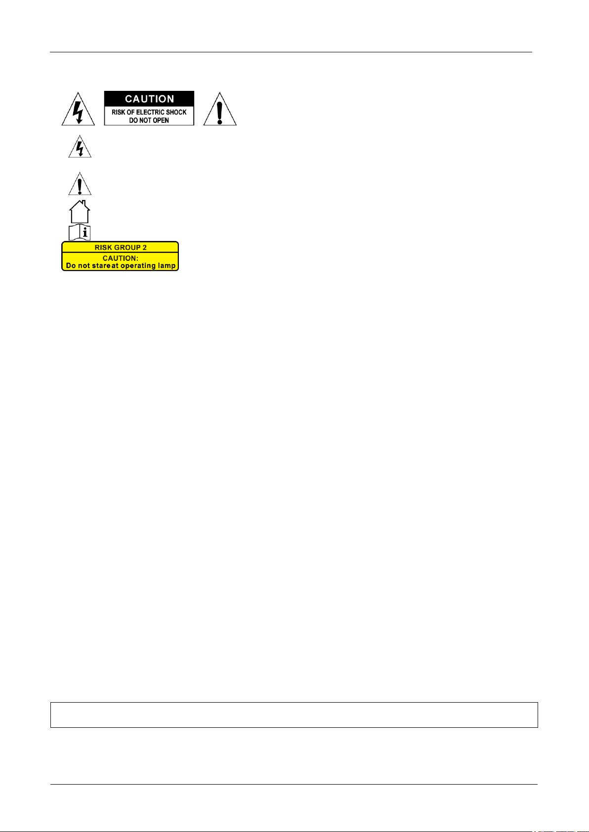
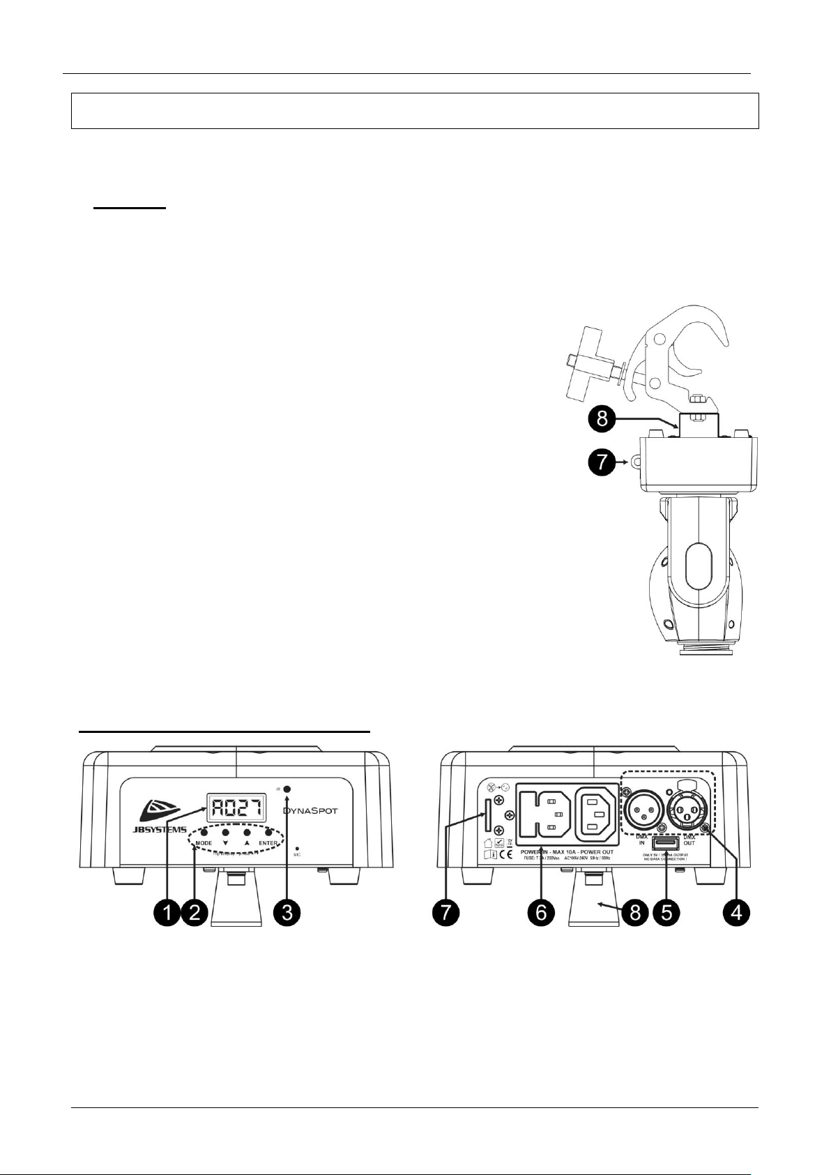
Always use a certified safety cable (number 3 on the picture) that can hold
12 times the weight of the device when installing the unit. This secondary
safety attachment should be installed in a way that no part of the
installation can drop more than 20cm if the main attachment fails.
The device should be well fixed; a free-swinging mounting is dangerous
and may not be considered!
Don’t cover any ventilation openings as this may result in overheating.
The operator has to make sure that the safety-relating and machine-
technical installations are approved by an expert before using them for the
first time. The installations should be inspected every year by a skilled
person to be sure that safety is still optimal.
HOW TO SET UP THE UNIT
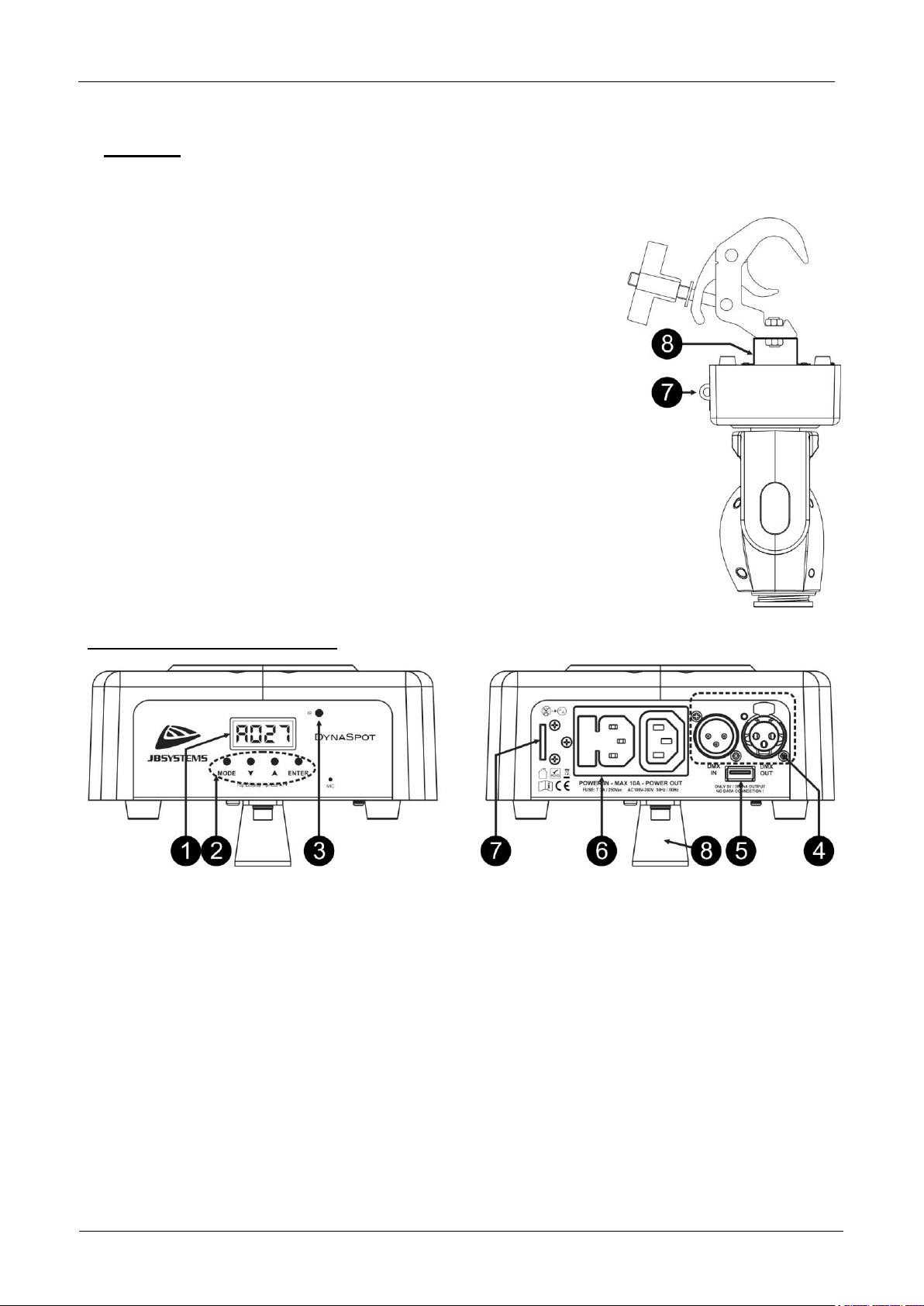
FRONT + BACK PANEL:
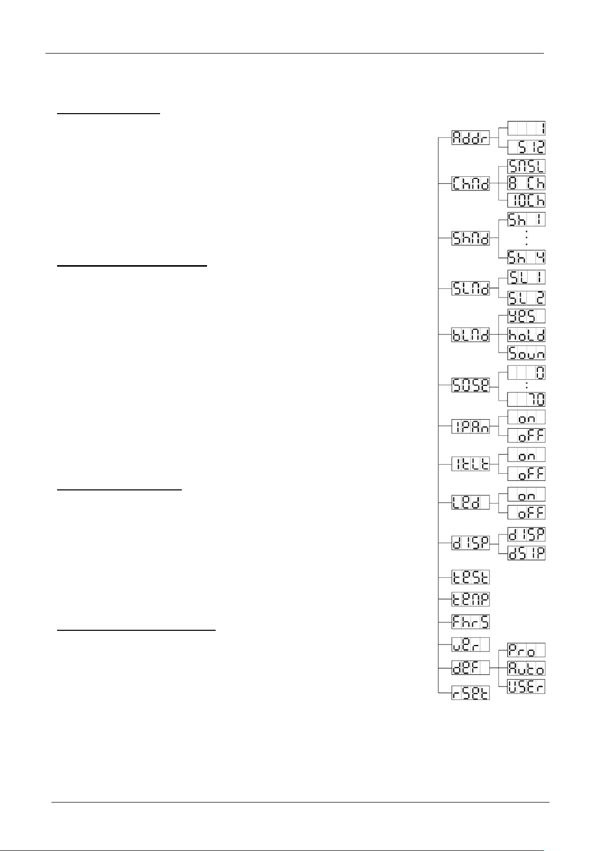
1. DISPLAY: shows the various menus and the selected functions.
2. BUTTONS:
MODE-button: used to enter and leave the setup menu.
UP/DOWN-buttons: browse the setup menu up/down and change the value of parameters.
ENTER-button: confirm your actions.
3. IR REMOTE RECEIVER: receives the infrared instructions from the IR-remote while the unit is used in
standalone or master/slave mode.
4. DMX IN/OUTPUTS: used for DMX512 linking, use balanced signal cables with 3pin XLR-connectors.
5. USB 5Vdc output: this is NOT a data connector, it’s only a 5Vdc/350mA output that can be used to
supply power to future accessories.
6. MAINS INPUT/OUTPUT: with IEC socket and integrated fuse holder, connect the supplied mains cable
here. You can use a special IEC power cable to connect the output with the mains input of the next unit
for easier linking up to 10A.
Hint: Please check our website for special cable assemblies that contain both power and balanced
signal (XLR 3pin) in one cable. Different lengths are available: 1.3m, 3m, 5m and 10m, very convenient!
7. SAFETY EYE: fix an optional safety cable here when the unit it installed above the crowd.
8. U-BRACKET: used when the projector is fixed in truss using a standard ALU-clamp.
Page 6
ENGLISH
USER MANUAL
JB SYSTEMS®
4/59
DYNASPOT
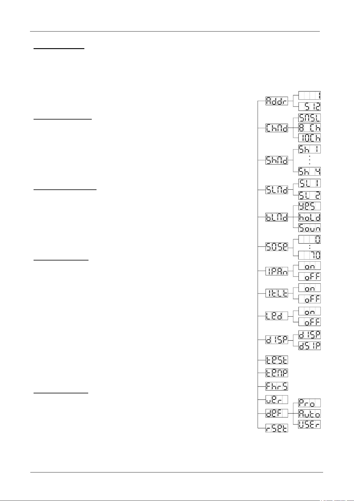
MAIN MENU:
To select any of the functions, press the MODE button and use the DOWN / UP buttons to browse the
menu.
Select the function with the ENTER button (the display blinks).
Use DOWN and UP buttons to change the mode.
Once the required mode is selected, press the ENTER button to select.
Press the MODE button for about 2 seconds to store the setting and to return to
running mode. If you don’t do this, the setting will not be stored and after about 8
seconds, the fixture will return to the previous running mode.
DMX Address [Addr]
Used to set the starting address in a DMX setup.
Press the MODE and UP/DOWN buttons until “Addr” is shown on the display.
Press the ENTER button.
Use DOWN and UP buttons to change the DMX512 address.
Once the correct address shows on the display, press the ENTER button to
select it.
Press the MODE button for about 2 seconds to store the setting and to return to
running mode.
Channel mode [ChMd]
Used to set the desired channel setup mode.
Press the MODE and UP/DOWN buttons until “ChMd” is shown on the display.
Press the ENTER button.
Use DOWN and UP buttons to choose 5MSL, 8CH or 10CH mode.
Once the desired channel setup mode shows on the display, press the ENTER
button to select it.
Press the MODE button for about 2 seconds to store the setting and to return to
running mode.
Show Mode [ShMd]
Used to choose the Show mode when used in standalone or master/slave.
Press the MODE and UP/DOWN buttons until “ShMd” is showing on the display.
Press the ENTER button.
Use DOWN and UP buttons to select one of the available shows:
Sh 1: (Show 1) Fixture is placed on the floor. Tilt movement angle 210°.
Sh 2: (Show 2) Fixture is fixed under ceiling. Tilt movement angle 90°.
Sh 3: (Show 3) Fixture is placed on a podium, in front of the audience.
The spot is always projecting to the audience’s direction; i.e. in front of the
stage. Pan movement angle (left to right to left): 160°. Tilt movement angle:
90° (60° above horizon; 30° below horizon.)
Sh 4: (Show 4) Fixture is fixed under ceiling on the stage. The spot is
mainly projecting in front of the stage. Pan movement angle (left to right to
left):160°. Tilt movement angle: 90° (vertically, front 75°; back 15°)
Once the desired mode is shown on the display, press the ENTER button to
select it.
Press the MODE button for about 2 seconds to store the setting and to return to
running mode.
Slave Mode [SLMd]
Used to make the slave unit work in opposite to the master or to work in
complete sync.
Press the MODE and UP/DOWN buttons until “SLMd” is shown on the display.
Press the ENTER button.
Use DOWN and UP button to select Slave1 (normal) or Slave2 (2 light show)
mode.
Once the right mode is shown on the display, press the ENTER button to select it.
Press the MODE button for about 2 seconds to store the setting and to return to running mode.
Page 7

ENGLISH
USER MANUAL
JB SYSTEMS®
5/59
DYNASPOT
Blackout Mode [BLMd]
Determines how the projector should react when no DMX-signal is detected.
Press the MODE and UP/DOWN buttons until “BLMd” is shown on the display.
Press the ENTER button.
Use DOWN and UP button to select one of the available blackout modes:
[YES]: The unit will go in blackout mode as soon as no DMX is detected.
[HOLd]: The unit stops moving and shows the output that corresponds to the last valid DMX-values.
[SOUn]: The unit starts working in SOUND mode, based on the settings made in the setup menu.
Once the right mode is shown on the display, press the ENTER button to select it.
Press the MODE button for about 2 seconds to store the setting and to return to running mode.
Sound Sense [SOSE]
Used to set the sensitivity of the internal microphone
Press the MODE and UP/DOWN buttons until “SOSE” is shown on the display.
Press the ENTER button.
Use DOWN and UP button to choose a value between “00” (very low sensitivity) and “70” (high sensitivity).
Once the right value is shown on the display, press the ENTER button select it.
Press the MODE button for about 2 seconds to store the setting and to return to running mode.
Pan Inversion [IPAn]
Normal: Panning movement is not inversed.
Pan inversion: Panning movement is inversed
Press the MODE and UP/DOWN buttons until “IPAn” is shown on the display.
Press the ENTER button.
Use DOWN and UP button to select “OFF” (normal) or “On” (pan inversion) mode.
Once the mode is selected, press the ENTER button to select it.
Press the MODE button for about 2 seconds to store the setting and to return to running mode.
Tilt Inversion [ItLt]
Normal: Tilt movement is not inversed.
Tilt inversion: tilt movement is inversed
Press the MODE and UP/DOWN buttons until “ItLt” is shown on the display.
Press the ENTER button.
Use DOWN and UP button to choose “OFF” (normal) or “On” (tilt inversion) mode.
Once the right mode is shown on the display, press the ENTER button to select it.
Press the MODE button for about 2 seconds to store the setting and to return to running mode.
Led Display on/off [Led]
Switches the LED display automatically off or not.
Press the MODE and UP/DOWN buttons until “Led” is shown on the display.
Press the ENTER button.
Use DOWN and UP buttons to select “On” (display always lit) or “Off” (display dark when not used).
Once the right mode is shown on the display, press the ENTER button to select it.
Press the MODE button for about 2 seconds to store the setting and to return to running mode.
Display Rotation [dISP]
Rotate the display over 180° (upside-down) or not.
Press the MODE and UP/DOWN buttons until the display shows “dISP”.
Press the ENTER button.
Use DOWN and UP buttons to select “dISP” (normal display always lit) or “dSIP” (display upside-down).
Once the right position is shown on the display, press the ENTER button to select it.
Press the MODE button for about 2 seconds to store the setting and to return to running mode.
Auto Test [tESt]
Used to activate the internal “self-test” program which checks all possibilities of the unit.
Press the MODE and UP/DOWN buttons until the display shows “tESt”.
Press the ENTER button to start the internal self-test program.
To go back to the functions press the MODE button for about 2 seconds.
Page 8
ENGLISH
USER MANUAL
JB SYSTEMS®
6/59
DYNASPOT
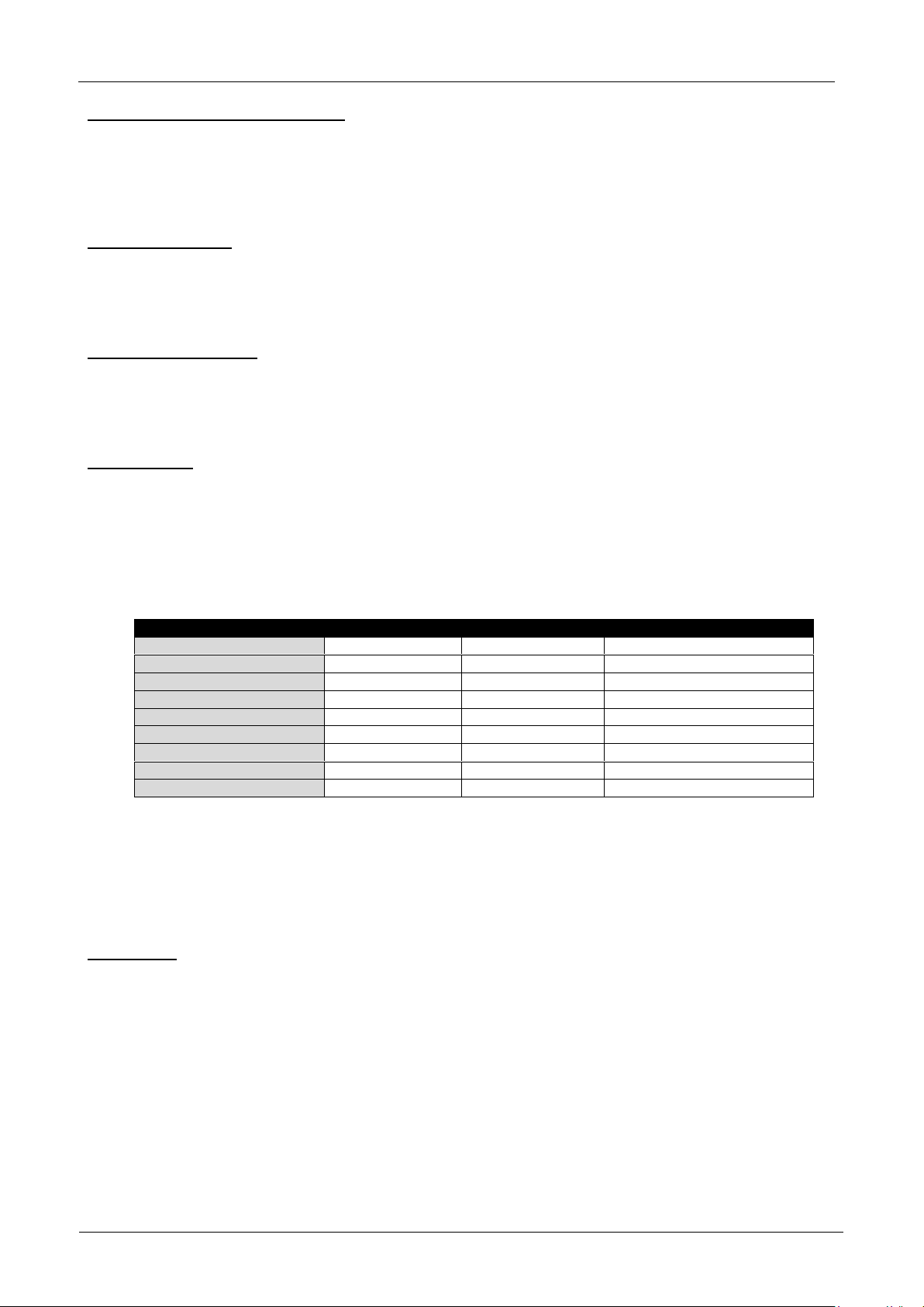
PARAMETER name
PRO defaults
AUTO defaults
USER defaults
ChMd – DMX Channel mode
10 ch
5 MSL
Personal user setting
ShMd – Show mode
Sh 1
Sh 1
Personal user setting
SLMd – Slave mode
SL 1
SL 1
Personal user setting
bLMd – Blackout mode
Hold
Soun
Personal user setting
SoSE – Sound sensitivity
60
60
Personal user setting
IPAN – PAN inversion
oFF
oFF
Personal user setting
ItLt – TILT inversion
oFF
oFF
Personal user setting
Led – Display on/off
oFF
on
Personal user setting
DISP – Display upside down
oFF
oFF
Personal user setting
Temperature inside the unit [tEMP]
Used to show the temperature inside the unit
Press the MODE and UP/DOWN buttons until the display shows “tEMP”.
Press the ENTER button to show the internal LED temperature of the unit on the display.
To go back to the functions press the MODE button again.
If you want to go back to normal running mode: press the MODE button for about 2 seconds.
Fixture Time [FHrS]
Used to show the number of working hours of the unit.
Press the MODE and UP/DOWN buttons until the display shows “FHrS”.
Press the ENTER button to show the number of working hours in the display.
To go back to the functions press the MODE button.
Firmware version [VEr]
Used to show the software version that is installed in the unit
Press the MODE and UP/DOWN buttons until the display shows “VEr”.
Press the ENTER button to show the software version on the display.
To go back to the functions press the MODE button.
Defaults [dEF]
Used to choose between 3 sets of default parameter settings.
Press the MODE and UP/DOWN buttons until the display shows “dEF”.
Press the ENTER button:
Use DOWN and UP buttons to select one of the options:
PRO-defaults [PrO] : loading basic settings for use on DMX-controllers.
AUTO-defaults [AUtO] : loading basic settings for easy master/slave use.
USER-defaults [USEr] : saving or loading your own preferred settings.
Press the ENTER: the display shows “LOAd” (or “StOr” *). To avoid accidental loss of your settings you
have to confirm the action: use DOWN and UP buttons to select “Yes” or “No” and confirm by pressing the
ENTER button.
Press the MODE button for about 2 seconds to store the setting and to return to running mode.
REMARK (*): When “USER-defaults” is selected you can also choose to store the current settings of the
setup menu: use the UP/DOWN buttons to choose [StOr] “store” on the display.
Reset [rESt]
Used to force a reset of the unit.
Press the MODE and UP/DOWN buttons until the display shows “rESt”.
Press the ENTER button to reset the unit.
REMARK: also check the chapter about the DMX-channel configuration of the unit to find out how you can
force a reset by DMX.
Page 9

ENGLISH
USER MANUAL
JB SYSTEMS®
7/59
DYNASPOT
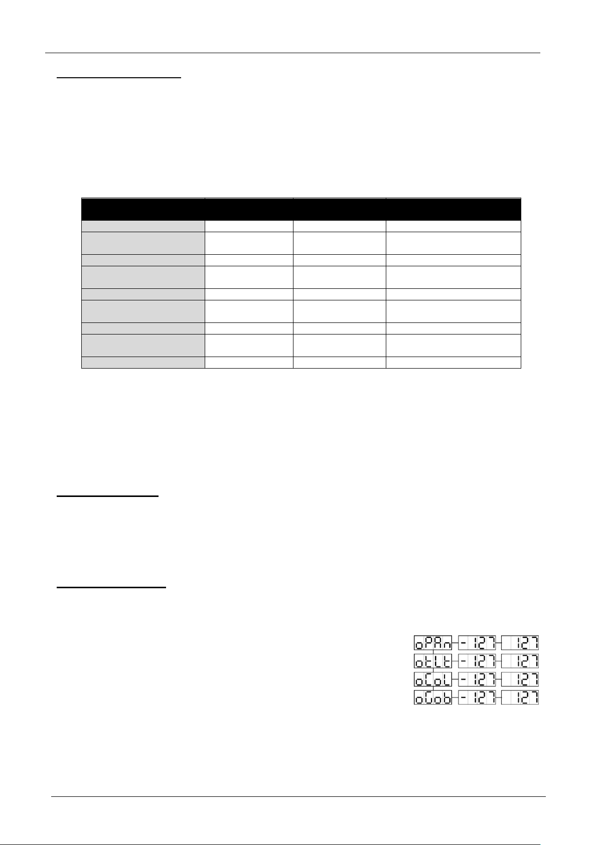
OFFSET MENU:
Used to adjust the home position of several functions: offset parameters for PAN, TILT, COLORS and
GOBOS.
Make sure that the unit is connected to a DMX-controller and set to 10CH channel mode: set ch6 + ch7 to
maximum.
If you’re not already in the setup menu, just press the MODE button shortly to
enter the setup menu.
Now press the ENTER button for at least 5 seconds to go into offset mode.
Use DOWN and UP buttons to select the function that you want to adjust
Press the ENTER button.
Use DOWN and UP buttons to adjust the home position
Press the ENTER button to select your setting.
Press the MODE button for about 2 seconds to store the setting and to return to running mode.
ELECTRICAL INSTALLATION + ADDRESSING
Important: The electrical installation should be carried out by qualified personal only,
Electrical installation for 1 standalone unit:
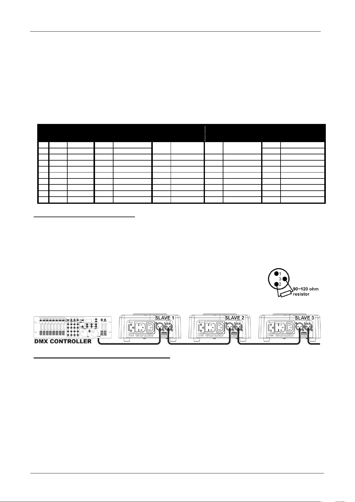
Electrical installation for two or more units in master/slave:
In this mode the units will show a synchronized show, working to the rhythm of the beat.
according to the regulations for electrical and mechanical safety in your country.
Just insert the mains cable. The unit starts working immediately in stand-alone mode.
Remark1: You can use the included infrared remote controller if you want to have more control. Refer to
“OPERATE THE UNIT BY INFRARED REMOTE” to learn how to do this.
Remark2: if there’s no output, please make sure to set the blackout mode [BLMd] of the projector to
“SOUN” and sound sensitivity [SOSE] to a value over 50 (see previous chapter).
Connect 2 to maximum 16 units together using good quality balanced microphone cables. The first unit
in the chain will automatically act as the master, the other units will act automatically as slaves.
Make sure that all units are connected to the mains.
Done!
Remark1: You can use the included infrared remote controller if you want to have more control. Refer to
“OPERATE THE UNIT BY INFRARED REMOTE” to learn how to do this.
Remark2: if there’s no output, please make sure to set the blackout mode [BLMd] of the MASTER
projector to “SOUN” and sound sensitivity [SOSE] to a value over 50 (see previous chapter).
Electrical installation for two or more units in DMX-master/slave:
In this mode the units will show a synchronized show, working to the rhythm of the beat but you can still
control some functions on the master by 1 or 5 DMX-channels.
To assure proper operation you need an optional “Mini DMX-SPLITTER” to isolate the master/slave line
from the main DMX-line, see drawing.
Connect 2 to maximum 16 units together using good quality balanced microphone cables. The first unit
in the chain will act as the master, the other units will act automatically as slaves.
Page 10
ENGLISH
USER MANUAL
JB SYSTEMS®
8/59
DYNASPOT
1 – DIM
2 - STROBE
3 - COLOR
4 - GOBO
5 - PAN/TILT SPEED
VALUE
FUNCTION
VALUE
FUNCTION
VALUE
FUNCTION
VALUE
FUNCTION
VALUE
FUNCTION
10
255
100%
255
FAST STROBE
218-255
ORIGINAL
COLORS
218-255
ORIGINAL GOBOS
255
AUDIO FAST
9
8
188-217
COLOR 7
188-217
GOBO 7
7
158-187
COLOR 6
158-187
GOBO 6
RANDOM
6
128-157
COLOR 5
128-157
GOBO 5
PROGRAM
5
098-127
COLOR 4
098-127
GOBO 4
AUDIO TRIGGERED
4
068
SLOW STROBE
068-097
COLOR 3
068-097
GOBO 3
3
038-067
SOUND STROBE
038-067
COLOR 2
038-067
GOBO 2
2
008
0%
008-037
RANDOM STROBE
008-037
COLOR 1
008-037
GOBO 1
008
AUDIO VERY SLOW
1
000-007
STANDBY
000-007
OPEN
000-007
WHITE
000-007
NO GOBO
000-007
HOLD (FREEZE)
Set the master to 5MSL channel mode (see previous chapter). Check the DMX-chart below to see the
difference between both channel modes.
For the DMX-controller the master and his slaves can now be considered as 1 virtual effect that needs a
start address so it can be controlled as any other DMX-unit in the DMX chain: see “DMX Address” in the
chapter “Main Menu” to see how you can set the DMX-start address.
Make sure that all units are connected to the mains.
Set the DMX-controller according to the DMX-chart below.
Done!
Remark: in order to work well to the rhythm of the music, make sure to set the blackout mode [BLMd] of
the MASTER projector to “SOUN” and sound sensitivity [SOSE] to a value over 50 (see previous chapter).
DMX-Chart for 5MSL working modes
Electrical installation in DMX-mode:
The DMX-protocol is a widely used high speed signal to control intelligent light equipment. You need to
“daisy chain” your DMX controller and all the connected units with a good quality balanced cable.
Both XLR-3pin and XLR-5pin connectors are used, however XLR-3pin is more popular because these
cables are compatible with balanced audio cables.
Pin layout XLR-3pin:
Pin layout XLR-5pin:
To prevent strange behavior of the light effects, due to interferences, you must use a 90Ω to 120Ω
terminator at the end of the chain. Never use Y-splitter cables, this simply won’t
work!
Make sure that all units are connected to the mains.
Each light effect in the chain needs to have its proper starting address so it knows
which commands from the controller it has to decode. In the next section you will
learn how to set the DMX addresses.
Pin1 = GND ~ Pin2 = Negative signal (-) ~ Pin3 = Positive signal (+)
Pin1 = GND ~ Pin2 = Negative signal (-) ~ Pin3 = Positive signal (+) ~ Pins4+5 not used.
HOW TO SET THE RIGHT STARTING ADDRESS:
Refer to the previous chapter (DMX-512 address setting) to learn how to set the starting address on this unit.
The starting address of each unit is very important. Unfortunately it is impossible to tell you in this user
manual which starting addresses you have to set because this completely depends on the controller you will
use… So please refer to the user manual of your DMX-controller to find out which starting addresses you
must set.
Page 11

ENGLISH
USER MANUAL
JB SYSTEMS®
9/59
DYNASPOT
8CH
10CH
VALUE
FUNCTION
1
1
000 - 255
Pan
2
000 - 255
Pan Fine (Least significant bit)
2
3
000 - 255
Tilt
4
000 - 255
Tilt Fine (Least significant bit)
3
5
000 - 255
Pan / Tilt Speed (000 = fast ~ 255 = slow)
4
6
000 - 255
Dimmer (0 to 100%)
5
7
Strobe / Shutter effect
000 - 007
Shutter closed (no output)
008 - 015
Shutter open
016 - 131
Strobe 1 (slow → fast)
132 - 139
Shutter open
140 - 181
Strobe 2: slow open / instant close (slow → fast)
182 - 189
Shutter open
190 - 231
Strobe 3: instant open / slow close (slow → fast)
232 - 239
Shutter open
240 - 247
Strobe 4: random strobe
248 - 255
Shutter open
6 8
Color wheel
000 - 014
COLOR 1: White (open)
015 - 028
COLOR 2: Red
029 - 042
COLOR 3: Orange
043 - 056
COLOR 4: Yellow
057 - 070
COLOR 5: Green
071 - 084
COLOR 6: Blue
085 - 098
COLOR 7: Magenta
099 - 112
COLOR 8: Light Blue
113 - 255
Color wheel turning (slow → fast)
7
9
Gobo wheel
000 - 014
OPEN (no gobo)
015 - 028
GOBO 1
029 - 042
GOBO 2
043 - 056
GOBO 3
057 - 070
GOBO 4
071 - 084
GOBO 5
085 - 098
GOBO 6
099 - 255
Gobo wheel turning (slow → fast)
8
10
Special functions
000 - 007
Normal DMX-mode
008 - 010
Reset all (after 5sec)
011 - 247
Not used
248 - 255
RANDOM PROGRAM (audio triggered)
DMX-CONFIGURATION OF THE DYNASPOT IN 8 AND 10CH MODE:
Page 12
ENGLISH
USER MANUAL
JB SYSTEMS®
10/59
DYNASPOT
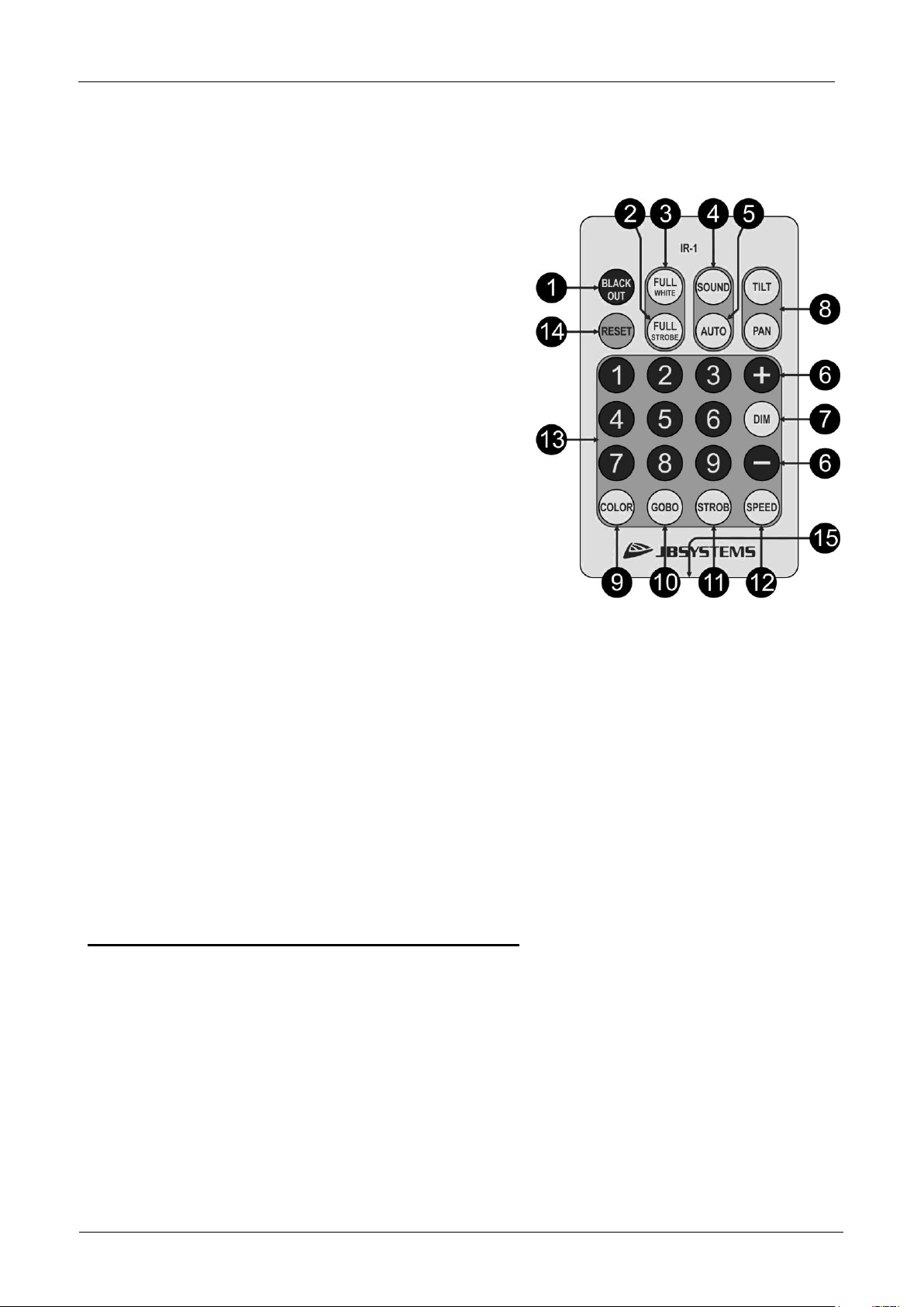
OPERATE THE UNIT BY INFRARED REMOTE
When used in standalone or master/slave mode we strongly advise you to use the included infrared remote
control. For proper operation make sure to point the remote to the front panel of the master unit. Now you
can control all the connected units:
1. [BLACKOUT] button: used to switch the output ON/OFF.
2. [FULL STROBE] button: press to select fast strobe in
white color and full output, no gobo selected. Press again
to return to normal.
3. [FULL WHITE] button: press to select white color at full
output and no gobo selected. Press again to return to
normal.
4. [SOUND] button: Press to trigger the PAN/TILT
movements to the beats of the music.
5. [AUTO] button: Press to trigger the PAN/TILT movements
automatically. You can adjust the speed by pressing the
[+/–] buttons (6).
6. + / - buttons: used to increase / decrease the value of
certain functions.
7. [DIM] button: press the [DIM] button followed by one of
the 9 number buttons (13) to select one of the preset
dimmer levels (10% steps) or press the [DIM] button
followed by the [+/-] buttons (6) to set the output exactly as
you want.
8. [TILT / PAN] buttons: press the [TILT] or [PAN] button,
followed by the [+/-] buttons to point the beams in a certain
direction. Just press the [SOUND] or [AUTO] buttons to
return back to normal pan/tilt movements.
9. [COLOR] button: press the [COLOR] button followed by one of the 9 number buttons (13) to select one
of the colors. Number button “9” will scroll the different colors automatically at medium speed.
10. [GOBO] button: press the [GOBO] button followed by one of the 9 number buttons (13) to select one of
the gobos. Number buttons “8” & “9” will scroll the different gobo automatically at slow or medium speed.
11. [STROB] button: press the [STROB] button followed by one of the 9 number buttons (13) to select the
desired strobe function: “1”= no strobe, “2” = random strobe, “3” to “9” = strobe with increasing speed.
12. [SPEED] button: press the [SPEED] button followed by one of the 9 number buttons (13) to select the
desired PAN/TILT speed: “1”= complete stop, “2” to “9” = pan/tilt movements with increasing speed.
13. [1…9] number buttons: used to select preset values for the different functions.
14. [RESET] button: this button allows you to reset the projectors from a distance. When you press this
button shortly nothing happens, when you press this button for more than 3 seconds the units start
resetting. (only to be used when something is wrong and a reset seems needed)
MAINTENANCE
Make sure the area below the installation place is free from unwanted persons during servicing.
Switch off the unit, unplug the mains cable and wait until the unit is cooled down.
During inspection the following points should be checked:
All screws used for installing the device and any of its parts should be tightly fastened and may not be
corroded.
Housings, fixations and installations spots (ceiling, truss, suspensions) should be totally free from any
deformation.
When an optical lens is visibly damaged due to cracks or deep scratches, it must be replaced.
The mains cables must be in impeccable condition and should be replaced immediately when even a
small problem is detected.
In order to protect the device from overheat the cooling fans (if any) and ventilation openings should be
cleaned monthly.
The interior of the device should be cleaned annually using a vacuum cleaner or air-jet.
The cleaning of internal and external optical lenses and/or mirrors must be carried out periodically to
optimize light output. Cleaning frequency depends on the environment in which the fixture operates: damp,
smoky or particularly dirty surroundings can cause greater accumulation of dirt on the unit’s optics.
Clean with a soft cloth using normal glass cleaning products.
Page 13
ENGLISH
USER MANUAL
JB SYSTEMS®
11/59
DYNASPOT
Always dry the parts carefully.
Clean the external optics at least once every 30 days.
Clean the internal optics at least every 90 days.
Attention: We strongly recommend internal cleaning to be carried out by qualified personnel!
SPECIFICATIONS
This unit is radio-interference suppressed. This product meets the requirements of the current European and
national guidelines. Conformity has been established and the relevant statements and documents have been
deposited by the manufacturer.
Mains Input: AC 100 - 240V, 50/60Hz
Power consumption: 37 Watt (max)
Fuse: 250V 3A slow blow (20mm glass)
Power connections: IEC - 10A Power linking capacity.
DMX connections: Neutrik 3pin-XLR male / female
DMX channels used: 8ch + 10ch + 5MSL
Lamp: 10W LED Engine
Beam Angle: 12°
Color wheel: 8 colors + open
GOBO wheel: 7 fixed gobos
IP-Rating: IP20
Operating temperature (Ta): 0°C to 40°C
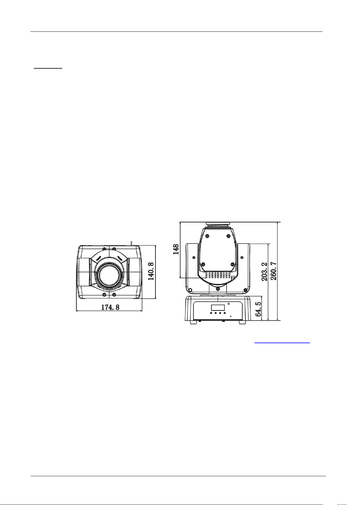
Size: 170 x 170 x 200 mm (LxBxH)
Weight: 2,8 kg
You can download the latest version of this user manual on our website: www.jb-systems.eu
Every information is subject to change without prior notice
Page 14

FRANÇAIS
GUIDE D’UTILISATION
JB SYSTEMS®
12/59
DYNASPOT
GUIDE D’UTILISATION
Nous vous remercions d’avoir acheté ce produit JB Systems
possibilités du produit et pour votre propre sécurité, lisez ces instructions très attentivement avant d’utiliser
cet appareil.
CARACTÉRISTIQUES
Une lyre spot à LED extrêmement compacte mais très lumineuse avec un faisceau de 12°
Spécialement conçue pour les DJ et les petits clubs.
Basé sur la plus récente LED 10 W de la marque CREE
Très faible consommation électrique, seulement 37 W (économie d’argent !)
Divers effets stroboscopiques et gradation de 0 à 100 %
1 roue de gobo séparée avec 6 gobos fixes + ouvert
1 roue chromatique séparée de 8 couleurs
Excellents programmes intégrés offrant de fabuleux shows de lumière en perpétuels changements.
Télécommande infrarouge fournie pour mode autonome et maître/esclave, pas besoin de contrôleur DMX.
De nombreux modes de fonctionnement :
Contrôle DMX : via 5, 8 ou 10 canaux
Autonome : activé par le son via son micro interne
Maître/esclave : des shows de lumière merveilleux et synchronisés en mode autonome
Maître/esclave DMX : plusieurs unités fonctionnent éventuellement en maître/esclave en mode audio
synchronisé, alors que l’utilisateur n’a besoin que de 5 canaux DMX pour maintenir le contrôle des
couleurs, des gobos, du stroboscope, de la vitesse de panoramique/inclinaison et de gradation.
Trois réglages par défaut différents, facile pour les entreprises de location :
Réglages par défaut PRO : réglages de base pour les modes contrôleurs DMX.
Réglages par défaut AUTO : réglages de base pour faciliter l’utilisation des modes maître/esclave.
Réglages par défaut UTILISATEUR : mémoriser et rappeler vos réglages préférés !
Mises à jour du logiciel via une unité spéciale
Entrée/sorties secteur CEI : mise en série simple de plusieurs unités, jusqu’à 10 A.
Sortie 5V/350 mA (prise USB)
Afficheur LED sur 4 caractères pour une navigation par menu simple
®
. Pour tirer pleinement profit de toutes les
AVANT UTILISATION
Avant d’utiliser cet appareil, vérifiez s’il n’a pas été endommagé durant le transport. En cas de dommages,
n’utilisez pas l’appareil et consultez immédiatement votre revendeur.
Important : Cet appareil est expédié de notre usine en parfait état et bien emballé. Il est absolument
nécessaire que l’utilisateur suive strictement les instructions et les avertissements de sécurité se trouvant
dans ce manuel. Tout dommage dû à une mauvaise manipulation n’est pas garanti. Le revendeur
n’accepte aucune responsabilité pour tous les défauts et problèmes dus au non-respect de ce manuel.
Conservez ce manuel dans un endroit sûr pour toute consultation future. Si vous vendez l’appareil,
assurez-vous de joindre ce manuel.
Vérifiez le contenu :
Vérifiez que le carton contient les éléments suivants :
Lyre DYNASPOT
Support en U avec boulons (pour collier d’ancrage)
Câble d’alimentation CEI
Instructions d’utilisation
Page 15
FRANÇAIS
GUIDE D’UTILISATION
JB SYSTEMS®
13/59
DYNASPOT
ATTENTION : Pour réduire le risque de choc électrique, ne
retirez pas le panneau supérieur. L’appareil ne contient aucun
composant réparable par l’utilisateur. Confiez toute réparation à
un personnel qualifié uniquement.
Le symbole de l’éclair à l’intérieur d’un triangle équilatéral est destiné à alerter l’utilisateur de la
présence de « tensions dangereuses » non isolées à l’intérieur de l’appareil, d’une magnitude
pouvant constituer un risque d’électrocution.
Le symbole du point d’exclamation dans un triangle équilatéral sert à avertir l’utilisateur que
d’importants conseils d’utilisation et de maintenance sont fournis dans la documentation
accompagnant l’appareil.
Ce symbole signifie : pour un usage intérieur uniquement
Ce symbole signifie : lisez les instructions
ATTENTION : Ne fixez pas votre regard sur une lampe allumée.
Peut être nocif pour les yeux.
INSTRUCTIONS DE SÉCURITÉ :
Pour protéger l’environnement, essayez de recycler autant que possible les matériaux d’emballage.
Pour éviter tout incendie ou électrocution, n’exposez pas cet appareil à la pluie ou à l’humidité.
Pour éviter une formation de condensation interne, laissez l’appareil s’adapter à la température ambiante
quand vous le mettez dans une pièce chaude après le transport. La condensation empêche parfois
l’appareil de fonctionner à plein rendement ou peut même causer des dommages.
Cet appareil est destiné à un usage intérieur seulement.
Ne placez pas d’objets métalliques et ne renversez pas de liquides à l’intérieur de l’appareil. Un choc
électrique ou un dysfonctionnement peut en résulter. Si un corps étranger pénètre dans l’appareil,
débranchez immédiatement le cordon d’alimentation de la prise secteur.
Placez l’appareil dans un endroit bien aéré, loin de tout matériau et/ou liquide inflammable. L’appareil doit
être fixé à au moins 50 cm des murs environnants.
Ne couvrez pas les ouvertures de ventilation, cela pourrait entraîner une surchauffe.
Évitez une utilisation dans des environnements poussiéreux et nettoyez l’appareil régulièrement.
Gardez l’appareil loin de la portée des enfants.
Les personnes inexpérimentées ne doivent pas utiliser cet appareil.
La température ambiante de fonctionnement maximale est de 40 °C. N’utilisez pas cet appareil à des
températures ambiantes plus élevées.
Assurez-vous qu’aucune personne étrangère ne se trouve dans la zone en dessous de l’emplacement
d’installation durant le montage, le démontage et l’entretien.
Laissez environ 10 minutes à l’appareil pour refroidir avant de commencer l’entretien.
Débranchez toujours l’appareil lorsqu’il ne va pas être utilisé pendant une longue période ou avant de
commencer l’entretien.
L’installation électrique doit être effectuée par du personnel qualifié, conformément à la réglementation en
matière de sécurité électrique et mécanique dans votre pays.
Vérifiez que la tension secteur n’est pas supérieure à celle indiquée sur l’appareil.
Le cordon d’alimentation doit toujours être en parfait état. Éteignez immédiatement l’appareil dès que le
cordon d’alimentation est écrasé ou endommagé. Il doit être remplacé par le fabricant, son agent de
service ou une personne de même qualification afin d’éviter tout danger.
Ne laissez jamais le cordon d’alimentation entrer en contact avec d’autres câbles !
Ce luminaire doit être mis à la terre pour être conforme à la réglementation en matière de sécurité.
Ne connectez pas l’appareil à un variateur de lumière.
Utilisez toujours un câble de sécurité approprié et certifié lors de l’installation de l’appareil.
Afin d’éviter un choc électrique, n’ouvrez aucun panneau. L’appareil ne contient aucun composant
réparable par l’utilisateur.
Ne réparez jamais un fusible et ne court-circuitez jamais le porte-fusible. Remplacez toujours un fusible
endommagé par un fusible du même type ayant les mêmes spécifications électriques !
En cas de sérieux problèmes de fonctionnement, cessez d’utiliser l’appareil et contactez immédiatement
votre revendeur.
Le boîtier et les lentilles optiques doivent être remplacés s’ils sont visiblement endommagés.
Utilisez l’emballage d’origine pour transporter l’appareil.
Pour des raisons de sécurité, il est interdit d’apporter des modifications non autorisées à l’appareil.
Page 16
FRANÇAIS
GUIDE D’UTILISATION
JB SYSTEMS®
14/59
DYNASPOT
Important : Ne regardez jamais directement la source de lumière ! N’utilisez pas le jeu de lumière en
présence de personnes souffrant d’épilepsie.
SUSPENDRE L’APPAREIL
Important : L’installation ne doit être effectuée que par un personnel qualifié. Une mauvaise
installation peut entraîner des blessures et/ou dommages graves. La suspension de l’appareil
exige une grande expérience ! Les limites de charge de fonctionnement doivent être respectées,
des matériels d’installation certifiés doivent être utilisés, l’appareil installé doit être inspecté
régulièrement pour vérifier les conditions de sécurité.
Assurez-vous qu’aucune personne étrangère ne se trouve dans la zone en dessous de l’emplacement
d’installation durant le montage, le démontage et l’entretien.
Fixez l’appareil dans un endroit bien aéré, loin de tout matériau et/ou
liquide inflammable. L’appareil doit être fixé à au moins 50 cm des murs
environnants.
L’appareil doit être installé hors de portée des personnes, loin des
passages et des endroits où des personnes peuvent aller et venir, ou
s’asseoir.
Avant de lever l’appareil, assurez-vous que le point de suspension peut
supporter une charge d’au moins 10 fois le poids de l’appareil.
Lors de l’installation, utilisez toujours un câble (Numéro 3 sur l’image) de
sécurité certifié qui peut supporter 12 fois le poids de l’appareil. Ce
support de suspension de sécurité secondaire doit être installé de manière
à ce qu’aucune partie de l’installation ne puisse tomber de plus de 20 cm
si le support principal lâche.
L’appareil doit être bien fixé, un montage balançant est dangereux et ne
doit pas être envisagé !
Ne couvrez pas les ouvertures de ventilation, cela pourrait entraîner une
surchauffe.
L’opérateur doit s’assurer que la sécurité relative à l’installation et les
conditions techniques sont approuvées par un expert avant d’utiliser
l’appareil pour la première fois. Les installations doivent être inspectées
chaque année par une personne qualifiée pour être sûr que la sécurité est
toujours optimale.
CONFIGURATION DE L’UNITÉ
PANNEAU AVANT + ARRIÈRE :
1. AFFICHEUR : affiche les différents menus et les fonctions sélectionnées.
2. TOUCHES :
Touche [MODE] : pour accéder et quitter le menu configuration.
Touches / : pour parcourir vers le haut/bas le menu configuration et modifier la valeur d’un
paramètre.
Touche [ ENTER] : pour confirmer vos opérations.
3. RÉCEPTEUR IR DE LA TÉLÉCOMMANDE : reçoit les commandes infrarouges de la télécommande IR
quand l’unité est utilisée en mode autonome ou maître/esclave.
Page 17

FRANÇAIS
GUIDE D’UTILISATION
JB SYSTEMS®
15/59
DYNASPOT
4. ENTRÉES/SORTIES DMX : utilisé pour la connexion DMX512. Utilisez des câbles de signaux
symétriques avec des connecteurs XLR 3 broches.
5. Sortie USB 5 V cc : ce n’est PAS un connecteur de données, il fournit uniquement l’alimentation de
sortie 5 V cc/350 mA pour de futurs accessoires.
6. ENTRÉE/SORTIE SECTEUR : connectez le câble d’alimentation secteur à ce connecteur CEI avec
porte-fusible. Un câble d’alimentation spéciale CEI peut être connecté de cette sortie à l’entrée secteur
d’une autre unité pour simplifier la mise en série jusqu’à 10 A.
Astuce : Veuillez consulter notre site Web pour le jeu de câble spécial qui achemine l’alimentation et le
signal symétrique (XLR) sur un seul câble. Différentes longueurs sont disponibles : 1,3 m, 3 m, 5 m et
10 m, très pratiques !
7. ŒILLETON DE SÉCURITÉ : fixez ici un câble de sécurité supplémentaire quand l’unité est installée au-
dessus des spectateurs.
8. SUPPORT EN U : utilisé quand le projecteur est fixé dans les fermes à l’aide d’un collier ALU standard.
MENU PRINCIPAL :
Pour sélectionner une fonction quelconque, appuyez sur la touche [MODE] et utilisez les touches /
pour parcourir le menu.
Sélectionnez une fonction avec la touche [ENTER] (l’affichage se met à clignoter).
Utilisez les touches et pour changer de mode.
Une fois que le mode désiré est sélectionné, appuyez sur la touche [ENTER] pour valider.
Appuyez sur la touche [MODE] pendant environ 2 secondes pour mémoriser les réglages et revenir en
mode de fonctionnement normale. Si vous ne le faites pas, le réglage ne sera pas mémorisé et au bout de
8 secondes, l’appareil revient au mode de fonctionnement précédent.
Adresse DMX [Addr]
Utilisée pour définir l’adresse de départ dans une configuration DMX.
Appuyez sur les touches [MODE] et / jusqu’à ce que la mention « Addr » apparaisse sur l’afficheur.
Appuyez sur la touche [ENTER].
Utilisez les touches et pour modifier l’adresse DMX512.
Une fois que l’adresse souhaitée apparaît sur l’afficheur, appuyez sur la touche [ENTER] pour la
sélectionner.
Appuyez sur la touche [MODE] pendant environ 2 secondes pour mémoriser les réglages et revenir en
mode de fonctionnement normale.
Mode canal [ChMd]
Utilisé pour définir le mode configuration de canal.
Appuyez sur les touches [MODE] et / jusqu’à ce que la mention « ChMd » apparaisse sur l’afficheur.
Appuyez sur la touche [ENTER].
Utilisez les touches et pour choisir le mode 5MSL, 8CH ou 10CH.
Une fois que le mode de configuration du canal souhaité apparaît sur l’afficheur, appuyez sur la touche
[ENTER] pour le sélectionner.
Appuyez sur la touche [MODE] pendant environ 2 secondes pour mémoriser les réglages et revenir en
mode de fonctionnement normale.
Mode des jeux de lumière [ShMd]
Utilisé pour choisi le mode des jeux de lumière en mode autonome ou maître/esclave. Appuyez sur les
touches [MODE] et / jusqu’à ce que la mention « ShMd » apparaisse sur l’afficheur.
Appuyez sur la touche [ENTER].
Utilisez les touches et pour sélectionner l’un des jeux de lumière disponibles :
Sh 1 : l’appareil (show 1) est placé sur le sol. L’angle d’inclinaison est de 210°.
Sh 2 : l’appareil (show 2) est fixé au plafond. L’angle d'inclinaison est de 90°.
Sh 3 : l’appareil (show 3) est placé sur la scène, devant le public. Le projecteur est toujours orienté
vers le public, c’est à dire ceux devant la scène. Angle de mouvement panoramique (gauche-droitegauche) : 160°. Angle de mouvement d’inclinaison : 90° (60° au-dessus de l’horizontale ; 30° sous
l’horizontale.)
Sh 4 : l’appareil (show 4) est fixé au plafond sur la scène. Le projecteur est principalement dirigé
vers l’avant de la scène. Angle de mouvement panoramique (gauche-droite-gauche) : 160°. Angle de
mouvement d’inclinaison : 90° (verticalement, 75° vers l’avant, 15° vers l’arrière)
Une fois le mode souhaité sur l’afficheur, appuyez sur la touche [ENTER] pour le sélectionner.
Page 18
FRANÇAIS
GUIDE D’UTILISATION
JB SYSTEMS®
16/59
DYNASPOT
Appuyez sur la touche [MODE] pendant environ 2 secondes pour mémoriser les réglages et revenir en
mode de fonctionnement normale.
Mode esclave [SLMd]
Utilisé pour faire fonctionner l’appareil esclave en opposition au maître ou en
synchronisation totale.
Appuyez sur les touches [MODE] et / jusqu’à ce que la mention « SLMd »
apparaisse sur l’afficheur.
Appuyez sur la touche [ENTER].
Utilisez les touches / pour sélectionner le mode Slave1 (normal) ou Slave2
(2 jeux de lumière).
Une fois que le bon mode apparaît sur l’afficheur, appuyez sur la touche
[ENTER] pour le sélectionner.
Appuyez sur la touche [MODE] pendant environ 2 secondes pour mémoriser les
réglages et revenir en mode de fonctionnement normale.
Mode obscurcissement [BLMd]
Détermine le comportement du projecteur quand aucun signal DMX n’est
détecté.
Appuyez sur les touches [MODE] et / jusqu’à ce que la mention « BLMd »
apparaisse sur l’afficheur.
Appuyez sur la touche [ENTER].
Utilisez les touches et pour sélectionner l’un des modes d’obscurcissement
disponibles :
[YES] : l’unité passe en mode obscurcissement dès qu’aucun signal DMX
n’est détecté.
[HOLd] : l’unité se fige et affiche la sortie qui correspond à la dernière valeur
DMX valide.
[SOUn] : l’unité se met à fonctionner en mode SONORE en fonction des
réglages effectués dans le menu.
Une fois que le bon mode apparaît sur l’afficheur, appuyez sur la touche
[ENTER] pour le sélectionner.
Appuyez sur la touche [MODE] pendant environ 2 secondes pour mémoriser les
réglages et revenir en mode de fonctionnement normale.
Sensibilité sonore [SOSE]
Utilisé pour régler la sensibilité du microphone interne
Appuyez sur les touches [MODE] et / jusqu’à ce que la mention « SOSE »
apparaisse sur l’afficheur.
Appuyez sur la touche [ENTER].
Utilisez les touches / pour sélectionner une valeur comprise entre « 00 »
(très faible sensibilité) et « 70 » (haute sensibilité).
Une fois que la bonne valeur apparaît sur l’afficheur, appuyez sur la touche
[ENTER] pour la sélectionner.
Appuyez sur la touche [MODE] pendant environ 2 secondes pour mémoriser les
réglages et revenir en mode de fonctionnement normale.
Inversion de panoramique [IPAn]
Normal : Le mouvement panoramique n’est pas inversé.
Inversion du panoramique : Le mouvement panoramique est inversé
Appuyez sur les touches [MODE] et / jusqu’à ce que la mention « IPAn »
apparaisse sur l’afficheur.
Appuyez sur la touche [ENTER].
Utilisez les touches et pour sélectionner le mode « OFF » (normal) ou
« On » (inversion panoramique).
Une fois le mode sélectionné, appuyez sur la touche [ENTER] pour valider.
Appuyez sur la touche [MODE] pendant environ 2 secondes pour mémoriser les réglages et revenir en
mode de fonctionnement normale.
Page 19

FRANÇAIS
GUIDE D’UTILISATION
JB SYSTEMS®
17/59
DYNASPOT
Inversion de l’inclinaison [ItLt]
Normal : Le mouvement d’inclinaison n’est pas inversé.
Inversion d’inclinaison : le mouvement d’inclinaison est inversé
Appuyez sur les touches [MODE] et / jusqu’à ce que la mention « ItLt » apparaisse sur l’afficheur.
Appuyez sur la touche [ENTER].
Utilisez les touches et pour sélectionner le mode « OFF » (normal) ou « On » (inversion
panoramique).
Une fois que le bon mode apparaît sur l’afficheur, appuyez sur la touche [ENTER] pour le sélectionner.
Appuyez sur la touche [MODE] pendant environ 2 secondes pour mémoriser les réglages et revenir en
mode de fonctionnement normale.
Afficheur LED activé/désactivé [Led]
L’afficheur LED s’éteint automatiquement ou reste allumé.
Appuyez sur les touches [MODE] et / jusqu’à ce que la mention « Led » apparaisse sur l’afficheur.
Appuyez sur la touche [ENTER].
Utilisez les touches / pour sélectionner « On » (afficheur toujours allumé) ou « Off » (afficheur noir
lorsqu’il n’est pas utilisé).
Une fois que le bon mode apparaît sur l’afficheur, appuyez sur la touche [ENTER] pour le sélectionner.
Appuyez sur la touche [MODE] pendant environ 2 secondes pour mémoriser les réglages et revenir en
mode de fonctionnement normale.
Rotation de l’affichage [dISP]
L’affichage pivote de 180° (renversé) ou reste fixe.
Appuyez sur les touches [MODE] et / jusqu’à ce que la mention « dISP » apparaisse sur l’afficheur.
Appuyez sur la touche [ENTER].
Utilisez les touches et pour sélectionner « dISP » (affichage normal toujours allumé) ou « dSIP »
(affichage renversé).
Une fois que la bonne valeur apparaît sur l’écran, appuyez sur la touche [ENTER] pour la sélectionner.
Appuyez sur la touche [MODE] pendant environ 2 secondes pour mémoriser les réglages et revenir en
mode de fonctionnement normale.
Autotest [tESt]
Utilisé pour activer le programme « autotest » interne qui vérifie toutes les fonctions de l’appareil.
Appuyez sur les touches [MODE] et / jusqu’à ce que la mention « tESt » apparaisse sur l’afficheur.
Appuyez sur la touche [ENTER] pour lancer le programme d’autotest interne.
Pour quitter le test des fonctions, appuyez sur la touche [MODE] pendant 2 secondes.
Température à l’intérieur de l’unité [tEMP]
Utilisé pour afficher la température interne de l’appareil
Appuyez sur les touches [MODE] et / jusqu’à ce que la mention « tEMP » apparaisse sur l’afficheur.
Appuyez sur la touche [ENTER] pour afficher la température de LED interne de l’unité sur l’afficheur.
Pour retourner aux fonctions, appuyez à nouveau sur la touche [MODE].
Pour retourner au mode de fonctionnement normal : appuyez longuement sur la touche [MODE] pendant
environ 2 secondes.
Nombre d’heures de l’appareil [FHrS]
Utilisé pour afficher le nombre d’heures de fonctionnement de l’appareil.
Appuyez sur les touches [MODE] et / jusqu’à ce que la mention « FHrS » apparaisse sur l’afficheur.
Appuyez sur la touche [ENTER] pour faire apparaître le nombre d’heures de fonctionnement sur
l’afficheur.
Pour retourner aux fonctions, appuyez sur la touche [MODE].
Version du micrologiciel [VEr]
Utilisé pour afficher la version du logiciel installé dans l’appareil
Appuyez sur les touches [MODE] et / jusqu’à ce que la mention « VEr » apparaisse sur l’afficheur.
Appuyez sur la touche [ENTER] pour faire apparaître la version du logiciel sur l’afficheur.
Pour retourner aux fonctions, appuyez sur la touche [MODE].
Page 20
FRANÇAIS
GUIDE D’UTILISATION
JB SYSTEMS®
18/59
DYNASPOT
Nom du PARAMÈTRE
Réglages par défaut
PRO
Réglages par défaut
AUTO
Réglages par défaut
UTILISATEUR
ChMd – Mode canal DMX
10 ch
5 MSL
réglage personnel
ShMd – Mode des jeux de
lumières (shows)
Sh 1
Sh 1
réglage personnel
SLMd – Mode esclave
SL 1
SL 1
réglage personnel
bLMd – Mode
obscurcissement
HOLd (Maintien)
SOUn
réglage personnel
SoSE – Sensibilité sonore
60
60
réglage personnel
IPAN – Inversion de
panoramique
oFF (Désactivé)
oFF (Désactivé)
réglage personnel
ItLt – Inversion d’inclinaison
oFF (Désactivé)
oFF (Désactivé)
réglage personnel
Led – Afficheur
activé/désactivé
oFF (Désactivé)
oN (Activé)
réglage personnel
DISP – Affichage renversé
oFF (Désactivé)
oFF (Désactivé)
réglage personnel
Réglages par défaut [dEF]
Utilisé pour choisir parmi 3 jeux de réglages de paramètres par défaut.
Appuyez sur les touches [MODE] et / jusqu’à ce que la mention « dEF » apparaisse sur l’afficheur.
Appuyez sur la touche [ENTER] :
Utilisez les touches et pour sélectionner l’une des options :
Réglages par défaut PRO [PrO] : chargement des réglages de base pour mode contrôleurs DMX.
Réglages par défaut AUTO [AUtO] : chargement des réglages de base pour mode maître/esclave
simple.
Réglages par défaut UTILISATEUR [USEr] : mémorisation ou chargement de vos réglages
préférés.
Appuyez sur [ENTER] : l’afficheur indique « LOAd » (ou « StOr » *). Pour éviter une perte accidentelle de
vos réglages, vous devez confirmer l’opération : utilisez les touches et pour valider « Yes » ou
annuler « No », puis confirmez en appuyant sur la touche [ENTER].
Appuyez sur la touche [MODE] pendant environ 2 secondes pour mémoriser les réglages et revenir en
mode de fonctionnement normale.
REMARQUE (*) : Lorsque vous sélectionnez « Réglages par défaut UTILISATEUR », il est possible de
choisir aussi de stocker les réglages actuelles dans le menu configuration : utilisez les touches / pour
choisir [StOr] « stocker » sur l’afficheur.
Réinitialisation [rESt]
Permet de forcer une réinitialisation de l’appareil.
Appuyez sur les touches [MODE] et / jusqu’à ce que la mention « rESt » apparaisse sur l’afficheur.
Appuyez sur la touche [ENTER] pour réinitialiser l’appareil.
REMARQUE : Consultez également le chapitre sur la configuration canal DMX de l’unité pour savoir
comment vous pouvez forcer la réinitialisation avec le contrôleur DMX.
MENU OFFSET :
Utilisé pour régler la position initiale de plusieurs fonctions : paramètres offset PANORAMIQUE,
INCLINAISON, COULEURS ET GOBOS.
Assurez-vous que l’unité est connectée à un contrôleur DMX et réglée sur le mode 10CH : réglez 6 + 7
canaux au maximum.
Si vous n’êtes pas déjà dans le menu configuration, il suffit d’appuyer sur la
touche [MODE] brièvement pour y accéder.
Maintenez appuyée la touche [ENTER] pendant au moins 5 secondes pour
passer en mode décalage.
Utilisez les touches / pour sélectionner la fonction que vous souhaitez
régler
Appuyez sur la touche [ENTER].
Utilisez les touches et pour modifier la position initiale
Appuyez sur la touche [ENTER] pour sélectionner le réglage.
Appuyez sur la touche [MODE] pendant environ 2 secondes pour mémoriser les réglages et revenir en
mode de fonctionnement normale.
Page 21

FRANÇAIS
GUIDE D’UTILISATION
JB SYSTEMS®
19/59
DYNASPOT
INSTALLATION ÉLECTRIQUE + ADRESSAGE
Important : L’installation électrique doit être effectuée par du personnel qualifié,
conformément à la réglementation en matière de sécurité électrique et mécanique dans votre
Installation électrique d’une unité autonome :
Installation électrique de deux ou plusieurs unités en maître/esclave :
Dans ce mode, les shows des unités seront synchronisés, fonctionnant au rythme de la musique.
Installation électrique de deux unités ou plus en mode maître/esclave contrôlés par DMX :
Dans ce mode, les shows des unités seront synchronisés, fonctionnant au rythme de la musique, mais vous
pouvez toujours contrôler certaines fonctions sur le maître via 1 canal ou 5 canaux DMX.
pays.
Il suffit de brancher le cordon d’alimentation secteur. L’appareil commence à fonctionner immédiatement
en mode autonome.
Remarque 1 : Vous pouvez utiliser la télécommande infrarouge incluse pour plus de commodité.
Reportez-vous au chapitre « UTILISATION DE LA TÉLÉCOMMANDE INFRAROUGE » pour en savoir
plus.
Remarque 2 : si cela ne semble pas fonctionner, veillez à régler le mode obscurcissement [BLMd] du
projecteur sur « SOUN » et la sensibilité sonore [SOSE] à une valeur supérieure à 50 (voir chapitre
précédent).
Connectez entre 2 et 16 unités maximum ensemble à l’aide de câbles microphone symétriques de
bonne qualité. La première unité de la chaîne agit automatiquement comme maître et les autres unités
comme esclaves.
Assurez-vous que toutes les unités sont branchées au secteur.
C’est fait !
Remarque 1 : Vous pouvez utiliser la télécommande infrarouge incluse pour plus de commodité.
Reportez-vous au chapitre « UTILISATION DE LA TÉLÉCOMMANDE INFRAROUGE » pour en savoir
plus.
Remarque 2 : si cela ne semble pas fonctionner, veillez à régler le mode obscurcissement [BLMd] du
projecteur MAÎTRE sur « SOUN » et la sensibilité sonore [SOSE] à une valeur supérieure à 50 (voir
chapitre précédent).
Pour assurer un fonctionnement approprié, vous aurez besoin d’un « Mini DMX-SPLITTER » en option
pour isoler la ligne maître/esclave de la ligne principale DMX, voir dessin.
Connectez entre 2 et 16 unités maximum ensemble à l’aide de câbles microphone symétriques de
bonne qualité. La première unité de la chaîne agit automatiquement comme maître et les autres unités
comme esclaves.
Réglez le maître sur le mode canal 5MSL (voir chapitre précédent). Consultez le graphique DMX ci-
dessous pour voir la différence entre les deux modes canal.
Pour le contrôleur DMX, le maître et ses esclaves peuvent maintenant être considérés comme un effet
virtuel qui a besoin d’une adresse de départ afin qu’il puisse être contrôlé comme toute autre unité DMX
de la chaîne DMX : reportez-vous à « Adresse DMX » dans le chapitre « Menu principal » pour voir
comment définir l’adresse DMX de départ.
Assurez-vous que toutes les unités sont branchées au secteur.
Page 22

FRANÇAIS
GUIDE D’UTILISATION
JB SYSTEMS®
20/59
DYNASPOT
1 – GRADATION
2 - EFFET
STROBOSCOPIQUE
3 – COULEUR
4 – GOBO
5 - VITESSE
PAN / TILT
VALEUR
FONCTION
VALEUR
FONCTION
VALEUR
FONCTION
VALEUR
FONCTION
VALEUR
FONCTION
10
255
100%
255
EFFET STROBE RAPIDE
218 à 255
COULEURS
ORIGINALES
218 à 255
GOBOS
ORIGINAUX
255
AUDIO RAPIDE
9
8 188-217
COULEUR 7
188-217
GOBO 7
7
158-187
COULEUR 6
158-187
GOBO 6
ALÉATOIRE
6
128-157
COULEUR 5
128-157
GOBO 5
PROGRAMME
5
098-127
COULEUR 4
098-127
GOBO 4
AUDIO
4
068
EFFET STROBE LENT
068-097
COULEUR 3
068-097
GOBO 3 3 038-067
SON ET LUMIÈRE
038-067
COULEUR 2
038-067
GOBO 2
2
008
0%
008-037
EFFET STROBE
ALÉATOIRE
008-037
COULEUR 1
008-037
GOBO 1
008
AUDIO TRÈS
LENT
1
000-007
REPOS
000-007
OUVERT
000-007
BLANCHE
000-007
PAS DE GOBO
000-007
MAINTIEN (GEL)
Réglez le contrôleur DMX selon le tableau DMX ci-dessous.
C’est fait !
Remarque : pour assurer un bon fonctionnement en fonction du rythme de la musique, veillez à régler le
mode obscurcissement [BLMd] du projecteur MAÎTRE sur « SOUN » et la sensibilité sonore [SOSE] à
une valeur supérieure à 50 (voir chapitre précédent).
Tableau DMX pour les modes de fonctionnement 5MSL
Installation électrique en mode DMX :
Le protocole DMX est largement utilisé pour contrôler des équipements lumineux multifonctions au
moyen d’un signal à haute vitesse. Vous devez mettre en chaîne votre contrôleur DMX avec toutes les
unités connectées par un câble symétrique de bonne qualité.
Les deux connecteurs XLR 3 broches et XLR 5 broches sont utilisés, cependant le XLR 3 broches est
plus utilisé parce que ces câbles sont compatibles avec les câbles audio symétriques.
Disposition du connecteur XLR 3 broches :
positif (+)
Disposition du XLR 5 broches :
Broche 1 = terre ~ Broche 2 = signal négatif (-) ~ Broche 3 = signal positif (+) ~
Broche 4+5 non utilisées.
Pour éviter un comportement anormal des effets de lumière, à cause des interférences, vous devez
utiliser un terminateur de 90 Ω à 120 Ω à la fin de la chaîne. N’utilisez jamais de séparateurs de câbles
en Y, cela ne fonctionne pas !
Assurez-vous que toutes les unités sont branchées au secteur.
Chaque effet de lumière dans la chaîne doit avoir sa propre adresse de début afin
qu’il sache quelles commandes du contrôleur à décoder. Dans la section suivante,
vous allez apprendre comment définir les adresses DMX.
Broche 1 = terre ~ Broche 2 = signal négatif (-) ~ Broche 3 = signal
COMMENT DÉFINIR LA BONNE ADRESSE DE DÉPART :
Reportez-vous au chapitre précédent (réglage de l’adresse DMX-512) pour apprendre comment définir
l’adresse de départ sur cet appareil. L’adresse de départ de chaque unité est très importante.
Malheureusement, il est impossible de vous dire dans ce manuel quelles adresses de départ vous devez
définir parce que cela dépend entièrement du contrôleur que vous allez utiliser. Reportez-vous alors au
manuel de votre contrôleur DMX pour savoir quelles adresses de départ vous devez définir.
Page 23

FRANÇAIS
GUIDE D’UTILISATION
JB SYSTEMS®
21/59
DYNASPOT
8 CANAUX
10
CANAUX
VALEUR
FONCTION
1
1
000 à 255
Panoramique
2
000 à 255
Panoramique fin (le bit le moins significatif)
2
3
000 à 255
Inclinaison
4
000 à 255
Inclinaison fin (le bit le moins significatif)
3
5
000 à 255
Vitesse panoramique/inclinaison (000 = rapide ~ 255 = lente)
4
6
000 à 255
Gradateur (de 0 à 100 %)
5
7
Effet stroboscopique/obturateur
000 – 007
Obturateur fermé (pas de lumière)
008 – 015
Obturateur ouvert
016 – 131
Effet stroboscopique 1 (lent → rapide)
132 – 139
Obturateur ouvert
140 – 181
Effet stroboscopique 2 : ouverture lente/fermeture instantanée (lent → rapide)
182 – 189
Obturateur ouvert
190 – 231
Effet stroboscopique 3 : ouverture instantanée/fermeture lente (lent → rapide)
232 – 239
Obturateur ouvert
240 – 247
Effet stroboscopique 4 : effet stroboscopique aléatoire
248 – 255
Obturateur ouvert
6 8
Roue chromatique
000 – 014
COULEUR 1 : Blanc (ouvert)
015 – 028
COULEUR 2 : Rouge
029 – 042
COULEUR 3 : Orange
043 – 056
COULEUR 4 : Jaune
057 – 070
COULEUR 5 : Vert
071 – 084
COULEUR 6 : Bleu
085 – 098
COULEUR 7 : Magenta
099 – 112
COULEUR 8 : Bleu clair
113 – 255
Roue chromatique tournante (lent → rapide)
7
9
Roue de gobo
000 – 014
OUVERT (pas de gobo)
015 – 028
GOBO 1
029 – 042
GOBO 2
043 – 056
GOBO 3
057 – 070
GOBO 4
071 – 084
GOBO 5
085 – 098
GOBO 6
099 – 255
Roue de gobo tournante (lent → rapide)
8
10
Fonctions spéciales
000 – 007
Mode DMX normal
008 – 010
Réinitialiser tout (après 5 s)
011 – 247
Non utilisé
248 – 255
PROGRAMME ALÉATOIRE (activation sonore)
CONFIGURATION DMX DE LA LYRE DYNASPOT EN MODE 8 ET 10 CANAUX :
Page 24

FRANÇAIS
GUIDE D’UTILISATION
JB SYSTEMS®
22/59
DYNASPOT
UTILISATION DE LA TÉLÉCOMMANDE
En mode autonome ou maître/esclave, nous vous conseillons vivement d’utiliser la télécommande infrarouge
fournie. Pour un bon fonctionnement, dirigez la télécommande vers la façade de l’unité maîtresse.
Maintenant, vous pouvez contrôler toutes les unités connectées :
1. Touche [BLACKOUT] : utilisé pour allumer/éteindre le
projecteur.
2. Touche [FULL STROBE] : un appui pour sélectionner
l’effet stroboscopique rapide en couleur blanche et la
sortie de lumière pleine, sans gobo sélectionné. Un appui
pour revenir en fonctionnement normal.
3. Touche [FULL WHITE] : un appui pour sélectionner une
sortie de lumière pleine en couleur blanche et sans gobo
sélectionné. Un appui pour revenir en fonctionnement
normal.
4. Touche [SOUND] : un appui pour activer les mouvements
de panoramique/inclinaison au rythme de la musique.
5. Touche [AUTO] : un appui pour activer automatiquement
les mouvements de panoramique/inclinaison. Vous pouvez
régler la vitesse en appuyant sur les touches [+/-] (6).
6. Touches +/- : pour augmenter ou diminuer la valeur de
certaines fonctions.
7. Touche [DIM] : appuyez sur la touche [DIM], puis sur une
des touches numérotées de 1 à 9 (13) pour sélectionner
un des niveaux prédéfinis des gradateurs (incrément de
10 %) ou appuyez sur la touche [DIM], puis sur les
touches [+/-] (6) pour régler la valeur exacte que vous
souhaitez.
8. Touches [TILT/PAN] : appuyez sur la touche [TILT] ou [PAN], puis sur les touches [+/-] pour diriger les
faisceaux dans une direction donnée. Il suffit d’appuyer sur la touche [SOUND] ou [AUTO] pour revenir à
des mouvements normaux de panoramique/inclinaison.
9. Touche [COLOR] : appuyez sur la touche [COLOR], puis sur une des touches numérotées de 1 à 9 (13)
pour sélectionner une des couleurs. La touche numérotée « 9 » fera défiler automatiquement les
différentes couleurs à une vitesse moyenne.
10. Touche [GOBO] : appuyez sur la touche [GOBO], puis sur une des touches numérotées de 1 à 9 (13)
pour sélectionner un des gobos. Les touches numérotées « 8 » et « 9 » feront défiler automatiquement
les différents gobos à une vitesse lente ou moyenne.
11. Touche [STROB] : appuyez sur la touche [STROB] puis sur une des touches numérotées de 1 à 9 (13)
pour sélectionner l’effet stroboscopique souhaité : « 1 » = sans effet, « 2 » = stroboscopique aléatoire,
de « 3 » à « 9 » = stroboscopique avec une vitesse croissante.
12. Touche [SPEED] : appuyez sur la touche [SPEED] puis sur une des touches numérotées de 1 à 9 (13)
pour sélectionner la vitesse de panoramique/inclinaison souhaitée : « 1 » = arrêt complet, de « 2 » à
« 9 » = mouvements de panoramique/inclinaison avec une vitesse croissante.
13. Touches numérotées [1…9] : pour sélectionner des valeurs prédéfinies des différentes fonctions.
14. Touche [RESET] : vous permet de réinitialiser les projecteurs à distance. Si vous appuyez brièvement
sur cette touche, rien ne se passera. Si vous appuyez sur cette touche pendant plus de 3 secondes, la
réinitialisation de l’appareil sera lancée. (à utiliser uniquement en cas de problème et si une
réinitialisation s’impose)
ENTRETIEN
Assurez-vous qu’aucune personne étrangère ne se trouve dans la zone en dessous de l’emplacement
d’installation durant l’entretien.
Éteignez l’appareil, débranchez le câble secteur et attendez que l’appareil refroidisse.
Lors de l’inspection, les points suivants doivent être vérifiés :
Toutes les vis utilisées pour l’installation de l’appareil et chacun des composants doivent être solidement
fixés et ne doivent pas être rouillés.
Les boîtiers, les supports et les points d’installation (plafond, poutre, suspensions) ne doivent pas être
déformés.
Page 25

FRANÇAIS
GUIDE D’UTILISATION
JB SYSTEMS®
23/59
DYNASPOT
Tension d’entrée :
100 – 240 V CA, 50/60 Hz
Consommation électrique :
37 W (max)
Fusible :
250 V 3 A à action retardée (verre 20 mm)
Branchements électriques :
CEI - capacité de mise en série jusqu’à 10 A.
Connexions DMX :
Neutrik 3 broches - XLR mâle / femelle
Canaux DMX utilisés :
8 canaux + 10 canaux + 5MSL
Lampe :
Module à LED de 10W
Angle de faisceau :
12°
Roue chromatique :
8 couleurs + ouvert
Roue de GOBO :
7 gobos fixes
Niveau de protection international :
IP20
Température de fonctionnement (Ta) :
de 0 °C à 40 °C
Dimensions :
170 x 170 x 200 mm (L x l x H)
Poids :
2,8 kg
Quand une lentille optique est visiblement endommagée en raison de fissures ou de rayures profondes,
elle doit être remplacée.
Les câbles d’alimentation doivent être dans un état impeccable et doivent être remplacés immédiatement
même si un petit problème est détecté.
Afin de protéger l’appareil de toute surchauffe, les ventilateurs de refroidissement (le cas échéant) et les
ouvertures de ventilation doivent être nettoyés mensuellement.
L’intérieur de l’appareil doit être nettoyé une fois par an à l’aide d’un aspirateur ou d’un jet d’air.
Le nettoyage des lentilles optiques et/ou miroirs internes et externes doit être effectué périodiquement
pour optimiser le flux lumineux. La fréquence de nettoyage dépend de l’environnement dans lequel le
projecteur est utilisé : des environnements humides, enfumés ou particulièrement sales peuvent causer
l’accumulation de saleté sur l’optique de l’appareil.
Nettoyez avec un chiffon doux en utilisant des produits de nettoyage pour verre normal.
Séchez toujours les pièces soigneusement.
Nettoyez les optiques externes au moins une fois tous les 30 jours.
Nettoyez les optiques internes au moins tous les 90 jours.
Attention : Nous vous conseillons fortement de faire effectuer le nettoyage interne par un personnel
qualifié !
SPÉCIFICATIONS
Cet appareil ne produit pas d’interférences radio. Ce produit répond aux exigences des directives
européennes et nationales actuelles. La conformité a été établie et les déclarations et documents
correspondants ont été déposés par le fabricant.
Toutes les informations peuvent être modifiées sans préavis
Vous pouvez télécharger la dernière version de ce manuel sur notre site Web : www.jb-systems.eu
Page 26

NEDERLANDS
GEBRUIKSAANWIJZING
JB SYSTEMS®
24/59
DYNASPOT
GEBRUIKSAANWIJZING
Hartelijk dank voor de aankoop van dit product van JB Systems®. Lees voordat u dit apparaat in gebruik
neemt deze gebruiksaanwijzing zorgvuldig door, om ten volle te kunnen profiteren van alle mogelijkheden en
voor uw eigen veiligheid.
EIGENSCHAPPEN
Een extreem compacte, maar zeer heldere, LED-moving head voorzien van een 12° bundel
Speciaal ontworpen voor DJ's en kleinere clubs.
Op basis van de allernieuwste 10 WATT LED-technologie van CREE!
Zeer laag energieverbruik, slechts 37 W (geldbesparing!)
Dimmen van 0-100% en diverse stroboscoopeffecten
Apart gobowiel met 6 statische gobo's + open
Apart kleurenwiel met 8 kleuren
Voortreffelijk geïntegreerde programma's voor prachtige gevarieerde lichtshows.
IR-afstandsbediening voor standalone en master/slave-modus inbegrepen; een DMX-controller is niet echt
nodig.
Meerdere bedrijfsmodi:
DMX-regeling: via 5, 8 of 10 kanalen
Standalone: geluidgestuurd via de geïntegreerde microfoon
Master/slave: prachtige gesynchroniseerde shows in de standalone-modus
DMX-master/slave: er kunnen diverse apparaten met op het geluid gesynchroniseerde master/slave
samenwerken, terwijl de gebruiker slechts 5 DMX-kanalen nodig heeft om volledige controle te houden
over kleuren, gobo's, stroboscoop, dimmen en pan-/tiltsnelheid.
Drie verschillende standaardinstellingen; gemakkelijk voor verhuurbedrijven:
Standaardinstellingen PRO: basisinstellingen voor gebruik met DMX-controllers.
Standaardinstellingen AUTOMATISCH: basisinstellingen voor gemakkelijk master/slave gebruik.
Standaardinstellingen GEBRUIKER: voor het opslaan en oproepen van de instellingen van uw
voorkeur!
Eenvoudige bijwerking van de software via de speciale opwaarderingseenheid voor software
IEC spanningsin-/uitgangen: om diverse apparaten, met maximaal 10 A, gemakkelijk door te kunnen
koppelen.
5 V/350 mA USB-uitgang
LED-scherm met vier tekens voor gemakkelijke navigatie van het menu
VOOR HET GEBRUIK
Controleer het apparaat voordat u het in gebruik neemt op transportschade. Als er schade is, gebruik het
apparaat dan niet en raadpleeg eerst uw dealer.
Belangrijk: Dit apparaat verliet de fabriek in perfecte staat en goed verpakt. Het is absoluut noodzakelijk
dat de gebruiker de veiligheidsinstructies en waarschuwingen in deze gebruiksaanwijzing strikt opvolgt.
Enige schade als gevolg van verkeerde behandeling valt niet onder de garantie. De dealer accepteert
geen verantwoording voor eventuele fouten of problemen die worden veroorzaakt door het niet naleven
van deze gebruiksaanwijzing.
Bewaar dit boekje op een veilige plaats om het in de toekomst te kunnen raadplegen. Als u het apparaat
verkoopt, voeg dan deze gebruiksaanwijzing bij.
Controleer de inhoud:
Controleer of de doos de volgende artikelen bevat:
DYNASPOT apparaat
U-beugel met bouten (voor Truss-klem)
IEC-netsnoer
Gebruiksaanwijzing
Page 27

NEDERLANDS
GEBRUIKSAANWIJZING
JB SYSTEMS®
25/59
DYNASPOT
LET OP: Verwijder de bovenste afdekking niet, om het risico op
elektrische schokken te verminderen. Er bevinden zich geen
door de gebruiker te repareren onderdelen in het apparaat. Laat
het onderhoud alleen door gekwalificeerd onderhoudspersoneel
uitvoeren.
De bliksemschicht met pijlpunt in een gelijkzijdige driehoek is bedoeld om de gebruiker te
waarschuwen voor de aanwezigheid van ongeïsoleerde “gevaarlijke spanning” binnen de
behuizing van het apparaat, die van voldoende omvang kan zijn om een risico op elektrische
schokken te vormen.
Het uitroepteken in een gelijkzijdige driehoek is bedoeld om de gebruiker te waarschuwen voor
de aanwezigheid van belangrijke gebruiks- en onderhouds- (reparatie) aanwijzingen in de
documentatie die bij dit apparaat is gevoegd.
Dit symbool betekent: alleen gebruik binnenshuis
Dit symbool betekent: Lees de instructies
LET OP: Kijk niet naar een werkende lamp.
Dit kan schadelijk zijn voor de ogen.
VEILIGHEIDSINSTRUCTIES:
Probeer ter bescherming van het milieu het verpakkingsmateriaal zoveel mogelijk te recyclen.
Stel dit apparaat niet bloot aan regen of vocht, om risico op brand of elektrische schokken te voorkomen.
Als het apparaat na transport in een warme ruimte wordt gebracht, wacht dan tot het aan de
omgevingstemperatuur is aangepast, om te voorkomen dat er binnen het apparaat condens wordt gevormd.
Condens kan soms verhinderen dat het apparaat op volle capaciteit werkt of kan zelfs schade veroorzaken.
Dit apparaat is uitsluitend geschikt voor gebruik binnenshuis.
Zorg ervoor dat er geen metalen voorwerpen of vloeistoffen in het apparaat terechtkomen. Dit kan
elektrische schokken of storing veroorzaken. Als er voorwerpen van buitenaf in het apparaat
terechtkomen, haal dan onmiddellijk de stekker uit het stopcontact.
Plaats het armatuur op een goed geventileerde plek, uit de buurt van brandbare materialen en/of
vloeistoffen. Het armatuur moet op tenminste 50 cm vanaf omringende muren worden bevestigd.
Bedek geen ventilatieopeningen, omdat dit tot oververhitting kan leiden.
Voorkom het gebruik in stoffige omgevingen en maak het apparaat regelmatig schoon.
Houd het apparaat buiten het bereik van kinderen.
Onervaren personen mogen dit apparaat niet bedienen.
De maximale veilige omgevingstemperatuur is 40 °C. Gebruik dit apparaat niet bij hogere
omgevingstemperaturen.
Zorg ervoor dat er zich tijdens het takelen, onttakelen en het onderhoud geen ongewenste personen in het
gebied onder de installatieplaats bevinden.
Laat het apparaat ongeveer 10 minuten afkoelen voordat u er onderhoud aan pleegt.
Ontkoppel het apparaat altijd wanneer het voor een langere tijd niet wordt gebruikt of voordat er
onderhoud aan wordt gepleegd.
De elektrische installatie dient alleen door gekwalificeerd personeel en in overeenstemming met de
voorschriften voor elektrische en mechanische veiligheid in uw land te worden uitgevoerd.
Controleer of de beschikbare spanning niet hoger is dan op het apparaat is aangegeven.
Het netsnoer dient altijd in perfecte staat te zijn. Schakel het apparaat onmiddellijk uit als het netsnoer is
geplet of beschadigd. Het moet door de fabrikant, zijn vertegenwoordiger, of door een vergelijkbaar
bevoegde persoon worden vervangen, om gevaar te vermijden.
Laat het netsnoer nooit met andere kabels in contact komen!
Dit armatuur moet worden geaard om aan de veiligheidsvoorschriften te voldoen.
Sluit het apparaat niet aan op een dimmerpack.
Gebruik bij het installeren van het apparaat altijd een geschikte en gecertificeerde veiligheidskabel.
Open de afdekking niet, om elektrische schokken te voorkomen. Er bevinden zich geen door de gebruiker
te repareren onderdelen in het apparaat.
Repareer nooit een zekering en overbrug de zekeringhouder niet. Vervang een kapotte zekering altijd
door een zekering van hetzelfde type en met dezelfde elektrische specificaties!
Als er zich ernstige problemen voordoen met de werking van het armatuur, gebruik het dan niet en neem
onmiddellijk contact op met uw dealer.
De behuizing en de lenzen moeten worden vervangen als ze zichtbaar zijn beschadigd.
Page 28

NEDERLANDS
GEBRUIKSAANWIJZING
JB SYSTEMS®
26/59
DYNASPOT
Gebruik de originele verpakking als het apparaat moet worden vervoerd.
Het is om veiligheidsredenen verboden om onbevoegde modificaties aan het apparaat aan te brengen.
Belangrijk: Kijk nooit rechtstreeks in de lichtbron! Gebruik het effect niet in aanwezigheid van personen die
aan epilepsie lijden.
HOOG HIJSEN
Belangrijk: De installatie mag alleen door gekwalificeerd onderhoudspersoneel worden uitgevoerd.
Onjuiste installatie kan leiden tot ernstig letsel en/of schade aan eigendommen. Hoog hijsen
vereist veel ervaring! Belastingslimieten dienen in acht te worden genomen; er dienen
gecertificeerde installatiematerialen te worden gebruikt; het geïnstalleerde apparaat dient
regelmatig te worden gecontroleerd op veiligheid.
Zorg ervoor dat er zich tijdens het takelen, onttakelen en het onderhoud
geen ongewenste personen in het gebied onder de installatieplaats
bevinden.
Plaats het armatuur op een goed geventileerde plaats, uit de buurt van
brandbare materialen en/of vloeistoffen. Het armatuur moet op tenminste
50 cm vanaf omringende muren worden bevestigd.
Het apparaat dient buiten het bereik van mensen en buiten gebieden waar
personen kunnen lopen of zitten te worden geïnstalleerd.
Controleer voor het hijsen of de installatieplaats een minimale
puntbelasting van 10 keer het gewicht van het apparaat kan dragen.
Gebruik bij het installeren van het apparaat altijd een gewaarmerkte
veiligheidskabel (nummer 3 op de afbeelding) die 12 keer het gewicht van
het apparaat kan dragen. Deze secundaire veiligheidsbevestiging dient op
een zodanige wijze te worden geïnstalleerd dat er geen enkel onderdeel
van de installatie meer dan 20 cm kan vallen als de hoofdbevestiging het
begeeft.
Het apparaat dient goed te worden bevestigd; een vrij slingerende
montage is gevaarlijk en mag niet worden overwogen!
Bedek geen ventilatieopeningen, omdat dit tot oververhitting kan leiden.
De exploitant moet ervoor zorgen dat de aan veiligheid gerelateerde en
machinetechnische installaties door een deskundige zijn goedgekeurd
voordat deze voor de eerste keer in gebruik worden genomen. De
installaties dienen jaarlijks door een vakman te worden geïnspecteerd, om
er zeker van te zijn dat de veiligheid nog steeds optimaal is.
HET INSTELLEN VAN HET APPARAAT
VOOR- EN ACHTERPANEEL:
1. SCHERM: toont de verschillende menu's en de geselecteerde functies.
2. TOETSEN:
[MODE]-toets: wordt gebruikt om toegang te krijgen tot het instellingenmenu en het weer te verlaten.
/-toetsen: om op/neer door het instellingenmenu te bladeren en de waarde van parameters te
wijzigen.
[ENTER]-toets: om uw handelingen te bevestigen.
Page 29

NEDERLANDS
GEBRUIKSAANWIJZING
JB SYSTEMS®
27/59
DYNASPOT
3. ONTVANGER IR-AFSTANDSBEDIENING: ontvangt de infraroodaanwijzingen van de IR-
afstandsbediening als het apparaat in gebruik is in standalone of master/slave-modus.
4. DMX-IN-/UITGANGEN: wordt gebruikt voor het doorkoppelen van DMX512; gebruik gebalanceerde
signaalkabels met 3-pens XLR-connectors.
5. USB-uitgang 5 V gelijkspanning: dit is GEEN dataconnector; het is alleen een uitgang voor 5 V/350
mA gelijkspanning die kan worden gebruikt om toekomstige accessoires van stroom te voorzien.
6. LICHTNET IN-/UITGANG: met IEC-aansluitingen en een geïntegreerde zekeringhouder; sluit het
meegeleverde netsnoer hier op aan. U kunt gebruik maken van een speciaal IEC-netsnoer om deze
uitgang aan te sluiten op de lichtnetingang van het volgende apparaat voor gemakkelijker doorkoppelen
tot maximaal 10 A.
Tip: Raadpleeg onze website voor speciale kabelsamenstellen, waarbij één
kabel de aansluiting voor zowel stroom- als een gebalanceerd signaal (3-pens
XLR) bevat. Er zijn verschillende lengtes verkrijgbaar: 1,3 m, 3 m, 5 m en
10 m, zeer handig!
7. VEILIGHEIDSOOG: bevestig hier een optionele veiligheidskabel wanneer het
apparaat boven het publiek wordt geïnstalleerd.
8. U-BEUGEL: wordt gebruikt als de projector met gebruikmaking van een
standaard ALU-klem aan een truss wordt bevestigd.
HOOFDMENU:
Druk om ieder van de functies te selecteren op de [MODE]-toets en gebruik de
toetsen / om door het menu te bladeren.
Selecteer de functie met de [ENTER]-toets (het scherm knippert).
Gebruik de toetsen en om de modus te wijzigen.
Druk wanneer de gewenste modus is geselecteerd de [ENTER]-toets om de
keuze te bevestigen.
Houd de [MODE]-toets gedurende ongeveer 2 seconden ingedrukt om de
instellingen op te slaan en terug te keren naar de bedrijfsmodus. Als u dit niet
doet, worden de instellingen niet opgeslagen en keert het armatuur na ongeveer
8 seconden terug naar de vorige bedrijfsmodus.
DMX-adres [Addr]
Wordt gebruikt om het startadres in een DMX-installatie in te stellen.
Druk op de toetsen [MODE] en / totdat er “Addr” op het scherm wordt
weergegeven.
Druk de [ENTER]-toets.
Gebruik de toetsen en om het DMX512-adres te wijzigen.
Druk zodra het juiste adres op het scherm wordt weergegeven de [ENTER]-toets
om het te selecteren.
Houd de [MODE]-toets gedurende ongeveer 2 seconden ingedrukt om de
instellingen op te slaan en terug te keren naar de bedrijfsmodus.
Kanaalmodus [ChMd]
Wordt gebruikt om de gewenste instellingenmodus van de kanalen in te
stellen.
Druk op de toetsen [MODE] en / totdat er “ChMd” op het scherm wordt
weergegeven.
Druk de [ENTER]-toets.
Gebruik de toetsen en om te kiezen uit 5MSL, 8KAN of 10KAN-modus.
Druk zodra de gewenste installatiemodus voor de kanalen op het scherm wordt
weergegeven de [ENTER]-toets om hem te selecteren.
Houd de [MODE]-toets gedurende ongeveer 2 seconden ingedrukt om de
instellingen op te slaan en terug te keren naar de bedrijfsmodus.
Showmodus [ShMd]
Wordt gebruikt om de showmodus te kiezen bij gebruik als standalone- of
master/slave. Druk op de toetsen [MODE] en / totdat er “ShMd” op het
scherm wordt weergegeven.
Druk de [ENTER]-toets.
Gebruik de toetsen en om één van de beschikbare shows te selecteren:
Page 30

NEDERLANDS
GEBRUIKSAANWIJZING
JB SYSTEMS®
28/59
DYNASPOT
Sh 1: (Show 1) Het armatuur staat op de vloer. Tilt-bewegingshoek 210°.
Sh 2: (Show 2) Het armatuur is onder het plafond bevestigd. Tilt-bewegingshoek 90°.
Sh 3: (Show 3) Het armatuur staat op een podium, voor het publiek. De spot projecteert altijd in de
richting van het publiek; d.w.z. voor het podium. Pan-bewegingshoek (van links naar rechts naar
links): 160°. Tilt-bewegingshoek: 90° (60° boven de horizon; 30° onder de horizon.)
Sh 4: (Show 4) Het armatuur is onder het plafond op het podium bevestigd. De spot projecteert
voornamelijk voor het podium. Pan-bewegingshoek (van links naar rechts naar links): 160°. Tiltbewegingshoek: 90° (verticaal, voor 75°; achter 15°)
Druk zodra de juiste modus op het scherm wordt weergegeven op de [ENTER]-toets om hem te
selecteren.
Houd de [MODE]-toets gedurende ongeveer 2 seconden ingedrukt om de instellingen op te slaan en terug
te keren naar de bedrijfsmodus.
Slave-modus [SLMd]
Wordt gebruikt om het slave-apparaat tegenovergesteld aan of volledig synchroon met de master te
laten werken.
Druk op de toetsen [MODE] en / totdat er “SLMd” op het scherm wordt weergegeven.
Druk de [ENTER]-toets.
Gebruik de toetsen en om “Slave1” (normaal) of “Slave2” (2 lichtshow) te selecteren.
Druk zodra de juiste modus op het scherm wordt weergegeven de [ENTER]-toets om hem te selecteren.
Houd de [MODE]-toets gedurende ongeveer 2 seconden ingedrukt om de instellingen op te slaan en terug
te keren naar de bedrijfsmodus.
Black-outmodus [BLMd]
Bepaalt hoe de projector moet reageren als er geen DMX-signaal wordt waargenomen.
Druk op de toetsen [MODE] en / totdat er “BLMd” op het scherm wordt weergegeven.
Druk de [ENTER]-toets.
Gebruik de toetsen en om één van de beschikbare black-outmodi te selecteren:
[YES]: Het apparaat gaan in de black-outmodus als er geen DMX-signaal wordt waargenomen.
[HOLd]: Het apparaat stopt met bewegen en toont de uitvoer die overeenkomt met de laatste geldige
DMX-waardes.
[SOUn]: Het apparaat begint te werken in de GELUIDS-modus, op basis van de in het
instellingenmenu gemaakte instellingen.
Druk zodra de juiste modus op het scherm wordt weergegeven de [ENTER]-toets om hem te selecteren.
Houd de [MODE]-toets gedurende ongeveer 2 seconden ingedrukt om de instellingen op te slaan en terug
te keren naar de bedrijfsmodus.
Geluidgevoeligheid [SOSE]
Wordt gebruikt om de gevoeligheid van de interne microfoon in te stellen
Druk op de toetsen [MODE] en / totdat er “SOSE” op het scherm wordt weergegeven.
Druk de [ENTER]-toets.
Gebruik de toetsen en om een waarde tussen “00” (zeer lage gevoeligheid) en “70” (hoge
gevoeligheid) te selecteren.
Druk zodra de juiste waarde op het scherm wordt weergegeven de [ENTER]-toets om hem te selecteren.
Houd de [MODE]-toets gedurende ongeveer 2 seconden ingedrukt om de instellingen op te slaan en terug
te keren naar de bedrijfsmodus.
Omkeren pan [IPAn]
Normaal: Pan-beweging wordt niet omgekeerd.
Pan omkeren: Pan-beweging wordt omgekeerd
Druk op de toetsen [MODE] en / totdat er “IPAn” op het scherm wordt weergegeven.
Druk de [ENTER]-toets.
Gebruik de toetsen en om de modus “Off” (normaal) of “On” ( omkeren pan) te selecteren.
Druk wanneer de modus is geselecteerd de [ENTER]-toets om de keuze te bevestigen.
Houd de [MODE]-toets gedurende ongeveer 2 seconden ingedrukt om de instellingen op te slaan en terug
te keren naar de bedrijfsmodus.
Page 31

NEDERLANDS
GEBRUIKSAANWIJZING
JB SYSTEMS®
29/59
DYNASPOT
Omkeren tilt [ItLt]
Normaal: De tilt-beweging wordt niet omgekeerd.
Tilt omkeren: de tilt-beweging wordt omgekeerd
Druk op de toetsen [MODE] en / totdat er “ItLt” op het scherm wordt weergegeven.
Druk de [ENTER]-toets.
Gebruik de toetsen en om de modus “Off” (normaal) of “On” ( omkeren tilt) te selecteren.
Druk zodra de juiste modus op het scherm wordt weergegeven de [ENTER]-toets om hem te selecteren.
Houd de [MODE]-toets gedurende ongeveer 2 seconden ingedrukt om de instellingen op te slaan en terug
te keren naar de bedrijfsmodus.
LED-scherm aan/uit [Led]
Schakelt het LED-scherm al dan niet automatisch uit.
Druk op de toetsen [MODE] en / totdat er “Led” op het scherm wordt weergegeven.
Druk de [ENTER]-toets.
Gebruik de toetsen en om “On” (scherm altijd verlicht) of “Off” (scherm donker wanneer het niet wordt
gebruikt) te selecteren.
Druk zodra de juiste modus op het scherm wordt weergegeven de [ENTER]-toets om hem te selecteren.
Houd de [MODE]-toets gedurende ongeveer 2 seconden ingedrukt om de instellingen op te slaan en terug
te keren naar de bedrijfsmodus.
Rotatie beeldscherm [dISP]
Roteert het scherm al dan niet 180° (ondersteboven).
Druk op de toetsen [MODE] en / totdat er “dISP” op het scherm wordt weergegeven.
Druk de [ENTER]-toets.
Gebruik de toetsen en om “dISP” (normaal scherm altijd verlicht) of “dSIP” (scherm ondersteboven)
te selecteren.
Druk zodra de juiste positie op het scherm wordt weergegeven op de [ENTER]-toets om hem te
selecteren.
Houd de [MODE]-toets gedurende ongeveer 2 seconden ingedrukt om de instellingen op te slaan en terug
te keren naar de bedrijfsmodus.
Automatische test [tESt]
Wordt gebruikt om het interne “zelftest”-programma, dat alle mogelijkheden van het apparaat
controleert, te activeren.
Druk op de toetsen [MODE] en / totdat er “tESt” op het scherm wordt weergegeven.
Druk de [ENTER]-toets om de interne zelftest te starten.
Houd de [MODE]-toets gedurende ongeveer 2 seconden ingedrukt, om terug te gaan naar de functies.
Inwendige temperatuur van het apparaat [tEMP]
Wordt gebruikt om de softwareversie van het apparaat weer te geven
Druk op de toetsen [MODE] en / totdat er “tEMP” op het scherm wordt weergegeven.
Druk de [ENTER]-toets om de inwendige LED-temperatuur van het apparaat op het scherm weer te
geven.
Druk weer op de [MODE]-toets om terug te keren naar de functies.
Als u naar de normale bedrijfsmodus wilt terugkeren: houd de [MODE]-toets ongeveer 2 seconden ingedrukt.
Tijd van het armatuur [FHrS]
Wordt gebruikt om het aantal bedrijfsuren van het apparaat weer te geven.
Druk op de toetsen [MODE] en / totdat er “FHrS” op het scherm wordt weergegeven.
Druk op de [ENTER]-toets om het aantal bedrijfsuren op het scherm weer te geven.
Druk de [MODE]-toets om terug te keren naar de functies.
Firmwareversie [VEr]
Wordt gebruikt om de in het apparaat geïnstalleerde softwareversieweer te geven
Druk op de toetsen [MODE] en / totdat er “VEr” op het scherm wordt weergegeven.
Druk de [ENTER]-toets om de softwareversie op het scherm weer te geven.
Druk de [MODE]-toets om terug te keren naar de functies.
Page 32

NEDERLANDS
GEBRUIKSAANWIJZING
JB SYSTEMS®
30/59
DYNASPOT
Naam PARAMETER
Standaardinstellingen
PRO
Standaardinstellingen
AUTOMATISCH
Standaardinstellingen
GEBRUIKER
ChMd – kanaalmodus DMX
10 kan
5 MSL
Persoonlijke parameters
ShMd – Showmodus
Sh 1
Sh 1
Persoonlijke parameters
SLMd – Slave-modus
SL 1
SL 1
Persoonlijke parameters
bLMd – Black-outmodus
Hold
Geluid
Persoonlijke parameters
SoSE – Geluidgevoeligheid
60
60
Persoonlijke parameters
IPAN – omkeren PAN
Uit
Uit
Persoonlijke parameters
ItLt – omkeren TILT
Uit
Uit
Persoonlijke parameters
LED-scherm aan/uit
Uit
aan
Persoonlijke parameters
DISP – Scherm omkeren
Uit
Uit
Persoonlijke parameters
Standaardinstellingen [dEF]
Wordt gebruikt om te kiezen uit 3 sets standaard parameterinstellingen.
Druk op de toetsen [MODE] en / totdat er “dEF” op het scherm wordt weergegeven.
Druk de [ENTER]-toets:
Gebruik de toetsen en om één van de volgende opties te selecteren:
Standaardinstellingen PRO [PrO]: het laden van basisinstellingen voor gebruik op DMX-controllers.
Standaardinstellingen AUTOMATISCH [AUtO]: het laden van basisinstellingen gemakkelijk gebruik
van master/slave.
Standaardinstellingen GEBRUIKER [USEr]: het opslaan of laden van de instellingen van uw
voorkeur.
Druk de [ENTER]-toets: op het scherm wordt “LOAd” (of “StOr” *) weergegeven. Om onvoorzien verlies
van uw instellingen te voorkomen, moet u de handeling bevestigen: gebruik de toetsen en om “Yes”
of “No” te selecteren en bevestig dit door op de [ENTER]-toets te drukken.
Houd de [MODE]-toets gedurende ongeveer 2 seconden ingedrukt om de instellingen op te slaan en terug
te keren naar de bedrijfsmodus.
OPMERKING (*): Wanneer “Standaardinstellingen GEBRUIKER” wordt geselecteerd, kunt u ook kiezen om
de huidige instellingen van het instellingenmenu op te slaan: gebruik de toetsen / om op het scherm te
kiezen voor [StOr] “ Opslaan”.
Herinstellen [rESt]
Wordt gebruikt om een herinstelling van het apparaat af te dwingen.
Druk op de toetsen [MODE] en / totdat er “rESt” op het scherm wordt weergegeven.
Druk op de [ENTER]-toets om het apparaat opnieuw in te stellen.
OPMERKING: Raadpleeg ook of het hoofdstuk over de DMX-kanaalconfiguratie van de eenheid om te leren
hoe u een herinstelling door de DMX kunt afdwingen.
UITLIJNMENU:
Wordt gebruikt om de uitgangspositie van verschillende functies aan te passen: de uitlijnparameters
voor PAN, TILT, KLEUREN en GOBO'S.
Zorg ervoor dat het apparaat op een DMX-controller is aangesloten en op 10KAN kanaalmodus is ingesteld:
stel kan6 + kan7 in op maximaal.
Als u nog niet in het instellingsmenu bent, druk dan gewoon kort op de
[MODE]-toets om het instellingenmenu te openen.
Druk nu op de [ENTER]-toets en houd deze tenminste 5 seconden ingedrukt
om naar de offsetmodus te gaan.
Gebruik de toetsen en om de functie te selecteren die u wilt aanpassen
Druk de [ENTER]-toets.
Gebruik de toetsen en om de uitgangspositie aan te passen
Druk op de [ENTER]-toets om uw keuze te bevestigen.
Houd de [MODE]-toets gedurende ongeveer 2 seconden ingedrukt om de instellingen op te slaan en terug
te keren naar de bedrijfsmodus.
Page 33

NEDERLANDS
GEBRUIKSAANWIJZING
JB SYSTEMS®
31/59
DYNASPOT
ELEKTRISCHE INSTALLATIE + ADRESSERING
Belangrijk: De elektrische installatie dient alleen door gekwalificeerd personeel en in
overeenstemming met de voorschriften voor elektrische en mechanische veiligheid in uw
Elektrische installatie voor 1 stand-alone apparaat:
Elektrische installatie voor twee of meer apparaten in master/slave:
In deze modus zullen de apparaten een gesynchroniseerde show weergeven, waarbij ze werken op het
ritme van de muziek.
Elektrische installatie voor twee of meer apparaten in DMX-master/slave:
In deze modus zullen de apparaten een gesynchroniseerde show weergeven, waarbij ze werken op het
ritme van de muziek, maar u kunt nog steeds een aantal functies op de master via 1 of 5 DMX-kanalen
bedienen.
land te worden uitgevoerd.
Sluit gewoon het netsnoer aan. Het apparaat begint meteen in de standalonemodus te werken.
Opmerking 1: Als u meer controle wilt hebben, kunt u de meegeleverde infrarood afstandsbediening
gebruiken. Raadpleeg “BEDIENING VAN HET APPARAAT MET DE INFROROOD
AFSTANDSBEDIENING” om te leren hoe u dit kunt doen.
Opmerking 2: zorg ervoor dat wanneer er geen uitvoer is om de black-outmodus [BLMd] van de
projector in te stellen op “SOUN” en de geluidsgevoeligheid [SOSE] in te stellen op een waarde van meer
dan 50 (zie het vorige hoofdstuk).
Sluit 2 tot maximaal 16 apparaten op elkaar aan met gebruikmaking van hoogwaardige gebalanceerde
microfoonkabels. Het eerste apparaat in de keten zal automatisch als de master fungeren, de andere
apparaten zullen automatisch als slaves fungeren.
Zorg ervoor dat alle apparaten op het lichtnet zijn aangesloten.
Klaar!
Opmerking 1: Als u meer controle wilt hebben, kunt u de meegeleverde infrarood afstandsbediening
gebruiken. Raadpleeg “BEDIENING VAN HET APPARAAT MET DE INFROROOD
AFSTANDSBEDIENING” om te leren hoe u dit kunt doen.
Opmerking 2: zorg ervoor dat wanneer er geen uitvoer is om de black-outmodus [BLMd] van de
MASTER-projector in te stellen op “SOUN” en de geluidsgevoeligheid [SOSE] in te stellen op een waarde
van meer dan 50 (zie het vorige hoofdstuk).
Om een goede werking te verzekeren, hebt u een optionele “Mini DMX-SPLITTER” nodig om de
master/slavelijn van de hoofd-DMX-lijn te isoleren, zie tekening.
Sluit 2 tot maximaal 16 apparaten op elkaar aan met gebruikmaking van hoogwaardige gebalanceerde
microfoonkabels. Het eerste apparaat in de keten zal als de master fungeren, de andere apparaten
zullen automatisch als slaves fungeren.
Stel de master in op de 5MSL-kanaalmodus (zie vorige hoofdstuk). Raadpleeg onderstaande DMX-tabel
om het verschil tussen beide kanaalmodi te zien.
Page 34

NEDERLANDS
GEBRUIKSAANWIJZING
JB SYSTEMS®
32/59
DYNASPOT
1 - DIMMEN
2 - STROBOSCOOP
3 - KLEUR
4 - GOBO
5 - PAN-/TILTSNELHEID
WAARDE
FUNCTIE
WAARDE
FUNCTIE
WAARDE
FUNCTIE
WAARDE
FUNCTIE
WAARDE
FUNCTIE
10
255
100%
255
SNELLE STROBE
218-255
ORIGINELE
KLEUREN
218-255
ORIGINELE
GOBO'S
255
GELUID SNEL
9
8
188-217
KLEUR 7
188-217
GOBO 7
7
158-187
KLEUR 6
158-187
GOBO 6 WILLEKEURIG
6
128-157
KLEUR 5
128-157
GOBO 5 PROGRAMMA
5
098-127
KLEUR 4
098-127
GOBO 4
GELUIDSGEACTIVEERD
4
068
TRAGE STROBE
068-097
KLEUR 3
068-097
GOBO 3
3
038-067
GELUID STROBE
038-067
KLEUR 2
038-067
GOBO 2
2
008
0%
008-037
WILLEKEURIGE STROBE
008-037
KLEUR 1
008-037
GOBO 1
008
GELUID ZEER TRAAG
1
000-007
STAND-BY
000-007
OPEN, GEEN STROBE
000-007
WIT
000-007
GEEN GOBO
000-007
HOUDEN (BEVRIEZEN)
Voor de DMX-controller kunnen de master en zijn slaves nu als 1 virtueel effect worden beschouwd dat
een startadres nodig heeft, zodat het, net zoals elk ander DMX-apparaat in de DMX-keten kan worden
bestuurd: zie “DMX-adres” in het hoofdstuk “Hoofdmenu” om te zien hoe u het DMX-startadres kunt
instellen.
Zorg ervoor dat alle apparaten op het lichtnet zijn aangesloten.
Stel de DMX-controller in volgens onderstaande DMX-tabel.
Klaar!
Opmerking: zorg ervoor om de black-outmodus [BLMd] van de MASTER-projector in te stellen op
“SOUN” en de geluidsgevoeligheid [SOSE] in te stellen op een waarde van meer dan 50 (zie het vorige
hoofdstuk), zodat het apparaat goed werkt op het ritme van de muziek.
DMX-tabel voor 5MSL bedrijfsmodi
Elektrische installatie in de DMX-modus:
Het DMX-protocol is een veel gebruikt hogesnelheidssignaal om intelligente lichtapparatuur aan te
sturen. U moet uw DMX-controller en alle aangesloten apparaten met hoogwaardige gebalanceerde
kabels doorkoppelen.
Er worden zowel 3-pens als 5-pens XLR-connectors gebruikt, maar de 3-pens XLR-connectors zijn
populairder omdat deze kabels compatibel zijn met gebalanceerde audiokabels.
Penbezetting 3-pens XLR-connector:
signaal (+)
Penbezetting 5-pens XLR-connector:
signaal (+) ~ Pennen 4 en 5 worden niet gebruikt.
Ter voorkoming van vreemd gedrag van de lichteffecten als gevolg van storingen, dient er aan het eind
van de keten een terminator van 90 Ω tot 120 Ω te worden gebruikt. Gebruik nooit Y-verdeelkabels, dit
werkt gewoon niet!
Zorg ervoor dat alle apparaten op het lichtnet zijn aangesloten.
Elk lichteffect in de keten heeft een goed startadres nodig, zodat het weet welke
commando's van de controller het moet decoderen. In de volgende paragraaf leert
u hoe u de DMX-adressen kunt instellen.
Pen 1 = AARDE ~ Pen 2 = Negatief signaal (-) ~ Pen 3 = Positief
Pen 1 = AARDE ~ Pen 2 = Negatief signaal (-) ~ Pen 3 = Positief
HET INSTELLEN VAN HET JUISTE STARTADRES:
Raadpleeg het vorige hoofdstuk (DMX-512-adresinstelling), om te leren hoe het startadres op dit apparaat
kan worden ingesteld. Het startadres van elk apparaat is erg belangrijk. Helaas is het onmogelijk om u in
deze handleiding te vertellen welke startadressen u moet instellen, omdat dit volledig afhangt van de
controller die u gebruikt. Raadpleeg dus de gebruikersaanwijzing van uw DMX-controller om te achterhalen
welke startadressen u moet instellen.
Page 35

NEDERLANDS
GEBRUIKSAANWIJZING
JB SYSTEMS®
33/59
DYNASPOT
8KAN
10KAN
WAARDE
FUNCTIE
1
1
000 - 255
Pan
2
000 - 255
Fijnafstelling pan (minst significante bit)
2
3
000 - 255
Tilt
4
000 - 255
Fijnafstelling tilt (minst significante bit)
3
5
000 - 255
Pan-/tiltsnelheid (000 = snel ~ 255 = traag)
4
6
000 - 255
Dimmer (0 tot 100%)
5
7
Strobe-/sluitereffect
000 - 007
Sluiter gesloten (geen uitgang)
008 - 015
Sluiter geopend
016 - 131
Stroboscoop 1 (traag → snel)
132 - 139
Sluiter geopend
140 - 181
Stroboscoop 2: traag open/onmiddellijk sluiten (traag → snel)
182 - 189
Sluiter geopend
190 - 231
Stroboscoop 3: onmiddellijk open/traag sluiten (traag → snel)
232 - 239
Sluiter geopend
240 - 247
Stroboscoop 4: willekeurige stroboscoop
248 - 255
Sluiter geopend
6 8
Kleurenwiel
000 - 014
KLEUR 1: Wit (open)
015 - 028
KLEUR 2: Rood
029 - 042
KLEUR 3: Oranje
043 - 056
KLEUR 4: Geel
057 - 070
KLEUR 5: Groen
071 - 084
KLEUR 6: Blauw
085 - 098
KLEUR 7: Magenta
099 - 112
KLEUR 8: Lichtblauw
113 - 255
Draaiing kleurenwiel (traag → snel)
7
9
Gobowiel
000 - 014
OPEN (geen gobo)
015 - 028
GOBO 1
029 - 042
GOBO 2
043 - 056
GOBO 3
057 - 070
GOBO 4
071 - 084
GOBO 5
085 - 098
GOBO 6
099 - 255
Draaiing gobowiel (traag → snel)
8
10
Speciale functies
000 - 007
Normale DMX-modus
008 - 010
Alles herinstellen (na 5 sec)
011 - 247
Niet gebruikt
248 - 255
WILLEKEURIG PROGRAMMA (geluidsgeactiveerd)
DMX-CONFIGURATIE VAN DE DYNASPOT IN 8 EN 10KAN-MODUS:
Page 36

NEDERLANDS
GEBRUIKSAANWIJZING
JB SYSTEMS®
34/59
DYNASPOT
BEDIENING MET DE INFRAROOD AFSTANDBEDIENING
Wanneer het apparaat in de standalone of in de master/slave-modus wordt gebruikt, bevelen wij sterk aan
om de meegeleverde infrarood afstandsbediening te gebruiken. Zorg er voor de juiste bediening voor om de
afstandsbediening op het voorpaneel van het master-apparaat te richten. U kunt nu alle aangesloten
apparaten bedienen:
1. [BLACKOUT]-toets: wordt gebruikt om de uitgang IN/UIT
te schakelen.
2. [FULL STROBE]-toets: druk hierop om de snelle
stroboscoop in de kleur wit met maximaal vermogen te
selecteren; er wordt geen gobo geselecteerd. Druk er
nogmaals op om terug te keren naar de normale stand.
3. [FULL WHITE]-toets: druk hierop om de witte kleur op
vol vermogen te selecteren; er wordt geen gobo
geselecteerd. Druk er nogmaals op om terug te keren
naar de normale stand.
4. [SOUND]-toets: Druk hierop om de PAN-/TILT-
bewegingen op het ritme van de muziek te activeren.
5. [AUTO]-toets: Druk hierop om de automatische PAN-
/TILT-bewegingen activeren. U kunt de snelheid
aanpassen door op de [+/–]-toetsen (6) te drukken.
6. +/- toetsen: worden gebruikt om de waarde van bepaalde
functies te verhogen/verlagen.
7. [DIM]-toets: druk op de [DIM]-toets, gevolgd door één
van de 9 numerieke toetsen (13), om één van de vooraf
ingestelde dimmerniveaus (in stappen van 10%) te
selecteren, of druk op de [DIM]-toets, gevolgd door de
toetsen [+/-] (6) om de uitvoer precies naar wens in te
stellen.
8. [TILT/PAN]-toetsen: druk op de [TILT] of [PAN]-toets, gevolgd door de [+/-]-toetsen om de bundels in
een bepaalde richting te laten wijzen. Druk gewoon op de [SOUND] of [AUTO]-toetsen om terug te keren
naar de normale pan-/tiltbewegingen.
9. [COLOR]-toets: druk op de [COLOR]-toets, gevolgd door één van de 9 numerieke toetsen (13) om één
van de kleuren te selecteren. De numerieke toets “9” bladert automatisch met middelmatige snelheid
door de kleuren.
10. [GOBO]-toets: druk op de [GOBO]-toets, gevolgd door één van de 9 numerieke toetsen (13) om één
van de gobo's te selecteren. De numerieke toetsen “8” en “9” bladeren automatisch op lage of
middelmatige snelheid door de verschillende gobo's.
11. [STROB]-toets: druk op de [STROB]-toets, gevolgd door één van de 9 numerieke toetsen (13) om de
gewenste stroboscoopfunctie te selecteren: “1”= geen stroboscoop, “2” = willekeurige stroboscoop, “3”
tot “9” = stroboscoop met toenemende snelheid.
12. [SPEED]-toets: druk op de [SPEED]-toets, gevolgd door één van de 9 numerieke toetsen (13) om de
gewenstet PAN/TILT-snelheid te selecteren: “1”= volledige stilstand, “2” tot “9” = pan/tilt-bewegingen met
toenemende snelheid.
13. [1…9] numerieke toetsen: worden gebruikt om vooraf ingesteld waardes voor de verschillende functies
te selecteren.
14. [RESET]-toets: met deze toets kunt u de projectors op afstand herinstellen. Als u kort op deze toets
drukt, gebeurt er niets; als u deze toets meer dan 3 seconden houdt ingedrukt, begint het apparaat het
herinstellen. (alleen te gebruiken als er iets mis is en een herinstelling nodig lijkt te zijn)
ONDERHOUD
Zorg ervoor dat het gebied onder de installatieplaats tijdens takelen, onttakelen en onderhoud vrij is van
ongewenste personen.
Schakel het apparaat uit, ontkoppel het netsnoer en wacht totdat het apparaat is afgekoeld.
Tijdens de inspectie dienen de volgende punten te worden gecontroleerd:
Alle voor de bevestiging van het apparaat en zijn onderdelen gebruikte schroeven dienen goed vast te
zitten en mogen niet zijn gecorrodeerd.
Behuizingen, bevestigingen en installatieplaatsen (plafond, truss, ophangingen) moeten volledig vrij zijn
van vervorming.
Page 37

NEDERLANDS
GEBRUIKSAANWIJZING
JB SYSTEMS®
35/59
DYNASPOT
Lichtnetaansluiting:
Wisselspanning 100-240 V 50/60 Hz
Opgenomen vermogen:
37 Watt (maximaal)
Zekering:
250 V 3 A trage zekering (20 mm glas)
Aansluitingen stroomvoorziening:
IEC - capaciteit voor het doorkoppelen van een stroom van 10 A.
DMX-aansluitingen:
Neutrik 3-pens XLR mannelijk/vrouwelijk
Gebruikte DMX-kanalen:
8 kan + 10 kan + 5 MSL
Lamp:
10W LED-module
Bundelhoek:
12°
Kleurenwiel:
8 kleuren + open
Gobowiel:
7 vaste gobo's
IP-classificatie:
IP20
Bedrijfstemperatuur (Ta):
0 °C tot +40 °C
Afmetingen:
170 x 170 x 200 mm (L x B x H)
Gewicht:
2,8 kg
Wanneer een optische lens zichtbaar is beschadigd als gevolg van scheuren of diepe krassen, moet hij
worden vervangen.
De netsnoeren moeten in perfecte staat zijn en onmiddellijk worden vervangen, wanneer er ook maar een
klein probleem wordt ontdekt.
Om het apparaat tegen oververhitting te beschermen, moeten de ventilatoren (indien aanwezig) en
ventilatieopeningen maandelijks worden gereinigd.
Het interieur van het apparaat dient jaarlijks met een stofzuiger of luchtspuit te worden gereinigd.
Het reinigen van de interne en externe optische lenzen en/of spiegels moet regelmatig worden uitgevoerd
om de lichtopbrengst te optimaliseren. De frequentie van reiniging is afhankelijk van de omgeving waarin
het armatuur werkt: een vochtige, rokerige of bijzonder vuile omgeving kan leiden tot een grotere
opeenhoping van vuil op de optiek van het apparaat.
Reinig met een zachte doek en gebruik hierbij normale reinigingsmiddelen voor glas.
Droog de onderdelen altijd zorgvuldig.
Reinig de externe optiek tenminste eenmaal per 30 dagen.
Reinig de interne optiek tenminste eenmaal per 90 dagen.
Let op: Wij raden ten sterkste aan om het inwendig reinigen door gekwalificeerd personeel uit te
laten voeren!
SPECIFICATIES
Dit apparaat is ontstoord. Dit apparaat voldoet aan de eisen van de huidige Europese en nationale
richtlijnen. De conformiteit werd vastgesteld en de desbetreffende verklaringen en documenten zijn door de
fabrikant gedeponeerd.
Alle informatie is onderhevig aan wijzigingen zonder voorafgaande kennisgeving
U kunt de nieuwste versie van deze handleiding downloaden van onze website: www.jb-systems.eu
Page 38

DEUTSCH
BEDIENUNGSANLEITUNG
JB SYSTEMS®
36/59
DYNASPOT
BEDIENUNGSANLEITUNG
Vielen Dank, dass Sie sich für dieses Produkt von JB Systems® entschieden haben. Bitte lesen Sie diese
Bedienungshinweise vor der Inbetriebnahme sorgfältig durch, um alle Möglichkeiten des Geräts voll nutzen
zu können, sowie zu Ihrer eigenen Sicherheit.
EIGENSCHAFTEN
Ein äußerst kompakter, aber sehr heller LED Moving Spot mit 12° Strahlwinkel
Speziell für DJs und kleineren Clubs konzipiert.
Verwendet die neueste 10 Watt LED-Technologie von CREE
Niedriger Stromverbrauch, nur 37 W (spart Geld!)
0-100 % Dimmung und verschiedene Stroboskopeffekte
Separates Goborad mit 6 feststehenden Gobos + offen
Separates Farbrad mit 8 Farben
Hervorragende voreingestellte Programme für wunderschöne, abwechslungsreiche Lightshows.
IR-Fernbedienung für Einzelbetrieb und Master/Slave-Modus im Lieferumfang enthalten, kein DMX-
Controller erforderlich.
Verschiedene Betriebsmodi:
DMX-Steuerung: über 5, 8 oder 10 Kanäle
Eigenständiges Gerät: Musikaktivierung mit eingebautem Mikrofon
Master/Slave: Hervorragend synchronisierte Shows im Einzelbetrieb
DMX-Master/Slave: Mehrere Geräte können als musiksynchronisierte Master/Slave arbeiten, wobei der
Benutzer nur 5 DMX-Kanäle für die volle Kontrolle über Farben, Gobos, Stroboskop, Dimmer und die
Schwenk- und Kippgeschwindigkeit benötigt.
Drei unterschiedliche Standardeinstellungen, ideal für Verleihunternehmen:
PRO-Standards: Allgemeine Einstellungen zur Benutzung mit DMX-Controllern.
AUTO-Standards: Allgemeine Einstellungen für einfache Master/Slave-Benutzung.
BENUTZER-Standards: Speichern und Abrufen Ihrer eigenen Lieblingseinstellungen!
Unkomplizierte Aktualisierungen der Software über eine gesonderte Aktualisierungsfunktion
IEC Netz Ein-/Ausgänge: Einfache Verkettung von mehreren Geräten bis zu 10A.
5 V/350 mA USB-Ausgang
4-stelliges LED-Display für einfache Navigation im Menü
VOR GEBRAUCH
Vor der Erstbenutzung bitte das Gerät zuerst auf Transportschäden überprüfen. Sollte das Gerät einen
Schaden aufweisen, benutzen Sie es nicht, sondern wenden Sie sich unverzüglich an Ihren Händler.
Wichtiger Hinweis: Dieses Gerät hat das Werk unbeschädigt und gut verpackt verlassen. Es ist wichtig,
dass der Benutzer sich streng an die Sicherheitshinweise und Warnungen in der Bedienungsanleitung
hält. Schäden durch unsachgemäße Handhabung sind von der Garantie ausgeschlossen. Der Händler
übernimmt keine Verantwortung für Schäden, die durch Nichtbeachtung der Bedienungsanleitung
entstanden sind.
Die Bedienungsanleitung zum zukünftigen Nachschlagen bitte an einem sicheren Ort aufbewahren. Bei
Verkauf oder sonstiger Weitergabe des Geräts bitte die Bedienungsanleitung beifügen.
Packungsinhalt prüfen:
Bitte überprüfen Sie, ob die Verpackung folgende Artikel enthält:
DYNASPOT
U-Halter mit Schrauben (für Sparrenklemme)
IEC-Netzkabel
Bedienungsanleitung
Page 39

DEUTSCH
BEDIENUNGSANLEITUNG
JB SYSTEMS®
37/59
DYNASPOT
ACHTUNG: Um sich nicht der Gefahr eines elektrischen
Schlags auszusetzen, entfernen Sie nicht die obere Abdeckung.
Im Geräteinneren befinden sich keine vom Benutzer wartbaren
Teile. Überlassen Sie Reparatur- und Wartungsarbeiten dem
qualifizierten Kundendienst.
Das Blitzsymbol innerhalb eines gleichseitigen Dreiecks warnt den Benutzer vor nicht isolierter
„gefährlicher Spannung“ im Innern des Produktgehäuses, die so stark sein kann, dass für
Personen die Gefahr von Stromschlägen besteht.
Das Ausrufezeichen im Dreieck weist den Benutzer auf wichtige Bedienungs- und
Wartungshinweise in den Dokumenten hin, die dem Gerät beiliegen.
Dieses Symbol bedeutet: Nur zur Benutzung in geschlossenen Räumen
Dieses Symbol bedeutet: Die Bedienungsanleitung lesen
ACHTUNG: Nicht direkt in die Lichtquelle blicken.
Das kann für die Augen schädlich sein.
SICHERHEITSHINWEISE:
Aus Umweltschutzgründen die Verpackung bitte wiederverwenden oder richtig trennen.
Zur Vermeidung von Feuer und Stromschlag das Gerät weder Regen noch Feuchtigkeit aussetzen.
Zur Vermeidung von Kondensation im Inneren des Geräts bitte nach dem Transport in eine warme Umgebung
einige Zeit zum Temperaturausgleich ausgeschaltet stehen lassen. Kondensation kann zu Leistungsverlust des
Geräts oder gar Beschädigungen führen.
Nur für den Einsatz in geschlossenen Räumen.
Keine Metallgegenstände oder Flüssigkeiten ins Innere des Geräts gelangen lassen. Ein Kurzschluss oder eine
Fehlfunktion können die Folge sein. Falls es doch einmal vorkommen sollte, bitte sofort den Netzstecker ziehen
und vom Stromkreis trennen.
Das Gerät nur an einem gut belüfteten Ort und entfernt von entflammbaren Materialien oder Flüssigkeiten
aufstellen. Das Gerät muss mindestens 50 cm von allen umgebenden Wänden entfernt montiert werden.
Die Ventilationsöffnungen nicht abdecken, da Überhitzungsgefahr.
Nicht in staubiger Umgebung verwenden und regelmäßig reinigen.
Für Kinder unerreichbar aufbewahren.
Unerfahrene Personen dürfen das Gerät nicht bedienen.
Umgebungstemperatur darf 40°C nicht überschreiten. Das Gerät bei höheren Umgebungstemperaturen nicht
verwenden.
Stellen Sie sicher, dass sich während des Auf- oder Abbaus und der Wartung keine unbefugten Personen
unterhalb des Geräts befinden.
Lassen Sie das Gerät etwa 10 Minuten abkühlen, bevor Sie mit der Wartung beginnen.
Stets den Netzstecker ziehen, wenn das Gerät für einen längeren Zeitraum nicht genutzt oder es gewartet wird.
Die elektrische Installation darf nur von qualifiziertem Personal, unter Beachtung der Vorschriften zur
elektrischen und mechanischen Sicherheit in Ihrem Land durchgeführt werden.
Stellen Sie sicher, dass Netzspannung mit den Angaben auf dem Geräteaufkleber übereinstimmt.
Das Gerät nicht mit einem beschädigten Netzkabel in Betrieb nehmen. Wenn das Netzkabel gequetscht oder
beschädigt wurde, schalten Sie das Gerät sofort aus. Im Falle von Beschädigungen muss das Netzkabel vom
Hersteller, einem autorisierten Kundendienstmitarbeiter oder einer ähnlich qualifizierten Person ersetzt werden,
um Gefährdungen zu vermeiden.
Lassen Sie das Netzkabel niemals mit anderen Kabeln in Berührung kommen!
Zur Einhaltung der Sicherheitsbestimmungen muss das Gerät geerdet sein.
Das Gerät nicht an einen Dimmer anschließen.
Ausschließlich vorschriftsmäßige und zugelassene Sicherheitskabel zur Installation verwenden.
Zur Vorbeugung gegen elektrische Schläge keine Abdeckungen entfernen. Im Geräteinneren befinden sich
keine zu wartenden Teile.
Eine Sicherung
eine Sicherung gleichen Typs und gleicher Spezifikationen aus!
Bei Fehlfunktion das Gerät nicht benutzen und sich sofort mit dem Händler in Verbindung setzen.
Bei sichtbaren Beschädigungen müssen Gehäuse und Optik ersetzt werden.
Bei Transport bitte die Originalverpackung verwenden, um Schäden am Gerät zu vermeiden.
Aus Sicherheitsgründen dürfen an dem Gerät keine unbefugten Veränderungen vorgenommen werden.
Wichtiger Hinweis:
Raum befinden, die unter Epilepsie leiden.
niemals
reparieren oder überbrücken.
Nicht direkt in die Lichtquelle blicken! Das Gerät nicht verwenden, wenn sich Personen im
Stets
tauschen Sie eine beschädigte Sicherung gegen
Page 40

DEUTSCH
BEDIENUNGSANLEITUNG
JB SYSTEMS®
38/59
DYNASPOT
ÜBERKOPF-MONTAGE
Wichtiger Hinweis: Die Montage ausschließlich von qualifiziertem Fachpersonal durchführen
lassen. Unvorschriftsmäßige Montage kann erhebliche Verletzungen bzw. Schäden verursachen.
Die Überkopf-Montage setzt die entsprechende Erfahrung voraus! Die Belastungsgrenzen müssen
beachtet, geeignetes Installationsmaterial muss verwendet und das installierte Gerät muss in
regelmäßigen Abständen überprüft werden.
Stellen Sie sicher, dass sich während des Auf- oder Abbaus und der
Wartung keine unbefugten Personen unterhalb des Geräts befinden.
Das Gerät nur an einem gut belüfteten Ort und entfernt von
entflammbaren Materialien bzw. Flüssigkeiten aufstellen. Das Gerät muss
mindestens 50 cm von allen umgebenden Wänden entfernt montiert
werden.
Das Gerät außerhalb der Reichweite von Personen und nicht in niedrigen
Durchgängen oder in der Nähe von Sitzgelegenheiten installieren.
Vor Montage sicherstellen, dass die gewählte Position wenigstens das 10-
fache Gerätegewicht aufnehmen kann.
Zur Aufhängung stets ein zertifiziertes Sicherheitskabel (Nr. 3 in der
Abbildung) verwenden, welches das 12-fache Gerätegewicht aushalten
kann. Eine zweite Sicherungsaufhängung muss angebracht werden, die
ein Absacken des Geräts von mehr als 20 cm verhindert, sollte die
Befestigung brechen.
Das Gerät gut befestigen. Eine freischwingende Aufhängung ist gefährlich
und sollte auf gar keinen Fall in Betracht gezogen werden!
Die Ventilationsöffnungen nicht abdecken, da Überhitzungsgefahr.
Der Betreiber muss sicherstellen, dass die sicherheitsrelevanten und
technischen Installationen vor Erstbetrieb fachmännisch vorgenommen
worden sind. Installationen sollten jährlich durch qualifiziertes
Fachpersonal überprüft werden, um jederzeit einen sicheren Betrieb zu
gewährleisten.
EINRICHTEN DES GERÄTS
FRONTBLENDE und RÜCKSEITE:
1. DISPLAY: Zeigt die verschiedenen Menüs und die gewählten Funktionen an.
2. TASTEN:
Taste [MODE]: Ruft das Setupmenü auf oder verlässt es.
Tasten /: Blättert durch das Setupmenü nach oben/unten und ändert den Wert der
Parameter.
Taste [ENTER]: Bestätigt Aktionen.
3. IR-FERNBEDIENUNGSEMPFÄNGER: Empfängt die Befehle von der IR-Fernbedienung während sich
das Gerät im Einzelbetrieb oder im Master/Slave-Modus befindet.
4. DMX EIN-/AUSGÄNGE: Für die DMX512-Verbindung. Benutzen Sie symmetrische Signalkabel mit
3-poligen XLR-Steckern.
5. USB 5 V DC Ausgang: Dies ist keine Datenverbindung, sondern nur ein 5 V DC/350 mA Ausgang, der
zur Stromversorgung für zukünftiges Zubehör dient.
6. NETZEINGANG/-AUSGANG: Netzeingang mit IEC-Buchse und eingebauter Sicherung, schließen Sie
hier das mitgelieferte Netzkabel an. Sie können ein spezielles IEC Stromkabel benutzen, um den
Page 41

DEUTSCH
BEDIENUNGSANLEITUNG
JB SYSTEMS®
39/59
DYNASPOT
Ausgang einfacher mit dem Netzeingang des folgenden Geräts zu verbinden (bis zu 10 A).
Tipp: Bitte besuchen Sie unsere Website für Spezialkabelkonfektionen, die sowohl Netz- als auch
symmetrische Signalleitungen (XLR 3-polig) in einem Kabel enthalten. Es sind verschiedene Längen
verfügbar: 1,3 m, 3 m, 5 m und 10 m, sehr praktisch!
7. SICHERUNGSÖSE: Befestigen Sie hier ein optionales Sicherheitskabel, wenn das Gerät über dem
Publikum installiert wird.
8. U-HALTER: Wird verwendet, wenn der Scheinwerfer mit einer Standard ALU-Klemme an einer Traverse
befestigt wird.
HAUPTMENÜ:
Wählen Sie eine der Funktionen, drücken Sie die Taste [MODE] und
durchsuchen Sie das Menü mit den Tasten /.
Drücken Sie zur Auswahl einer Funktion die Taste [ENTER]
(Die Anzeige beginnt zu blinken).
Verwenden Sie zum Wechsel des Modus die Tasten und .
Sobald der gewünschte Modus eingestellt ist, wählen Sie diesen mit der Taste
[ENTER].
Halten Sie die Taste [MODE] für etwa 2 Sekunden gedrückt, um die Einstellung
zu speichern und zum normalen Betriebsmodus zurückzukehren. Andernfalls
wird die Einstellung nicht gespeichert und das Gerät kehrt nach ca. 8 Sekunden
wieder in den vorhergehenden Betriebsmodus zurück.
DMX-Adresse (Addr)
Einstellung der Startadresse in einer DMX-Installation.
Drücken Sie die Tasten [MODE] und /, bis „Addr“ auf dem Display angezeigt
wird.
Drücken Sie die [ENTER].
Ändern Sie nun die DMX512-Adresse mit den Tasten und .
Wenn die korrekte Adresse im Display angezeigt wird, wählen Sie sie mit der
Taste [ENTER] aus.
Halten Sie die Taste [MODE] für etwa 2 Sekunden gedrückt, um die Einstellung
zu speichern und zum normalen Betriebsmodus zurückzukehren.
Kanalmodus [ChMd]
Einstellung des gewünschten Kanal-Setup-Modus.
Drücken Sie die Tasten [MODE] und /, bis „ChMd“ auf dem Display
angezeigt wird.
Drücken Sie [ENTER].
Wählen Sie mit den Tasten und den Modus 5MSL, 8CH oder 10CH aus.
Sobald der gewünschte Kanal-Setup-Modus im Display angezeigt wird, können
Sie ihn mit der Taste [ENTER] auswählen.
Halten Sie die Taste [MODE] für etwa 2 Sekunden gedrückt, um die Einstellung
zu speichern und zum normalen Betriebsmodus zurückzukehren.
Show-Modus [ShMd]
Auswahl des Show-Modus im Einzel- oder Master-/Slave-Betrieb. Drücken Sie
die Tasten [MODE] und /, bis „ShMd“ auf dem Display angezeigt wird.
Drücken Sie [ENTER].
Wählen Sie mit den Tasten und eine der verfügbaren Shows aus:
Sh 1: (Show 1) Die Beleuchtungsarmatur wird auf den Boden gestellt.
Winkel der Kipp-Bewegung beträgt 210°.
Sh 2: (Show 2) Die Beleuchtungsarmatur wird unter der Decke befestigt.
Winkel der Schwenk-Bewegung beträgt 90°.
Sh 3: (Show 3) Die Beleuchtungsarmatur wird vor dem Publikum auf eine
Plattform gestellt. Der Leuchtpunkt ist stets in Richtung Publikum
ausgerichtet, d. h. vor der Bühne. Winkel der Schwenk-Bewegung (von links
nach rechts und wieder nach links): 160°. Winkel der Kipp-Bewegung:
90° (60° über dem Horizont. 30° unter dem Horizont.)
Page 42

DEUTSCH
BEDIENUNGSANLEITUNG
JB SYSTEMS®
40/59
DYNASPOT
Sh 4: (Show 4) Die Beleuchtungsarmatur wird unter der Decke der Bühne befestigt. Der
Leuchtpunkt ist hauptsächlich vor der Bühne ausgerichtet. Winkel der Schwenk-Bewegung (von links
nach rechts und wieder nach links):160°. Winkel der Kipp-Bewegung: 90° (vertikal, nach vorne 75°;
nach hinten 15°)
Sobald der richtige Show-Modus im Display angezeigt wird, können Sie ihn mit der Taste [ENTER]
abspeichern.
Halten Sie die Taste [MODE] für etwa 2 Sekunden gedrückt, um die Einstellung zu speichern und zum
normalen Betriebsmodus zurückzukehren.
Slave-Modus [SLMd]
Funktion des Slave-Geräts entgegengesetzt zum Master oder vollkommen synchron.
Drücken Sie die Tasten [MODE] und /, bis „SLMd“ auf dem Display angezeigt wird.
Drücken Sie [ENTER].
Wählen Sie mit den Tasten und den Modus Slave1 (normal) oder Slave2 (2 Lightshows).
Sobald der richtige Show-Modus im Display angezeigt wird, können Sie ihn mit der Taste [ENTER]
auswählen.
Halten Sie die Taste [MODE] für etwa 2 Sekunden gedrückt, um die Einstellung zu speichern und zum
normalen Betriebsmodus zurückzukehren.
Blackout-Modus [BLMd]
Legt fest, wie der Scheinwerfer sich verhalten soll, wenn kein DMX-Signal erkannt wurde.
Drücken Sie die Tasten [MODE] und /, bis „BLMd“ auf dem Display angezeigt wird.
Drücken Sie [ENTER].
Wählen Sie mit den Tasten und einen der verfügbaren Blackout-Modi aus:
[YES]: Das Gerät geht in den Blackout-Modus, wenn kein DMX-Signal erkannt wird.
[HOLd]: Das Gerät stoppt die Bewegung und zeigt die Ausgabe an, die den letzten gültigen DMX-
Werten entspricht.
[SOUn]: Das Gerät beginnt den Betrieb im Tonmodus, der auf den Einstellungen im Setupmenü
basiert.
Sobald der richtige Show-Modus im Display angezeigt wird, können Sie ihn mit der Taste [ENTER]
auswählen.
Halten Sie die Taste [MODE] für etwa 2 Sekunden gedrückt, um die Einstellung zu speichern und zum
normalen Betriebsmodus zurückzukehren.
Tonempfindlichkeit [SOSE]
Einstellung der Empfindlichkeit des eingebauten Mikrofons
Drücken Sie die Tasten [MODE] und /, bis „SOSE“ auf dem Display angezeigt wird.
Drücken Sie [ENTER].
Wählen Sie mit den Tasten und einen Wert zwischen „00“ (minimale Empfindlichkeit) und „70“
(maximale Empfindlichkeit).
Wenn Sie der korrekte Wert im Display angezeigt wird, wählen Sie ihn mit der Taste [ENTER] aus.
Halten Sie die Taste [MODE] für etwa 2 Sekunden gedrückt, um die Einstellung zu speichern und zum
normalen Betriebsmodus zurückzukehren.
Schwenk-Umkehrung [IPAn]
Normal: Die Schwenk-Bewegung ist nicht invertiert.
Schwenk-Umkehrung: Die Schwenk-Bewegung wird invertiert
Drücken Sie die Tasten [MODE] und /, bis „IPAn“ auf dem Display angezeigt wird.
Drücken Sie [ENTER].
Wählen Sie mit den Tasten und den Modus „OFF“ (normal) oder „On“ (Schwenk-Umkehrung) aus.
Wenn der gewünschte Modus gewählt wurde, wählen Sie ihn mit der Taste [ENTER] aus.
Halten Sie die Taste [MODE] für etwa 2 Sekunden gedrückt, um die Einstellung zu speichern und zum
normalen Betriebsmodus zurückzukehren.
Kipp-Umkehrung [ItLt]
Normal: Die Kipp-Bewegung ist nicht invertiert.
Kipp-Umkehrung: Die Kipp-Bewegung ist invertiert
Drücken Sie die Tasten [MODE] und /, bis „ItLt“ auf dem Display angezeigt wird.
Drücken Sie [ENTER].
Wählen Sie mit den Tasten und den Modus „OFF“ (normal) oder „On“ (Kipp-Umkehrung) aus.
Page 43

DEUTSCH
BEDIENUNGSANLEITUNG
JB SYSTEMS®
41/59
DYNASPOT
Sobald der richtige Show-Modus im Display angezeigt wird, können Sie ihn mit der Taste [ENTER]
auswählen.
Halten Sie die Taste [MODE] für etwa 2 Sekunden gedrückt, um die Einstellung zu speichern und zum
normalen Betriebsmodus zurückzukehren.
LED-Anzeige ein/aus [Led]
Schaltet die LED-Anzeige automatisch aus oder ein.
Drücken Sie die Tasten [MODE] und /, bis „Led“ auf dem Display angezeigt wird.
Drücken Sie [ENTER].
Wählen Sie mit den Tasten und entweder die Option „On“ (Display leuchtet immer) oder „Off“
(Display ist bei Nichtgebrauch dunkel) aus.
Sobald der richtige Show-Modus im Display angezeigt wird, können Sie ihn mit der Taste [ENTER]
auswählen.
Halten Sie die Taste [MODE] für etwa 2 Sekunden gedrückt, um die Einstellung zu speichern und zum
normalen Betriebsmodus zurückzukehren.
Displaydrehung [dISP]
Dreht das Display um 180° (kopfüber).
Drücken Sie die Tasten [MODE] und /, bis „dISP“ auf dem Display angezeigt wird.
Drücken Sie [ENTER].
Wählen Sie mit den Tasten und den Modus „dISP“ (das Display wird immer normal angezeigt) oder
„dSIP“ (das Display wird auf dem Kopf stehend angezeigt).
Sobald der richtige Position im Display angezeigt wird, wählen Sie sie mit der Taste [ENTER] aus.
Halten Sie die Taste [MODE] für etwa 2 Sekunden gedrückt, um die Einstellung zu speichern und zum
normalen Betriebsmodus zurückzukehren.
Automatischer Selbsttest [tESt]
Aktivierung der eingebauten „Selbsttest“-Funktion, die alle Funktionen des Geräts überprüft.
Drücken Sie die Tasten [MODE] und /, bis „tESt” auf dem Display angezeigt wird.
Starten Sie das interne Selbstest-Programm mit der Taste [ENTER].
Halten Sie zur Rückkehr zu den Funktionen die Taste [MODE] ca. 2 Sekunden lang gedrückt.
Temperatur im Inneren des Geräts [tEMP]
Zeigt die Temperatur im Inneren des Geräts an
Drücken Sie die Tasten [MODE] und /, bis „tEMP” auf dem Display angezeigt wird.
Drücken Sie [ENTER], um die interne LED-Temperatur des Geräts im Display anzuzeigen.
Drücken Sie zur Rückkehr zu den Funktionen erneut die Taste [MODE].
Halten Sie zur Rückkehr zum normalen Betriebsmodus die Taste [MODE] für ca. 2 Sekunden gedrückt.
Betriebszeit [FHrS]
Zeigt die Betriebsstunden des Geräts an.
Drücken Sie die Tasten [MODE] und /, bis „FHrS” auf dem Display angezeigt wird.
Zeigen Sie mit der Taste [ENTER] die Betriebsstunden im Display an.
Drücken Sie zur Rückkehr zu den Funktionen die Taste [MODE].
Firmwareversion [VEr]
Zeigt die Versionsnummer der installierten Software an
Drücken Sie die Tasten [MODE] und /, bis „VEr” auf dem Display angezeigt wird.
Aktivieren Sie die Anzeige der Version mit der Taste [ENTER].
Drücken Sie zur Rückkehr zu den Funktionen die Taste [MODE].
Standardwerte [dEF]
Auswahl zwischen 3 Sätzen der Standard-Parametereinstellungen.
Drücken Sie die Tasten [MODE] und /, bis „dEF” auf dem Display angezeigt wird.
Drücken Sie die Taste [ENTER]:
Wählen Sie mit den Tasten und eine der verfügbaren Optionen aus:
PRO-Standards [PrO]: Lädt allgemeine Einstellungen zur Benutzung mit DMX-Controllern.
AUTO-Standards [AUtO]: Lädt allgemeine Einstellungen für einfache Master/Slave-Benutzung.
BENUTZER-Standards [USEr]: Speichert und lädt Ihre eigenen Lieblingseinstellungen.
Page 44

DEUTSCH
BEDIENUNGSANLEITUNG
JB SYSTEMS®
42/59
DYNASPOT
PARAMETER-Name
PRO-Standards
AUTO-Standards
BENUTZER-Standards
ChMd – DMX-Kanalmodus
10 ch
5 MSL
Persönliche Benutzereinstellung
ShMd – Showmodus
Sh 1
Sh 1
Persönliche Benutzereinstellung
SLMd – Slave-Modus
SL 1
SL 1
Persönliche Benutzereinstellung
bLMd – Blackout-Modus
Hold
Soun
Persönliche Benutzereinstellung
SoSE – Musikempfindlichkeit
60
60
Persönliche Benutzereinstellung
IPAN – SCHWENK-Umkehrung
Aus
Aus
Persönliche Benutzereinstellung
ItLt – KIPP-Umkehrung
Aus
Aus
Persönliche Benutzereinstellung
Led – Display ein/aus
Aus
Ein
Persönliche Benutzereinstellung
DISP – Display auf den Kopf drehen
Aus
Aus
Persönliche Benutzereinstellung
Drücken Sie die Taste [ENTER]: Das Display zeigt „LOAd“ (oder „StOr“ *) an. Zur Vermeidung eines
unbeabsichtigten Verlusts Ihrer Einstellungen müssen Sie die Aktion bestätigen: Wählen Sie mit den
Tasten und die Option „Yes“ oder „No“ aus und bestätigen Sie mit der Taste [ENTER].
Halten Sie die Taste [MODE] für etwa 2 Sekunden gedrückt, um die Einstellung zu speichern und zum
normalen Betriebsmodus zurückzukehren.
BEMERKUNG (*): Wenn „BENUTZER-Standards“ ausgewählt wurde, können Sie auch das Speichern der
aktuellen Einstellungen des Setupmenüs auswählen: Wählen Sie mit den Tasten / die Option „[StOr]“
auf dem Display aus.
Zurücksetzen [rESt]
Führt einen Neustart herbei (Reset).
Drücken Sie die Tasten [MODE] und /, bis „rESt” auf dem Display angezeigt wird.
Bestätigen Sie das Rücksetzen mit der Taste [ENTER].
HINWEIS: Bitte beachten Sie auch das Kapitel über die DMX-Kanalkonfiguration der Einheit, um
herauszufinden, wie man ein Zurücksetzen mittels DMX erzwingt.
OFFSET-MENÜ:
Dient zum Einstellen der Ausgangsposition mehrerer Funktionen: Offsetparameter für SCHWENKEN,
NEIGEN, FARBEN und GOBOS.
Achten Sie darauf, dass die Einheit an einen DMX-Controller angeschlossen und auf den Kanalmodus 10CH
eingestellt wurde: Stellen Sie CH6 und CH7 auf das Maximum ein.
Wenn Sie noch nicht im Setupmenü befinden, drücken Sie einfach kurz
[MODE], um das Setupmenü aufzurufen.
Halten Sie nun für mindestens 5 Sekunden die Taste [ENTER] gedrückt, um
den Offset-Modus aufzurufen.
Wählen Sie mit den Tasten und die Funktion aus, die Sie anpassen
möchten
Drücken Sie [ENTER].
Stellen Sie mit den Tasten und die Ausgangsposition ein
Wählen Sie Ihre Einstellung mit der Taste [ENTER].
Halten Sie die Taste [MODE] für etwa 2 Sekunden gedrückt, um die Einstellung zu speichern und zum
normalen Betriebsmodus zurückzukehren.
ELEKTRISCHE INSTALLATION + ADRESSIERUNG
Wichtiger Hinweis: Die elektrische Installation darf nur von qualifiziertem Personal, unter
Beachtung der Vorschriften zur elektrischen und mechanischen Sicherheit in Ihrem Land
durchgeführt werden.
Elektrische Installation von einem eigenständigen Gerät:
Stecken Sie einfach den Netzstecker in eine Steckdose. Das Gerät fängt sofort an im Einzelbetrieb zu
arbeiten.
Hinweis 1: Wenn Sie weitere Steuerungsmöglichkeiten haben möchten, können Sie die mitgelieferte
Infrarot-Fernbedienung verwenden. Im Kapitel „BEDIENUNG DES GERÄTS MIT DER INFRAROTFERNBEDIENUNG“ erfahren Sie mehr darüber.
Hinweis 2: Falls keine Ausgabe erfolgt, vergewissern Sie sich, dass der Blackout-Modus [BLMd] des
Scheinwerfers auf „SOUN“ und die Musikempfindlichkeit [SOSE] auf einen Wert über 50 eingestellt ist
(Siehe vorheriges Kapitel).
Page 45

DEUTSCH
BEDIENUNGSANLEITUNG
JB SYSTEMS®
43/59
DYNASPOT
Elektrische Installation für zwei oder mehrere Geräte im Master/Slave-Modus:
In diesem Modus zeigen die Geräte eine synchronisierte Show im Rhythmus der Musik an.
Verbinden Sie 2 bis maximal 16 Geräte unter Verwendung hochwertiger, symmetrischer Mikrofonkabel
miteinander. Das erste Gerät der Kette fungiert automatisch als Master, die anderen Geräte automatisch
als Slaves.
Vergewissern Sie sich, dass alle Geräte an die Netzleitung angeschlossen wurden.
Fertig!
Hinweis 1: Wenn Sie weitere Steuerungsmöglichkeiten haben möchten, können Sie die mitgelieferte
Infrarot-Fernbedienung verwenden. Im Kapitel „BEDIENUNG DES GERÄTS MIT DER INFRAROTFERNBEDIENUNG“ erfahren Sie mehr darüber.
Hinweis 2: Falls keine Ausgabe erfolgt, vergewissern Sie sich, dass der Blackout-Modus [BLMd] des
MASTER-Scheinwerfers auf „SOUN“ und die Musikempfindlichkeit [SOSE] auf einen Wert über 50
eingestellt ist (Siehe vorheriges Kapitel).
Montage von zwei oder mehr Einheiten als DMX-Master/Slave:
In diesem Modus zeigen die Einheiten eine synchronisierte Show an und arbeiten im Rhythmus des Takts.
Sie können aber immer noch einige Funktionen auf dem Master mittels 1 oder 5 DMX-Kanälen steuern.
Für einen reibungslosen Betrieb benötigen Sie einen optionalen „Mini DMX-SPLITTER“, um die
Master/Slave-Leitung von der Haupt-DMX-Leitung zu isolieren, siehe Zeichnung.
Verbinden Sie 2 bis maximal 16 Geräte unter Verwendung hochwertiger, symmetrischer Mikrofonkabel
miteinander. Die erste Einheit der Kette fungiert automatisch als Master, die anderen Einheiten
automatisch als Slave.
Stellen Sie den Master auf den Channel-Modus „5MSL“ (s. vorheriges Kapitel). Vergleichen hierzu Sie
die DMX-Tabelle (s.u.), die die Unterschiede der verschiedenen Kanal-Modi aufführt.
Für den DMX-Controller sind Master und seine Slaves nun 1 virtueller Effekt, der eine Startadresse
benötigt, um wie jedes andere DMX-Gerät in der DMX-Reihenschaltung gesteuert werden zu können:
Siehe „DMX-Adresse“ im Kapitel „Hauptmenü“ zu Einzelheiten zum Einstellen der DMX-Startadresse.
Vergewissern Sie sich, dass alle Geräte an die Netzleitung angeschlossen wurden.
Stellen Sie den DMX-Controller anhand der DMX-Tabelle (s.u.) ein.
Fertig!
Hinweis: Stellen Sie für einen reibungslosen Betrieb zum Rhythmus der Musik sicher, dass der BlackoutModus [BLMd] des MASTER-Scheinwerfers auf „SOUN“ und die Musikempfindlichkeit [SOSE] auf einen
Wert über 50 eingestellt ist (Siehe vorheriges Kapitel).
Page 46

DEUTSCH
BEDIENUNGSANLEITUNG
JB SYSTEMS®
44/59
DYNASPOT
1 – DIM
2 - STROBOSKOP
3 - FARBE
4 - GOBO
5 -SCHWENK/KIPP-
GESCHWINDIGKEIT
WERT
FUNKTION
WERT
FUNKTION
WERT
FUNKTION
WERT
FUNKTION
WERT
FUNKTION
10
255
100%
255
SCHNELLES
STROBOSKOP
218-255
ORIGINAL-
FARBEN
218-255
ORIGINAL-
GOBOS
255
SCHNELLES AUDIO
9
8
188-217
FARBE 7
188-217
GOBO 7
7
158-187
FARBE 6
158-187
GOBO 6 ZUFÄLLIG
6
128-157
FARBE 5
128-157
GOBO 5 PROGRAMM
5
098-127
FARBE 4
098-127
GOBO 4
MUSIKGESTEUERT
4
068
LANGSAMES
STROBOSKOP
068-097
FARBE 3
068-097
GOBO 3
3
038-067
MUSIKGESTEUERTES
STROBOSKOP
038-067
FARBE 2
038-067
GOBO 2
2
008
0%
008-037
ZUFÄLLIGES
STROBOSKOP
008-037
FARBE 1
008-037
GOBO 1
008
SEHR LANGSAMES
AUDIO
1
000-007
STANDBY
000-007
OFFEN
000-007
WEISS
000-007
KEIN GOBO
000-007
HALTEN (EINFRIEREN)
DMX-Tabelle für die 5MSL-Betriebsmodi
Die elektrische Installation im DMX-Modus:
Das DMX-Protokoll ist die am meisten benutzte Hochgeschwindigkeits-Signalübertragung, um
intelligente Lichtanlagen zu steuern. Sie müssen Ihren DMX-Controller und alle angeschlossenen Geräte
mit einem hochwertigen symmetrischen Kabel hintereinander schalten (Daisy Chain).
Es werden sowohl 3-polige als auch 5-polige-XLR-Stecker benutzt, allerdings ist der 3-polige XLR-
Stecker gängiger, da diese Kabel mit symmetrischen Audiokabeln kompatibel sind.
Steckerbelegung 3-poliger XLR-Verbinder:
(+)
Stiftanordnung 5-poliger XLR-Stecker:
Pins 4+ 5 nicht benutzt.
Um ein merkwürdiges Verhalten der Lichteffekte durch Störungen zu verhindern, müssen Sie die Kette
mit einem 90 Ω bis 120 Ω Abschlusswiderstand am Ende abschließen. Verwenden Sie niemals YSplitter-Kabel, das funktioniert einfach nicht!
Vergewissern Sie sich, dass alle Geräte an die Netzleitung angeschlossen
wurden.
Jeder Lichteffekt in der Kette benötigt eine korrekte Startadresse, damit er weiß,
welche Befehle er vom DMX-Controller dekodieren muss. Im folgenden Abschnitt
erfahren Sie, wie man die DMX-Adressen einstellt.
Pin1 = GND ~ Pin2 = Negatives Signal (-) ~ Pin3 = Positives Signal
Pin1 = GND ~ Pin2 = Negatives Signal (-) ~ Pin3 = Positives Signal (+) ~
EINSTELLEN DER RICHTIGEN STARTADRESSE:
Zum Einstellen einer Startadresse vgl. Sie bitte vorheriges Kapitel (DMX-512 Adresseinstellung). Die
Startadresse jedes einzelnen Geräts ist ausgesprochen wichtig. Leider ist es unmöglich, Ihnen hier schon
die richtigen Adressen mitzuteilen, denn die Startadressen, die für Ihre Anlage einzustellen sind, hängen
vom Controller ab, den Sie benutzen. Schauen Sie deswegen bitte im Handbuch Ihres DMX-Controllers
nach, welche Startadressen Sie einstellen müssen.
Page 47

DEUTSCH
BEDIENUNGSANLEITUNG
JB SYSTEMS®
45/59
DYNASPOT
8CH
10CH
WERT
FUNKTION
1
1
000–255
Schwenken
2
000–255
Leichtes Schwenken (niederwertigstes Bit)
2
3
000–255
Kippen
4
000–255
Leichtes Kippen (niederwertigstes Bit)
3
5
000–255
Schwenk-/Kippgeschwindigkeit (000 = schnell bis 255 = langsam)
4
6
000–255
Dimmer (0 bis 100 %)
5
7
Strobe / Shutter-Effekt
000 - 007
Shutter geschlossen (keine Ausgabe)
008 - 015
Shutter offen
016 - 131
Stroboskop 1 (langsam → schnell)
132 - 139
Shutter offen
140 - 181
Strobe 2: langsames Öffnen / sofortiges Schließen (langsam → schnell)
182 - 189
Shutter offen
190 - 231
Strobe 3: sofortiges Öffnen / langsames Schließen (langsam → schnell)
232 - 239
Shutter offen
240 - 247
Stroboskop 4: Zufälliges Stroboskop
248–255
Shutter offen
6 8
Farbrad
000 - 014
FARBE 1: Weiß (offen)
015 - 028
FARBE 2: Rot
029 - 042
FARBE 3: Orange
043 - 056
FARBE 4: Gelb
057 - 070
FARBE 5: Grün
071 - 084
FARBE 6: Blau
085 - 098
FARBE 7: Magenta
099 - 112
FARBE 8: Hellblau
113–255
Drehung Farbrad (langsam → schnell)
7
9
Goborad
000 - 014
OFFEN (kein Gobo)
015 - 028
GOBO 1
029 - 042
GOBO 2
043 - 056
GOBO 3
057 - 070
GOBO 4
071 - 084
GOBO 5
085 - 098
GOBO 6
099–255
Drehung Goborad (langsam → schnell)
8
10
Sonderfunktionen
000 - 007
Normaler DMX-Modus
008 - 010
Alle zurücksetzen (nach 5 Sekunden)
011 - 247
Nicht verwendet
248–255
ZUFALLSPROGRAMM (musikgesteuert)
DMX-KONFIGURATION DES DYNASPOT IM 8 UND 10CH-MODUS:
Page 48

DEUTSCH
BEDIENUNGSANLEITUNG
JB SYSTEMS®
46/59
DYNASPOT
STEUERUNG MIT DER INFRAROT-FERNBEDIENUNG
Im Einzel- und Master/Slave-Modus ist es sehr empfehlenswert, die mitgelieferte Infrarot-Fernbedienung zu
verwenden. Achten Sie für den ordnungsgemäßen Betrieb darauf, dass Sie die Fernbedienung auf die
Frontblende des Mastergeräts richten. Jetzt können Sie alle angeschlossenen Geräte steuern:
1. Taste [BLACKOUT]: Schaltet die Ausgabe ein oder aus.
2. Taste [FULL STROBE]: Auswahl schnelles Stroboskop in
Weiß bei voller Leistung, kein Gobo ausgewählt. Zur
Rückkehr zu normaler Bedienung erneut drücken.
3. Taste [FULL WHITE]: Auswahl von Weiß bei voller
Leistung, kein Gobo ausgewählt. Zur Rückkehr zu
normaler Bedienung erneut drücken.
4. Taste [SOUND]: Auslösen der SCHWENK-/KIPP-
Bewegungen im Rhythmus der Musik.
5. Taste [AUTO]: Automatisches Auslösen der SCHWENK-
/KIPP-Bewegungen. Sie können die Geschwindigkeit mit
den Tasten [+/-] (6) anpassen.
6. Tasten +/-: Werden verwendet, um den Wert von
bestimmten Funktionen zu erhöhen/verringern.
7. Taste [DIM]: Drücken Sie die Taste [DIM], gefolgt von
einer der 9 Zifferntasten (13), um einen der
voreingestellten Dimmerniveaus (10 %-Schritte)
auszuwählen oder drücken Sie die Taste [DIM], gefolgt
von einer der Tasten [+/-] (6), um die Ausgabe genau wie
gewünscht einzustellen.
8. Tasten [TILT/PAN]: Drücken Sie die Taste [TILT] oder
[PAN], gefolgt von einer der Tasten [+/-], um die
Lichtstrahlen in eine bestimmte Richtung auszurichten. Drücken Sie einfach die Taste [SOUND] oder
[AUTO], um zu den normalen SCHWENK-/KIPP-Bewegungen zurückzukehren.
9. Taste [COLOR]: Drücken Sie die Taste [COLOR], gefolgt von einer der 9 Zifferntasten (13), um eine der
Farben auszuwählen. Zifferntaste „9“ scrollt automatisch durch die verschiedenen Farben bei mittlerer
Geschwindigkeit.
10. Taste [GOBO]: Drücken Sie die Taste [GOBO], gefolgt von einer der 9 Zifferntasten (13), um einen der
Gobos auszuwählen. Die Zifferntasten „8“ & „9“ scrollen automatisch durch die verschiedenen Gobos bei
langsamer oder mittlerer Geschwindigkeit.
11. Taste [STROB]: Drücken Sie die Taste [STROB], gefolgt von einer der 9 Zifferntasten (13), um die
gewünschte Stroboskopfunktion auszuwählen: „1“= kein Stroboskop, „2“ = Zufallsstroboskop, „3“ bis „9“
= Stroboskop mit zunehmender Geschwindigkeit.
12. Taste [SPEED]: Drücken Sie die Taste [SPEED], gefolgt von einer der 9 Zifferntasten (13), um die
gewünschte SCHWENK/KIPP-Geschwindigkeit auszuwählen: „1“= vollständig anhalten, „2“ bis „9“ =
SCHWENK/KIPP-Bewegungen mit zunehmender Geschwindigkeit.
13. Zifferntasten [1…9]: Auswahl der voreingestellten Werte für die verschiedenen Funktionen.
14. Taste [RESET]: Mit dieser Taste können Sie die Projektoren ferngesteuert zurücksetzen. Wenn Sie
diese Taste kurz drücken, passiert nichts. Wenn Sie diese Taste aber länger als 3 Sekunden drücken,
beginnen die Geräte sich zurückzusetzen. (Darf nur verwendet werden, wenn etwas nicht in Ordnung ist
und ein Reset erforderlich erscheint)
PFLEGE
Stellen Sie sicher, dass sich keine unbefugten Personen unterhalb des Geräts befinden, während es
gewartet wird.
Schalten Sie das Gerät aus, ziehen Sie den Netzstecker und warten Sie, bis es sich abgekühlt hat.
Während der Wartung sind folgende Punkte ganz besonders zu beachten:
Sämtliche Schrauben zur Installation des Geräts und zur Befestigung jedes seiner Teile müssen fest
angezogen und rostfrei sein.
Gehäuse, Befestigungsmaterialien und Aufhängungen (Decke, Balken, abgehängte Decken) dürfen keine
Anzeichen von Verformung aufweisen.
Falls die Optik sichtbar beschädigt ist (Sprünge oder tiefe Kratzer), dann müssen die entsprechenden
Teile ausgetauscht werden.
Page 49

DEUTSCH
BEDIENUNGSANLEITUNG
JB SYSTEMS®
47/59
DYNASPOT
Netzspannung:
AC 100 - 240 V, 50/60 Hz
Leistungsaufnahme:
37 Watt (max.)
Sicherung:
250 V, 3A träge (20 mm Glas)
Stromversorgungsanschlüsse:
IEC - 10 A Belastbarkeit der Netzverbindungen.
DMX-Anschlüsse:
Neutrik 3-poliger XLR-Stecker/-Buchse
Verwendete DMX-Kanäle:
8ch + 10ch + 5MSL
Lichtquelle:
10W LED-Engine
Abstrahlwinkel:
12°
Farbrad:
8 Farben u. offen
GOBO-Rad:
7 feste Gobos
IP-Schutzart:
IP20
Betriebstemperatur (Ta):
0°C bis 40℃
Abmessungen:
170 x 170 x 200 mm (LxBxH)
Gewicht:
2,8 kg
Die Netzkabel müssen stets in einwandfreiem Zustand sein und selbst bei kleinsten Beschädigungen
erneuert werden.
Zur Vermeidung von Überhitzung müssen die Kühlventilatoren (sofern vorhanden) und Lüftungsschlitze
monatlich gereinigt werden.
Das Geräteinnere mindestens einmal pro Jahr mit einem Staubsauger oder einer Luftdüse reinigen.
Die Reinigung der inneren und äußeren optischen Linsen bzw. Spiegel muss in regelmäßigen Abständen
zur Beibehaltung einer optimalen Lichtausbeute vorgenommen werden. Die Reinigungsintervalle hängen
stark von der Umgebung ab, in welcher das Gerät eingesetzt wird: feuchte, verrauchte oder besonders
verschmutzte Umgebungen führen zu einer stärkeren Verschmutzung auf den Geräteoptik.
Mit einem weichem Tuch und gewöhnlichem Glasreiniger säubern.
Alle Teile stets gut abtrocknen.
Reinigen Sie die externen optischen Teile mindestens einmal alle 30 Tage.
Reinigen Sie die internen optischen Teile mindestens alle 90 Tage.
Achtung: Wir empfehlen dringend, die Reinigung des Geräteinneren nur von qualifiziertem Personal
durchführen zu lassen!
TECHNISCHE DATEN
Dieses Gerät ist funkentstört. Das Gerät erfüllt die Anforderungen der geltenden europäischen und
nationalen Richtlinien. Die Konformität wurde nachgewiesen und die entsprechenden Erklärungen und
Unterlagen liegen beim Hersteller vor.
Diese Angaben können sich ohne gesonderten Hinweis ändern
Sie können sich die neueste Version dieses Benutzerhandbuches von unserer Website
herunterladen: www.jb-systems.eu
Page 50

ESPAÑOL
MANUAL DEL USUARIO
JB SYSTEMS®
48/59
DYNASPOT
MANUAL DE INSTRUCCIONES
Gracias por comprar este producto de JB Systems®. Para aprovechar al máximo todas las posibilidades y
por su propia seguridad, lea detenidamente este manual de instrucciones antes de comenzar a utilizar la
unidad.
CARACTERISTICAS
Foco móvil LED muy brillante y extremadamente compacto con un haz de luz de 12°
Diseñado especialmente para DJs y clubs pequeños.
Basado en la última tecnología LED 10WATT de CREE:
Muy poco consumo de potencia, solamente 37 W (¡ahorro de dinero!)
Prácticamente sin producción de calor
Control de intensidad de 0-100% y diferentes efectos estroboscópicos
Rueda de gobos por separado con 6 gobos fijos + abierto
Rueda de colores por separado con 8 colores
Excelentes programas incorporados para brindar espectáculos de luces maravillosos, continuamente
cambiantes.
Mando a distancia IR incluido para los modos autónomo y maestro/esclavo, sin necesidad de un
controlador DMX.
Múltiples modos de trabajo:
Control-DMX: Por medio de 5, 8 o 10 canales
Autónomo: sonido activado con un micrófono interno
Maestro/esclavo: espectáculos maravillosamente sincronizados en modo autónomo
Maestro/esclavo DMX: varias unidades pueden trabajar en modo maestro/esclavo sincronizadas con el
audio, mientras que el usuario solo necesitará 5 canales DMX para tener el control de los colores,
gobos, luces estroboscópicas, atenuador de intensidad y velocidad de orientación/inclinación.
Tres configuraciones diferentes preestablecidas, sencillo para las empresas de alquiler:
Configuración PRO preestablecida: configuración básica para usar en los controladores DMX.
Configuración AUTO preestablecida: configuración básica para su uso sencillo en maestro/esclavo.
Configuración de USUARIO preestablecida: ¡guarde y recupere su configuración preferida!
Fácil actualización de software a través de una unidad especial de actualización de software
Entrada /salidas de alimentación IEC: sencillo encadenamiento de varias unidades, hasta 10 A.
Salida USB de 5 V/350 mA
Pantalla LED de 4 dígitos para una navegación sencilla por los menús
ANTES DE USAR
Antes de comenzar a utilizar esta unidad, compruebe si no ha sufrido daños durante el transporte. Si
hubiera alguno, no utilice el dispositivo y consulte primero con su distribuidor.
Importante: Este dispositivo salió de nuestra fábrica en perfectas condiciones y bien embalado. Es
absolutamente necesario que se obedezcan al pie de la letra las instrucciones y advertencias de
seguridad que aparecen en este manual de usuario. Cualquier daño causado por una mala manipulación
no estará cubierto por la garantía. El distribuidor no aceptará ninguna responsabilidad por defectos o
problemas causados por no obedecer lo indicado en este manual de usuario.
Mantenga este folleto en un lugar seguro para futuras consultas. Si vende este equipo, asegúrese de
incluir este manual de usuario.
Compruebe el contenido:
Verifique que la caja contenga los elementos siguientes:
Unidad DYNASPOT
Soporte en U con pernos (abrazaderas carpa)
Cable de alimentación IEC
Instrucciones de funcionamiento
Page 51

ESPAÑOL
MANUAL DEL USUARIO
JB SYSTEMS®
49/59
DYNASPOT
PRECAUCIÓN: Para reducir el riesgo de descarga eléctrica, no
retire la cubierta superior. Dentro no hay componentes que
puedan ser reparados por el usuario. Dirija cualquier reparación
o mantenimiento solamente a personal cualificado.
El símbolo de relámpago con punta de flecha dentro de un triángulo equilátero advierte al
usuario de la presencia de “tensiones peligrosas” no aisladas dentro de la carcasa del producto
que pueden ser de una magnitud suficiente como para constituir un riesgo de descarga eléctrica.
El signo de admiración dentro de un triángulo equilátero advierte al usuario de la presencia de
instrucciones importantes relacionadas con la operación y el mantenimiento (reparación) en la
literatura que se entrega junto con el equipo.
Este símbolo significa: sólo para uso en interiores
Este símbolo significa: lea las instrucciones
PRECAUCIÓN: No mire a las lámparas cuando estén encendidas.
Pueden dañar la vista.
INSTRUCCIONES DE SEGURIDAD:
Para proteger el medio ambiente, intente reciclar el material del embalaje en la mayor medida posible.
Para evitar el riesgo de incendio o de descarga eléctrica, no exponga este aparato a la lluvia ni a la
humedad.
Para evitar que se forme condensación en el interior del equipo, permita que la unidad se adapte a la
temperatura del entorno cuando se lleve a una habitación cálida después del transporte. La condensación
impide a veces que la unidad trabaje a plena capacidad e incluso puede causar averías.
Esta unidad es solamente para uso en interiores.
No coloque objetos metálicos ni derrame líquidos dentro de la unidad. Puede provocar una descarga
eléctrica o un mal funcionamiento. Si un objeto extraño se introduce dentro de la unidad, desconecte de
inmediato la alimentación eléctrica.
Coloque el proyector en un lugar bien ventilado, lejos de materiales y/o líquidos inflamables. El proyector
debe estar fijo con al menos 50cm de separación de las paredes de su alrededor.
No cubra ninguna abertura de ventilación ya que esto puede provocar sobrecalentamiento.
Evite emplearlo en ambientes polvorientos y limpie la unidad con regularidad.
Mantenga la unidad lejos de los niños.
Este equipo no debe ser utilizado personas inexpertas.
La temperatura ambiente máxima segura es de 40°C. No utilice esta unidad a temperatura ambiente más
altas.
Asegúrese de que el área que se encuentra bajo el lugar de instalación esté libre de personas no
autorizadas durante la subida, bajada y reparación del aparato.
Deje que el producto se enfríe unos 10 minutos antes de comenzar cualquier mantenimiento o reparación.
Desenchufe siempre la unidad cuando no se vaya a utilizar durante un período de tiempo prolongado o
cuando se le vaya a realizar mantenimiento/reparación.
La instalación eléctrica debe realizarla solamente personal cualificado, de acuerdo con la normativa sobre
seguridad eléctrica y mecánica de su país.
Compruebe que la tensión disponible no sea superior a la indicada en la unidad.
El cable de alimentación debe estar siempre en perfectas condiciones. Apague de inmediato la unidad
cuando el cable de alimentación esté aplastado o dañado. Para evitar riesgos, debe ser sustituido por el
fabricante, por su representante de servicio técnico o por una persona de cualificación similar.
¡Nunca permita que el cable de alimentación haga contacto con otros cables!
Este proyector debe estar conectado a tierra para cumplir con las normas de seguridad.
No conecte la unidad a un dispositivo de atenuación.
Cuando instale la unidad utilice siempre un cable de seguridad apropiado y certificado.
Para evitar descargas eléctricas, no abra la cubierta. Dentro no hay componentes que puedan ser
reparados por el usuario.
Nunca repare un fusible o puentee el soporte del fusible. ¡Siempresustituya un fusible dañado con otro
del mismo tipo y las mismas especificaciones eléctricas!
En el caso de que tenga serios problemas de funcionamiento, deje de usar el aparato y contacte
inmediatamente con su distribuidor.
La carcasa y las lentes deben sustituirse si están visiblemente dañadas.
Utilice el embalaje original cuando haya que transportar el dispositivo.
Page 52

ESPAÑOL
MANUAL DEL USUARIO
JB SYSTEMS®
50/59
DYNASPOT
Por razones de seguridad, está prohibido realizar modificaciones no autorizadas a la unidad.
Importante: ¡Nunca mire directamente a la fuente de luz! No use efectos de luz en presencia de personas
que padezcan de epilepsia.
MONTAJE EN ALTURA (SOBRE LA CABEZA)
Importante: La instalación debe efectuarla solamente personal de servicio cualificado. Una
instalación no adecuada puede dar como resultado lesiones serias y/o daños a la propiedad.
¡Colocar el dispositivo sobre un montaje en altura requiere una gran experiencia! Deben
respetarse los límites de carga de trabajo, utilizarse materiales de instalación certificados y el
dispositivo instalado debe inspeccionarse con regularidad por motivos de seguridad.
Asegúrese de que el área que se encuentra bajo el lugar de instalación
esté libre de personas no autorizadas durante la subida, bajada y
reparación del aparato.
Coloque el proyector en un lugar bien ventilado, lejos de materiales y/o
líquidos inflamables. El proyector debe estar fijo con al menos 50cm de
separación de las paredes de su alrededor.
El dispositivo debe instalarse fuera del alcance de las personas y fuera de
las áreas donde puedan pasar o estar sentadas las personas.
Antes de subir el proyector para su colocación, asegúrese de que el área
de instalación pueda sostener una carga puntual mínima de 10 veces el
peso del dispositivo.
Utilice siempre un cable de seguridad certificado (número 3 en la imagen)
que pueda sostener 12 veces el peso del dispositivo al instalar la unidad.
Esta segunda fijación de seguridad debe instalarse de forma que ninguna
parte de la instalación pueda caer más de 20 cm si la fijación principal
falla.
El dispositivo debe fijarse bien, ¡un montaje que permita el balanceo es
peligroso y no debe considerarse!
No cubra ninguna abertura de ventilación ya que esto puede provocar
sobrecalentamiento.
El operador tiene que estar seguro de que las instalaciones técnicas de la
máquina y las relacionadas con la seguridad son aprobadas por un
experto antes de utilizarlas por primera vez. Las instalaciones deben
inspeccionarse anualmente por una persona con experiencia para
asegurarse de que la seguridad es óptima.
CÓMO CONFIGURAR LA UNIDAD
PANEL DELANTERO Y TRASERO:
1. VISUALIZADOR: muestra los diversos menús y las funciones seleccionadas.
2. BOTONES:
Botón [MODE]: se utiliza para entrar y abandonar el menú de configuración.
Botones /: navegue arriba ya bajo por el menú de configuración y cambie los valores de los
parámetros.
Botón [ENTER]: confirma sus acciones.
Page 53

ESPAÑOL
MANUAL DEL USUARIO
JB SYSTEMS®
51/59
DYNASPOT
3. RECEPTOR DEL MANDO A DISTANCIA IR: recibe las señales infrarrojas de las funciones del mando a
distancia cuando la unidad está en modo autónomo o en modo maestro/esclavo.
4. ENTRADAS/SALIDAS DMX: se usan para el encadenamiento DMX512, usando cables de señal
balanceada de conectores XLR de 3 pines.
5. SALIDA DE ALIMENTACIÓN USB 5 V CC: este no es un conector de datos, solamente es una salida
de alimentación de 5 V CC/350 mA y se puede utilizar para alimentar otros accesorios.
6. Entrada/Salida de alimentación con receptáculo IEC y portafusibles integrado; conecte aquí el cable
de alimentación suministrado. puede usar un cable de alimentación IEC especial para conectar esta
salida a la entrada de alimentación de la siguiente unidad para un encadenamiento más sencillo de
hasta 10 A.
Consejo: Por favor, compruebe en nuestra página Web los grupos der cables especiales que pueden
llevar alimentación y señal balanceada (conector XLR de 3 pines) en un único cable. Hay disponible
varias longitudes: 1,3 m, 3 m, 5 m y 10 m, ¡muy cómodo!
7. ORIFICIO DE ANCLAJE DE SEGURIDAD: aquí puede enganchar el cable de seguridad opcional
cuando la unidad está instalada sobre la multitud.
8. SOPORTE EN U: se usa cuando se fija el proyector sobre la estructura de una carpa usando una
abrazadera carpa.
MENÚ PRINCIPAL:
Para seleccionar cualquiera de las funciones, pulse el botón [MODE] y utilice los botones / para
navegar por el menú.
Seleccione la función con el botón [ENTER] (el visualizador parpadea).
Utilice los botones y para cambiar el modo.
Una vez seleccionado el modo requerido, presione el botón [ENTER] para seleccionarlo.
Pulse el botón [MODE] durante 2 segundos para guardar la nueva configuración y regresar al modo de
funcionamiento. Si no lo hace, no guardará los cambios realizados y transcurridos 8 segundos, el
proyector regresará al modo de funcionamiento anterior.
Dirección DMX [Addr]
Se utiliza para establecer la dirección de inicio en una configuración DMX.
Pulse los botones [MODE] y / hasta que en el visualizador aparezca “Addr”.
Pulse el botón [ENTER].
Utilice los botones y para cambiar la dirección DMX512.
Una vez que la dirección correcta aparece en el visualizador, pulse el botón [ENTER] para seleccionarlo.
Pulse el botón [MODE] durante 2 segundos para guardar la nueva configuración y regresar al modo de
funcionamiento.
Modo Canal [ChMd]
Se utiliza para establecer el modo de configuración de canal deseado.
Pulse los botones [MODE] y / hasta que en el visualizador aparezca “ChMd”.
Pulse el botón [ENTER].
Use los botones y para elegir el modo 5MSL, 8CH o 10CH.
Una vez que el modo de configuración del canal deseado aparezca en el visualizador, pulse el botón
[ENTER] para seleccionarlo.
Pulse el botón [MODE] durante 2 segundos para guardar la nueva configuración y regresar al modo de
funcionamiento.
Modo Espectáculo [ShMd]
Use este modo para ejecutar los espectáculos de luces preprogramados tanto como unidad
autónoma como en configuración maestro/esclavo. Pulse los botones [MODE] y / hasta que en el
visualizador aparezca “ShMd”.
Pulse el botón [ENTER].
Utilice los botones y para seleccionar uno de los espectáculos disponibles:
Sh 1: (Espectáculo 1) El proyector colocado sobre el suelo . Movimiento en inclinación con ángulo
de 210°.
Sh 2: (Espectáculo 2) El proyector colocado en el techo . Movimiento en inclinación con ángulo de
90°.
Sh 3: (Espectáculo 3) El aparato está colocado sobre un podio, frente a la audiencia. El foco
siempre está proyectando en la dirección de la audiencia; o sea delante del escenario. Ángulo de
movimiento en orientación (de izquierda a derecha y a izquierda): 160°. Movimiento en inclinación en
Page 54

ESPAÑOL
MANUAL DEL USUARIO
JB SYSTEMS®
52/59
DYNASPOT
inclinación: 90° (60° sobre la horizontal; 30° bajo la horizontal.)
Sh 4: (Espectáculo 4) El proyector está fijo en el techo del escenario . El
foco es proyectado principalmente frente al escenario. Ángulo de
movimiento en orientación (de izquierda a derecha y a izquierda): 160°.
Movimiento en inclinación en inclinación: 90° (verticalmente, hacia delante
75°; hacia atrás 15°)
Una vez que el modo deseado aparezca en el visualizador, pulse el botón
[ENTER] para seleccionarlo.
Pulse el botón [MODE] durante 2 segundos para guardar la nueva configuración
y regresar al modo de funcionamiento.
Modo Esclavo [SLMd]
Se utiliza para hacer que la unidad esclava trabaje en oposición a la unidad
maestra o que trabaje en completo sincronismo.
Pulse los botones [MODE] y / hasta que en el visualizador aparezca “SLMd”.
Pulse el botón [ENTER].
Utilice los botones y para seleccionar el modo Slave1 (normal), o Slave2
(espectáculo luminoso 2).
Una vez que el modo correcto aparece en el visualizador, pulse el botón
[ENTER] para seleccionarlo.
Pulse el botón [MODE] durante 2 segundos para guardar la nueva configuración
y regresar al modo de funcionamiento.
Modo Apagado [BLMd]
Determina la manera en la que reaccionará el proyector cuando no detecte
ninguna señal DMX.
Pulse los botones [MODE] y / hasta que en el visualizador aparezca
“BLMd”.
Pulse el botón [ENTER].
Utilice los botones y para seleccionar uno de los modos de apagado
disponibles:
[YES]: La unidad entra en modo apagado tan pronto como no detecte la
señal DMX.
[HOLd]: La unidad deja de moverse y solo muestra la salida
correspondiente al último valor DMX válido.
[SOUn]: La unidad empieza a trabajar en modo activado por SONIDO, de
acuerdo con los ajustes realizados en el menú de configuración.
Una vez que el modo correcto aparece en el visualizador, pulse el botón
[ENTER] para seleccionarlo.
Pulse el botón [MODE] durante 2 segundos para guardar la nueva configuración
y regresar al modo de funcionamiento.
Percepción del Sonido [SOSE]
Se utiliza para establecer la sensibilidad del micrófono interno
Pulse los botones [MODE] y / hasta que en el visualizador aparezca
“SOSE”.
Pulse el botón [ENTER].
Utilice los botones y para seleccionar un valor entre “00” (muy baja
sensibilidad) y “70” (alta sensibilidad).
Una vez que el valor correcto aparece en el visualizador, pulse el botón
[ENTER] para seleccionarlo.
Pulse el botón [MODE] durante 2 segundos para guardar la nueva configuración y regresar al modo de
funcionamiento.
Inversión en orientación [IPAn]
Normal: Movimiento en orientación no invertido.
Inversión en orientación: Movimiento en orientación invertido
Pulse los botones [MODE] y / hasta que en el visualizador aparezca “IPAn”.
Pulse el botón [ENTER].
Utilice los botones y para seleccionar el modo “OFF” (normal) u “On” (inversión en el plano de
orientación).
Page 55

ESPAÑOL
MANUAL DEL USUARIO
JB SYSTEMS®
53/59
DYNASPOT
Una vez haya seleccionado el modo, pulse el botón [ENTER] para confirmarlo.
Pulse el botón [MODE] durante 2 segundos para guardar la nueva configuración y regresar al modo de
funcionamiento.
Inversión de inclinación [ItLt]
Normal: Movimiento de inclinación sin inversión.
Inversión de inclinación: movimiento de inclinación se invierte
Pulse los botones [MODE] y / hasta que en el visualizador aparezca “ItLt”.
Pulse el botón [ENTER].
Utilice los botones y para seleccionar el modo “OFF” (normal) u “On” (inversión de la inclinación).
Una vez que el modo correcto aparece en el visualizador, pulse el botón [ENTER] para seleccionarlo.
Pulse el botón [MODE] durante 2 segundos para guardar la nueva configuración y regresar al modo de
funcionamiento.
Encender/Apagar visualizador LED [Led]
Apaga o Enciende automáticamente el visualizador LED.
Pulse los botones [MODE] y / hasta que en el visualizador aparezca “Led”.
Pulse el botón [ENTER].
Use los botones y para seleccionar “On” (visualizador siempre iluminado) u “Off” (visualizador oscuro
cuando no se utiliza).
Una vez que el modo correcto aparece en el visualizador, pulse el botón [ENTER] para seleccionarlo.
Pulse el botón [MODE] durante 2 segundos para guardar la nueva configuración y regresar al modo de
funcionamiento.
Rotación del visualizador [dISP]
Gira la presentación 180° (boca abajo) o no.
Pulse los botones [MODE] y / hasta que en el visualizador aparezca “dISP”.
Pulse el botón [ENTER].
Use los botones y para seleccionar “dISP” (presentación normal siempre encendida) o “dSIP”
(presentación invertida).
Una vez que la presentación esté orientada correctamente en el visualizador pulse el botón [ENTER] para
seleccionarlo.
Pulse el botón [MODE] durante 2 segundos para guardar la nueva configuración y regresar al modo de
funcionamiento.
Autocomprobación [tESt]
Utilizada para activar el programa interno “self-test” (autocomprobación) el cual verifica todas las
posibilidades de la unidad.
Pulse los botones [MODE] y / hasta que en el visualizador aparezca “tESt”.
Pulse el botón [ENTER] para iniciar el programa interno de autocomprobación.
Para volver a las funciones pulse el botón [MODE] durante aproximadamente 2 segundos.
Temperatura dentro de la unidad [tEMP]
Se utiliza para mostrar la temperatura del interior de la unidad
Pulse los botones [MODE] y / hasta que en el visualizador aparezca “tEMP”.
Pulse el botón [ENTER] para mostrar en el visualizador la temperatura LED interna.
Para volver a las funciones, pulse otra vez el botón [MODE].
Si desea volver al modo de funcionamiento normal: pulse el botón [MODE] durante aproximadamente 2
segundos.
Tiempo de proyección [FHrS]
Se utiliza para mostrar la cantidad de horas de trabajo de la unidad.
Pulse los botones [MODE] y / hasta que en el visualizador aparezca “FHrS”.
Pulse el botón [ENTER] para mostrar la cantidad de horas de trabajo en la pantalla.
Para volver a las funciones, pulse el botón [MODE].
Versión de Firmware [VEr]
Se utiliza para visualizar la versión del software instalado en la unidad
Pulse los botones [MODE] y / hasta que en el visualizador aparezca “VEr”.
Pulse el botón [ENTER] para mostrar la versión del software en el visualizador.
Page 56

ESPAÑOL
MANUAL DEL USUARIO
JB SYSTEMS®
54/59
DYNASPOT
Nombre del PARAMETRO
Config. PRO
preestablecida
Config. AUTO
preestablecida
Config. USUARIO preestablecida
ChMd – Modo canal DMX
10 ch
5 MSL
Configuración personal
ShMd – Modo espectáculo
Sh 1
Sh 1
Configuración personal
ShMd – Modo esclavo
SL 1
SL 1
Configuración personal
bLMd – Modo apagado
HOLd (Mantener)
Soun
Configuración personal
SoSE – Sensibilidad del
sonido
60
60
Configuración personal
IPAN – Inversión en
Orientación
OFF (DESACTIVADO)
OFF (DESACTIVADO)
Configuración personal
ItLt – Inversión en Inclinación
OFF (DESACTIVADO)
OFF (DESACTIVADO)
Configuración personal
Led – Encender/Apagar
visualizador
OFF (DESACTIVADO)
On (ENCENDIDO)
Configuración personal
DISP – Presentación invertida
OFF (DESACTIVADO)
OFF (DESACTIVADO)
Configuración personal
Para volver a las funciones, pulse el botón [MODE].
Configuraciones predeterminadas [dEF]
Se utiliza para elegir entre 3 configuraciones predeterminadas.
Pulse los botones [MODE] y / hasta que en el visualizador aparezca “dEF”.
Pulse el botón [ENTER]:
Utilice los botones y para seleccionar una de las opciones:
Configuración PRO preestablecida [PrO]: cargando los ajustes básicos para usar en los
controladores DMX.
Configuración AUTO preestablecida [AUtO]: cargando los ajustes básicos para un uso sencillo del
modo maestro/esclavo.
Configuración URUARIO preestablecida [USEr]: guardando o cargando su configuración preferida.
Pulse el botón [ENTER]: en el visualizador aparece “LOAd” (o “StOr” *). Para evitar la pérdida accidental
de los ajustes realizado tendrá que confirmar la acción: use los botones y para seleccionar “Yes” o
“No” y confirme pulsando el botón [ENTER].
Pulse el botón [MODE] durante 2 segundos para guardar la nueva configuración y regresar al modo de
funcionamiento.
COMENTARIO (*): Cuando seleccione la “Configuración de USUARIO” tendrá la opción de guardar la
configuración actual en el menú de configuración: use los botones / para seleccionar [StOr] “guardar”
en el visualizador.
Reiniciar [rESt]
Se utiliza para forzar un reinicio de la unidad.
Pulse los botones [MODE] y / hasta que en el visualizador aparezca “rESt”.
Presione el botón [ENTER] para reiniciar la unidad.
COMENTARIO: por favor, consulte también el capítulo sobre la configuración de canal DMX de la unidad
para saber cómo puede forzar un reinicio por DMX.
MENÚ COMPENSACIÓN:
Se utiliza para ajustar la posición de inicio de varias funciones: parámetros de compensación para la
ORIENTACIÓN, INCLINACIÓN, COLORES y GOBOS.
Asegúrese de que la unidad esté conectada a un controlador DMX y configurada en el modo de canal
10CH: ajuste ch6 + ch7 al máximo.
Si no se encuentra ya en el menú de configuración, simplemente pulse el
botón [MODE] para acceder a dicho menú.
Ahora pulse el botón [ENTER] durante al menos 5 segundos para entrar en
el modo compensación.
Utilice los botones y para seleccionar la función que desee ajustar
Pulse el botón [ENTER].
Utilice los botones y para ajustar la posición inicial
Pulse el botón [ENTER] para seleccionar su parámetro.
Pulse el botón [MODE] durante 2 segundos para guardar la nueva configuración y regresar al modo de
funcionamiento.
Page 57

ESPAÑOL
MANUAL DEL USUARIO
JB SYSTEMS®
55/59
DYNASPOT
INSTALACIÓN ELÉCTRICA + DIRECCIONAMIENTO
Importante: La instalación eléctrica debe realizarla solamente personal cualificado, de
Instalación eléctrica para 1 unidad en modo autónomo:
Instalación eléctrica para dos o más unidades en el modo maestro/esclavo:
En este modo las unidades mostrarán un espectáculo sincronizado, trabajando al ritmo de la música.
Instalación eléctrica para dos o más unidades en el modo maestro/esclavo DMX:
En este modo las unidades mostrarán un espectáculo sincronizado, trabajando al ritmo de la música, pero
todavía podrá controlar algunas funciones en la unidad maestra mediante el canal DMX 1 o 5.
acuerdo con la normativa sobre seguridad eléctrica y mecánica de su país.
Simplemente inserte el cable de alimentación. La unidad comienza a trabajar inmediatamente en el
modo autónomo.
Observación 1: Puede utilizar el mando a distancia por infrarrojos si desea tener más control. Consulte el
capítulo “OPERAR LA UNIDAD CON EL MANDO A DISTANCIA” para aprender cómo hacerlo.
Observación 2: si el foco no emite nada, asegúrese de configurar el modo Apagado [BLMd] del proyector
en “SOUN” y la sensibilidad del sonido [SOSE] en un valor mayor de 50 (vea el capítulo anterior).
Conecte desde 2 hasta un máximo de 16 unidades entre sí utilizando cables de micrófono balanceados
de buena calidad. La primera unidad de la cadena actuará automáticamente como unidad maestra, las
otras unidades actuarán automáticamente como esclavas.
Asegúrese de que todas las unidades estén conectadas a la red eléctrica.
¡Hecho!
Observación 1: Puede utilizar el mando a distancia por infrarrojos si desea tener más control. Consulte el
capítulo “OPERAR LA UNIDAD CON EL MANDO A DISTANCIA” para aprender cómo hacerlo.
Observación 2: si el foco no emite nada, asegúrese de configurar el modo Apagado [BLMd] del proyector
maestro en “SOUN” y la sensibilidad del sonido [SOSE] en un valor mayor de 50 (vea el capítulo anterior).
Para asegurar un correcto funcionamiento, necesita un “Mini DMX-SPLITTER” opcional para aislar la
línea maestro/esclavo de la línea DMX principal, vea el dibujo.
Conecte desde 2 hasta un máximo de 16 unidades entre sí utilizando cables de micrófono balanceados
de buena calidad. La primera unidad de la cadena actuará automáticamente como unidad maestra, las
otras unidades actuarán automáticamente como esclavas.
Configure la unidad maestra en el modo de canal 5MSL (consulte el capítulo anterior). Revise la tabla
DMX siguiente para ver la diferencia entre ambos modos de canal.
Para el controlador DMX la unidad maestra y las esclavas pueden ahora considerarse como 1 efecto
virtual que requiere una dirección de inicio de forma que pueda controlarse como cualquier otra unidad
DMX en la cadena DMX: véase “Dirección DMX” en el capítulo “MENU principal” para ver cómo se
puede establecer la dirección de inicio DMX.
Asegúrese de que todas las unidades estén conectadas a la red eléctrica.
Configure el controlador DMX de acuerdo con el diagrama DMX que aparece a continuación.
¡Hecho!
Observación: para funcionar correctamente al ritmo de la música, asegúrese de configurar el modo
Apagado [BLMd] del proyector maestro en “SOUN” y la sensibilidad del sonido [SOSE] en un valor
mayor de 50 (vea el capítulo anterior).
Page 58

ESPAÑOL
MANUAL DEL USUARIO
JB SYSTEMS®
56/59
DYNASPOT
1 – ATENUADOR
2 - ESTROBO
3 - COLOR
4 - GOBO
5 - VELOCIDAD EN
ORIENTACIÓN/INCLINACIÓN
VALOR
FUNCIÓN
VALOR
FUNCIÓN
VALOR
FUNCIÓN
VALOR
FUNCIÓN
VALOR
FUNCIÓN
10
255
100%
255
ESTROBO
RÁPIDO
218-255
ORIGINAL
COLORES
218-255
GOBOS
ORIGINALES
255
AUDIO RÁPIDO
9
8
188-217
COLOR 7
188-217
GOBO 7
7
158-187
COLOR 6
158-187
GOBO 6 ALEATORIO
6
128-157
COLOR 5
128-157
GOBO 5 PROGRAMA
5
098-127
COLOR 4
098-127
GOBO 4
ACTIVADO POR AUDIO
4
068
ESTROBO LENTO
068-097
COLOR 3
068-097
GOBO 3
3
038-067
ESTROBO POR
SONIDO
038-067
COLOR 2
038-067
GOBO 2
2
008
0%
008-037
ESTROBO
ALEATORIO
008-037
COLOR 1
008-037
GOBO 1
008
AUDIO MUY LENTO
1
000-007
EN ESPERA
000-007
ABIERTO
000-007
BLANCO
000-007
SIN GOBO
000-007
MANTENER (CONGELADO)
Tabla DMX para los modos de trabajo 5MSL
Instalación eléctrica en modo MDX:
El protocolo DMX es una señal de alta velocidad ampliamente utilizada para controlar equipamiento de
iluminación inteligente. Tiene que conectar de modo encadenado el controlador DMX y todas las
unidades usando un cable balanceado de buena calidad.
Se utilizan tanto conectores XLR de 3 pines como XLR de 5 pines; no obstante, el XLR de 3 pines es
más popular porque estos cables son compatibles con cables de audio balanceados.
Distribución de pines del XLR de 3 pines:
(+)
Distribución de pines del XLR de 5 pines:
(+) ~ Pin 4 y 5 no se utilizan.
Para evitar un comportamiento extraño de los efectos de luces debido a interferencias, debe utilizar una
resistencia terminal de 90 Ω a 120 Ω al final de la cadena. Nunca utilice cables divisores en Y, ¡esto
simplemente no funcionará!
Asegúrese de que todas las unidades estén conectadas a la red eléctrica.
Cada dispositivo de efectos de luces de la cadena necesita tener su propia
dirección de inicio, para que sepa qué comandos procedentes del controlador
debe decodificar. En la sección siguiente aprenderá cómo configurar las
direcciones DMX.
Pin 1 = TIERRA ~ Pin 2 = Señal negativa (-) ~ Pin 3 = Señal positiva
Pin 1 = TIERRA ~ Pin 2 = Señal negativa (-) ~ Pin 3 = Señal positiva
CÓMO ESTABLECER LA DIRECCIÓN DE INICIO CORRECTA:
Consulte el capítulo anterior (Configuración de la dirección DMX-512) para aprender cómo establecer la
dirección de inicio en esta unidad. La dirección de inicio de cada unidad es muy importante.
Desafortunadamente, es imposible decirle en este manual de usuario cuáles direcciones de inicio tiene que
establecer, porque esto depende completamente del controlador que utilice. De manera que consulte el
manual de usuario de su controlador DMX para averiguar cuáles direcciones de inicio debe establecer.
Page 59

ESPAÑOL
MANUAL DEL USUARIO
JB SYSTEMS®
57/59
DYNASPOT
8CH
10CH
VALOR
FUNCIÓN
1
1
000 - 255
Orientación
2
000 - 255
Ajustar orientación (Bit menos importante)
2
3
000 - 255
Inclinación
4
000 - 255
Ajustar inclinación (Bit menos importante)
3
5
000 - 255
Velocidad en Orientación/Inclinación (000 = rápida ~ 255 = lenta)
4
6
000 - 255
Atenuador (0 a 100%)
5
7
Efecto estroboscópico/obturador
000 - 007
Obturador cerrado (sin emisión)
008 - 015
Obturador abierto
016 - 131
Estrobo 1 (lento → rápido)
132 - 139
Obturador abierto
140 - 181
Estrobo 2: apertura lenta/cierre instantáneo (lento → rápido)
182 - 189
Obturador abierto
190 - 231
Estrobo 3: apertura instantánea/cierre lento (rápido → lento )
232 - 239
Obturador abierto
240 - 247
Estrobo 4: estrobo aleatorio
248 - 255
Obturador abierto
6 8
Rueda de colores
000 - 014
COLOR 1: Blanco (abierto)
015 - 028
COLOR 2: Rojo
029 - 042
COLOR 3: Naranja
043 - 056
COLOR 4: Amarillo
057 - 070
COLOR 5: Verde
071 - 084
COLOR 6: Azul
085 - 098
COLOR 7: Magenta
099 - 112
COLOR 8: Azul claro
113 - 255
Rueda de colores girando (lento → rápido)
7
9
Rueda de gobos
000 - 014
ABIERTO (sin gobo)
015 - 028
GOBO 1
029 - 042
GOBO 2
043 - 056
GOBO 3
057 - 070
GOBO 4
071 - 084
GOBO 5
085 - 098
GOBO 6
099 - 255
Rueda de gobos girando (lento → rápido)
8
10
Funciones especiales
000 - 007
Modo DMX normal
008 - 010
Reiniciar todo (después de 5 s)
011 - 247
Sin uso
248 - 255
PROGRAMA ALEATORIO (activado por sonido)
CONFIGURACIÓN DMX DEL DYNASPOT EN LOS MODOS DE 8 Y 10CH:
Page 60

ESPAÑOL
MANUAL DEL USUARIO
JB SYSTEMS®
58/59
DYNASPOT
OPERAR LA UNIDAD CON EL MANDO A DISTANCIA
Cuando use la unidad en modo autónomo o en modo maestro/esclavo le recomendamos usar el mando de
control por infrarrojos incluido. Para un funcionamiento adecuado asegúrese de apuntar con el mando a
distancia al panel frontal de la unidad maestra. Ahora puede controlar todas las unidades conectadas:
1. Botón [BLACKOUT]: se usa para activar/desactivar la
salida de luz de la unidad.
2. Botón [FULL STROBE]: púlselo para seleccionar el
efecto estroboscópico rápido en color blanco y máxima
potencia, sin seleccionar ningún gobo. Púlselo otra vez
para regresar al modo normal.
3. Botón [FULL WHITE]: púlselo para seleccionar el color
blanco a máxima potencia, sin seleccionar ningún gobo.
Púlselo otra vez para regresar al modo normal.
4. Botón [SOUND]: Púlselo para activar los movimientos en
ORIENTACIÓN/ELEVACIÓN al ritmo de la música.
5. Botón [AUTO]: Púlselo para activar los movimientos en
ORIENTACIÓN/ELEVACIÓN automáticamente. Puede
ajustar la velocidad pulsando los botones [+/–] (6).
6. Botones +/-: se usan para aumentar /disminuir el valor de
determinadas funciones.
7. Botón [DIM]: pulse el botón [DIM] seguido de uno de los
9 botones numéricos (13) para seleccionar uno de los
niveles de atenuación preestablecidos (incrementos del
10%) o pulse el botón [DIM] seguido de los botones [+/-]
(6) para establecer la intensidad de salida exacta que
desea.
8. Botones [TILT / PAN]: pulse el botón [TILT] o el botón [PAN], seguido de los botones [+/-] para apuntar
con el foco en una determinada dirección. Solo tiene que pulsar el botón [SOUND] o [AUTO] para
regresar a los movimientos en orientación/elevación normales.
9. Botón [COLOR]: pulse el botón [COLOR] seguido de uno de los 9 botones numéricos (13) para
seleccionar uno de los colores. El botón numérico “9” irá cambiando automáticamente por los diferentes
colores a una velocidad media.
10. Botón [GOBO]: pulse el botón [GOBO] seguido de uno de los 9 botones numéricos (13) para
seleccionar uno de los gobos. Los botones numéricos “8” y “9” irán cambiando automáticamente por los
diferentes gobos a una velocidad lenta o media.
11. Botón [STROB]: pulse el botón [STROB] seguido de uno de los 9 botones numéricos (13) para
seleccionar la función estroboscópica deseada: “1”= sin estrobo, “2” = estrobo aleatorio, “3” al “9” =
estrobo con velocidad en aumento.
12. Botón [SPEED]: pulse el botón [SPEED] seguido de uno de los 9 botones numéricos (13) para
seleccionar la velocidad en ORIENTACIÓN/INCLINACIÓN que desee: “1”= completamente parado, “2”
al “9” = movimiento en orientación/inclinación con velocidad en aumento.
13. Botones numéricos [1…9]: se usan para seleccionar los valores preestablecidos para las diferentes
funciones.
14. Botón [RESET]: este botón permite reiniciar los proyectores a distancia. Si pulsa este botón
brevemente por accidente no ocurrirá nada, pero si lo presiona durante más de 3 segundos la unidad se
reiniciará. (solo se debe usar cuando algo va mal y sea conveniente reiniciar la unidad)
MANTENIMIENTO
Asegúrese de que el área debajo del lugar de instalación esté libre de personas no autorizadas cuando
realice mantenimiento/reparaciones.
Apague la unidad, desenchufe el cable de alimentación y espere hasta que se enfríe.
Durante la inspección deben revisarse los puntos siguientes:
Todos los tornillos utilizados para la instalación del dispositivo y cualquiera de sus componentes deben
estar bien apretados y no pueden tener corrosión.
Las carcasas, fijaciones y puntos de instalación (techo, refuerzos, suspensiones) deben estar totalmente
libres de cualquier deformación.
Cuando una lente óptica está visiblemente dañada debido a grietas o arañazos profundos, debe ser
sustituida.
Page 61

ESPAÑOL
MANUAL DEL USUARIO
JB SYSTEMS®
59/59
DYNASPOT
Entrada de alimentación:
100 - 240 V CA, 50/60 Hz
Consumo de potencia:
37 W (máx.)
Fusible:
250V 3A retardado (cristal 20mm)
Conexiones de alimentación:
Conector IEC entrada/salida para de enlace entre unidades
(máx. 10 A).
Conexiones DMX:
Neutrik macho/hembras de 3 pines
Canales DMX utilizados:
8ch + 10ch + 5MSL
Lámpara:
módulo LED de 10 W
Ángulo del haz:
12°
Rueda de colores:
8 colores + abierto
Rueda de GOBOS:
7 gobos fijos
Clasificación IP:
IP20
Temperatura de funcionamiento (Ta):
0°C hasta 40°C
Tamaño:
170 x 170 x 200 mm (LxAnxAl)
Peso:
2,8 kg
Los cables de alimentación deben estar en condiciones impecables y deben sustituirse inmediatamente
incluso si se detecta un problema pequeño.
Para proteger el dispositivo contra el sobrecalentamiento, los ventiladores de enfriamiento (si hay alguno)
y las aberturas de ventilación deben limpiarse mensualmente.
El interior del dispositivo debe limpiarse anualmente utilizando una aspiradora o chorro de aire.
La limpieza de las lentes ópticas y/o espejos internos y externos debe efectuarse periódicamente para
optimizar la salida de la luz. La frecuencia de limpieza depende del entorno en el que opera el proyector;
ambientes húmedos, con humo o especialmente sucios pueden provocar una mayor acumulación de
suciedad en los componentes ópticos de la unidad.
Límpielos con un paño suave utilizando productos normales para la limpieza del vidrio.
Siempre seque cuidadosamente las piezas.
Limpie la óptica externa al menos una vez cada 30 días.
Limpie la óptica interna al menos cada 90 días.
Atención: ¡Recomendamos encarecidamente que la limpieza se lleve a cabo por personal
cualificado!
ESPECIFICACIONES
Esta unidad tiene supresión de interferencias de radio. Este producto cumple con los requisitos de las
normas actuales, tanto europeas como nacionales a tal respecto. Dicha conformidad ha sido establecida y
las declaraciones y documentos pertinentes han sido depositados por el fabricante.
Esta información está sujeta a cambios sin notificación previa
Puede descargar la versión más reciente de este manual de usuario en nuestro sitio Web:
www.jb-systems.eu
Page 62

Page 63

Page 64

 Loading...