

Page 1

Page 2
Page 3

ENGLISH
USER MANUAL
JB SYSTEMS®
1/12
CLUBSPOT
OPERATION MANUAL
Thank you for buying this JB Systems® product. To take full advantage of all possibilities and for your own
safety, please read these operating instructions very carefully before you start using this unit.
FEATURES
• An extremely compact but very bright 35W LED moving spot with 12° beam
• The perfect solution for many applications: DJ’s, parties, pubs, small clubs,...
• Very low power consumption, only 60 W !
• A real lightweight: only 3,5kg !
• 0-100% dimming and different strobe effects
• Separate gobo wheel with 7 fixed gobos + open + shaking gobos
• Separate color wheel with 7 colors + white + split colors
• Excellent built-in programs for wonderful light shows.
• Prepared for wireless DMX: just plug-in an optional WTR-DMX DONGLE ! (optional, Briteq® code 4645)
• Multiple working modes:
• DMX-control: via 5, 9 or 11 channels
• Standalone: sound activated with internal mic
• Master/slave: wonderful synchronized lightshows.
• 4-digit LED-display for easy menu navigation
BEFORE USE
• Before you start using this unit, please check if there’s no transportation damage. Should there be any, do
not use the device and consult your dealer first.
• Important: This device left our factory in perfect condition and well packaged. It is absolutely necessary
for the user to strictly follow the safety instructions and warnings in this user manual. Any damage caused
by mishandling is not subject to warranty. The dealer will not accept responsibility for any resulting defects
or problems caused by disregarding this user manual.
• Keep this booklet in a safe place for future consultation. If you sell the fixture, be sure to add this user
manual.
Check the contents:
Check that the carton contains the following items:
• CLUBSPOT unit
• U-bracket with bolts (for Truss clamp)
• IEC13-power cable
• Operating instructions
Page 4
ENGLISH
USER MANUAL
JB SYSTEMS®
2/12
CLUBSPOT
SAFETY INSTRUCTIONS:
• To protect the environment, please try to recycle the packing material as much as possible.
• To prevent fire or shock hazard, do not expose this appliance to rain or moisture.
• To avoid condensation to be formed inside, allow the unit to adapt to the surrounding temperatures when
bringing it into a warm room after transport. Condense sometimes prevents the unit from working at full
performance or may even cause damages.
• This unit is for indoor use only.
• Don’t place metal objects or spill liquid inside the unit. Electric shock or malfunction may result. If a foreign
object enters the unit, immediately disconnect the mains power.
• Locate the fixture in a well ventilated spot, away from any flammable materials and/or liquids. The fixture
must be fixed at least 50cm from surrounding walls.
• Don’t cover any ventilation openings as this may result in overheating.
• Prevent use in dusty environments and clean the unit regularly.
• Keep the unit away from children.
• Inexperienced persons should not operate this device.
• Maximum safe ambient temperature is 40°C. Don’t use this unit at higher ambient temperatures.
• Make sure the area below the installation place is free from unwanted persons during rigging, de-rigging
and servicing.
• Allow the device about 10 minutes to cool down before to start servicing.
• Always unplug the unit when it is not used for a longer time or before to start servicing.
• The electrical installation should be carried out by qualified personal only, according to the regulations for
electrical and mechanical safety in your country.
• Check that the available voltage is not higher than the one stated on the unit.
• The power cord should always be in perfect condition. Switch the unit immediately off when the power cord
is squashed or damaged. It must be replaced by the manufacturer, its service agent or similarly qualified
persons in order to avoid a hazard.
• Never let the power-cord come into contact with other cables!
• This fixture must be earthed in order to comply with safety regulations.
• Don’t connect the unit to any dimmer pack.
• Always use an appropriate and certified safety cable when installing the unit.
• In order to prevent electric shock, do not open the cover. There are no user serviceable parts inside.
• Never repair a fuse or bypass the fuse holder. Always replace a damaged fuse with a fuse of the same
type and electrical specifications!
• In the event of serious operating problems, stop using the fixture and contact your dealer immediately.
• The housing and the lenses must be replaced if they are visibly damaged.
• Please use the original packing when the device is to be transported.
• Due to safety reasons it is prohibited to make unauthorized modifications to the unit.
Important: Never look directly into the light source! Don’t use the effect in the presence of persons suffering
from epilepsy.
CAUTION: To reduce the risk of electric shock, do not remove
the top cover. No user-serviceable parts inside. Refer servicing
to qualified service personnel only.
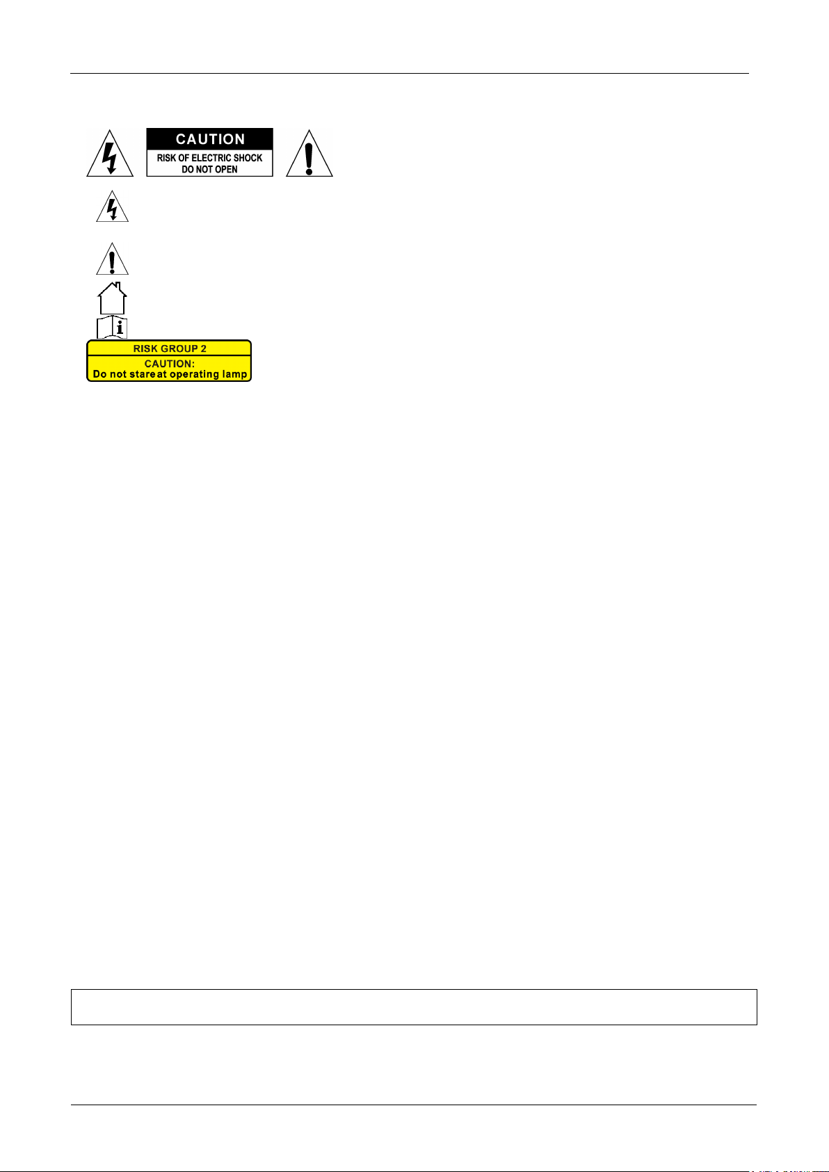
The lightning flash with arrowhead symbol within the equilateral triangle is intended to alert the
use or the presence of un-insulated “dangerous voltage” within the product’s enclosure that may
be of sufficient magnitude to constitute a risk of electric shock.
The exclamation point within the equilateral triangle is intended to alert the user to the presence
of important operation and maintenance (servicing) instructions in the literature accompanying
this appliance.
This symbol means: indoor use only
This symbol means: Read instructions
CAUTION: Do not stare at operating lamp.
May be harmful to the eyes.
Page 5
ENGLISH
USER MANUAL
JB SYSTEMS®
3/12
CLUBSPOT
OVERHEAD RIGGING
• Important: The installation must be
carried out by qualified service personal
only. Improper installation can result in
serious injuries and/or damage to
property. Overhead rigging requires
extensive experience! Working load limits
should be respected, certified installation
materials should be used, the installed
device should be inspected regularly for
safety.
• Make sure the area below the installation
place is free from unwanted persons during
rigging, de-rigging and servicing.
• Locate the fixture in a well ventilated spot, far
away from any flammable materials and/or
liquids. The fixture must be fixed at least
50cm from surrounding walls.
• The device should be installed out of reach of
people and outside areas where persons
may walk by or be seated.
• Before rigging make sure that the installation area can hold a minimum point load of 10times the device’s
weight.
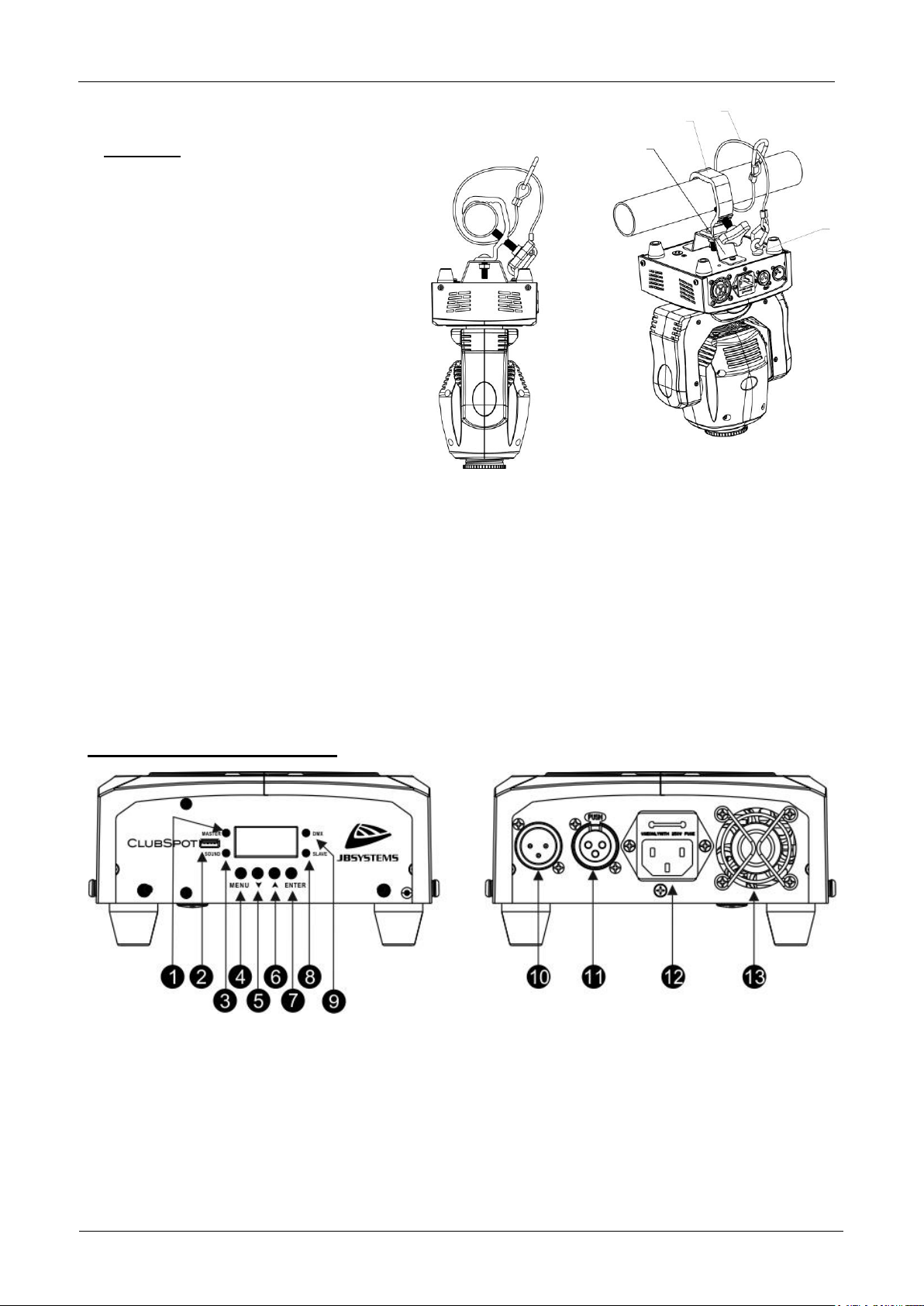
• Always use a certified safety cable (number 3 on the picture) that can hold 12 times the weight of the
device when installing the unit. This secondary safety attachment should be installed in a way that no part
of the installation can drop more than 20cm if the main attachment fails.
• The device should be well fixed; a free-swinging mounting is dangerous and may not be considered!
• Don’t cover any ventilation openings as this may result in overheating.
• The operator has to make sure that the safety-relating and machine-technical installations are approved by
an expert before using them for the first time. The installations should be inspected every year by a skilled
person to be sure that safety is still optimal.
HOW TO SET UP THE UNIT
FRONT + BACK PANEL:
1. [MASTER] : This LED lits when the CLUBSPOT is in Master mode.
2. M-DMX INPUT: Please note that this USB-connector is NOT used for updates or to connect the unit to a
PC! Instead this USB-connector makes it very easy to add wireless DMX to the unit! Just add the
(optional) WTR-DMX DONGLE from BRITEQ® and you will get wireless DMX! Moreover you will be able
to connect other DMX-controlled equipment to the DMX-output so you can share the wireless DMX
function with all connected units! No extra settings to be made in the setup menu, just follow the
procedure in the user manual supplied with the WTR-DMX DONGLE from BRITEQ®. The separate
WTR-DMX DONGLE is available from WWW.BRITEQ-LIGHTING.COM (order code: 4645)
3. [SOUND]: This LED reacts to the audio when the CLUBSPOT is in sound mode.
4. [MENU]: press this button to go back to the main menu or to leave submenus.
Page 6

ENGLISH
USER MANUAL
JB SYSTEMS®
4/12
CLUBSPOT
5. [▼] button : press this button to go down in the menu.
6. [▲] button : press this button to go up in the menu.
7. [ENTER]: press this button to confirm the selected function in the menu
8. [SLAVE]: This LED lits when the CLUBSPOT is in Slave mode.
9. [DMX]: This LED lits when a DMX-signal is present.
10. DMX INPUT connector 3pin XLR Male.
11. DMX OUTPUT connector 3p XLR Female.
12. MAINS INPUT with IEC14 socket and integrated fuse holder, connect the
supplied mains cable here.
13. FAN for cooling the electronic components in the base of the machine.
MAIN MENU:
• To select any of the functions, press the [MENU] button and use the ▼ / ▲
buttons to browse the menu.
• Select the function with the [ENTER] button (the display blinks).
• Use ▼ and ▲ buttons to change the mode.
• Once the required mode is selected, press the [ENTER] button to select.
• Press the [MENU] button for about 2 seconds to store the setting and to
return to running mode. If you don’t do this, the setting will not be stored
and after about 8 seconds, the fixture will return to the previous running
mode.
DMX Address [Addr]
Used to set the starting address in a DMX setup.
• Press the [MENU] and ▲/▼ buttons until “[Addr]” is shown on the display.
• Press the [ENTER] button.
• Use ▼ and ▲ buttons to change the DMX512 address.
• Once the correct address shows on the display, press the [ENTER] button
to select it.
• Press the MENU button for about 2 seconds to store the setting and to
return to running mode.
Channel mode [ChMd]
Used to set the desired channel setup mode.
• Press the [MENU] and ▲/▼ buttons until “[ChMd]” is shown on the display.
• Press the [ENTER] button.
• Use ▼ and ▲ buttons to choose 5CH, 9CH or 11CH mode.
• Once the desired channel setup mode shows on the display, press the
[ENTER] button to select it.
• Press the [MENU] button for about 2 seconds to store the setting and to
return to running mode.
Show Mode [ShMd]
Used to choose the Show mode when used in standalone or
master/slave. Press the [MENU] and ▲/▼ buttons until “[ShMd]” is showing
on the display.
• Press the [ENTER] button.
• Use ▼ and ▲ buttons to select one of the available shows:
• [Sh 1]: (Show 1) Fixture is placed on the floor. Tilt movement angle
210°.
• [Sh 2]: (Show 2) Fixture is fixed under ceiling. Tilt movement angle
90°.
• [Sh 3]: (Show 3) Fixture is placed on a podium, in front of the
audience. The spot is always projecting to the audience’s direction; i.e.
in front of the stage. Pan movement angle (left to right to left): 160°.
Tilt movement angle: 90° (60° above horizon; 30° below horizon.)
• [Sh 4]: (Show 4) Fixture is fixed under ceiling on the stage. The spot
is mainly projecting in front of the stage. Pan movement angle (left to
right to left):160°. Tilt movement angle: 90° (vertically, front 75°; back
Page 7

ENGLISH
USER MANUAL
JB SYSTEMS®
5/12
CLUBSPOT
15°)
• Once the desired mode is shown on the display, press the [ENTER] button to select it.
• Press the [MENU] button for about 2 seconds to store the setting and to return to running mode.
REMARK: The first fixture always have to be set as Master. Check chapter “[Slave Mode]” for the
configuration.
Slave Mode [SLMd]
Used to make the slave unit work in opposite to the master or to work in complete sync.
• Press the [MENU] and ▲/▼ buttons until “[SLMd]” is shown on the display.
• Press the [ENTER] button.
• Use ▼ and ▲ button to select [Slave1] (normal) or [Slave2] (2 light show) mode.
• Once the right mode is shown on the display, press the [ENTER] button to select it.
• Press the [MENU] button for about 2 seconds to store the setting and to return to running mode.
Sound mode [Soun]
Used to activate or deactivate sound control.
• Press the [MENU] and [▲/▼] buttons until [Soun] is shown on the display.
• Press the [ENTER] button.
• Use [▲/▼] button to choose [oFF] (DMX or Master/slave control) or [on] (sound) mode.
• Once the right mode is shown on the display, press the [ENTER] button to select it.
• Press the [MENU] button for about 2 seconds to store the setting and to return to running mode.
Sound Sense [SEnS]
Used to set the sensitivity of the internal microphone
• Press the [MENU] and ▲/▼ buttons until “[SEnS]” is shown on the display.
• Press the [ENTER] button.
• Use ▼ and ▲ button to choose a value between “00” (very low sensitivity) and “100” (high sensitivity).
• Once the right value is shown on the display, press the [ENTER] button select it.
• Press the [MENU] button for about 2 seconds to store the setting and to return to running mode.
Blackout Mode [BLMd]
Determines how the projector should react when no DMX-signal is detected.
• Press the [MENU] and ▲/▼ buttons until “[BLMd]” is shown on the display.
• Press the [ENTER] button.
• Use ▼ and ▲ button to select one of the available blackout modes:
• [YES]: The unit will go in blackout mode as soon as no DMX is detected.
• [no]: The unit starts working in SOUND mode, based on the settings made in the setup menu.
• Once the right mode is shown on the display, press the [ENTER] button to select it.
• Press the [MENU] button for about 2 seconds to store the setting and to return to running mode.
Pan Inversion [iPAn]
Normal: Panning movement is not inversed.
Pan inversion: Panning movement is inversed
• Press the [MENU] and ▲/▼ buttons until “[iPAn]” is shown on the display.
• Press the [ENTER] button.
• Use ▼ and ▲ button to select “[no]” (normal) or “[YES]” (pan inversion) mode.
• Once the mode is selected, press the [ENTER] button to select it.
• Press the [MENU] button for about 2 seconds to store the setting and to return to running mode.
Tilt Inversion [ItLt]
Normal: Tilt movement is not inversed.
Tilt inversion: tilt movement is inversed
• Press the [MENU] and ▲/▼ buttons until “ItLt” is shown on the display.
• Press the [ENTER] button.
• Use ▼ and ▲ button to choose “[no]” (normal) or “[YES]” (tilt inversion) mode.
• Once the right mode is shown on the display, press the [ENTER] button to select it.
• Press the [MENU] button for about 2 seconds to store the setting and to return to running mode.
Page 8

ENGLISH
USER MANUAL
JB SYSTEMS®
6/12
CLUBSPOT
Led Display on/off [LEd]
Switches the LED display automatically off or not.
• Press the [MENU] and ▲/▼ buttons until “[Led]” is shown on the display.
• Press the [ENTER] button.
• Use ▼ and ▲ buttons to select “[on]” (display always lit) or “[oFF]” (display dark when not used).
• Once the right mode is shown on the display, press the [ENTER] button to select it.
• Press the [MENU] button for about 2 seconds to store the setting and to return to running mode.
Display Rotation [dISP]
Rotate the display over 180° (upside-down) or not.
• Press the [MENU] and ▲/▼ buttons until the display shows “dISP”.
• Press the [ENTER] button.
• Use ▼ and ▲ buttons to select “[no]” (normal display always lit) or “[YES]” (display upside-down).
• Once the right position is shown on the display, press the [ENTER] button to select it.
• Press the [MENU] button for about 2 seconds to store the setting and to return to running mode.
Auto Test [tESt]
Used to activate the internal “self-test” program which checks all possibilities of the unit.
• Press the [MENU] and ▲/▼ buttons until the display shows “[tESt]”.
• Press the [ENTER] button to start the internal self-test program.
• To go back to the functions press the [MENU] button for about 2 seconds.
Temperature inside the unit [tEMP]
Used to show the temperature inside the unit
• Press the [MENU] and ▲/▼ buttons until the display shows “[tEMP]”.
• Press the [ENTER] button to show the internal LED temperature of the unit on the display.
• To go back to the functions press the [MENU] button again.
If you want to go back to normal running mode: press the [MENU] button for about 2 seconds.
Fixture Time [FhrS]
Used to show the number of working hours of the unit.
• Press the [MENU] and ▲/▼ buttons until the display shows “[FhrS]”.
• Press the [ENTER] button to show the number of working hours in the display.
• To go back to the functions press the [MENU] button.
Reset [rESt]
Used to force a reset of the unit.
• Press the [MENU] and ▲/▼ buttons until the display shows “rESt”.
• Press the [ENTER] button to reset the unit.
REMARK: also check the chapter about the DMX-channel configuration of the unit to find out how you can
force a reset by DMX.
OFFSET MENU:
Used to adjust the home position of several functions: offset parameters for PAN, TILT, COLORS,
GOBOS and light output.
If you’re not already in the setup menu, just press the [MENU] button shortly to enter the setup menu.
• Now press the [ENTER] button for about 2 seconds to go into offset mode.
• Use ▼ and ▲ buttons to select the function you want to adjust : [PAN], [TILT], [Colo], [Gobo] and [5Ch]
• [EPAN] : adjustable from -127 to 127
• [ETILT] : adjustable from -127 to 127
• [Colo] : adjustable from -127 to 127
• [Gobo] : adjustable from -127 to 127
• [5Ch] : adjustable from 128 to 255 (is light output)
• Press the [ENTER] button.
• Use ▼ and ▲ buttons to adjust the home position
• Press the [ENTER] button to select your setting.
• Press the [MENU] button for about 2 seconds to store the setting and to return to running mode.
Page 9

ENGLISH
USER MANUAL
JB SYSTEMS®
7/12
CLUBSPOT
ELECTRICAL INSTALLATION + ADDRESSING
Important: The electrical installation should be carried out by qualified personal only,
according to the regulations for electrical and mechanical safety in your country.
Electrical installation for 1 standalone unit:
• Just insert the mains cable. The unit starts working immediately in stand-alone mode.
Remark: if there’s no output, please make sure to set the blackout mode [BLMd] of the projector to “no”
and sound sensitivity [SEnS] to a value over 50 (see previous chapter).
Electrical installation for two or more units in master/slave:
In this mode the units will show a synchronized show, working to the rhythm of the beat.
• Connect the units together using good quality balanced microphone cables. The first unit in the chain
has to be configured as the master, the other units as slave1 or slave2.
• Make sure that all units are connected to the mains.
• Done!
Remark: if there’s no output, please make sure to set the blackout mode [BLMd] of the MASTER projector
to “no” and sound sensitivity [SEnS] to a value over 50 (see previous chapter).
Electrical installation in DMX-mode:
• The DMX-protocol is a widely used high speed signal to control intelligent light equipment. You need to
“daisy chain” your DMX controller and all the connected units with a good quality balanced cable.
• Both XLR-3pin and XLR-5pin connectors are used, however XLR-3pin is more popular because these
cables are compatible with balanced audio cables.
Pin layout XLR-3pin:
Pin1 = GND ~ Pin2 = Negative signal (-) ~ Pin3 = Positive signal (+)
Pin layout XLR-5pin:
Pin1 = GND ~ Pin2 = Negative signal (-) ~ Pin3 = Positive signal (+) ~ Pins4+5 not used.
• To prevent strange behavior of the light effects, due to interferences, you must use a 90Ω to 120Ω
terminator at the end of the chain. Never use Y-splitter cables, this simply won’t
work!
• Make sure that all units are connected to the mains.
• Each light effect in the chain needs to have its proper starting address so it knows
which commands from the controller it has to decode. In the next section you will
learn how to set the DMX addresses.
HOW TO SET THE RIGHT STARTING ADDRESS:
Refer to the previous chapter (DMX Address [Addr]) to learn how to set the starting address on this unit. The
starting address of each unit is very important. Unfortunately it is impossible to tell you in this user manual
which starting addresses you have to set because this completely depends on the controller you will use…
So please refer to the user manual of your DMX-controller to find out which starting addresses you must set.
Page 10

ENGLISH
USER MANUAL
JB SYSTEMS®
8/12
CLUBSPOT
DMX-CONFIGURATION OF THE CLUBSPOT IN 5, 9 AND 11CH MODE:
5CH Mode :
DMX
Channel
DMX-value
function
remarks
1
000-007
Standby
008-255
Dimmer 0 - 100%
2
000-007
No function
008-131
Strobe (slow - fast)
132-139
Full on
140-181
Close-open
Fast -> slow
182-189
Full on
190-231
Open-close
Fast -> slow
232-239
Full on
240-247
Random strobe
248-255
Full on
3
000-007
No function
008-037
Colors
Red
038-067 Green
068-097 Blue (dark)
098-127 Yellow
128-157 Orange
158-187 Blue
188-217 Purple
218-247 White
248-255
Rainbow
Fast
4
000-007
No function
Open (white)
008-037
Gobos
Gobo 1
038-067 Gobo 2
068-097 Gobo 3
098-127 Gobo 4
128-157 Gobo 5
158-187 Gobo 6
188-217 Gobo 7
218-247 Open (white)
248-255
Rainbow
Fast
5
000-007
HOLD (FREEZE)
008-255
AUTOMATIC PROGRAMS
PAN/TILT
9CH Mode :
DMX
Channel
DMX-value
function
remarks
1
000-255
Pan
2
000-255
Tilt
Page 11

ENGLISH
USER MANUAL
JB SYSTEMS®
9/12
CLUBSPOT
3
000-255
Pan/Tilt Speed
4
000-255
Dimmer 0 - 100%
5
000-007
No function
008-131
Strobe (slow - fast)
132-139
Full on
140-181
Close-open
Fast -> slow
182-189
Full on
190-231
Open-close
Fast -> slow
232-239
Full on
240-247
Random strobe
248-255
Full on
6
000-007
No function
Open (white)
008-015
Colors
Red
016-023 Green
024-031 Blue (dark)
032-039 Yellow
040-047 Orange
048-055 Blue
056-063 Purple
064-071
Split colors
White/red
072-079 Red/green
080-087 Green/blue
088-095 Blue/yellow
096-103 Yellow/orange
104-111 Orange/blue
112-119 Blue/purple
120-127 Purple/white
128-191
Rainbow
Slow -> fast
192-255
Rainbow reverse
Slow -> fast
7
000-007
Gobo
Open (white)
008-015 Gobo 1
016-023 Gobo 2
024-031 Gobo 3
032-039 Gobo 4
040-047 Gobo 5
048-055 Gobo 6
056-063 Gobo 7
064-071
Shaking gobos
Shaking open (white) slow->fast
072-079
Shaking gobo 1 (slow->fast)
080-087
Shaking gobo 2 (slow->fast)
088-095
Shaking gobo 3 (slow->fast)
096-103
Shaking gobo 4 (slow->fast)
104-111
Shaking gobo 5 (slow->fast)
112-119
Shaking gobo 6 (slow->fast)
120-127
Shaking gobo 7 (slow->fast)
Page 12

ENGLISH
USER MANUAL
JB SYSTEMS®
10/12
CLUBSPOT
128-191
Rainbow
Slow -> fast
192-255
Rainbow reverse
Slow -> fast
8
000-127
No function
Open (white)
128-255
Programs
Sound controlled
9
000-240
No function
241-255
RESET
Reset fixture (after 3s)
11CH Mode :
DMX
Channel
DMX-value
function
remarks
1
000-255
Pan
2
000-255
Pan fine
3
000-255
Tilt
4
000-255
Tilt fine
5
000-255
Pan/Tilt Speed
6
000-255
Dimmer 0 - 100%
7
000-007
No function
008-131
Strobe (slow - fast)
132-139
Full on
140-181
Close-open
Fast -> slow
182-189
Full on
190-231
Open-close
Fast -> slow
232-239
Full on
240-247
Random strobe
248-255
Full on
8
000-007
No function
Open (white)
008-015
Colors
Red
016-023 Green
024-031 Blue (dark)
032-039 Yellow
040-047 Orange
048-055 Blue
056-063 Purple
064-071
Split colors
White/red
072-079 Red/green
080-087 Green/blue
088-095 Blue/yellow
096-103 Yellow/orange
104-111 Orange/blue
112-119 Blue/purple
120-127 Purple/white
128-191
Rainbow
Slow -> fast
192-255
Rainbow reverse
Slow -> fast
9
000-007
Gobo
Open (white)
008-015 Gobo 1
Page 13

ENGLISH
USER MANUAL
JB SYSTEMS®
11/12
CLUBSPOT
016-023 Gobo 2
024-031 Gobo 3
032-039 Gobo 4
039-047 Gobo 5
048-055 Gobo 6
056-063 Gobo 7
064-071
Shaking gobos
Shaking open (white) slow->fast
072-079
Shaking gobo 1 (slow->fast)
080-087
Shaking gobo 2 (slow->fast)
088-095
Shaking gobo 3 (slow->fast)
096-103
Shaking gobo 4 (slow->fast)
104-111
Shaking gobo 5 (slow->fast)
112-119
Shaking gobo 6 (slow->fast)
120-127
Shaking gobo 7 (slow->fast)
128-191
Rainbow
Slow -> fast
192-255
Rainbow reverse
Slow -> fast
10
000-127
No function
Open (white)
128-255
Programs
Sound controlled
11
000-240
No function
241-255
RESET
Reset fixture (after 3s)
MAINTENANCE
• Make sure the area below the installation place is free from unwanted persons during servicing.
• Switch off the unit, unplug the mains cable and wait until the unit is cooled down.
During inspection the following points should be checked:
• All screws used for installing the device and any of its parts should be tightly fastened and may not be
corroded.
• Housings, fixations and installations spots (ceiling, truss, suspensions) should be totally free from any
deformation.
• When an optical lens is visibly damaged due to cracks or deep scratches, it must be replaced.
• The mains cables must be in impeccable condition and should be replaced immediately when even a
small problem is detected.
• In order to protect the device from overheat the cooling fans (if any) and ventilation openings should be
cleaned monthly.
• The interior of the device should be cleaned annually using a vacuum cleaner or air-jet.
• The cleaning of internal and external optical lenses and/or mirrors must be carried out periodically to
optimize light output. Cleaning frequency depends on the environment in which the fixture operates: damp,
smoky or particularly dirty surroundings can cause greater accumulation of dirt on the unit’s optics.
• Clean with a soft cloth using normal glass cleaning products.
• Always dry the parts carefully.
• Clean the external optics at least once every 30 days.
• Clean the internal optics at least every 90 days.
Attention: We strongly recommend internal cleaning to be carried out by qualified personnel!
Page 14

ENGLISH
USER MANUAL
JB SYSTEMS®
12/12
CLUBSPOT
SPECIFICATIONS
This unit is radio-interference suppressed. This product meets the requirements of the current European and
national guidelines. Conformity has been established and the relevant statements and documents have been
deposited by the manufacturer.
Mains Input: AC 100 - 240V, 50/60Hz
Power consumption: 60 Watt (max)
Fuse: 250V 3.15A slow blow (20mm glass)
Power connections: IEC14
DMX connections: 3pin-XLR male / female
DMX channels used: 5ch, 9ch, 11ch
Lamp: 35W LED Engine
Beam Angle: 12°
Color wheel: 7 colors + open
GOBO wheel: 7 fixed gobos
IP-Rating: IP20
Operating temperature (Ta): 0°C to 40°C
Size: see drawings
Weight: 3,5 kg
Every information is subject to change without prior notice
You can download the latest version of this user manual on our website: www.jb-systems.eu
Page 15

Page 16

 Loading...