

Page 1
Page 2
Page 3
ENGLISH USER MANUAL
CAUTION
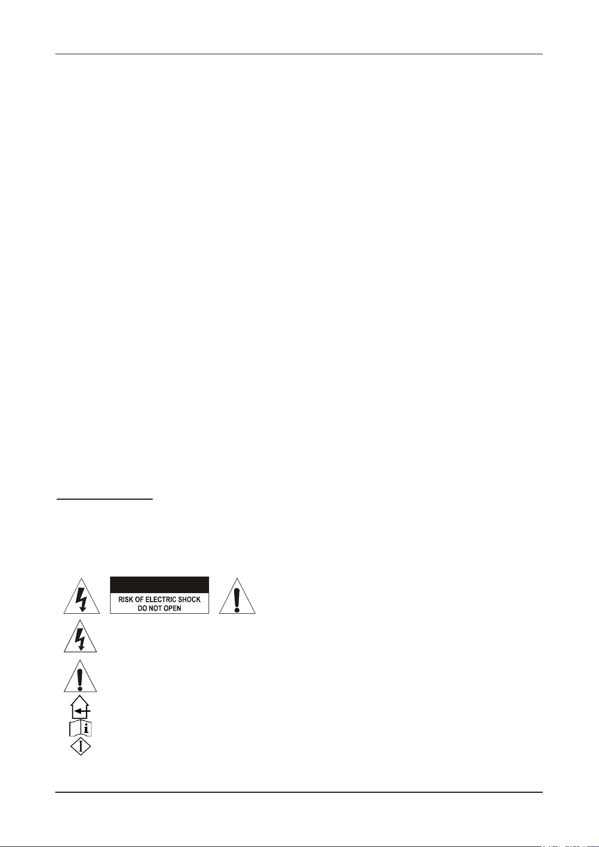
CAUTION: To reduce the risk of electric shock, do not
remove the top cover. No user-serviceable parts inside.
Refer servicing to qualified service personnel only.
The lightning flash with arrowhead symbol within the equilateral triangle is intended to alert the
use or the presence of un-insulated “dangerous voltage” within the product’s enclosure that may
be of sufficient magnitude to constitute a risk of electric shock.
The exclamation point within the equilateral triangle is intended to alert the user to the presence of
important operation and maintenance (servicing) instructions in the literature accompanying this
appliance.
This symbol means: indoor use only
This symbol means: Read instructions
This symbol means: Safety Class I appliance
OPERATION MANUAL
Thank you for buying this JB Systems® product. To take full advantage of all possibilities, please read these
operating instructions very carefully.
FEATURES
This unit is radio-interference suppressed. This appliance meets the requirements of the current European
and national guidelines. Conformity has been established and the relevant statements and documents have
been deposited by the manufacturer.
13 inputs on 7 channels (3 mics, 5 line, 2phonos or 2USB, 1 AUX)
2 USB connections (USB1 is Bidirectional) for connection to PC/Mac.
Internal WMA, WAV and MP3 mediaplayer for USB memory sticks and SD card (up to 16GB)
3 separate balanced microphone inputs with talkover function
Treble, mid, bass controls on all channels
Assignable crossfader
1 Master output and 1 Booth output with individual level control.
Master with balanced XLR outputs
LED VU-meters on input channels and Master
Pre-fade listening with cue mix option
BEFORE USE
Before you start using this unit, please check if there’s no transportation damage. Should there be any, do
not use the device and consult your dealer first.
Important: This device left our factory in perfect condition and well packaged. It is absolutely necessary
for the user to strictly follow the safety instructions and warnings in this user manual. Any damage caused
by mishandling is not subject to warranty. The dealer will not accept responsibility for any resulting defects
or problems caused by disregarding this user manual.
Keep this booklet in a safe place for future consultation. If you sell the fixture, be sure to add this user
manual.
To protect the environment, please try to recycle the packing material as much as possible.
Check the contents:
Check that the carton contains the following items:
Mixer
Operating instructions
SAFETY INSTRUCTIONS:
JB SYSTEMS 1/7 Club7usb
Page 4

ENGLISH USER MANUAL
This appliance must be earthed in order to comply with safety regulations.
To prevent fire or shock hazard, do not expose this appliance to rain or moisture.
To avoid condensation to be formed inside, allow the unit to adapt to the surrounding temperatures when
bringing it into a warm room after transport. Condense sometimes prevents the unit from working at full
performance or may even cause damages.
This unit is for indoor use only.
Don’t place metal objects or spill liquid inside the unit. No objects filled with liquids, such as vases, shall be
placed on this appliance. Electric shock or malfunction may result. If a foreign object enters the unit,
immediately disconnect the mains power.
No naked flame sources, such as lighted candles, should be placed on the appliance.
Don’t cover any ventilation openings as this may result in overheating.
Prevent use in dusty environments and clean the unit regularly.
Keep the unit away from children.
Inexperienced persons should not operate this device.
Maximum save ambient temperature is 40°C. Don’t use this unit at higher ambient temperatures.
Minimum distances around the apparatus for sufficient ventilation is 5cm.
Always unplug the unit when it is not used for a longer time or before you start servicing.
The electrical installation should be carried out by qualified personal only, according to the regulations for
electrical and mechanical safety in your country.
Check that the available voltage is not higher than the one stated on the rear panel of the unit.
The socket inlet shall remain operable for disconnection from the mains.
The power cord should always be in perfect condition. Switch the unit immediately off when the power cord
is squashed or damaged. It must be replaced by the manufacturer, its service agent or similarly qualified
persons in order to avoid a hazard.
Never let the power-cord come into contact with other cables!
When the power switch is in OFF position, this unit is not completely disconnected from the mains!
In order to prevent electric shock, do not open the cover. Apart from the mains fuse there are no user
serviceable parts inside.
Never repair a fuse or bypass the fuse holder. Always replace a damaged fuse with a fuse of the same
type and electrical specifications!
In the event of serious operating problems, stop using the appliance and contact your dealer immediately.
Please use the original packing when the device is to be transported.
Due to safety reasons it is prohibited to make unauthorized modifications to the unit.
CAUTION: Danger of explosion if battery is incorrectly replaced. Replace only with the same or equivalent
type. The battery shall never be exposed to excessive heat such as sunshine, fire, ….
INSTALLATION GUIDELINES:
Install the unit in a well-ventilated location where it will not be exposed to high temperatures or humidity.
Placing and using the unit for long periods near heat-generating sources such as amplifiers, spotlights, etc.
will affect its performance and may even damage the unit.
The unit can be mounted in 19-inch racks. Attach the unit using the 4 screw holes on the front panel. Be
sure to use screws of the appropriate size. (screws not provided) Take care to minimize shocks and
vibrations during transport.
When installed in a booth or flight case, please make sure to have good ventilation to improve heat
evacuation of the unit.
To avoid condensation to be formed inside, allow the unit to adapt to the surrounding temperatures when
bringing it into a warm room after transport. Condense sometimes prevents the unit from working at full
performance.
CLEANING THE MIXER:
Clean by wiping with a polished cloth slightly dipped with water. Avoid getting water inside the unit. Do not
use volatile liquids such as benzene or thinner which will damage the unit.
JB SYSTEMS 2/7 Club7usb
Page 5

ENGLISH USER MANUAL
CONNECTIONS
Except for microphones, headphone and master outputs, all connections are cinch. Use good quality cinchcinch cables to prevent bad audio quality.
For more information on connections, please refer to the next chapter.
Be sure to turn off the mixer before you make changes to the different connections.
In this manual we talk about “line inputs”. This is a global name for inputs with a level up to 2V. This includes
tuners, videos, CD-players, etc.
Both USB connections will be detected as a sound card on your computer. The USB1 connection is
bidirectional (play/record music simultaneously)
CONTROLS AND FUNCTIONS (FRONT)
JB SYSTEMS 3/7 Club7usb
Page 6

ENGLISH USER MANUAL
1. [LEVEL]: Adjusts the input level on each channel. Use this control to adjust the level on the VU-meter at
about 0dB.
2. CHANNEL VU METER: Each channel has its own LED VU-meter so you can adjust the gain level (1)
very quickly. Make sure the levels do not exceed 0dB (or 100%). The audio risks to be distorted when
the signal level comes in the red zone of the VU-meter.
3. INPUT SOURCE SELECTOR: Used to select the correct input on each channel: Phono, line, USB, aux
or CD. There are also additional input selectors on the back.
Hint: Line, Aux, CD, Tuner, etc… are different names for inputs with almost the same signal levels.
4. [TALKOVER]: Use the switch to automatically mute the input channels 1 to 4 while you are talking
through a microphone connected to [MIC 1], [MIC 2] or [MIC 3]. You can adjust the amount of muting on
input channels 1 to 4. The more you turn the talkover level to the right, the more these channels are
muted while talking through one of the microphones connected to [MIC 1], [MIC 2] or [MIC 3].
5. [AUX]: 3.5mm stereo mini-jack input to connect external sources (for example : smartphone, tablet or
PC). This input is controlled by channel 4. Connecting an external source will take priority over the
internal player.
6. [BALANCE]: used to adjust the balance between left and right output on the [Master].
7. [POWER]: The blue led is lit when the mixer is turned on.
8. [MASTER] VU METERS: Monitors the output level of the [master]. Make sure the levels do not exceed
0dB (or 100%). The audio will be distorted when the signal level comes in the red zone of the VU-meter.
9. [MASTER]: Used to adjust the level of the balanced [Master] output.
10. [BOOTH]: Used to adjust the level of the unbalanced [BOOTH] output.
11. [SD-CARD READER]: for the use of SD cards (max. 16GB – FAT 32). The card reader is controlled by
channel 4. The inserted SD card will have priority above the USB memory stick. It is NOT possible to use
both SD card and USB stick simultaneously.
12. [USB socket]: for the use of USB memory sticks (max. 16GB – FAT 32) with a one level folder structure
for replay of WMA, WAV and MP3 files. Note that this socket does NOT support USB hard drives,
neither for memory size nor for power requirements. The USB memory stick is controlled by channel 4.
13. Display: shows information such as playing time, track name, …
A. Time Display: shows elapsed/remaining
time while the media player is used.
B. Elapsed time: is displayed while “E” is lit.
C. Remaining time: is displayed while “R” is lit.
D. Not used!
E. 8-Digit Text Readout: The file name of the
currently playing track is shown, with its first
30 digits scrolling through the display. Note
that this is NOT an ID3 tag readout, but a file
name readout, so files must be named
properly to yield a sensible displayed
content. The display will show the file name
and alternate with the folder name the current file is located in. Whether at a specific time the file
or the folder name is displayed, is indicated by the respective symbols (F/G)
F. Folder Name Display Indicator: This indicator shows that the current content of the text
readout (E) is a folder name.
G. File Name Display Indicator: This indicator shows the current content of the text readout (E) is
a file name.
H. FM-indicator: Not used!
I. Play Sequence Indicator: This indicator shows whether the unit is set to straight sequential or
random play sequence. The setting can be altered by the play sequence button (15).
J. Play Mode Indicator: Based on the selection made by the play mode button (14), this part of
the display shows the letters “SPL”, “SLO”, “ACO” or ALO“.
K. Player status: shows if the player is in play, pause or stop mode. See play/pause button (16).
14. Play mode selector: Selects between the different playback modes of the media player:
SPL = Single Play: The player stops after playing the current song once.
SLO = Single Loop: The player loops the current song endlessly.
ACO = All Continuous: The player continues after playing the current song. The next song is
determined by the chosen sequence. The player stops after the sequence is executed once.
ALO = All Loop: The player continues after playing the current song. The next song is
determined by the chosen sequence. The player repeats the sequence endlessly.
This selected play mode is displayed in the display (J).
JB SYSTEMS 4/7 Club7usb
Page 7

ENGLISH USER MANUAL
15. Play sequence selector: two play sequences are available:
STRAIGHT play sequence: The next song is determined by alphanumerical sorting.
RANDOM play sequence: The next song is determined by random choice.
16. Media PLAY/PAUSE/STOP button: Press briefly to toggle between PLAY (backlight lit) and PAUSE
(backlight flashing) mode. Press for longer than 2 seconds to change into STOP status (backlight off).
17. Folder level button: Press the button to go to folder level and use Rotary dial (19) to select the desired
folder.
18. Time Display selector: Selects between elapsed/remaining time display. The display shows [E] for
Elapsed time or [R] for Remaining time (see display “B” and “C”) and is always related to track currently
playing.
19. Rotary dial: Turn the dial knob to choose a song or a folder. Press the the dial knob to confirm your
choice. Your choice is immediately active.
20. HEADPHONE JACK: You can monitor all inputs/outputs when you connect any modern stereo
headphone to this 6.3mm jack.
21. [CUE VOLUME]: Used to control the output level of the headphone output.
22. [CUE MIX]: With this knob you can mix the master output and any of the input channels through the
headphone output (20):
Put the knob in the extreme left position to monitor a selected PFL signal (26).
Put the knob in the extreme right position to hear the master output.
Put the knob in any other position to hear a mix of the two signals.
This option makes it possible to check your mix before you put it on the master output.
23. [CROSSFADER] ASSIGN: Selects the input channels to be used with the crossfader (24).
24. [CROSSFADER]: With this VCA fader you can mix over between the channels you selected with the
crossfader assign selectors (23). The crossfader only works when you move the selected channel faders
(27) to the desired level!
25. [CROSSFADER] ON/OFF: Switches on and off the crossfader (24).
26. [PFL SELECTOR]: Used to select the source (CH-1 to CH-4) to be monitored via the headphones
output.
27. CHANNEL FADER: Used to set the level of each channel separately.
28. 3-BAND TONE CONTROLS: The frequency [(HIGH-MID-LOW)] of each channel can be controlled
separately over a range from -26dB to +12dB. In the center position the tone control is flat.
29. ON/OFF SWITCH MIC 1-2-3: Switches on and off the microphones (MIC 1 – MIC 2 – MIC 3)
30. LEVEL MIC 1-2-3: Adjusts the input level on the microphone channels (MIC 1 – MIC 2 – MIC 3). Use
this control to adjust the level on the VU-meter at about 0dB.
31. MIC INPUT JACK: Combo jack. Accepts either a balanced microphone with an XLR connector or an
unbalanced microphone with 1/4” mono jack.
JB SYSTEMS 5/7 Club7usb
Page 8

ENGLISH USER MANUAL
CONTROLS AND FUNCTIONS (rear)
32. MAINS CABLE: connect this cable to a 230V/50Hz mains outlet. Before use, inspect the cable to be
sure it’s not damaged!
33. POWER SWITCH: Used to turn the power of the mixer on and off. The blue led (7) is lit when the mixer
is turned on.
34. MASTER BALANCED OUTPUT: The XLR-connectors can be used to connect this mixer to any
balanced amplifier input, using special balanced signal cables.
35. [BOOTH] OUTPUT: The “[Booth]” output carries the same signal but can be controlled independently by
the “[BOOTH]” (10). Use the output to connect unbalanced amplifiers.
36. RECORD OUTPUT: Carries the same signal as the master outputs but is not influenced by the master
level and balance controls. Used to connect analog recording equipment. You can also connect a
computer for direct digital recording on the USB1 connection (46).
37. INPUT CHANNEL 4: used to connect line level audio signals. The input source selector (3) on the front
determines which input will be active.
38. INPUT CHANNEL 3 (CD): used to connect line level audio signals. The input source selector (3) on the
front has to be put to “[CD]”.
39. INPUT CHANNEL 3 (USB2/PH): used to connect phono level audio signals. The input source selector
(3) on the front has to be put to “[PHONO/USB2]”. Press switch (47) on the rear of the mixer to select the
phono input.
40. USB1/PH SWITCH: This switch makes it possible to switch between the phono input (41) and the USB1
input (46) on channel 3.
41. INPUT CHANNEL 2 (USB1/PH): used to connect phono level audio signals. The input source selector
(3) on the front has to be put to “[PHONO/USB1]”. Press switch (40) on the rear of the mixer to select the
phono input.
42. INPUT CHANNEL 2 (CD): used to connect line level audio signals. The input source selector (3) on the
front has to be put to “[CD]”.
43. LINE INPUT CHANNEL 1 (LN): used to connect a line level audio signal to channel 1. The input selector
(3) on the front has to be put to “[LINE]”.
44. LINE INPUT CHANNEL 1 (CD): used to connect a line level audio signal to channel 1. The input
selector (3) on the front has to be put to “[CD]”.
45. USB CONNECTION [USB2]: USB connection (USB2 for CH3). You can connect any PC through this
USB connection. The PC/Mac will detect your mixer as a sound card, normally no drivers are needed.
46. USB CONNECTION [USB1]: bidirectional USB connection (USB1 for CH2). You can connect any PC
through this USB connection. The PC/Mac will detect your mixer as a sound card, normally no drivers
are needed. Since the USB port is bidirectional you are able to play music on your computer and mix this
music with other sources like CD, phono, etc. At the same time you can record your mix on your
computer with the same USB connection
47. USB2/PH SWITCH: This switch makes it possible to switch between the phono input (39) and the USB2
input (45) on channel 2.
48. GROUND (GND) CONNECTION: Many Turntables have a GND-connection. It is preferable to connect
this signal ground to the GND-connector. If your turntable does not have a ground wire, you don’t have
to use this connector.
JB SYSTEMS 6/7 Club7usb
Page 9

ENGLISH USER MANUAL
SPECIFICATIONS
Power Supply: AC 220-240V, 50Hz
Power Consumption: 18W
Fuse: 250V/500mA slow blow 20mm glass fuse
Frequency response: 20-22.000Hz (+/-3dB)
THD: <0.07% (line input)
S/N Ratio (IHF-A): >78dB @ 1kHz.
USB connections: USB 2.0, one = bidirectional (44,1kHz / 16bit)
Windows® & MacOS® compatible.
USB cable (not included): Lmax = 3m
MEDIA FORMATS:
Possible MP3 file extensions: .mp3 ~ .MP3 ~ .mP3 ~ .Mp3
Possible WMA file extensions: .WMA ~ .wma
Possible WAV file extensions: .WAV ~ .wav
USB file system: FAT 32
Max. USB-memory capacity: 16GB
MP3 FORMATS PLAYBACK:
MPEG1 Layer3 (ISO/IEC11172-3): mono / stereo sampled at: 32 - 44,1 - 48kHz
Bitrates: 32 – 320 Kbps
Bitrate modes: CBR (Constant Bitrate), VBR (Variable Bitrate)
Mic inputs: 15.5mV @ 35kΩ
Line/CD inputs: 3.1V @ 47kΩ
Phono inputs: 30.8mV @ 47kΩ
Record output: 1kΩ
Booth output: unbalanced, max +18 dBu, 550Ω
Master output: balanced, max +18 dBu, 470Ω
Channel tone controls:
High: +10dB / -12dB @ 10kHz
Mid: +12dB / -24dB @ 1.3kHz
Low: +12dB / -29dB @ 50Hz
Microphone tone controls:
High: +16dB / -16dB @ 10kHz
Mid: +12dB / -12dB @ 2.5kHz
Low: +15dB / -15dB @ 70Hz
Headphone: max 120mW @ 75 Ohm/1% THD
Dimensions: 483(W) x 78(D) x 222(H) mm
Weight: 4,45kg
The information is subject to change without prior notice
You can download the latest version of this user manual on our website: www.jb-systems.eu
JB SYSTEMS 7/7 Club7usb
Page 10

Page 11

Page 12

 Loading...