

Page 1

User’s Guide
Mode d’emploi
Gebruiksaanwijzing
Bedienungsanleitung
Instrucciones para el uso
Manual do utilizador
Page 2

ENGLISH
AX700 2
GENERAL
• AX700 Input Section is constructed by J-type fet tube and advanced
OP Circuit, together with DC Servo power. AX700 has a high
impedance, low noise and large range of frequency response.
AX700 has a protection function as follows:
• Power ON/OFF transmission, prevents against surges.
• DC protection at speaker output: the amplifier will automatically cut
off the link with the speakers when the amplifier has a defect.
• Thermal cut off protection: the amplifier will automatically cut off the
link with the speakers when the temperature is more than 85°.
• Short circuit current limited protection.
PRECAUTIONS
• Don’t put anything on top of the amplifier.
• Always use a power source of adequate capacity.
• Wait several minutes when turning the power amplifier ON/OFF
continiously.
• Don’t let the ventilation holes on the body of the amplifier get
• obstructed in any way.
• Input level can be adjusted via the gain switch of each channel.
• Output can be used with phone Jack or speakon.
• Don’t obstruct the cooling system on the rear panel.
• Before cleaning the amplifier, turn it off and cut off the power supply.
Wipe it with a dry cloth. Don’t use solvent or a chemical cloth.
• If there is a defect, disconnect the power cord and contact your
dealer.
Page 3
AX700 3
MAJOR OPERATING CONTROLS AND FUNCTIONS
FRONT PANEL
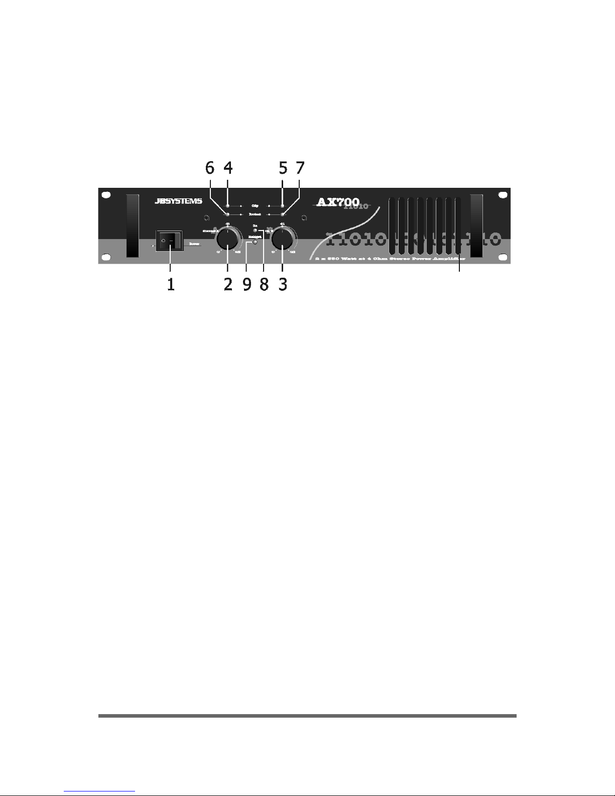
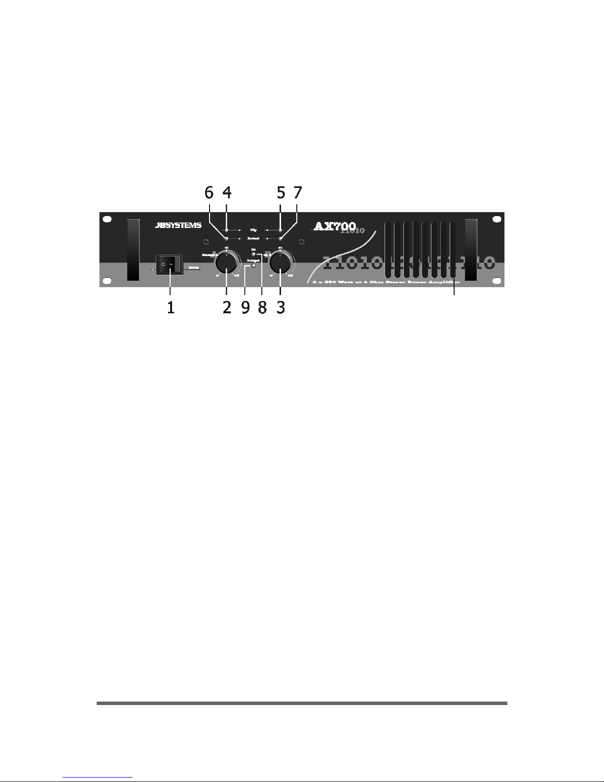
1. Power ON/OFF switch: When you turn on the amplifier, the power
ON/OFF transmission protection starts working, after 3-4 minutes
you hear a “kniak” sound. The amplifier is connected with the
speakers and is ready for use.
2. CH1 Input Level Control: Adjust it to the volume you need, adjust it
with the scale on the front panel that indicates the amount of attenuation applied to the input signal. Use this control only when
running the amplifier in Bridge mode.
3. CH2 Input Level Control: same as CH1.
4/5. CH1/CH2 Peak Level Indicator LED: the leds will light up when the
output has reached its peak level. When this occurs, turn down the
input level.
6/7. CH1/CH2 Protection Indicator LED: the leds will light up at the
following three situations:
• After turning on the power within 3-5 minutes and after turning
off the power.
• When the temperature of the power transistor is over 85°.
• When there is a defect.
8. Power ON/OFF LED: to indicate that the amplifier is connected to
the power source.
9. Bridge Mono Mode Indicator LED: to indicate that the amplifier
works in Bridge mode.
Page 4

AX700 4
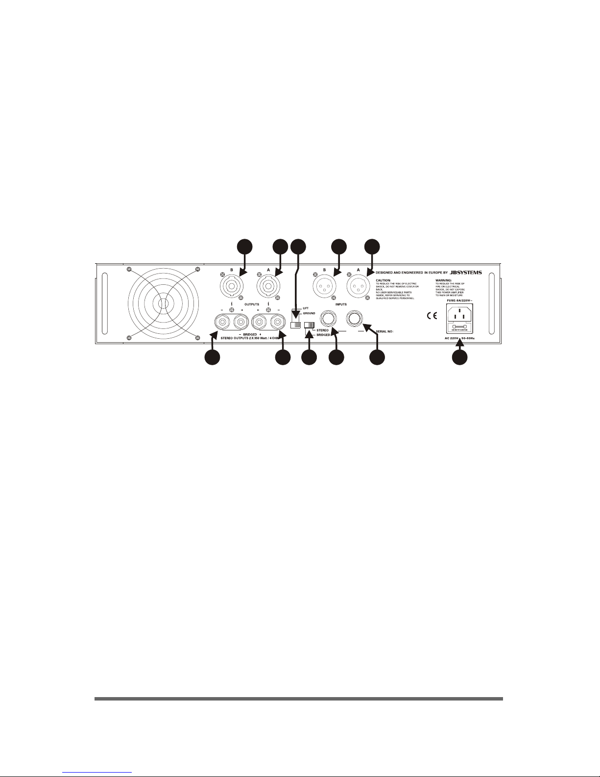
REAR PANEL
7. Mode Selector: two modes to select:
A. Stereo Mode
B. Bridge Mode (CH1 working): output voltage double
1. Standard Power Connector (Fuse Socket):
Attention: use the correct fuse when changed.
2.
3.
CH1/CH2 Output Connector: Use Speakon connector
CH1/CH2 Output Connector: Use Binding post connector
4. Ground Lift Switch.
5.
6.
CH1/CH2 Input Connector: Use a 1/4” connector
CH1/CH2 Input Connector: Use an XLR connector
3 3 5 57 1
2 6 642
STEREO OUTPUT SPEAKON:
(PIN1+/PIN2+)+, (PIN1-/PIN2-)-
BRIDGE OUTPUT SPEAKON:
A(PIN1+/PIN2+)+, B(PIN1+/PIN2+)-
OUTPUT WIRING:
JACK:
TIP: +
RING: SLEEVE: GND
XLR:
PIN1: GND
PIN2: +
PIN3: -
Page 5

SPECIFICATIONS
Power Supply ..................................................... 220V / 50-60 Hz
Power Consumption ............................................ Approx 700W at the
........................................................................ rated output
Output Power Stereo 8 Ohm ................................ 2 x 200W
Stereo 4 Ohm ..................................................... 2 x 350W
Bridge Mono 8 Ohm ............................................ 700W
Frequency Response ........................................... 20 Hz - 100 KHz /
........................................................................ -1 dB (at half power)
Slew Rate ......................................................... 60V/µ
THD .................................................................. 20 Hz-20 KHz ≤ 0.3%
Crosstalk ........................................................... ≥ 60dB (10KHz)
S/N Ratio ........................................................... ≥ 85 dB
Input Impedance ................................................ 20 KOhm
Dimensions (WxDxH) .......................................... 83 x 315 x 88 mm
Weight .............................................................. 14 Kg
AX700 5
Page 6

AX700 6
GENERAL
• L’AX-700 est basé sur une structure de type J-Fet et un circuit OP
avancé. Il dispose d’une haute impédance, ne génère qu’un faible
bruit de fond et dispose d’une large bande de fréquences.
• L’AX-700 offre les protections suivantes :
• protection contre la surcharge de courant au démarrage.
• protection des haut-parleurs en cas d’émission de courant
continu en sortie : l’amplificateur coupera automatiquement tout
signal aux haut-parleurs lorsqu’une défectuosité surviendra.
• protection thermique : coupure de tout signal de sortie vers les
haut-parleurs si la température excède les 85 °C.
• protection contre les courts-circuits.
PRECAUTIONS
• Ne déposer rien au-dessus de l’amplificateur.
• Utiliser toujours une source d’alimentation adaptée.
• Attendez quelques secondes lorsque l’amplificateur est activé.
• Faites attention de ne pas obstruer le trou de ventilation de l’appareil.
• Le niveau d’entrée peut être ajusté via le commutateur de gain de
chaque canal.
• La prise de sortie peut être soit une fiche jack mono soit un speakon.
• Pour le nettoyage de l’appareil, veillez à le retirer de l’alimentation,
utilisez un chiffon doux et n’utilisez aucun produit corrosif ou chiffon
imbibé d’un quelconque produit chimique.
• Si un défaut survient, déconnectez immédiatement l’amplificateur de
son alimentation et contactez votre dealer.
FRANCAIS
Page 7
AX700 7
Opérations de contrôle et fonctions.
FACE AVANT
1. Interrupteur d’alimentation ON/OFF: lorsque vous allumez
l’amplificateur, la protection de surcharge de tension se met en route
et vous entendrez un « kniak » après 3 ou 4 secondes.
L’amplificateur, connecté aux haut-parleurs, est alors opérationnel.
2. Commande du niveau d’entrée du canal 1: réglez le volume à votre
convenance à l’aide de la graduation qui vous indique le niveau
d’atténuation appliqué au signal d’entrée. Utilisez uniquement
cette commande lorsque vous êtes en mode bridge.
3. Commande de niveau d’entrée du canal 2 : idem que le canal 1 sauf
que cette commande n’est pas utilisée si vous êtes en mode bridge.
4/5. Témoin lumineux de pic du signal du canal 1 et 2 : ces témoins
s ‘allumeront si vous dépassez la limite permise du signal d’entrée.
Il vous faudra alors diminuer le niveau d’entrée afin que ces témoins
restent éteints.
6/7. Témoins lumineux de protection des canaux 1 et 2 :
Ces témoins s’allumeront dans les 3 cas suivants :
• lorsque vous allumez ou éteignez l’amplificateur et ce pendant 3
à 5 secondes.
• lorsque la température des transistors est supérieure à 85°C.
1. lorsqu’une défectuosité de l’appareil survient.
Page 8
AX700 8
8. Témoin lumineux de mise sous tension: indique que l’amplificateur
est connecté à l’alimentation.
9. Indicateur lumineux du mode bridge: indique que l’amplificateur
travaille sur le mode bridge.
FACE ARRIERE
7. Interrupteur de mode :
A. mode stereo
B. mode bridge (uniquement le canal 1):
la puissance de sortie est ainsi doublée.
3 3 5 57 1
2 6 642
STEREO OUTPUT SPEAKON:
(PIN1+/PIN2+)+, (PIN1-/PIN2-)-
BRIDGE OUTPUT SPEAKON:
A(PIN1+/PIN2+)+, B(PIN1+/PIN2+)-
OUTPUT WIRING:
JACK:
TIP: +
RING: SLEEVE: GND
XLR:
PIN1: GND
PIN2: +
PIN3: -
1. Prise d’alimentation avec fusible incorporé.
Attention ! utilisez toujours un fusible de même type et de même
valeur lorsque vous le remplacez.
2. Connecteurs du signal de sortie du canal 1 et 2: Speakon.
3. Connecteurs du signal de sortie du canal 1 et 2: Bornes a vis.
4. Commutateur de mise à la masse.
5. Prises du signal d’entrée du canal 1 et 2: Jack 1/4”
6. Prises du signal d’entrée du canal 1 et 2: connecteur XLR
Page 9

SPECIFICATIONS
Alimentation ....................................................... 220V / 50-60 Hz
Consommation Puissance .................................... ± 700W au sortie
........................................................................ concernant
Sortie Tension Stereo 8 Ohm ............................... 2 x 200W
Stereo 4 Ohm ..................................................... 2 x 350W
Bridge Mono 8 Ohm ............................................ 700W
Réponse en fréquence ......................................... 20 Hz - 100 KHz /
........................................................................ -1 dB (half power)
Slew Rate .......................................................... 60V/µ
THD .................................................................. 20 Hz-20 KHz ≤ 0.3%
Crosstalk ........................................................... ≥ 60dB (10KHz)
Ratio S/N ........................................................... ≥ 85 dB
Impédance d’entrée ............................................ 20 KOhm
Dimensions (WxDxH) .......................................... 83 x 315 x 88 mm
Poids ................................................................. 14 Kg
AX700 9
Page 10

AX700 10
ALGEMEEN
• De AX700 Ingangssectie is gebouwd met type J fet buis en
geavanceerd OP Circuit, samen met DC Servo stroom. De AX700
heeft een hoge impedantie, een groot frequentiebereik en maakt
weinig lawaai. De AX700 heeft volgende beveiligingsfuncties:
• Power ON/OFF transmissie, voorkomt schommelingen.
• DC beveiling aan de uitgang van de luidsprekers:
wanneer de versterker een defect heeft zal hij automatisch de
verbinding met de luidsprekers verbreken.
• Thermische verbrekingsbeveiliging: wanneer de temperatuur
hoger is dan 85° graden, zal de versterker automatisch de
verbinding met de luidsprekers verbreken.
• Beveiliging tegen kortsluiting.
VOORZORGEN
• Niets bovenop de versterker plaatsen.
• Gebruik steeds een electriciteitsbron met het geschikte vermogen.
• Wacht enkele minuten tussen het aan– en uitzetten van de versterker.
• De ventilatiegaten van de versterker nooit afdekken/blokkeren.
• Ingangsniveau kan worden aangepast met de versterkingsknop van elk
kanaal.
• Uitgang kan worden gebruikt met Jack of speakon.
• Het koelingsssysteem aan de achterkant nooit blokkeren.
• Zet de versterker uit en verbreek de voeding alvorens de versterker
schoon te maken. Veeg hem af met een droge doek. Gebruik geen
oplosmiddelen of chemische doek.
• In geval van defect, haal de kabel uit het contact en contacteer uw
verdeler.
NEDERLANDS
Page 11

AX700 11
BELANGRIJKSTE FUNCTIES
VOORAANZICHT
1. AAN/UIT schakelaar: Wanneer je de versterker aanzet, start de
stroom AAN/UIT transmissiebeveiliging, na 3-4 minuten hoor je een
’knak’ geluid. De versterker is aangesloten met de luidsprekers en is
klaar voor gebruik.
2. Kanaal 1 Ingangsniveaucontrole: Pas het aan tot het gewenste
volume, het kan worden aangepast met de schaal op het frontpaneel
die de hoeveelheid verzwakking van het ingangssignaal aangeeft.
Gebruik deze controle enkel wanneer de versterker in Bridge
methode staat.
3. Kanaal 2 Ingangsniveaucontrole: zelfde als kanaal 1.
4/5.Kanaal 1/kanaal 2 Hoogtepuntniveau Indicator LED: de leds zullen
oplichten wanneer de uitgang zijn hoogtepunt heeft bereikt.
Indien dit gebeurt, gelieve het ingangsniveau te verminderen.
6/7. Kanaal 1/kanaal 2 Beveiligingsindicator LED:
de leds zullen oplichten in de volgende drie situaties:
• 3-5 minuten na het aanzetten van de stroom en na het uitzetten
van de stroom.
• Wanneer de temperatuur van de stroomgeleider meer is dan 85°.
• Wanneer er een defect is.
8. Stroom AAN/UIT LED: om aan te duiden dat de versterker op de
electriciteitsbron is aangesloten.
9. Bridge Mono Methode Indicator LED: om aan te duiden dat de
versterker in Bridge Methode werkt.
Page 12

AX700 12
ACHTERAANZICHT
7. Selectiemethode: twee methodes te selecteren:
A. Stereo
B. Bridge (kanaal 1 in werking): dubbele stroomuitgang
3 3 5 57 1
2 6 642
STEREO OUTPUT SPEAKON:
(PIN1+/PIN2+)+, (PIN1-/PIN2-)-
BRIDGE OUTPUT SPEAKON:
A(PIN1+/PIN2+)+, B(PIN1+/PIN2+)-
OUTPUT WIRING:
JACK:
TIP: +
RING: SLEEVE: GND
XLR:
PIN1: GND
PIN2: +
PIN3: -
1. Standaard Stroomaansluiting (met fitting voor zekering).
Opgepast: gebruik bij vervanging de juiste zekering.
2. Kanaal 1/kanaal 2 Aansluiting Uitgang: Speakon aansluitingen
3. Kanaal 1/kanaal 2 Aansluiting Uitgang: Draadaansluitingen
4. Groundlift: gebruik deze om eventuele brom te onderdrukken.
5.
6.
Kanaal 1/kanaal 2 Aansluiting Ingang: 1/4” jack aansluiting
Kanaal 1/kanaal 2 Aansluiting Ingang: XLR aansluiting
Page 13

SPECIFICATIES
Voeding ............................................................. 220V / 50-60 Hz
Stroomverbruik ................................................... Ongeveer 700W bij de
........................................................................ geldende uitgang
Uitgang Stroom Stereo 8 Ohm .............................. 2 x 200W
Stereo 4 Ohm ..................................................... 2 x 350W
Bridge Mono 8 Ohm ............................................ 700W
Frequentie ......................................................... 20 Hz - 100 KHz /
........................................................................ -1 dB (half power)
Slew Rate ......................................................... 60V/µ
THD .................................................................. 20 Hz-20 KHz ≤ 0.3%
Crosstalk ........................................................... ≥ 60dB (10KHz)
S/R Verhouding .................................................. ≥ 85 dB
Ingangsimpedantie ............................................. 20 KOhm
Afmetingen (WxDxH) .......................................... 83 x 315 x 88 mm
Gewicht ............................................................. 14 Kg
AX700 13
Page 14

AX700 14
ALLGEMEINES
• Die AX700 besitzt einen niedrigen Geräuschpegel und eine großen
Frenquenzbereich.
AX700 hat folgende Schutzvorrichtungen:
• Power ON/OFF Übertragung, vermeidet Spannungsschwankungen
• DC Schutz am Lautsprecherausgang: die Verbindung zwischen
Verstärker und Lautsprecher wird automatisch unterbrochen, wenn der
Verstärker eine Störung aufweist.
• Überhitzungsschutz: die Verbindung zwischen Verstärker und
Lautsprecher wird automatisch unterbrochen , wenn die Temperatur
85°C übersteigt.
• Schutz gegen Kurzschluß.
VORSICHTSMAßNAHMEN
• Nichts auf der Oberfläche des Verstärkers abstellen
• Nur Stromquellen mit zulässiger Spannung nutzen
• Einige Minuten warten, wenn der Verstärker kontinuierlich an- und
ausgeschaltet wird
• Die Lüftungsschlitze des Verstärker dürfen in keinem Fall zugedeckt
werden
• Der Input Level kann durch den Gain Switch eines jeden Kanals
angepasst werden.
• Der Ausgang kann mit 6,35mm Klinke oder Speakon benutzt werden.
• Nicht das Kühlsystem an der Rückseite zudecken
• Vor dem Reinigen des Verstärkers: ausschalten und von der
Stromquelle trennen. Mit einem trockenen Tuch reinigen. Kein
Reinigungsmittel oder chemische Tücher verwenden.
• Sollte ein Defekt auftreten, ziehen Sie das Stromkabel raus und
kontaktieren Sie ihren Händler.
DEUTSCH
Page 15

AX700 15
VORDERSEITE
1. Power ON/OFF: Wenn Sie den Verstärker einschalten, schaltet
sich auch der ON/OFF Übertragungsschutz ein. Nach 3-4 Minuten
hören Sie ein deutliches “Kniack”. Nun ist der Verstärker mit den
Lautsprechern verbunden und bereit zum Gebrauch.
2. CH1 Input Level: Die Lautstärke kann je nach Bedarf angepasst
werden. Die Angleichung erfolgt über die Skala an der Vorderseite,
die das Abschwächen des Input Signals anzeigt.
3. CH2 Input Level: wie CH1.
4/5. CH1/CH2 Peak Level LED Anzeige : die LEDs leuchten auf,
wenn der Verstärker seine Höchstleistung erreicht hat. Sollte dies
der Fall sein, reduzieren Sie den Input Level.
6/7. CH1/CH2 Schutz LED Anzeige: Die LEDs leuchten in den
folgenden drei Situationen auf:
• 3-5 Minuten, nachdem das Gerät eingeschaltet wurde und nach
dem Abschalten.
• Wenn der Power Transistor eine Temperatur von 85°C
überschreitet.
• Wenn ein Defekt auftritt.
8. Power ON/OFF LED Leuchte: zeigt an, daß der Verstärker
angeschlossen ist.
9. Bridge Mono Mode LED Anzeige: zeigt an, daß der Verstärker im
Bridge Mode benutzt wird.
Page 16

AX700 16
RÜCKSEITE
7. Mode Schalter: 2 wählbare Modes:
A. Stereo Mode
B. Bridge Mode (CH1 eingeschaltet): die Output-Spannung
verdoppelt sich
3 3 5 57 1
2 6 642
STEREO OUTPUT SPEAKON:
(PIN1+/PIN2+)+, (PIN1-/PIN2-)-
BRIDGE OUTPUT SPEAKON:
A(PIN1+/PIN2+)+, B(PIN1+/PIN2+)-
OUTPUT WIRING:
JACK:
TIP: +
RING: SLEEVE: GND
XLR:
PIN1: GND
PIN2: +
PIN3: -
1. Netzkabel Anschluss Buchse (mit Sicherungs-Sockel):
Vorsicht: Benutzen Sie bei Wechsel die richtige Sicherung.
2.
3.
CH1/CH2 Ausgangsbuchsen: Speakon stecker.
CH1/CH2 Ausgangsbuchsen: Schraubklemmen.
4. Massetrennschalter.
5.
6.
CH1/CH2 Eingangsbuchse: 1/4” STEREO Klinkenstecker.
CH1/CH2 Eingangsbuchse: XLR stecker.
Page 17

AX700 17
TECHNISCHE DATEN
Stromzufuhr ....................................................... 220V / 50-60 Hz
Energieverbrauch ................................................ Approx 700W at the
........................................................................ rated output
Output Power Stereo 8 Ohm ................................ 2 x 200W
Stereo 4 Ohm ..................................................... 2 x 350W
Bridge Mono 8 Ohm ............................................ 700W
Frequenzbereich ................................................. 20 Hz - 100 KHz /
........................................................................ -1 dB (at half power)
Slew Rate ......................................................... 60V/µ
THD .................................................................. 20 Hz-20 KHz ≤ 0.3%
Übersprechen ..................................................... ≥ 60dB (10KHz)
S/N Ratio ........................................................... ≥ 85 dB
Eingangsimpedanz .............................................. 20 KOhm
Abmessungen .................................................... 83 x 315 x 88 mm
Gewicht ............................................................. 14 Kg
Page 18

GENERAL
• El circuito de entrada del AX 700 esta elaborado con la más avanzada
tecnologia de circuitos operacionales y transistores J Fet.
El AX 700 tiene una alta independencia, bajo ruido y perfecta
respuesta en frecuencias.
• La alimentación se autoprotege y limita las sobrecargas.
• Thermal cut off protección: este circuito interrumpe la salida
altavozes si la temperatura interna supera los 85°.
• La protección cortocircuitos limita la corriente.
PRECAUCIONES
• Dejar libre la parte superior de la etapa.
• Utilizar siempre la fuente adecuada.
• No obstruir las aperturas de ventilación.
• Despues del apagado, esperar unos minutos antes de volver a
encender la etapa.
• El nivel de entrada puede ser ajustado con el interruptor de ganancia
de cada canal.
• Salidas previstas con Jack y “speakon”.
• Antes de limpiar la etapa, desenchufarla. Limpiarla en seco. Nunca
utilizar insecticidos o productos quimicos.
• En caso de problema tecnico, pongase en contacto con un servicio
tecnico adecuado.
ESPAGÑOL
AX700 18
Page 19

PRINCIPALES CONTROLES Y FUNCIONES
PANEL FRONTAL
1. Interruptor de encendido: Este amplificador está equipado de un
circuito de retraso al encendido. 3-4 minutos despues del encendido,
se oye un ruido “clac” que significa que el amplificador esta conectado
y listo para el uso.
2. CH1 Control del nivel de entrada : Ajustese el nivel deseado según la
graduacion en el frontal. En modo “puenteado”, utilicese
unicamente este control.
3. CH2 Control del nivel de entrada : Identico al CH1.
4/5. CH1/CH2 Indicador “Peak Level” Led: los Leds se encienden cuando la
salida ha alcanzado su nivel de punta. Cuando esto occure, se debe
disminuir el nivel de entrada.
6/7. CH1/CH2 Indicador de proteccion Led:
Tres posibilidades de encendido de los Leds:
• 3-5 minutos despues del encendido y despues de apagar el
amplificador.
• Cuando la temperatura de los transistores supera los 85 °.
• En caso de defectuosidad.
8. Led de encendido : indica que la etapa de potencia está connectada a
la red .
9. Indicador Led de puenteado - mono : indica que la etapa de potencia
funciona en modo peunteado.
AX700 19
Page 20

PANEL TRASERO
7. Commutador:
A. Modo estereo
B. Modo “Bridge” puenteado (CH1 unicamente): voltage doble en
salida.
AX700 20
3 3 5 57 1
2 6 642
STEREO OUTPUT SPEAKON:
(PIN1+/PIN2+)+, (PIN1-/PIN2-)-
BRIDGE OUTPUT SPEAKON:
A(PIN1+/PIN2+)+, B(PIN1+/PIN2+)-
OUTPUT WIRING:
JACK:
TIP: +
RING: SLEEVE: GND
XLR:
PIN1: GND
PIN2: +
PIN3: -
1. Clavija de alimentacion (porta fusible):
Atencion : utilicese el fusible correcto cuando se cambie.
2.
3.
CH1/CH2 clavija de salida: conectores Speakon.
CH1/CH2 clavija de salida: bornes con tornillos para altavoces.
4. Interruptor de puesta en tierra.
5.
6.
CH1/CH2 clavija de salida: salida con 1/4”.
CH1/CH2 clavija de salida: salida con XLR.
Page 21

ESPECIFICACIONES
AX700 21
Power Supply ..................................................... 220V / 50-60 Hz
Power Consumption ............................................ Approx 700W at the
........................................................................ rated output
Output Power Stereo 8 Ohm ................................ 2 x 200W
Stereo 4 Ohm ..................................................... 2 x 350W
Bridge Mono 8 Ohm ............................................ 700W
Frequency Response ........................................... 20 Hz - 100 KHz /
........................................................................ -1 dB (at half power)
Slew Rate ......................................................... 60V/µ
THD .................................................................. 20 Hz-20 KHz ≤ 0.3%
Crosstalk ........................................................... ≥ 60dB (10KHz)
S/N Ratio ........................................................... ≥ 85 dB
Input Impedance ................................................ 20 KOhm
Dimensions (WxDxH) .......................................... 83 x 315 x 88 mm
Weight .............................................................. 14 Kg
Page 22

PORTUGUÊS
• Não coloque nada em cima do amplificador.
• Utilize sempre uma fonte de alimentação de capacidade adequada.
• Espere alguns minutos quando liga e desliga o amplificador
continuamente.
• Não deixe que os orifícios de ventilação do corpo do amplificador
fiquem obstruídos de forma alguma.
• O nível de entrada pode ser ajustado através do interruptor de ganho
de cada canal.
• A saída de nível pode ser usada com ficha Jack ou Speakon.
• Não obstrua o sistema de arrefecimento na parte traseira.
• Antes de limpar o amplificador, desligue-o e desligue também da
corrente. Limpe com uma pano seco. Não use solventes ou um pano
químico.
• Se existir um defeito, desligue o cabo de alimentação e contacte o
seu fornecedor.
AX700 22
GERAL
• A Secção de Entrada do AX 700 é constituída por tubo fet tipo-J e
Circuitos OP avançados, juntamente com alimentação Servo DC. O AX
700 tem alta impedância, baixo ruído e resposta de frequência muito
alargada. O AX 700 tem a seguintes funções de protecção:
• Transmissão de potência ON/OFF, previne contra variações de
corrente.
• Protecção DC na saída para as colunas: o amplificador cortará
automaticamente a ligação com as colunas quando o
amplificador tiver um defeito.
• Protecção Térmica: O amplificador cortará automaticamente a
ligação com as colunas quando a temperatura for superior a
85º.
• Protecção contra curto circuitos.
PRECAUÇÕES
Page 23

AX700 23
PAINEL FRONTAL
1. Interruptor de Potência ON/OFF: Quando liga o amplificador, o
protecção de transmissão ON/OFF começa a trabalhar, depois de 34 minutos, ouvirá um som "kniak". O amplificador é conectado com
as colunas e está pronto para ser usado.
2. Controlo de Nível de Entrada do Canal 1: Ajuste-o para o volume
que necessita, ajuste-o com a escola no painel frontal que indica o
valor da atenuação aplicada ao sinal de entrada.
Use este controlo apenas quando estiver a usar o
amplificador em modo Bridge.
3. Controlo de Nível de Entrada do Canal 2: Mesma função do que
para o canal 1.
4/5. Led Indicador de Nível de Pico do CH1/CH2: O led irá acender
quando .
6/7. Led Indicador de Protecção do CH1/CH2: O led irá acender nas
seguintes três situações:
• Depois de ligar o aparelho dentro de 3-5 minutos e depois de
desligar o aparelho.
• Quando a temperatura do transístor de potência está acima de
85º
• Quando existe um defeito.
8. Led de Potência ( ON/OFF ): Indica que o amplificador está
conectada á corrente.
9. Led Indicador de Modo Bridge Mono: Indica que o amplificador está a
trabalhar em modo Bridge.
Page 24

PAINEL TRASEIRO
7. Selector de Modo: Dois Modos á escolha.
A. Modo Estéreo
B. Modo Bridge (Trabalha o CH1): Voltagem de saída duplicada.
Alimentação ...................................................... 220V / 50-60 Hz
Consumo .......................................................... Aproxi. 700W no máximo
...................... 2 x 200W
Saída de Potência Estéreo a 4 Ohm
Saída de Potência Estéreo a 8 Ohm
..................... 2 x 350W
..................... 2 x 200W
Mono Bridge a 8 Ohm ........................................ 700W
Resposta de Frequência ...................................... 20 Hz - 100 KHz /
....................................................................... -1 dB (a meia potência)
Slew Rate ........................................................ 60V/µ
THD ................................................................. 20 Hz-20 KHz 0.3%
Crosstalk ........................................................... 60dB (10KHz)
S/N Ratio .......................................................... 85 dB
Impedância de Entrada ...................................... 20 Kohm
Dimensões (LxDxA) ............................................ 83 x 315 x 88 mm
Peso ................................................................. 14 Kg
ESPECIFICAÇÕES
AX700 24
3 3 5 57 1
2 6 642
STEREO OUTPUT SPEAKON:
(PIN1+/PIN2+)+, (PIN1-/PIN2-)-
BRIDGE OUTPUT SPEAKON:
A(PIN1+/PIN2+)+, B(PIN1+/PIN2+)-
OUTPUT WIRING:
JACK:
TIP: +
RING: SLEEVE: GND
XLR:
PIN1: GND
PIN2: +
PIN3: -
1. Conector Standard de Potência (Encaixe do fusível).
Atenção: Usar o fusível correcto quando substituir.
2.
3.
Conector de Saída do CH1/CH2: conector Speakon
Conector de Saída do CH1/CH2: conector de 1/4”
4. Interruptor de Elevação.
5.
6.
Conector de Entrada do CH1/CH2: conector de 1/4”
Conector de Entrada do CH1/CH2: conector Speakon
 Loading...