

Page 1
PATENT #6969217
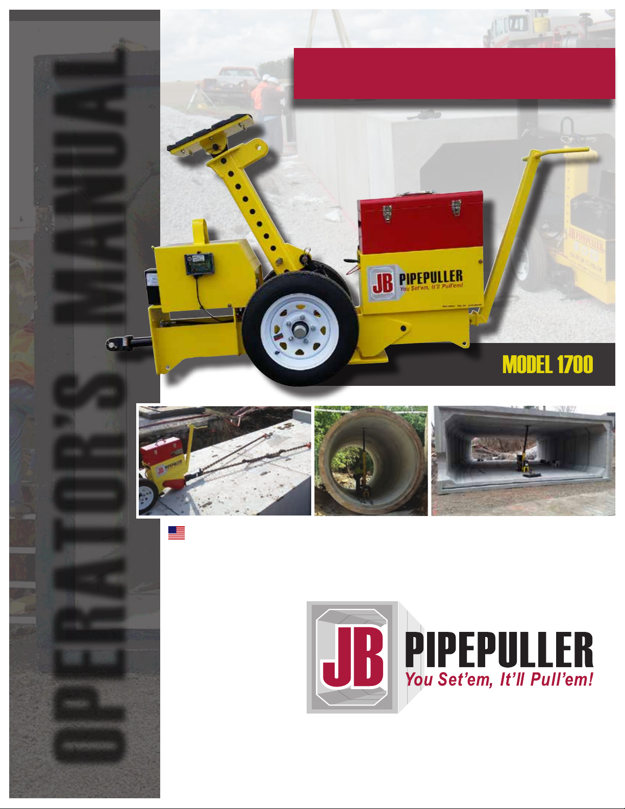
The New Generation of Pipe Pullers
MODEL 1700
MADE IN THE USA
OPERATOR’S MANUAL
Revised Addition 02 - October 2017
Page 2
TABLE OF CONTENTS
INTRODUCTION ..................................................................................................2
OPERATOR’S MANUEL
SPECIFICATIONS / FEATURES
GENERAL CONSIDERATIONS
SAFETY
...............................................................................................................5
PARTS DESCRIPTION
OPERATION
....................................................................................................... 11
MAINTENANCE
J-HOOK DIAGRAMS
.......................................................................................9
................................................................................................ 19
....................................................................................... 20
POST ADJUSTMENT CHARTS
J-LINK DIAGRAMS
TROUBLESHOOTING
LIMITED WARRANTY
NOTES
.............................................................................................................. 30
........................................................................................24
........................................................................................ 26
.................................................................................... 29
......................................................................3
.......................................................................... 4
....................................................................... 21
JB Pipepuller l Table of Contents
1
Page 3

INTRODUCTION
It is the responsibility of the owner and operators of this equipment to
read and understand the information contained in this manual. Improper
use due to failure to follow safety guidelines and become familiar with the
pipepuller could result in serious injury or death. The information in this
manual will cover important safety tips, recommended maintenance, and
other general information. Following these recommendations will provide
the operator with safe, efcient use of this equipment. Keep this manual in
a safe place for future reference. In the event your JB Pipepuller changes ownership, this manual MUST accompany the machine. Additional
manuals are available by contacting Basinger Manufacturing.
To ensure your JB Pipepuller remains in top working condition, it requires
general maintenance. General cleaning as well as routine maintenance
is necessary and will be highlighted in this manual. Safety messages and
decals are located on the pipepuller as well as in this manual. It is the oper-
ator’s responsibility to read and follow these safety messages.
In the event replacement parts are needed, contact Basinger Manufacturing. Using unapproved replacement parts will void the warranty and
could compromise the safe operation of your equipment.
2
Upon receiving your pipepuller, use the space below to record information for future reference.
Contact Information
Jon Basinger, President/CEO
Basinger Manufacturing, LLC
4080 E. Hook Waltz Rd.
Elida, OH 45807
Phone: (419) 296-5040
E-Mail: [email protected]
Date of Purchase: ______________________________________
Model: ________________________________________________
Serial Number: _________________________________________
Introduction l JB Pipepuller
Page 4

JB PIPEPULLER SPECIFICATIONS
MODEL 1600
Weight 690 lbs.
Height 43 inches
Length 71 inches
Width 24 inches
PSI 3000 pounds
Hydraulic Oil Capacity 9 quart
Pulling Force 15.5 tons
Battery 12 Volt Deep Cycle
(1450 Cold Cranking Amps)
FEATURES
n Self- releasing Strut — Hydraulic Release System (Patented)
n Extendable Strut Up to 14 Feet — 24” Stackable Extensions
n Solid Pull J-Link system — Eliminate Chains and Cables
n Cordless Remote — Reception Good for 150’
n Voltage Meter — Keep Track of the Voltage in the Battery
n Shut Off Switch
n Steel Pallet — Used to Store All Parts on and Shipping
n Three Sizes of J-Hooks — Used to Hook onto Boxes
n Laser Friendly — Pipe Puller Design Allows Laser to Shoot thru Lower Shoe
n Adjustable Wheels — Allows for Perfect Fit in Round Pipe
JB Pipepuller l Specifications l Features
3
Page 5
GENERAL CONSIDERATIONS
n In order to show detailed parts of the pipepuller, some photographs
may be shown without proper safety equipment in place.
NEVER operate the machine without proper safety equipment
in place. NEVER alter or modify the safety equipment.
n It is the responsibility of the owner and operators to thoroughly read
and understand this manual.
n The instructions in this manual are meant to provide guidance as you
become familiar with your pipepuller. As the operators gain familiarity
with this machine, he/she can develop operations specic to their
operating environment.
n Basinger Manufacturing may make periodic updates to the design
or construction of the JB Pipepuller. These updates may cause
a slight variation in design and/or construction.
n Directional identiers including left, right, front, rear, top, bottom, etc.
are made assuming the operator is positioned facing the hydraulic
valve selector.
n Proper shoring and safety precautions must be in place
when working below grade.
4
General Considerations l JB Pipepuller
Page 6
SAFETY
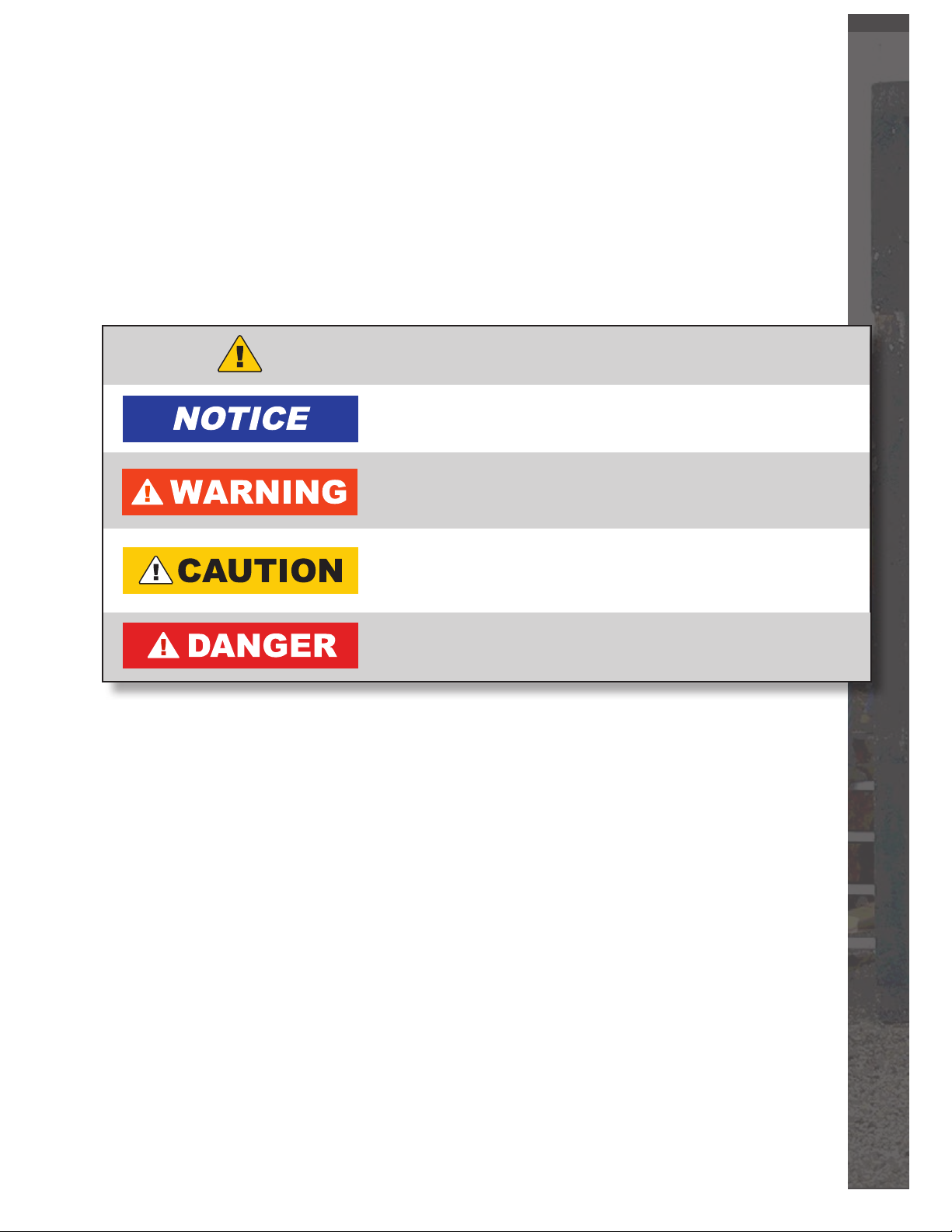
This manual contains safety messages designed to alert the user to
exercise caution in certain situations. Take a moment to review the safety
symbols and their meanings below.
This safety alert symbol is used to alert the operator of physical
injury hazards. Read the warnings to avoid risking injury or death.
This symbol marks a recommended practice to directly
or indirectly avoid personal injury or property damage.
If not avoided, the scenario could result in minor or moderate
personal injury. This is also used to alert the user of unsafe
practices.
If not avoided, the scenario could result in death or serious injury.
This warning presents a lesser degree of injury than those labeled
with DANGER.
If not avoided, the scenario will result in death or serious injury.
This indicates the most extreme circumstances.
JB Pipepuller l Safety
5
Page 7
SAFETY Continued
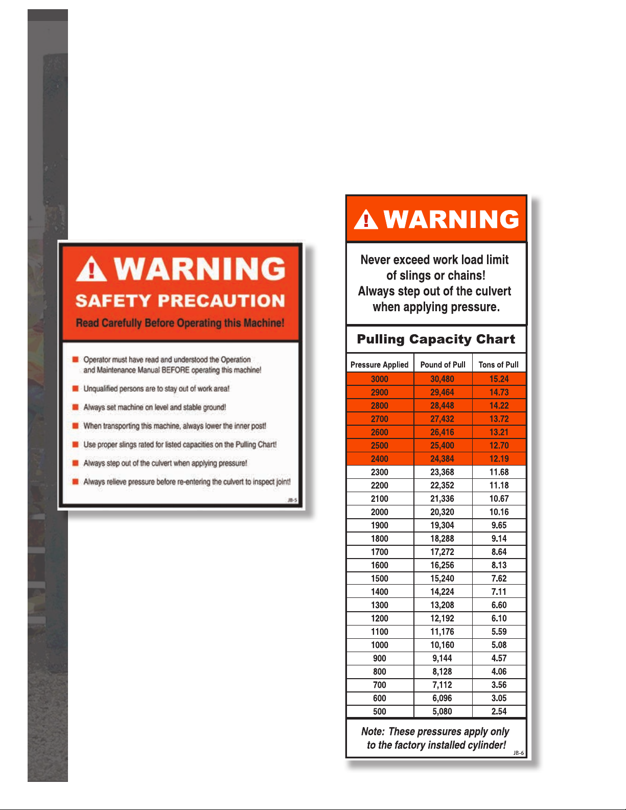
Safety Warning Decals
The following safety warning decals located on the JB Pipepuller
indicate a potential for personal injury if appropriate precautions are
not taken. It is the operator’s responsibility to review all safety and
operational information prior to operating the JB Pipepuller.
6
Safety l JB Pipepuller
Page 8
Training
n Failure to follow the safety instructions in this manual could result
in severe personal injury or death as well as damage to personal
property. Keep in mind the safety instructions found in this manual
are not all inclusive. The operator must exercise common sense
and practice safe operations while using this equipment.
n Should questions regarding this manual arise,
contact Basinger Manufacturing.
n All operators of this equipment should actively practice the following:
n
Be familiar with operating the controls while running the machine.
n
Be familiar with emergency shutdown procedures.
n
Always provide new operators with appropriate training.
NEVER allow an inexperienced person to operate the machine
without proper training.
n
ALWAYS take necessary precautions to protect yourself
from pressurized hydraulic uid. Use a rag, cardboard, etc.
to check a connection for leaks—NEVER use your hand or other
body part. Always wear appropriate eye protection, clothing,
and footwear.
n
Unqualied individuals are to never operate this equipment.
Basinger Manufacturing has designed and manufactured this equipment
with safety and efciency in mind. It is important to remember that safety ulti-
mately lies in the hands of a procient and safety-minded equipment operator!
Use extreme caution while operating in open trenches. Proper shoring
is required prior to beginning work.
In the event hydraulic uid contacts your eyes or punctures your skin, you
must immediately seek medical treatment by a physician. Even the smallest
wound is considered a serious injury and will result in serious injury or death
if not treated immediately.
JB Pipepuller l Safety
7
Page 9
SAFETY Continued
Pre-Work Safety Review
Use this safety review as a checklist to refresh yourself with safe operating
guidelines. This checklist is not all-inclusive and should include additional condi-
tion-specic considerations based on the operator’s experience.
n The operator must read and understand this operator’s manual before operating
the JB Pipepuller.
n Unqualied persons are to remain clear of the work area.
n Always place the pipepuller on level and stable ground.
n When transporting this machine, always lower the inner post and lock
the wheels in place.
n Use proper slings rated for the listed capacities on the pulling chart.
n Always step out of the culvert when applying pressure.
n Always relieve pressure before re-entering the culvert to inspect the joint.
n Wear appropriate personal safety equipment including, but not limited to,
hardhat, safety-toe footwear, hearing protection, safety glasses and gloves.
Cover exposed skin while working on/operating the equipment. Avoid loose
clothing, jewelry, hair, or anything that could become tangled in moving equipment.
n Purge the air from the hydraulic system by actuating hydraulic controls until all air
is removed from the system. This procedure must be performed any time
a hydraulic hose is disconnected and prior to initial service. Take extra caution
to prevent dirt and debris from contaminating the hydraulic uid reservoir
as this may cause failure of the hydraulic system.
n Function check all controls to ensure they match the appropriate operation
of the machine as indicated in this manual.
n Replace hoses or sleeves if damaged or if protective sleeve cannot be properly
positioned or secured.
n All hydraulic hoses, ttings, and valves must be in proper working condition.
Inspect for abrasions, cuts, kinks, excessive wear, and sharp angles
in hydraulic hoses.
n Inspect safety warning decals. If they are missing or not legible, replace them.
n Ensure all safety guards are in place and in good repair. If needed, replace them.
n Other condition-specic safety procedures as deemed necessary by an experienced
operator.
n Be aware of overhead obstructions including power lines and dead branches.
n NEVER operate ANY kind of equipment while under the inuence of drugs or alcohol.
n Always use equipment during the day or with sufcient supplemental lighting.
8
n ALWAYS know what’s below. Dial 811 if working near public utilities and pipelines.
Safety l JB Pipepuller
Page 10
10’ Tall
8’ Tall
6’ Tall
4’ Tall
Upper Shoe
Inner Post
Strut Extensions
Standard Strut
Selector Valve
Power Unit
Pull Cylinder
Key Link
Short Link
J-Hook
Medium J-Link
Long J-Link
Lower Shoe
Battery
Strut Cylinder
Lift Here
Medium J-Link
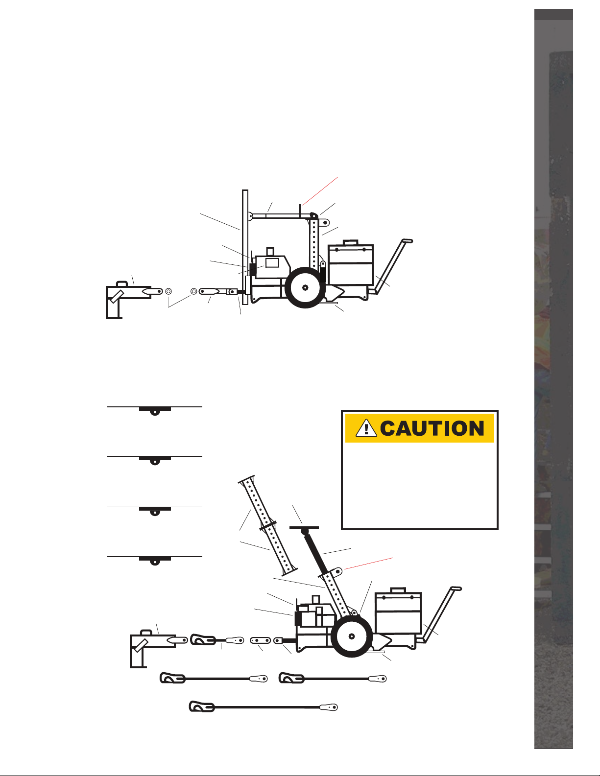
PARTS DESCRIPTION
Short Post
Selector Valve
Power Unit
Pull Cylinder
Pull Clevis
J-Hook
Lower Shoe
Battery
Lift Here
Outer Post Strut
Remote Receiver
Bushings
Front Mount Tube
Front Mount
Stabilizer
JB Pipepuller with Front Mount Tube
(Used on Culverts 4’ Tall and Shorter)
JB Pipepuller Base Unit
(Used on Reinforced Concrete Culverts 4’-10’ Tall)
n
Always bolt heavy duty strut
extentions first to lower strut.
n
ALL Strut Extensions must be
bolted on with grade 8 bolts,
nuts and lock washers.
Torque at 100 ft. lbs.
JB Pipepuller l Parts Description
9
Page 11
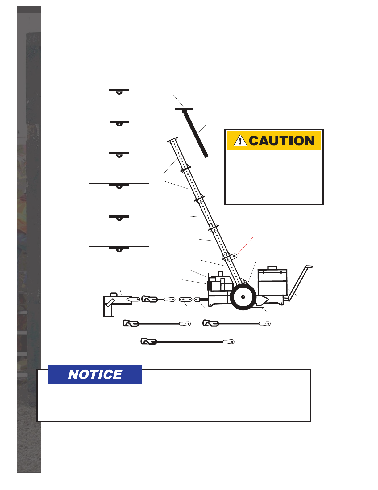
14’ Tall
12’ Tall
10’ Tall
8’ Tall
6’ Tall
4’ Tall
Upper Shoe
Inner Post
Strut Extensions
Heavy Duty
Strut Extension
Heavy Duty Strut
Selector Valve
Power Unit
Pull Cylinder
Key LinkShort Link
J-Hook
Medium J-Link
Long J-Link
Lower Shoe
Battery
Strut Cylinder
Lift Here
Medium J-Link
Heavy Duty
Strut Extension
PARTS DESCRIPTION Continued
JB Pipepuller Base Unit with Heavy Duty Strut
(Used on Reinforced Concrete Culverts 4’-14’ Tall)
n
Always bolt heavy duty strut
extentions first to lower strut.
n
ALL Strut Extensions must be
bolted on with grade 8 bolts,
nuts and lock washers.
Torque at 100 ft. lbs.
This parts diagram shows the optional heavy duty strut and strut extension.
If you are pulling pipe 10 feet or more in inside height, the heavy duty strut
and strut extension are required.
10
Parts Description l JB Pipepuller
Page 12
OPERATION
Setting up the JB Pipepuller
The following steps will outline the steps necessary to set up the
JB Pipepuller to pull reinforced concrete pipe. For additional instruction,
a detailed training video is also available at www.jbpipepuller.com.
Important!
The wheel adjustment procedure should be followed depending on the
type of pipe you will be working with.
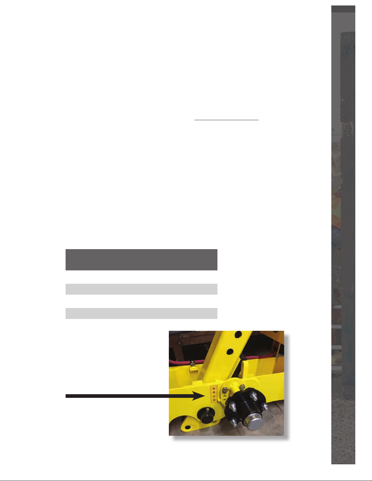
Wheel Adjustment Procedure
While the pipe puller is mounted on the pallet or supported by other
means, with the weight off of the wheels—
Remove the two half inch bolts and loosen the center bottom bolt. Raise
or lower the wheel to the proper setting then re-insert the two bolts to the
new setting and tighten all three bolts. Torque bolts at 100 ft. lbs.
This procedure is required for both wheels.
Setting Inside Height Pipe Type
of Culvert
A 48” Round
B 54”-66” Round
C 72”-84” Round
D 96” Flat Bottom Box
Shown here is an example
of the wheel adjustment settings
with the wheel removed.
JB Pipepuller l Operation
11
Page 13
OPERATION Continued
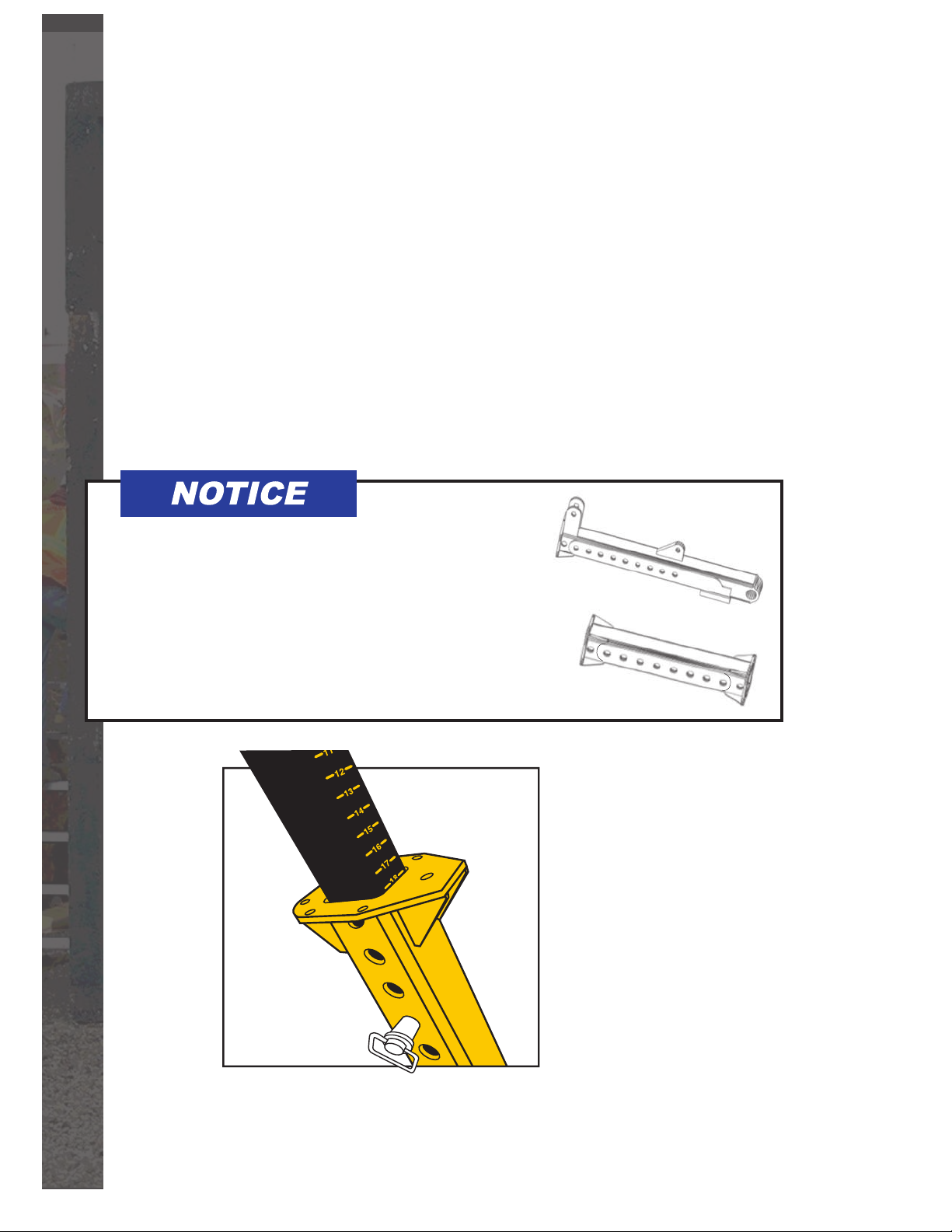
STEP 1: Setting the Post Height
n Measure the inside height of the culvert and record the measurement.
n Use the post adjustment chart located on the side of the power unit
cover to determine the appropriate post setting.
n Slide either the long or short post into the outer post strut
with the numbers facing the tool box end of the pipepuller.
n Set the post to the proper setting and insert the 1” pin
into the matching hole.
Several examples using the post adjustment chart are located
on the next page.
If you are going to be pulling pipe with an inside
height greater than 10 feet, you are required to
use the heavy duty strut and heavy duty strut extensions. These specialized strut and extensions
provide greater stability for the increased height
of boxes over 10 feet. Contact JB Manufacturing
about the use of these struts if you have questions.
12
Operation l JB Pipepuller
Page 14
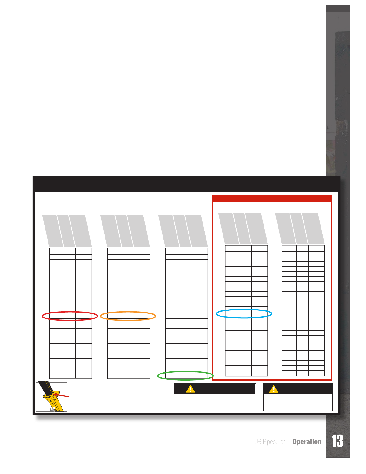
Post Adjustment Chart Examples
Example #1: Culvert height of 60”, select the inner post
and set to number 14.5.
Example #2: Culvert height of 84”, install strut extension, then insert
inner post and set to number 15.
Example #3: Culvert height of 120”, install 2 strut extensions
then inner post and set to 27.5.
Example #4: Culvert height of 132”, install 1 heavy duty strut extension
then 2 strut extensions and insert inner post and set to 15.
No Strut Extention
Inside Height of Culvert
Inside Height of Culvert
in Millimeters
in Inches
Adjust Post to this Height
in Inches
Post Adjustment Chart
1 Strut Extention
Inside Height of Culvert
Inside Height of Culvert
in Millimeters
in Inches
Adjust Post to this Height
in Inches
2 Strut Extentions
Inside Height of Culvert
Inside Height of Culvert
in Millimeters
in Inches
Adjust Post to this Height
in Inches
Used with the Heavy Duty Strut Option Only
2 Strut Extentions AND
1 Heavy Duty Stut Extention
Inside Height of Culvert
in Inches
Inside Height of Culvert
in Millimeters
Adjust Post to this Height
in Inches
2 Strut Extentions AND
2 Heavy Duty Stut Extentions
Inside Height of Culvert
in Inches
Inside Height of Culvert
in Millimeters
Adjust Post to this Height
in Inches
Inches MM Setting
48
4’
5’
6’
1219
49
1245
50
1270
51
1295
52
1321
53
1346
54
1372
55
1397
56
1422
57
1448
58
1473
59
1500
60
1524
61
1549
62
1575
63
1600
64
1626
65
1651
66
1676
67
1702
68
1727
69
1753
70
1778
71
1800
72
1829
Inches MM Setting
2
3
4
5
6
7
8
9 1/2
10 1/2
11 1/2
12 1/2
13 1/2
14 1/2
15 1/2
16 1/2
18
19
20
21
22
23
24
25
26 1/2
27 1/2
72
6’
73
74
75
76
77
78
79
80
81
82
83
84
7’
85
86
87
88
89
90
91
92
93
94
95
96
8’
1829
1854
1880
1905
1930
1956
1981
2007
2032
2057
2083
2100
2134
2159
2184
2210
2235
2261
2286
2311
2337
2362
2388
2400
2438
2
3
4 1/2
5 1/2
6 1/2
7 1/2
8 1/2
9 1/2
10 1/2
12
13
14
15
16
17
18
19
20
21 1/2
22 1/2
23 1/2
24 1/2
25 1/2
26 1/2
27 1/2
Refer to the Pre-measured Guide on the Inner Post
for easy preset. The numbers are on the BACKSIDE
of the Inner Post and are to be lined up
on the TOP REAR EDGE of the Outer Post.
Inches MM Setting
96
8’
97
98
99
100
101
102
103
104
105
106
107
108
9’
109
110
111
112
113
114
115
116
117
118
119
120
10’
2438
2464
2489
2515
2540
2565
2591
2616
2642
2667
2692
2700
2743
2769
2794
2819
2845
2870
2896
2921
2946
2972
3000
3023
3048
2
3
4
5
6
7
8 1/2
9 1/2
10 1/2
11 1/2
12 1/2
13 1/2
15
15 1/2
16 1/2
18
19
20
21
22
23
24
25
26 1/2
27 1/2
CAUTION
■ Always bolt heavy duty strut extentions first to lower strut.
■ ALL Strut Extensions must be bolted on with grade 8 bolts,
nuts and lock washers. Torque at 100 ft. lbs.
Inches MM Setting
120
10’
11’
12’
3048
121
3073
122
3099
123
3124
124
3150
125
3175
126
3200
127
3226
128
3251
129
3277
130
3302
131
3327
132
3353
133
3378
134
3404
135
3429
136
3454
137
3480
138
3505
139
3531
140
3556
141
3581
142
3607
143
3632
144
3658
Inches MM Setting
144
3658
145
3683
146
3708
147
3724
148
3759
149
3785
150
3810
151
3835
152
3861
153
3886
154
3912
155
3937
156
3962
157
3988
158
4013
159
4039
160
4064
161
4089
162
4115
163
4140
164
4166
165
4191
166
4216
167
4242
168
4267
8 1/2
9 1/2
10 1/2
11 1/2
12 1/2
13 1/2
15
15 1/2
16 1/2
18
19
20
21
22
23
24
25
26 1/2
27 1/2
2
3
4
5
6
7
12’
13’
14’
CAUTION
■ Always follow the chart recommendations.
■ Decreasing the post length could cause damage
to the culvert.
2
3
4
5
6
7
8 1/2
9 1/2
10 1/2
11 1/2
12 1/2
13 1/2
15
15 1/2
16 1/2
18
19
20
21
22
23
24
25
26 1/2
27 1/2
JB-7
JB Pipepuller l Operation
13
Page 15
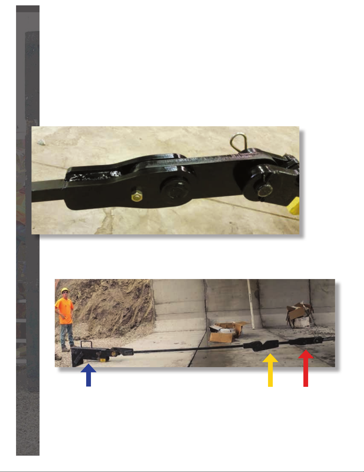
OPERATION Continued
STEP 2: J-Link & J-Hook Selection
Next you need to select the proper length J-Link. Refer to the J-Link page
for proper selection. There is also a J-Hook reference sheet in this manual.
The idea behind this step is to only take the necessary J-Link and J-Hook
components with you into the culvert. Also, it is easier to ensure the key
link is installed on the end of the pulling cylinder before placing the puller
into the culvert.
Shown above is the key link which attaches to the pulling cylinder
on the right and a J-Link section on the left.
The blue arrow points to a properly placed J-Hook.
Note the yellow shim under the back of the hook
to maintain parallel pulling force.
The yellow arrow shows the short J-Link
positioned with the hook opening facing up.
The red arrow indicates the key link.
14
Operation l JB Pipepuller
Page 16
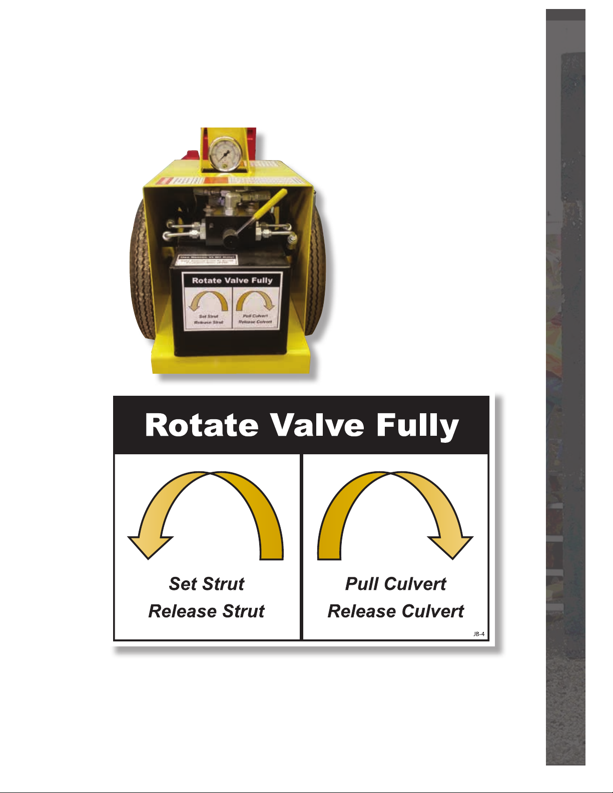
Step 3: Cylinder Selector Valve Operation
After setting the valve to the left or the right, activate the remote.
JB Pipepuller l Operation
15
Page 17
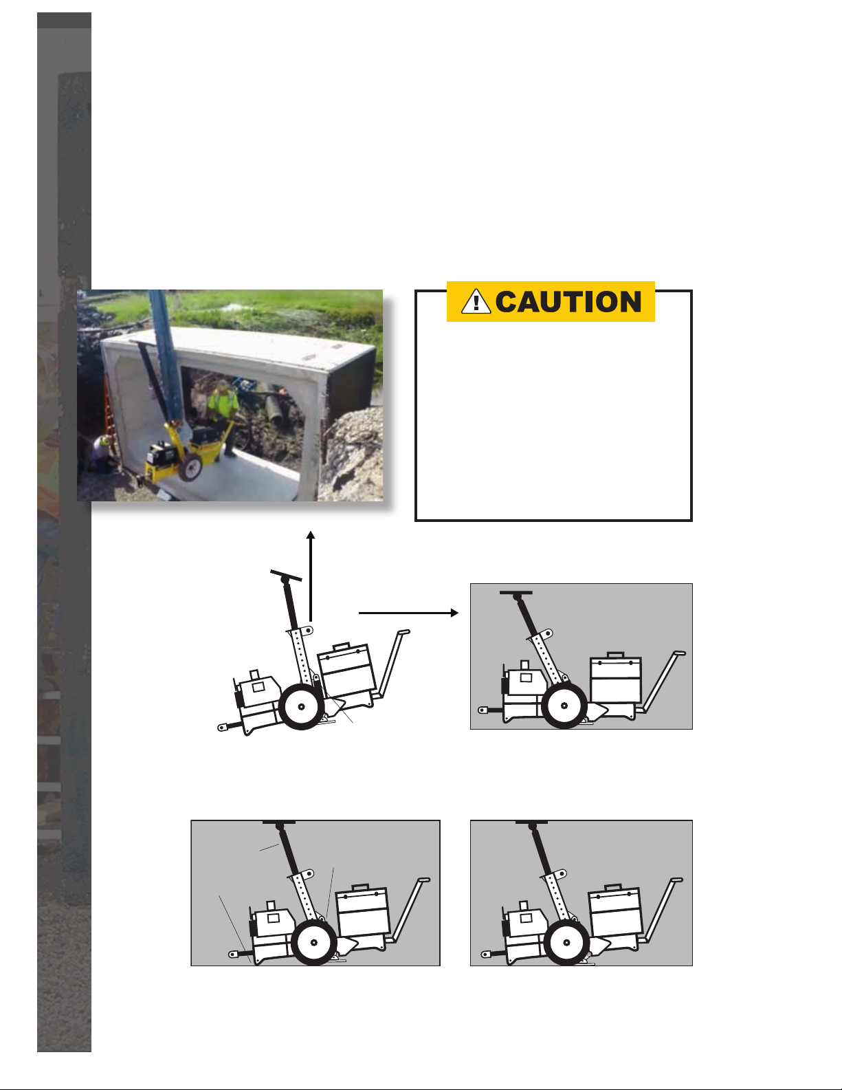
OPERATION Continued
STEP 4: Lower Puller into Culvert
The lower shoe must be in the up position before placing the pipepuller
into the culvert. With the pipepuller in transport position, connect a properly
sized sling to the lifting ears and gently lower the pipepuller into the culvert
facing the direction the culverts are to be pulled. Use the handlebars to
guide the pipepuller into the culvert as it is being lowered.
NEVER for ANY reason
place yourself or any body
part under any object be-
ing lifted overhead. Doing so
risks serious injury or death!
Crane controls and hydraulic
systems can fail even when
the equipment is not running!
In Position to Set
Push Strut
into ceiling
and activate
hydraulics
Tip Front End to Floor
Pull into Culvert
Cylinder Closed
Cylinder needs to be closed
before setting the strut
to ceiling
Transport Position
Set and Ready to Pull
Fully extend the strut cylinder
when setting the Strut.
16
Operation l JB Pipepuller
Page 18
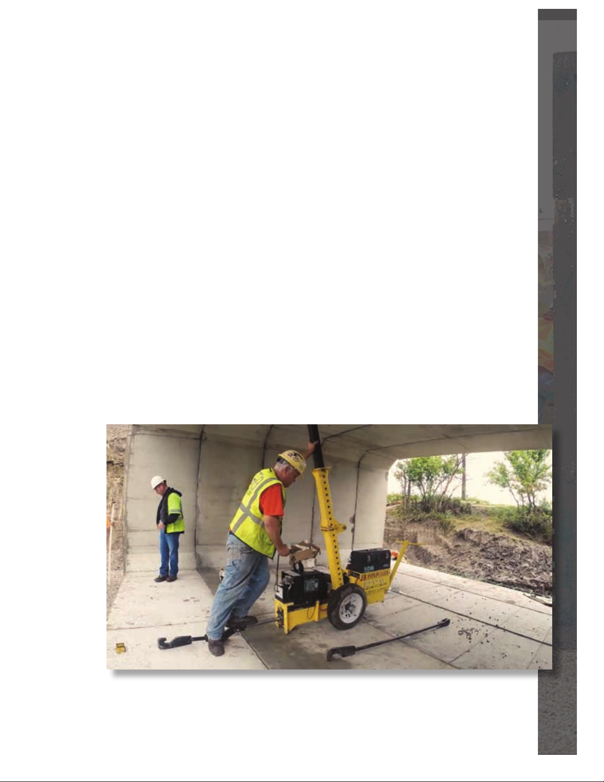
Step 5: Set up J-Links and Lock Puller in Position
n Position the JB Pipepuller in the direct line of pull and lay out the J-link
and J-hook so they are in line with the direction of pull.
n Position the J-hook on the culvert. Note that the J-Hook may require shims
to keep the pulling force parallel to the culvert. See the J-Hook section
of the manual for more important details.
n Attach the proper length J-Link to the key link on the pulling cylinder.
n With the selector valve rotated to the left, tip the front of the puller
to the oor, shove the strut to the ceiling, then activate the remote.
n This will rotate the shoe to the oor and lock the puller into position,
ready to pull. Remember, the cylinder needs to be fully extended
when setting the Strut.
n Now extend the pulling cylinder and hook the J-Link onto the J-Hook
and position the selector valve to the right and activate the remote
to pull the rst culvert into place.
n At full pull, the cylinder has 15.5 tons of pulling power.
n Remember, stand off to one side at the edge of the culvert
for safety purposes.
This picture shows the procedure for locking the puller into place prior to pulling.
JB Pipepuller l Operation
17
Page 19
OPERATION Continued
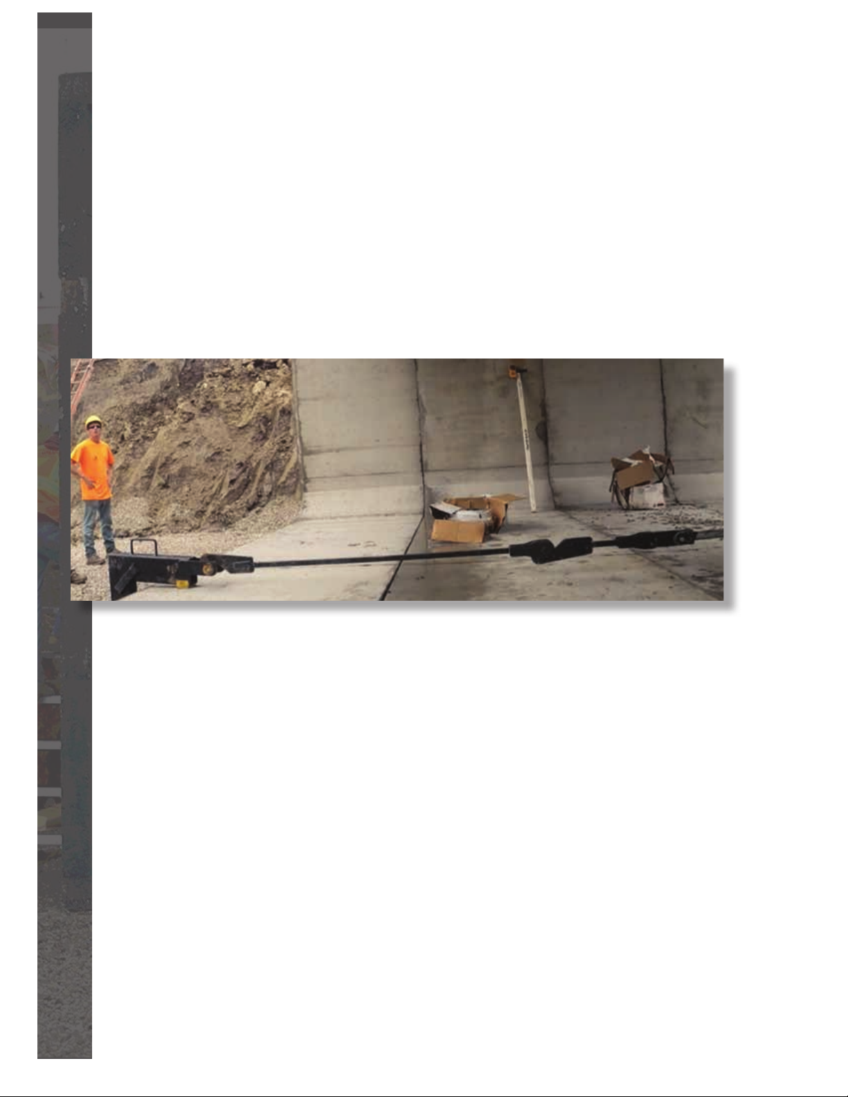
STEP 6: Attach 2nd J-Link
n After pulling the rst culvert, you may need to attach the 2nd J-Link
to keep one culvert between the puller and the culvert being pulled,
as shown in the picture below.
n After the rst culvert is seated, release it by activating the remote.
n Switch the Valve Selector to the left, and support the strut with your hand.
Activate the remote- this will un-wedge the strut.
n Reposition the puller and extend the pulling cylinder so after you add
the 2nd J-Link, it drops over the J-Hook as you retract the pulling cylinder.
18
STEP 7: Release Pipepuller and Reposition
n After the culvert is seated, release the culvert by activating the remote.
n Switch the Valve Selector to the left, and support the strut with your hand.
Activate the remote- this will un-wedge the strut.
n With the strut cylinder completely retracted, the JB Pipepuller is ready
to move forward. Repeat steps 5 & 6 until all culverts are set.
Operation l JB Pipepuller
Page 20
MAINTENANCE
Battery
The JB Pipepuller is powered by an Interstate SRM-4D deep cycle battery.
It has 1645 cranking amps and 1314 cold cranking amps. It is recommended that the battery be fully charged at the end of its daily use. It is recommended that the battery be charged at a slow rate, preferably in deep cycle
mode. An automatic charger is highly recommended. The water level in the
battery should be checked periodically. If taken care of properly, this battery
will give you many years of service.
Hydraulics
The JB Pipepuller is powered by a Monarch DC power unit capable
of putting out 3000 psi. The recommended oil for this unit is Dextron IV.
Before adding any oil, always have the cylinder in the closed position.
It is critical to ensure no dirt or debris is introduced into the system
while adding oil. Contaminated hydraulic oil can cause failure of the
hydraulic system.
JB Pipepuller l Maintenance
19
Page 21
J-HOOK DIAGRAMS
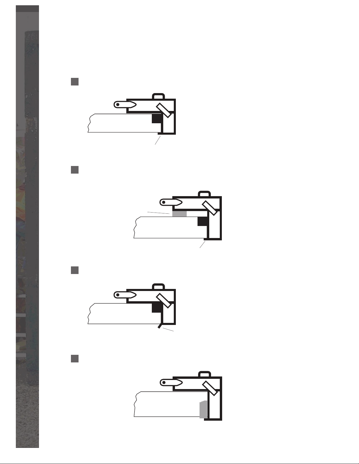
Example of using a J-Hook on an 8” culvert
Due to varying thickness of boxes,
Cross Section of an 8” Thick Pipe
Must be fully inserted
before pulling!
Example of using a larger J-Hook on a smaller culvert thickness
Shim must be used to prevent rotation of J-Hook!
Always us a solid shim to make up
the dierence in the culvert space!
Cross Section of an 10” Thick Pipe
the J-Hook measures 8 3/4” in depth.
Due to varying thickness of boxes,
the J-Hook measures 12 3/4” in depth.
Must be fully inserted
before pulling!
Example of what will Happen if pipe are thicker than the design of the J-Hook!
Due to varying thickness of boxes,
Cross section of an 8” thick pipe
that actually measures almost 9”.
the J-Hook measures 8 3/4” in depth.
If pipe is thicker than J-Hook
dimensions, this WILL HAPPEN!
Example of using a J-Hook installing pipe backward using a precut oak block no less than 18” long!
12” Thick Culvert
20
J-Hook Diagrams l JB Pipepuller
Page 22
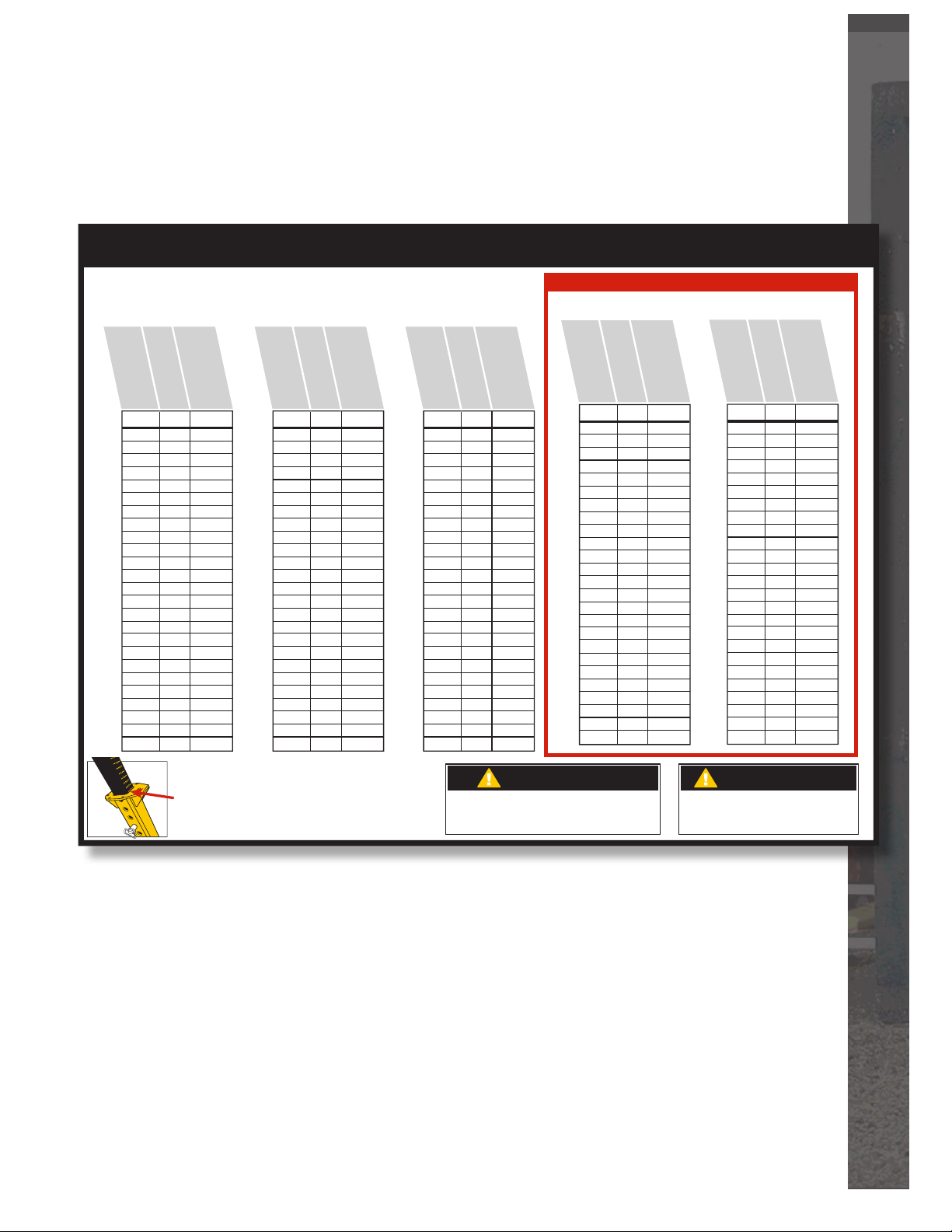
No Strut Extention
Inside Height of Culvert
Inside Height of Culvert
in Millimeters
in Inches
Adjust Post to this Height
in Inches
Post Adjustment Chart
1 Strut Extention
Inside Height of Culvert
Inside Height of Culvert
in Millimeters
in Inches
Adjust Post to this Height
in Inches
2 Strut Extentions
Inside Height of Culvert
Inside Height of Culvert
in Millimeters
in Inches
Adjust Post to this Height
in Inches
Used with the Heavy Duty Strut Option Only
2 Strut Extentions AND
1 Heavy Duty Stut Extention
Inside Height of Culvert
in Inches
Inside Height of Culvert
in Millimeters
Adjust Post to this Height
in Inches
2 Strut Extentions AND
2 Heavy Duty Stut Extentions
Inside Height of Culvert
in Inches
Inside Height of Culvert
in Millimeters
Adjust Post to this Height
in Inches
Inches MM Setting
48
4’
5’
6’
1219
49
1245
50
1270
51
1295
52
1321
53
1346
54
1372
55
1397
56
1422
57
1448
58
1473
59
1500
60
1524
61
1549
62
1575
63
1600
64
1626
65
1651
66
1676
67
1702
68
1727
69
1753
70
1778
71
1800
72
1829
Inches MM Setting
2
3
4
5
6
7
8
9 1/2
10 1/2
11 1/2
12 1/2
13 1/2
14 1/2
15 1/2
16 1/2
18
19
20
21
22
23
24
25
26 1/2
27 1/2
72
6’
73
74
75
76
77
78
79
80
81
82
83
84
7’
85
86
87
88
89
90
91
92
93
94
95
96
8’
1829
1854
1880
1905
1930
1956
1981
2007
2032
2057
2083
2100
2134
2159
2184
2210
2235
2261
2286
2311
2337
2362
2388
2400
2438
2
3
4 1/2
5 1/2
6 1/2
7 1/2
8 1/2
9 1/2
10 1/2
12
13
14
15
16
17
18
19
20
21 1/2
22 1/2
23 1/2
24 1/2
25 1/2
26 1/2
27 1/2
Refer to the Pre-measured Guide on the Inner Post
for easy preset. The numbers are on the BACKSIDE
of the Inner Post and are to be lined up
on the TOP REAR EDGE of the Outer Post.
Inches MM Setting
96
8’
97
98
99
100
101
102
103
104
105
106
107
108
9’
109
110
111
112
113
114
115
116
117
118
119
120
10’
2438
2464
2489
2515
2540
2565
2591
2616
2642
2667
2692
2700
2743
2769
2794
2819
2845
2870
2896
2921
2946
2972
3000
3023
3048
2
3
4
5
6
7
8 1/2
9 1/2
10 1/2
11 1/2
12 1/2
13 1/2
15
15 1/2
16 1/2
18
19
20
21
22
23
24
25
26 1/2
27 1/2
CAUTION
■ Always bolt heavy duty strut extentions first to lower strut.
■ ALL Strut Extensions must be bolted on with grade 8 bolts,
nuts and lock washers. Torque at 100 ft. lbs.
Inches MM Setting
120
10’
11’
12’
3048
121
3073
122
3099
123
3124
124
3150
125
3175
126
3200
127
3226
128
3251
129
3277
130
3302
131
3327
132
3353
133
3378
134
3404
135
3429
136
3454
137
3480
138
3505
139
3531
140
3556
141
3581
142
3607
143
3632
144
3658
Inches MM Setting
144
3658
145
3683
146
3708
147
3724
148
3759
149
3785
150
3810
151
3835
152
3861
153
3886
154
3912
155
3937
156
3962
157
3988
158
4013
159
4039
160
4064
161
4089
162
4115
163
4140
164
4166
165
4191
166
4216
167
4242
168
4267
8 1/2
9 1/2
10 1/2
11 1/2
12 1/2
13 1/2
15
15 1/2
16 1/2
18
19
20
21
22
23
24
25
26 1/2
27 1/2
2
3
4
5
6
7
12’
13’
14’
CAUTION
■ Always follow the chart recommendations.
■ Decreasing the post length could cause damage
to the culvert.
2
3
4
5
6
7
8 1/2
9 1/2
10 1/2
11 1/2
12 1/2
13 1/2
15
15 1/2
16 1/2
18
19
20
21
22
23
24
25
26 1/2
27 1/2
JB-7
JB Pipepuller l Post Adjustment Charts
21
Page 23
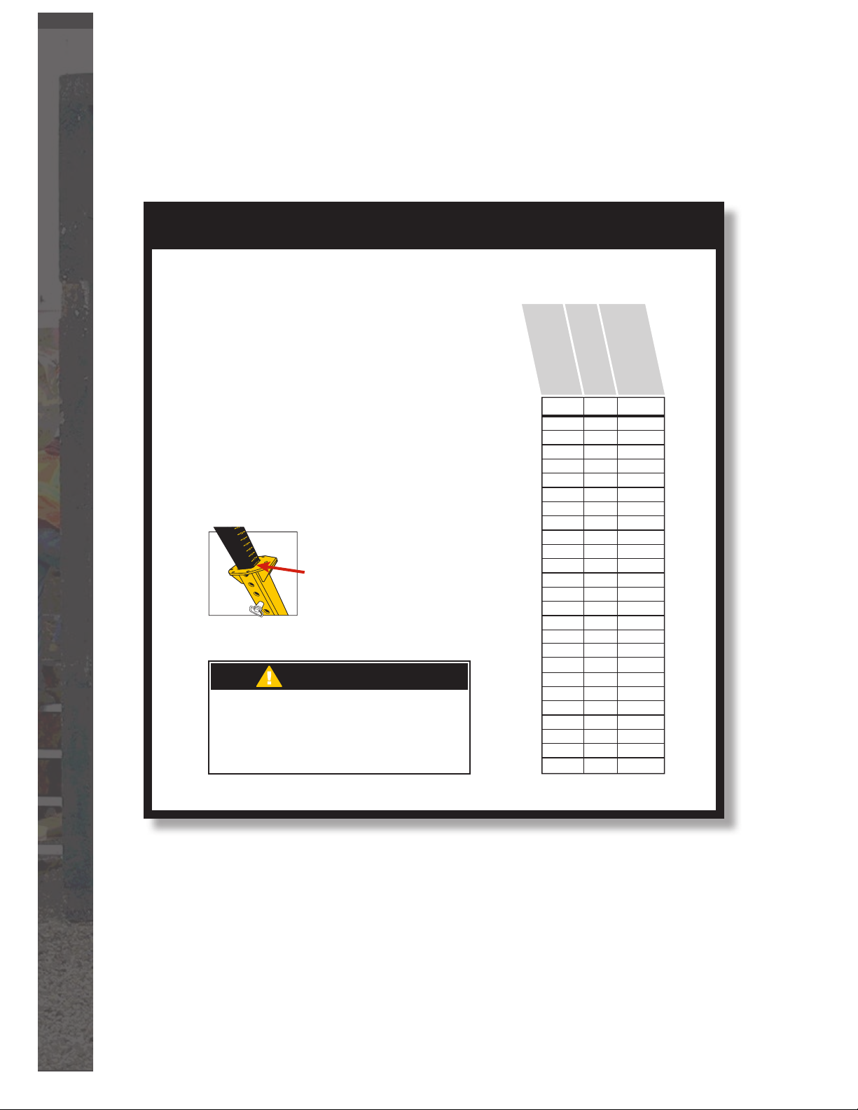
Post Adjustment Chart
2 Strut Extentions AND
1 Heavy Duty Stut Extention
Using Strut Extensions
(10’-12’)
For any culvert over 120” tall,
use Heavy Duty Strut Extention
bolted rst to the Lower Strut.
On top of Heavy Duty Strut bolt
the Regular Strut Extension
Refer to the Pre-measured Guide
on the Inner Post for easy preset.
The numbers are on the BACKSIDE
of the Inner Post and are to be lined
up on the TOP REAR EDGE
of the Outer Post.
CAUTION
■ Always follow the chart recommendations.
■ Decreasing the post length could cause damage to the culvert.
■ Always bolt heavy duty strut extentions first to lower strut.
■ ALL Strut Extensions must be bolted on with grade 8 bolts,
nuts and lock washers. Torque at 100 ft. lbs.
Inside Height of Culvert
in Inches
Inches MM Setting
120
10’
121
122
123
124
125
126
127
128
129
130
131
132
11’
133
134
135
136
137
138
139
140
141
142
143
144
12’
Inside Height of Culvert
in Millimeters
3048
3073
3099
3124
3150
3175
3200
3226
3251
3277
3302
3327
3353
3378
3404
3429
3454
3480
3505
3531
3556
3581
3607
3632
3658
Adjust Post to this Height
in Inches
2
3
4
5
6
7
8 1/2
9 1/2
10 1/2
11 1/2
12 1/2
13 1/2
15
15 1/2
16 1/2
18
19
20
21
22
23
24
25
26 1/2
27 1/2
22
Post Adjustment Charts l JB Pipepuller
Page 24
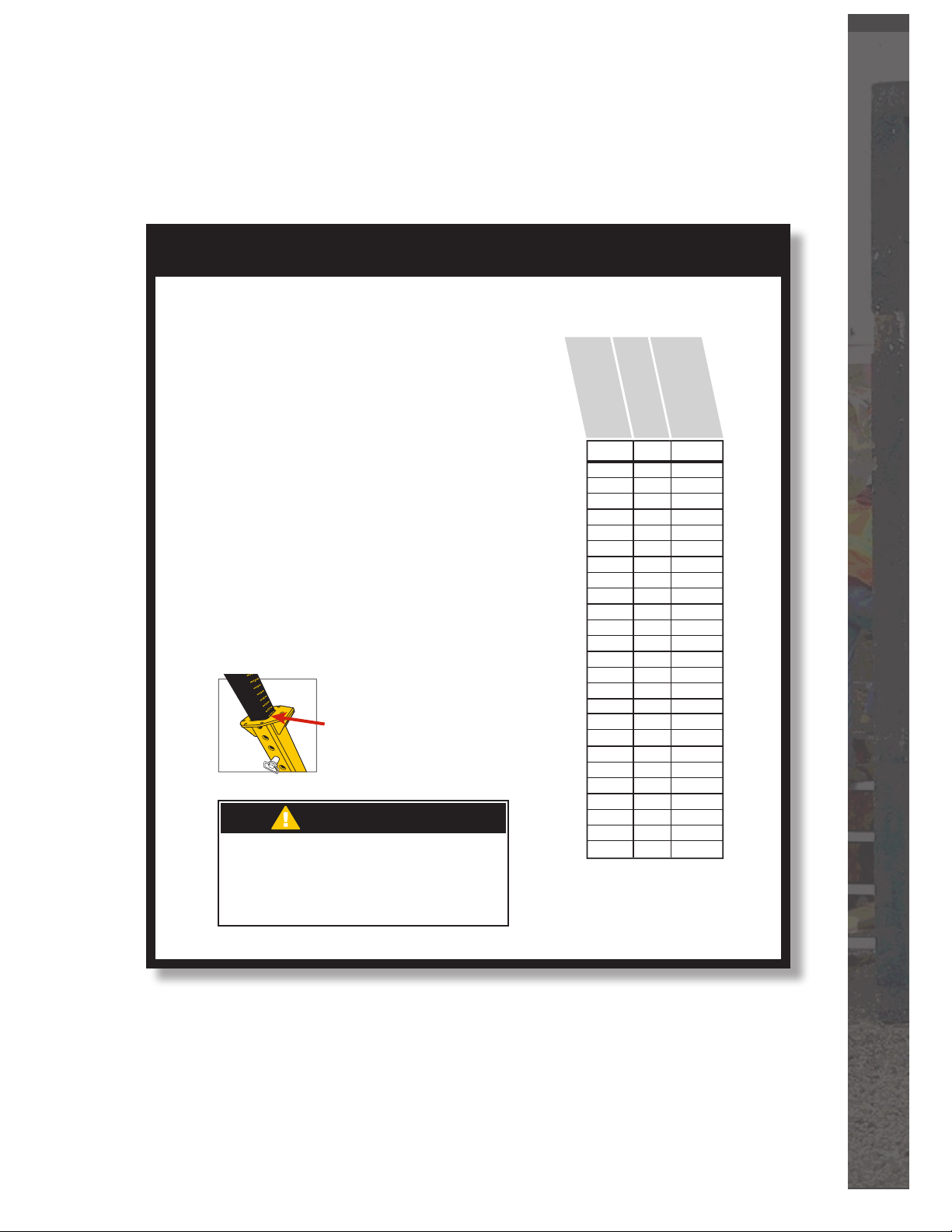
Post Adjustment Chart
2 Strut Extentions AND
2 Heavy Duty Stut Extentions
Using Strut Extensions
(12-14’)
For any culvert over 144” tall,
the Heavy Duty Strut MUST
be used.
Heavy Duty Strut Extention
bolted rst to the Lower
Heavy Duty Strut.
On top of Heavy Duty Strut
Extension bolt two Regular
Strut Extensions.
Refer to the Pre-measured Guide
on the Inner Post for easy preset.
The numbers are on the BACKSIDE
of the Inner Post and are to be lined
up on the TOP REAR EDGE
of the Outer Post.
CAUTION
■ Always follow the chart recommendations.
■ Decreasing the post length could cause damage to the culvert.
■ Always bolt heavy duty strut extentions first to lower strut.
■ ALL Strut Extensions must be bolted on with grade 8 bolts,
nuts and lock washers. Torque at 100 ft. lbs.
Inside Height of Culvert
in Inches
Inches MM Setting
144
12’
145
146
147
148
149
150
151
152
153
154
155
156
13’
157
158
159
160
161
162
163
164
165
166
167
168
14’
Inside Height of Culvert
in Millimeters
3658
3683
3708
3724
3759
3785
3810
3835
3861
3886
3912
3937
3962
3988
4013
4039
4064
4089
4115
4140
4166
4191
4216
4242
4267
Adjust Post to this Height
in Inches
2
3
4
5
6
7
8 1/2
9 1/2
10 1/2
11 1/2
12 1/2
13 1/2
15
15 1/2
16 1/2
18
19
20
21
22
23
24
25
26 1/2
27 1/2
JB Pipepuller l Post Adjustment Charts
23
Page 25
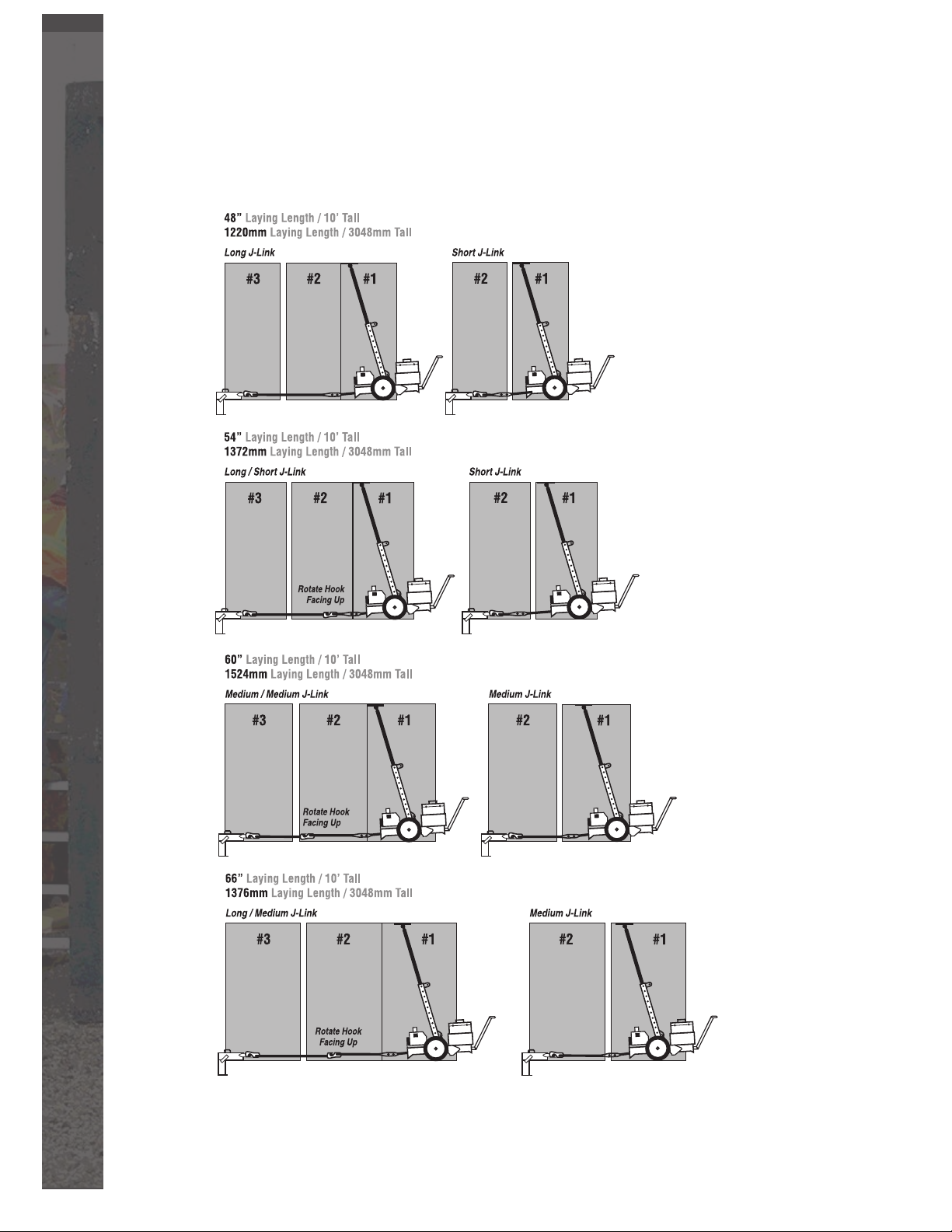
J-LINK DIAGRAMS
24
J-Link Diagrams l JB Pipepuller
Page 26
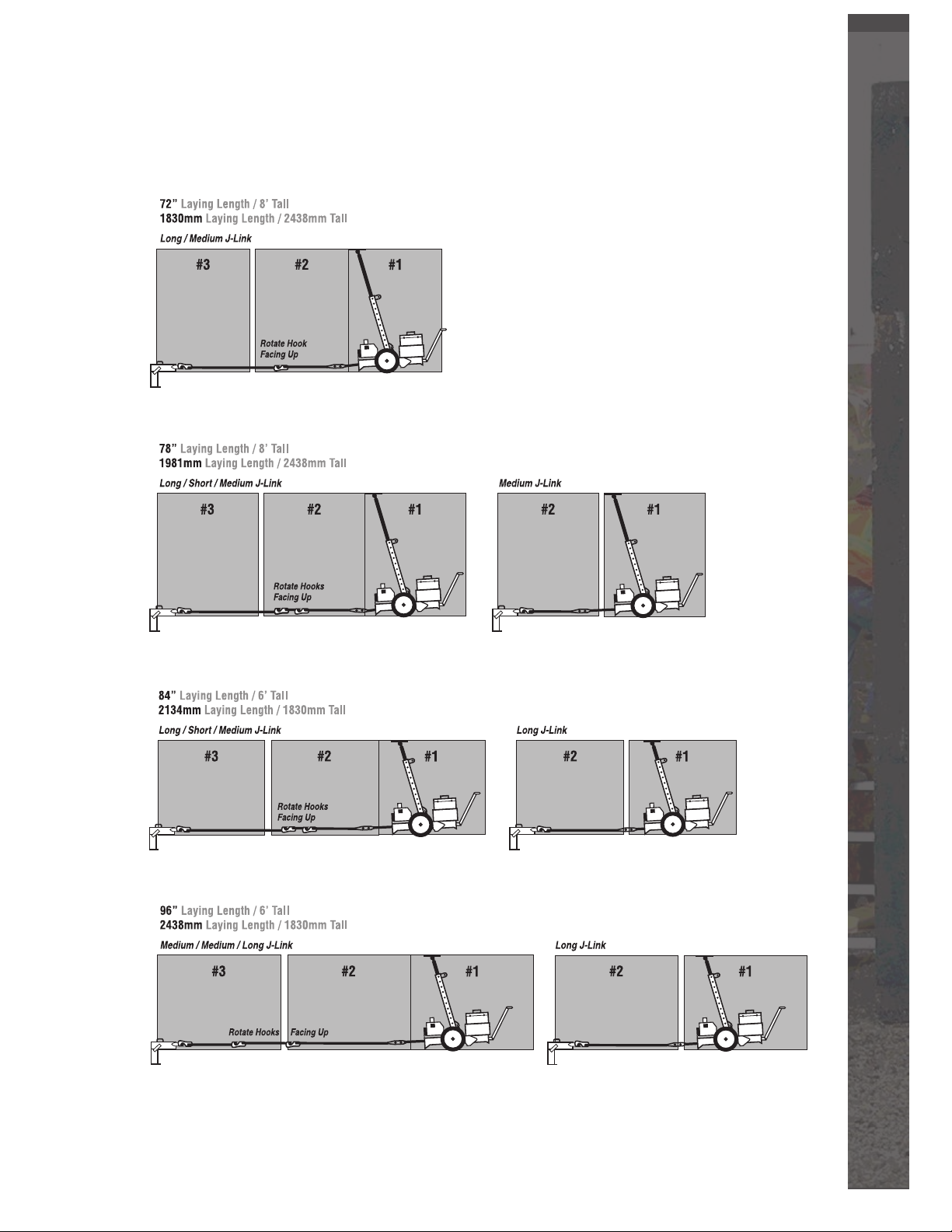
JB Pipepuller l J-Link Diagrams
25
Page 27
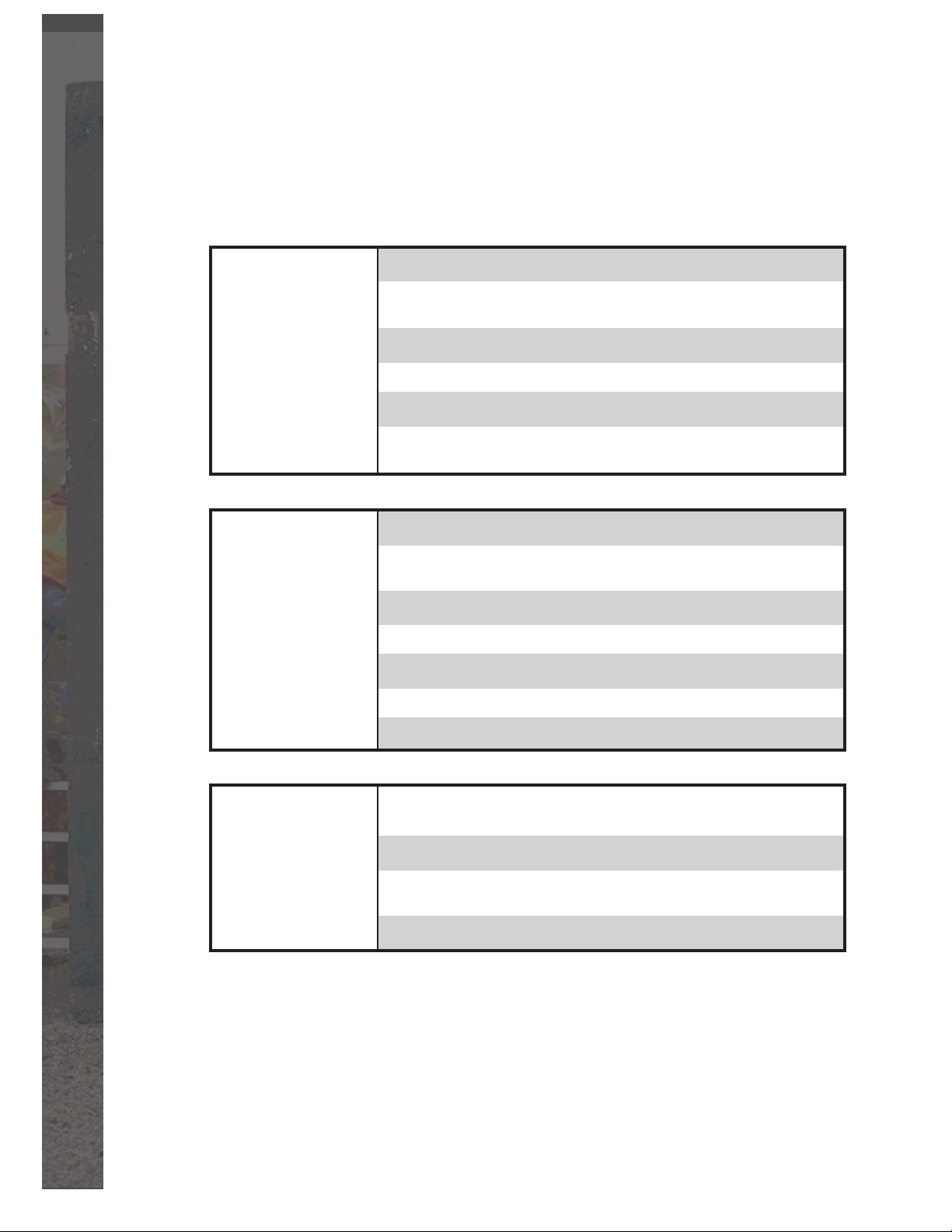
Troubleshooting
PROBLEM POSSIBLE CAUSE SOLUTION
Power unit will not run 12 volt Battery Low on charge Charge battery or replace
cord remote
10 amp fuse is blown Change fuse
Insufficient battery connection Clean and tighten battery connections
Improper Ground connection to frame Clean and tighten all connection points
for breaks
Cylinders will not operate 12 volt Battery Low on charge Charge battery or replace
Remote battery is low on charge Replace battery or use extension
cord remote
10 amp fuse is blown Change fuse
Insufficient battery connection Clean and tighten battery connections
Improper Ground connection to frame Clean and tighten all connection points
Hydraulic oil low Add oil
Hydraulic hose pinched or obstructed Change hose or clear obstruction
Remote battery is low on charge
Loose or broken wire
Check all connections and inspect wire
Replace battery or use extension
26
Strut does not set Improper post setting Refer to Post setting chart
for proper setting
Strut Cylinder is not fully extended Extend the cylinder to its full extension
Strut cylinder not closed before Retract cylinder before you shove the strut
engagment of ceiling to the cylinder
Improper wheel setting Read manual for proper setting
Troubleshooting l JB Pipepuller
Page 28
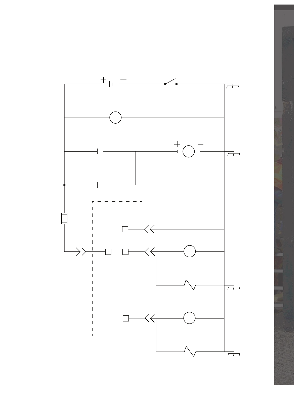
Cordless Remote Push Button
“LODAR” Model #110000
INTERSTATE
SRM-4D 12 Volt
Marine/RV
Deep Cycle Battery
Red
10
Volt Meter
Red
20
Solenoid Set
Red
30
Red
40
Blk
10 Amp
50
Standard
Blade Style
Fuse
Contact
Solenoid Release
Contact
V
Cordless Remote
“LODAR”
Model# 110000
Blk
Cole Hersee Master
Disconnect
(Minimum 11 Volts)
3
Chassis Ground
Hydraulic Motor
M
Set Solenoid
Blk
60
70
80
90
1
Red
Grn
F1
Yel
F2
Grn
4
Grn/Yel
Yel
2
Yel
S
Set Coil
Release Solenoid
S
Release Coil
Purple
Purple
30
40
JB Pipepuller l Troubleshooting
27
Page 29
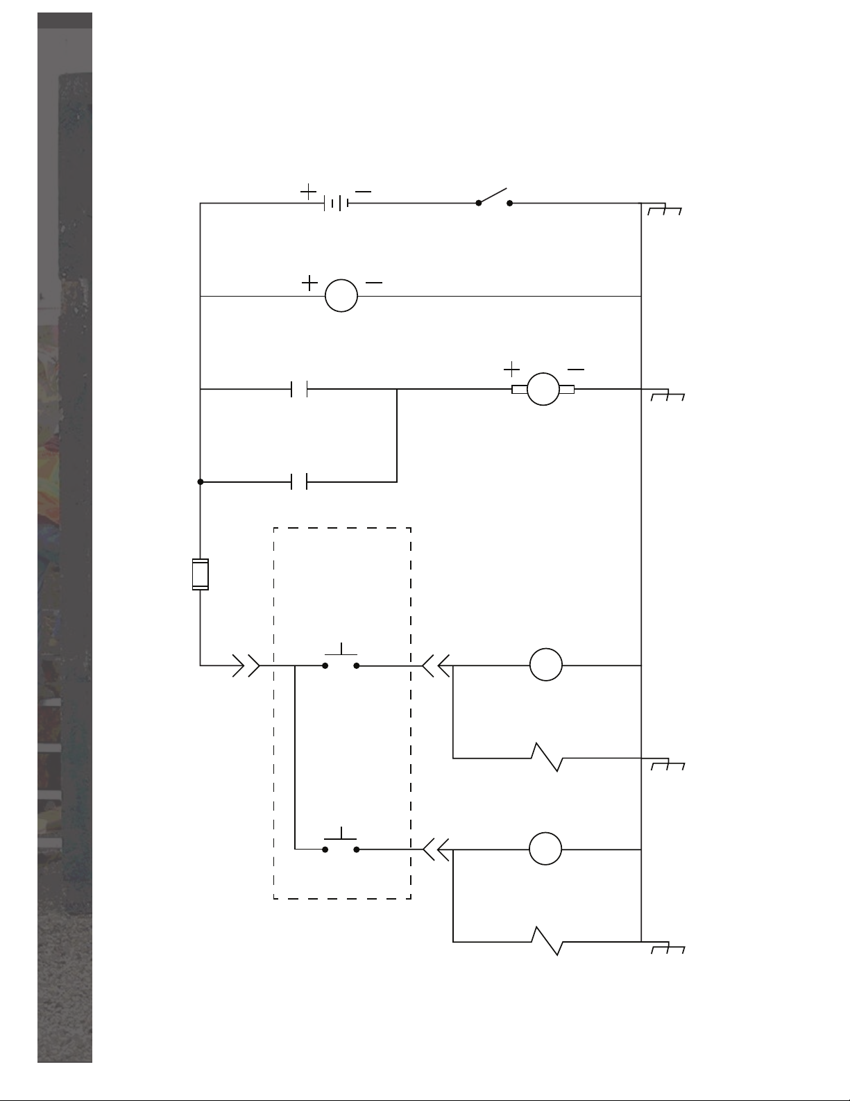
Corded Remote Push Button
INTERSTATE
SRM-4D 12 Volt
Marine/RV
Deep Cycle Battery
Red
10
Volt Meter
Red
20
Solenoid Set
Red
30
Red
40
Blk
10 Amp
50
Standard
Blade Style
Fuse
Contact
Solenoid Release
Contact
V
Cordless Remote
Push Button
Blk
Blk
Cole Hersee Master
Disconnect
(Minimum 11 Volts)
Hydraulic Motor
Chassis Ground
M
Set Push
Button
Blk
60
70
80
90
1
Blk
Release
Push
Button
Grn
Wht
Grn
4
Grn/Yel
Yel
2
Yel
Set Solenoid
S
Set Coil
Release Solenoid
S
Release Coil
Purple
Purple
30
40
28
Troubleshooting l JB Pipepuller
Page 30
Limited Warranty
Basinger Manufacturing hereby warrants the original purchaser
named below that this JB Pipepuller is free from defects in materials
and workmanship for a period of two years from the date of purchase.
Damage to this JB Pipepuller caused directly or indirectly by mis-
use, abuse, negligence, accidents, unapproved repairs or alterations,
and/or lack of maintenance voids all warranty terms. Basinger Man-
ufacturing will not be held liable for death, personal injury, property
damage, or for incidental, contingent, special or consequential dam-
ages resulting in the use of this product. For warranty questions or
inquiries, reference the contact information found in the introduction
section of this manual.
Purchaser:
_____________________
Date of Purchase:
_____________________
Model:
_____________________
Serial Number:
_____________________
JB Pipepuller l Limited Warranty
29
Page 31
Notes
30
Notes l JB Pipepuller
Page 32
JB Pipepuller l Notes
31
 Loading...