

Page 1
I. Description
MPC-XU Universal Crossover
For JBL MPC and MPA amplifiers
Owner’s Manual and Installation Guide
The MPC-XU is a dual-channel universal crossover filter accessory for use with JBL MPC
and MPA power amplifiers.
The MPC-XU is user configurable to fulfill these functions:
active crossover
bandpass filter
subsonic filter
ultrasonic filter
The MPC-XU allows independent filtering of the two audio channels. The choices are:
high-pass filtering (selection of 19 frequencies)
low-pass filtering (selection of 17 frequencies)
bandpass filtering (selection of any combination of the high-pass or low-pass frequencies)
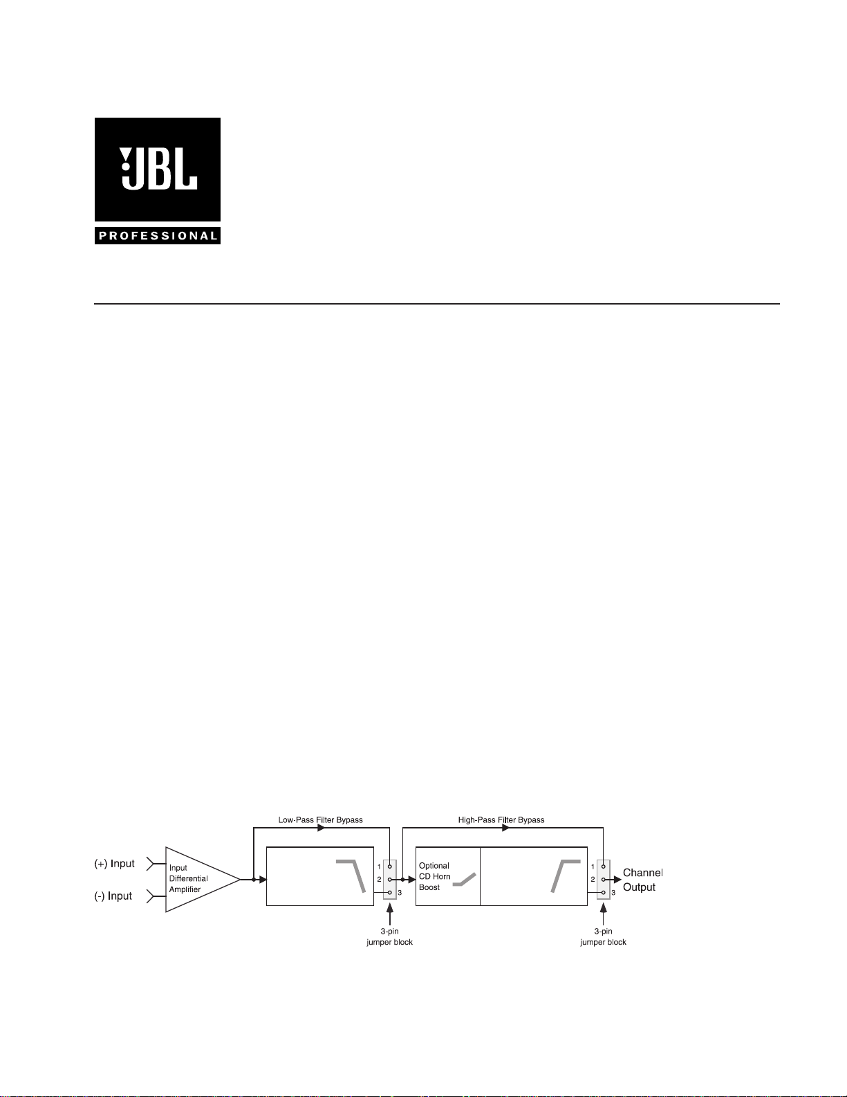
Figure 1. One channel of the MPC-XU
Each channel has an electronically balanced input and bypassable low-pass and high-pass
sections. Each filter circuit uses a 4-pole (24 dB/oct) Linkwitz-Riley alignment.
An alternative to the MPC-XU, the MPC-X100 is preset at 100 Hz for use only as a
subwoofer crossover.
The MPC-XU installs onto the amplifiers input card, where its settings are not easily accessible to the user. This makes the MPC-XU ideal for installed or rental sound systems, since it
practically eliminates the danger of unauthorized tampering with crossover setting or
incorrect crossover output connections, as well as the loudspeaker damage that may result
from such user tampering.
Installing the MPC-XU involves soldering a 10-pin and a 12-pin header into corresponding
holes on the input card, a process that only qualified technical persons should attempt. We
recommend that you enlist an authorized JBL service center to perform the task. See the
installation section of this manual for more information.
Figure 1 shows a block diagram of one channel of the MPC-XU:
Programmable
Linkwitz-Riley
Low-Pass Filter
Programmable
Linkwitz-Riley
High-Pass Filter
*TD-000082-00*
TD-000082-00
Rev. B
1
Page 2
II. Installation
CAUTION: The MPC-XU contains active components which can be damaged by electrostatic discharge (ESD). Be sure to practice standard ESD precautions, and always ground
yourself and your workstation before handling exposed circuit cards.
Installing the MPC-XU requires PC board soldering skills. Only qualified service technicians
should attempt it. Any authorized JBL service center can perform the installation.
The MPC-XU installs on the amplifier input board of any JBL MPA or MPC amplifier.
Tools needed:
Soldering iron
¼-inch (6.3 mm) nutdriver
Phillips screwdriver
Wire cutters
Rosin-core solder
Desoldering iron or other suitable desoldering equipment (Do not use desoldering braid; it can
damage the solder pads on the input board and might not remove solder adequately.)
CAUTION: Preparing the input board for installation of the MPC-XU involves removing
solder from feed-through holes on a 2-sided circuit board. Excessive heat can damage the
solder pads you will be working on. Proper equipment and experience with desoldering
delicate PC board circuitry is essential to successfully perform the procedure. Damage caused
by improper installation is not covered under warranty.
Input panel
CH2 CH1
10 10
12
88
66
14
44
18 18
22
24
0
-dB -dB
CH2 INPUT CH1
12
14
GROUND
STEREO
24
0
PARALLEL BRIDGE LEVELLEVEL
INPUT
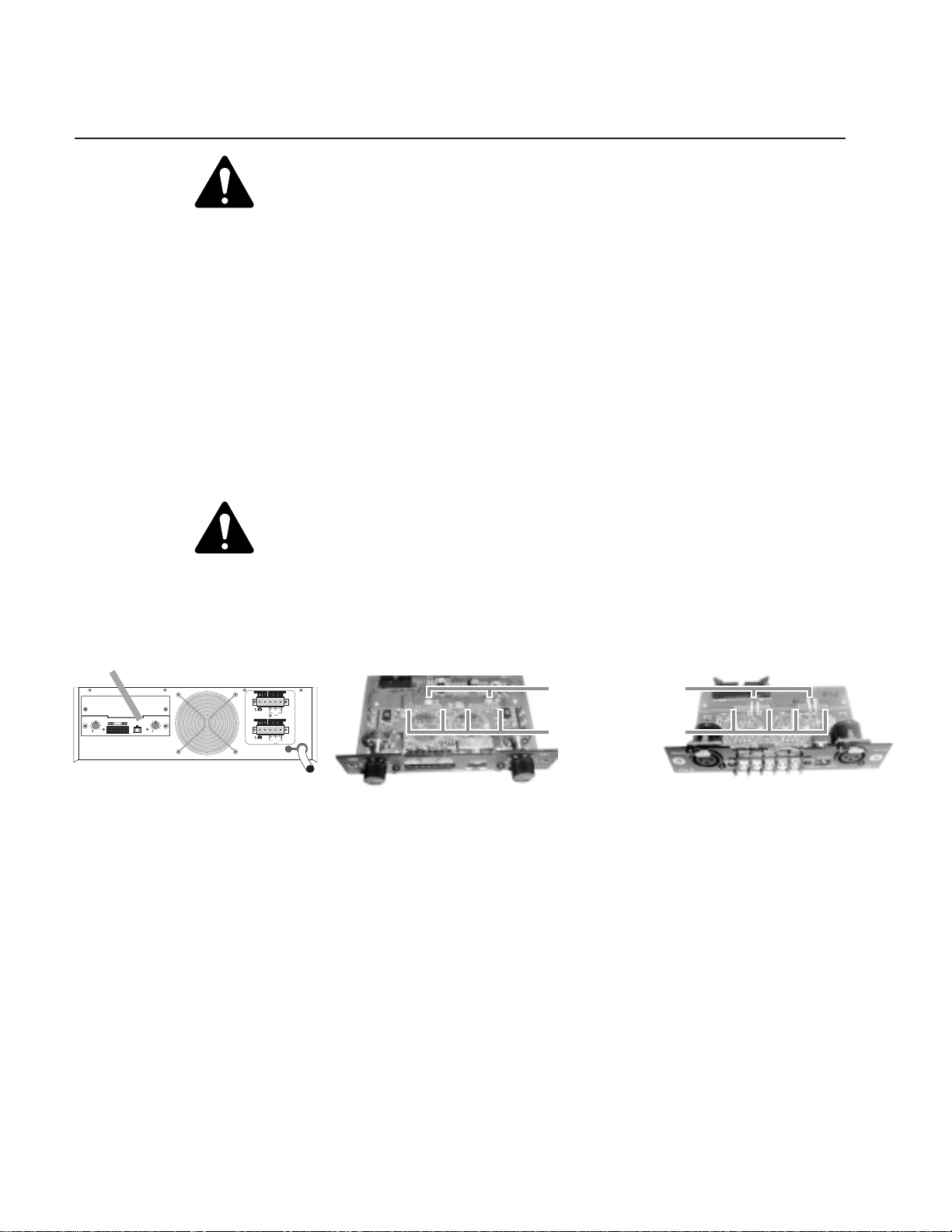
Figure 2a. The input panel’s location
on the rear panel of the amp
1 Turn off the amplifier and disconnect the AC power cord from the AC source. Disconnect
all cables from the amplifiers input panel.
2 Position the amplifier so the rear of the chassis is facing you. The input panel is located on
the left side of the rear panel. See Figure 2a.
LOW IMPEDANCE
AUDIO TRANSFORMER
CH1
CH1
070100
DIR. OUTPUT
ISOL.OUTPUT
70V
25V
BRIDGE
100V
MONO
LOW IMPEDANCE
AUDIO TRANSFORMER
CH2
CH2
070100
DIR. OUTPUT
ISOL.OUTPUT
70V
25V
BRIDGE
100V
MONO
Figure 2b. The input panel (MPC)
Wire jumpers: W303/304 and
W403/404 (MPC); or W305/
306 and W405/W406 (MPA)
Solder holes for MPC-XU
Figure 2c. The input panel (MPA)
3 Locate and remove the screws securing both the upper blank and the lower input panels to
the rear side of the chassis (2 screws on each mini panel). The upper blank panel will
simply drop off when its screws are removed.
4 Gently pull the lower input panel out from the amplifier. Once it is removed, you will
notice a ribbon cable connecting the input PC board to the amplifier. Disengage the
locking wing clamps on the ribbon header and carefully remove the ribbon head from the
socket on the board. Now the input panel assembly is completely free from the amplifier.
5 Desolder and remove the wire jumper pairs indicated in Figure 2b or 2c.
6 Under where the jumpers were located, youll find two rows of solder pad holesone
with 10 holes and another with 12 holes. Remove the solder from all 22 holes.
7 With the input panel facing you and the component side of the MPC-XU board facing
away from you, carefully insert the header pins of the MPC-XU fully into the socket holes.
Turn the assembly over and solder the MPC-XU in place. Make sure all the header pins are
well soldered. Visually inspect for cold solder joints and verify that you have sufficient
clearance to re-install the ribbon connector on the top side of the assembly. Finish by
trimming the MPC-XU header pins as required.
2
Page 3
NOISE SHIELD
#4-40 NUT
CH. 1 GAIN CONTROL
NOISE SHIELD
INPUT PANEL PCB
TAB
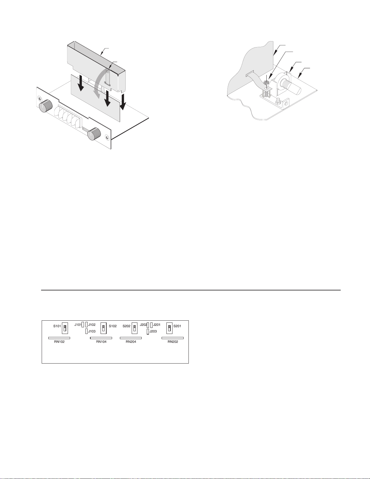
Figure 3 Figure 4
8 If you need to make any adjustments to the MPC-XU settings or if you need to record
them, do so now, because the MPC-XU will be inaccessible once the noise shield is
installed and the input panel is re-installed into the amplifier chassis. See Section III,
Programming the MPC-XU, below.
9 Using a ¼-inch (6.3 mm) nutdriver, remove the outer 4-40 nut from the stud in the panel
mounting bracket, next to Channel 1s gain control potentiometer. Place the noise shield
over the circuit board of the MPC-XU (Figure 3) and bend the grounding tab down so its
hole goes over the stud. Re-install the nut, and tighten it securely (Figure 4).
10 Reconnect the ribbon cable to the input board connector. Press the locking clamp wings
of the connector closed. You will feel them snap into place.
11 Carefully reposition the input board/MPC-XU assembly into the amplifier chassis and
secure it by fastening the two mounting screws. Make sure the screws are tightened snugly,
but do not over-torque them. Re-install the upper blank panel.
Installation of the MPC-XU is now complete, and the amplifier is now ready to be installed
into the system.
III. Programming the MPC-XU
The MPC-XU board has four switches, six 3-pin headers, and four SIP resistor network
sockets (see Figure 3). All these are used for programming the module. The circuitry for the
Figure 5. The MPC-XU’s switches, jumpers, and resistor networks.
Setting input operating mode on amplifier or input card
The input board or accessory on which the MPC-XU is installed has provisionsswitches or
headersfor setting the operating mode of the amplifier. In the signal flow, the MPC-XU is
located after these switches or headers, so its operation is affected by the mode setting.
Stereo or Parallel Mode OperationIf the amplifier is to be used in stereo or parallel
modes, configure both channels of the MPC-XU accordingly.
two channels is identical, so the switches, headers and sockets
are divided between them: those designated by a 3-digit
number starting in a 1 (switches S101 and S102, headers J101,
J102 and J103; and SIP resistor network sockets RN102 and
RN104) are for Channel 1, while those with a 3-digit number
starting in a 2 are for Channel 2. The following instructions
will use an x in place of the first digit, except where a specific
channel reference is necessary.
Bridged Mode OperationIf the amplifier is to be used in bridged mono mode, bypass
Channel 2 of the MPC-XU and use only Channel 1s input and processing.
3
Page 4

Figure 6
Bypassing the filters
To completely bypass the filter circuitry of a channel, set the jumpers on both Jx01 and Jx02
across pins 1 and 2, which are the upper two pins on their headers (see Figure 6). Note: If you
neglect to place jumpers on either header, no signal will pass on that channel.
ni10xShctiwS
noitisop"1×"
zH08zH008K021
zH001zH0001K28
zH021zH0021K86
zH061zH0061K65
zH002zH0002K74
zH052zH0052K33
zH005zH0005K81
zH008zH0008K21
zH0061zH00061K6.5
zH0002zH00002K7.4
Low-pass filter frequency table
ni20xShctiwS
noitisop"1×"
zH02zH002K021
zH03zH003K28
zH04zH004K65
zH05zH005K74
zH08zH008K72
zH001zH0001K22
zH021zH0021K02
zH051zH0051K51
zH002zH0002K21
zH004zH0004K6.5
zH005zH0005K7.4
zH008zH0008
High-pass filter frequency table
ni10xShctiwS
noitisop"01×"
20xNRni
Programming the low-pass filter
krowtenrotsiseR
Bypass/enable headerTo use the low-pass filter, set the jumper on
Jx01 across pins 2 and 3, which are the lower two pins on their header.
But if you do not wish to use the low-pass filter and want to bypass it
instead, set the jumper across pins 1 and 2.
Setting frequencyTo set the corner frequency (at which the output
is 6 dB down) of the low-pass filter section, choose the appropriate
resistor network value and switch setting for RNx02 and Sx01, respectively. (Sx01 is a ×10 range switch. In its upper position, the frequency
range is ×10; in the lower it is ×1.) Use the low-pass table to select the
right combination. See the appendix of this manual for keys to
identifying the correct resistor network.
Inserting the resistor networkIf there is a resistor network already
installed in the socket, carefully pull it straight out. Insert the pins of
the new resistor network into the socket holes and carefully press the
network into the socket. Be careful to avoid bending the pins of the
resistor network. Orientation of the resistor network is unimportant, as
long as all 8 pins are well seated in the socket.
ni20xShctiwS
noitisop"01×"
40xNRni
Programming the high-pass filter
krowtenrotsiseR
Bypass/enable headerTo use either the high-pass filter or the
constant-directivity horn equalization, or both, set the jumper on Jx02
across pins 2 and 3, which are the lower two pins on their header. But
if you do not wish to use either one of these functions and want to
bypass them, then set the jumper across pins 1 and 2.
Setting frequencyTo set the corner frequency (at which the output
is 6 dB down) of the high-pass filter section, choose the appropriate
resistor network value and switch setting the RNx04 and Sx02,
respectively. (Sx02 is a ×10 range switch. In its upper position, the
frequency range is x10, in the lower it is ×1.) Use the high-pass table to
select the right combination. See the appendix of this manual for keys
to identifying the correct resistor network.
Inserting the resistor networkIf there is a resistor network already
installed in the socket, carefully pull it straight out. Insert the pins of
the new resistor network into the socket holes and carefully press the
" K7.2
network into the socket. Be careful to avoid bending the pins of the
resistor network. Orientation of the resistor network is unimportant, as
long as all 8 pins are well seated in the socket.
4
Page 5

CD Horn Equalization (Boost)In addition to enabling the high-pass filter at Jx02, if you
opt for CD horn equalization you must place a jumper at Jx03 as well. The MPC-XU offers
two equalization curves for CD horn correction:
For +6 dB of boost at 20 kHz, place the jumper across pins 1 and 2 of Jx03.
For +10 dB of boost at 20 kHz, place the jumper across pins 2 and 3 of Jx03.
To bypass the CD Horn Equalization, do not place a jumper in one position or the other.
2&1sniP3&2sniPenoN
The table at left is a summary of the jumper
settings for the MPC-XU.
noitcnuFredaeH
ssap-wolssapyB101JX
ssap-wolelbanE101JX
ssap-hgihssapyB201JX
:1lennahC
:2lennahC
ssap-hgihelbanE201JX
tsoobnrohDCelbasiD301JX
zHk02@Bd6+,tsoobnrohDC301JX
zHk02@Bd01+,tsoobnrohDC301JX
ssap-wolssapyB102JX
ssap-wolelbanE102JX
ssap-hgihssapyB202JX
ssap-hgihelbanE202JX
tsoobnrohDCelbasiD302JX
zHk02@Bd6+,tsoobnrohDC302JX
zHk02@Bd01+,tsoobnrohDC302JX
IV. Typical configurations
Subsonic Filter (Infrasonic Filter)
Applications: Subsonic filters are commonly used in sound installations to filter out rumbles
and other inaudible or unwanted low frequency signals and to protect speaker tuned vented
speakers from damage due to excessive energy below the tuning frequency.
For a subsonic filter, determine the lowest useable frequency that the speaker can safely
handle and set the high-pass filter to that frequency. Typical subsonic filters are set at 50 Hz, 40
Hz, 30 Hz or 20 Hz.
Program settings:
1 Set Jx01 to bypass the low-pass filter (if not using) by placing jumper across pins 1 and 2.
2 Set Jx02 to enable the high-pass filter by placing jumper across pins 2 and 3.
3 No jumper on Jx03.
4 Insert proper resistor network in RNx04 socket.
5
Page 6

High-pass
freq. (set
by RNx04
and Sx02)
Low-pass
freq. (set
by RNx02
and Sx01)
Ultrasonic Filter
Applications: An ultrasonic filter is useful for minimizing RF interference, oscillations,
leakage or aliasing from digital devices, or other signals that are too high in pitch to hear but
may wreak havoc in an amplifier system.
Typical ultrasonic filters are set at 16 kHz or 20 kHz.
Program settings:
1 Set Jx01 to enable the low-pass filter by placing jumper across pins 2 and 3.
2 Set Jx02 to disable the high-pass filter (if not using) by placing jumper across pins 1 and 2.
3 No jumper on Jx03.
4 Insert proper resistor network in RNx02 socket.
Bandpass Filter
Applications: A bandpass filter is useful if the speaker system has a limited bandwidth.
Program settings:
1 Set Jx01 to enable the low-pass filter by placing jumper across pins 2 and 3.
2 Set Jx02 to enable the high-pass filter by placing jumper across pins 2 and 3.
3 No jumper on Jx03.
4 Insert proper resistor network corresponding to the lower limit of the desired passband in
RNx04 socket.
5 Insert proper resistor network corresponding to the upper limit of the desired passband in
RNx02 socket.
CD Horn Equalization Filter
Applications: A constant directivity horn requires a 6 dB per octave boost at high frequen-
cies to provide a flat frequency response. On the MPC-XU you must use the CD horn
equalization in conjunction with the high-pass filter.
Program settings:
1 Set Jx01 to bypass the low-pass filter (if not using) by placing jumper across pins 1 and 2.
2 Set Jx02 to enable the high-pass filter by placing jumper across pins 2 and 3.
3 Set Jx03 to select the EQ curve you desire: across pins 1 and 2 to +6 dB at 20 kHz, or
across pins 2 and 3 for +10 dB at 20 kHz.
Subsonic Filter with CD Horn EQ
Applications: This would be suitable only if the loudspeaker system uses a passive crossover.
Program settings: Use settings 1, 2 and 4 from the subsonic filter instructions and setting 3
from the CD horn equalization filter instructions above.
Subsonic and Ultrasonic Filter
Program settings: Use settings 2, 3 and 4 from the subsonic filter instructions along with 2
and 3 from the ultrasonic filter instructions above.
6
Page 7

MPC-XU
2-Way Active Crossover
This configuration routes the frequencies below a particular frequency to amplifier Channel 1,
which will driver the low-frequency speaker(s), and the frequencies above to Channel 2, which
will drive the high-frequency speaker(s). Using the MPC-XU as a crossover requires that you
drive both amplifier inputs with the same full-band signal.
Program settings:
1 On the input module, set the amplifer mode to parallel. Alternately, you could use a Y-
cable to provide the same signal to both channel inputs.
Channel 1:
2 Set J101 to enable the Channel 1s low-pass filter by placing jumper across pins 2 and 3.
3 No jumper on J103.
4 Insert a resistor network into RN102 that is appropriate to the desired crossover frequency.
5 Subsonic (infrasonic) filterIf you need subsonic (infrasonic) filtering, set J102 to enable
the high-pass filter by placing jumper across pins 2 and 3, and insert a resistor network into
RN104 corresponding to the roll-off frequency you desire. If you do not want subsonic
(infrasonic) filtering, set J102 to disable the high-pass filter by placing jumper across pins 1
and 2.
Channel 2:
6 Set J202 to enable the Channel 2s high-pass filter by placing jumper across pins 2 and 3.
7 Insert a resistor network into RN204 that is appropriate to the desired crossover frequency.
8 CD horn EQIf you need equalization for a constant-directivity horn, set a jumper on
J203 for the amount of boost you need. If you do not want CD horn equalization, do not
place any jumper on J203.
9 Ultrasonic filteringIf you need ultrasonic filtering, set a jumper on J201 across pins 2 and 3
to enable Channel 2s Low-pass filter and insert a resistor network into RN202 that
corresponds to the desired roll-off frequency. If you do not want any ultrasonic filtering,
set the jumper on J201 across pins 1 and 2 to bypass the low-pass filter.
Multi-way Crossover System
The MPC-XU allows you to set up 3- and even 4-way systems. Of course, this also requires that
you use more than one amplifier and more than one MPC-XU. You must feed each amplifier
with the same full-range signal and use the MPC-XU to filter the signals in the individual channels.
Each MPC-XU should be configured in the bandpass filter configuration as described above.
7
Page 8

V. Warranty & Contacting JBL
These products are designed and backed by JBL Professional, the world leader in sound
reinforcement. For complete JBL warranty information, to order replacement parts or to ask
for clarifications to this manual, contact JBL Professional:
Within the United States: Contact the Applications Dept, JBL Professional, PO Box 2200, 8500
Balboa Blvd, Northridge CA 91329 USA. In the USA you may call Monday through Friday
8:00 a.m. to 5:00 p.m. Pacific Coast Time: (818) 894-8850.
In other areas throughout the world: Contact the JBL Professional Distributor in you country.
A list of JBL Professional Distributors and U.S. Service Centers can be attained from the JBL
Professional website: www .jb lpro.com.
Appendix
Identifying resistor networks
Use this chart to identify the values of the resistor networks. See the tables on page 4 to find
the correct values for the desired filter frequencies.
Use only these three digits to
determine resistance code.
Disregard the other
numerals and letters.
RESISTANCE
2.7K
3.9K
4.7K
5.6K
6.8K
8.2K
10K
12K
15K
18K
20K
22K
27K
33K
39K
47K
56K
68K
CODE
272
392
472
562
682
822
103
123
153
183
203
223
273
333
393
473
563
683
JBL Professional 8500 Balboa Boulevard, P.O. Box 2200 Northridge, California 91329 U.S.A.
A Harman International Company MPC-XU MANUAL 3/99
8
 Loading...