

Page 1
Linear Spatial Reference
Key Features:
䉴
Advanced Linear Spatial Reference
design ensures flatter response at the
mix position.
䉴
Differential Drive®technology with
dynamic braking for extended low
frequency response and low power
compression.
䉴
Neodymium midrange with 2" voice
coil and Kevlar™ cone material for
extended frequency response and
low distortion.
䉴
Titanium composite high frequency
transducer with elliptical oblate
spheroidal waveguide and damped
polepiece.
䉴
High-Density baffle for low enclosure
resonance and stable inertial ground.
䉴
Linear Dynamics Aperture port
design eliminates port turbulence
and reduces port compression.
䉴
Magnetically shielded for use near
video monitors.
䉴
Reinforced enclosure and convenient
mounting points allow mounted
installation.
䉴
Midrange/high frequency sub-baffle
may be rotated by user for horizontal
or vertical orientation.
䉴
Available as mirror imaged left and
right models. (order LSR6332L or
LSR6332R)
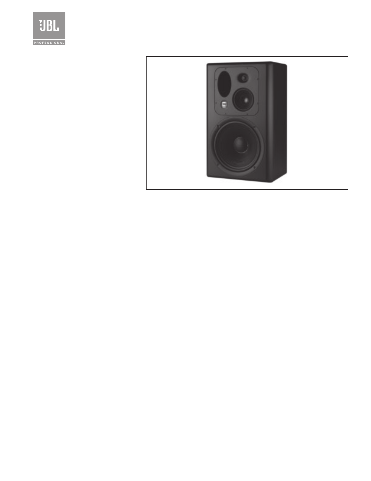
The LSR6332 studio monitor is
designed for use as a near or mid-field
reference monitor, or a soffit-mounted
main monitor in applications requiring
exceptional spectral accuracy and high
SPL capability. The LSR6332 combines
the latest in JBL’s renowned transducer
and system technology with psychoacoustically derived spatial response criteria, resulting in a more accurate studio monitoring reference. In this design
process, the system’s frequency
response over the forward listening
range (±15° vertically and ±30° horizontally) is optimized, as opposed to
the conventional approach of optimizing the response directly on-axis. This
design approach involves careful component design, selection of crossover
frequency, and precise baffle geometry
and detail. The result is a system that
can be used for the most critical judgements of recording balance, image
placement, and equalization.
LSR6332
LSR6332R (Right) shown
Studio Monitor System
252G Low Frequency Transducer
The neodymium 12" woofer is based on JBL patented Differential Drive
technology. With the neodymium structure and dual drive coils, power compression is kept to a minimum to reduce spectral shift as power level increase.
An added third coil between the drive coils acts as a dynamic brake to limit
excess excursion and reduce audible distortion at the highest levels. The cone is
made of a graphite polypropylene composite forming a rigid piston supported
by a soft butyl rubber surround.
®
C500G Midrange Transducer
The 5" midrange transducer has a 2" neodymium magnetic structure with a
woven Kevlar cone. The powerful motor structure was chosen to support the
low crossover frequency to the woofer. In order to achieve the goal of accurate
spatial response the crossover points are placed at 250 Hz and 2.2 kHz. These
transition points match the directivity characteristics of the three transducers.
053TiS High Frequency Transducer
The high frequency transducer has a composite diaphragm integrated with an
Elliptical Oblate Spheroidal (EOS) waveguide with wide uniform dispersion,
which is critical to the smooth spatial response required in today’s working
environments. The mid and high frequency devices are mounted within millimeters of each other on a cast aluminum sub-baffle that can be rotated for
horizontal or vertical placement, giving maximum flexibility in placement to
reduce console and ceiling splash that interferes with stereo imaging and depth.
Page 2
䉴 LSR6332 Linear Spatial Reference Studio Monitor System
Dividing Network
The impedance compensated crossover filters are optimized to yield 4th-order (24 dB/octave) Linkwitz-Riley
electroacoustic responses from each transducer (in-phase,
-6 dB at crossover). In order to achieve optimal symmetrical response in the vertical plane, both magnitude and
phase compensation are implemented in the dividing network. The network allows the user to attenuate the high
frequency level above 3 kHz by 1 dB. This adjusts for
spectral balance when used in bright rooms. Components
used in the network are exclusively low-loss metal film
capacitors, low distortion electrolytic capacitors, high-Q
high saturation current inductors and high current sandcast power resistors.t
HF Adjustment Flat and -1 dB Settings
Linear Spatial Response Measurement Techniques
We all know that many loudspeakers have similar measurements but sound different. By going beyond simple
on-axis frequency response measurements, JBL defines
the ultimate performance specification for new systems –
what it will sound like in your room.
While other manufacturers use a single on-axis frequency response measurement taken at one point in space, JBL
measures monitor systems over a sphere that encompasses
all power radiated into the listening room – in every
direction. This data reflects 1296 times the information of
a single on-axis response curve. Seventy-two measure-
ments of the direct sound field, the reflected sound field,
and the reverberant field, the entire sound field heard by
the listener, is correlated to optimize response at the listening position. In place of spectral smoothing used by
some manufacturers which actually conceals data, the JBL
approach actually exposes flaws in systems, such as resonances, poor dispersion and other causes of off-axis coloration.
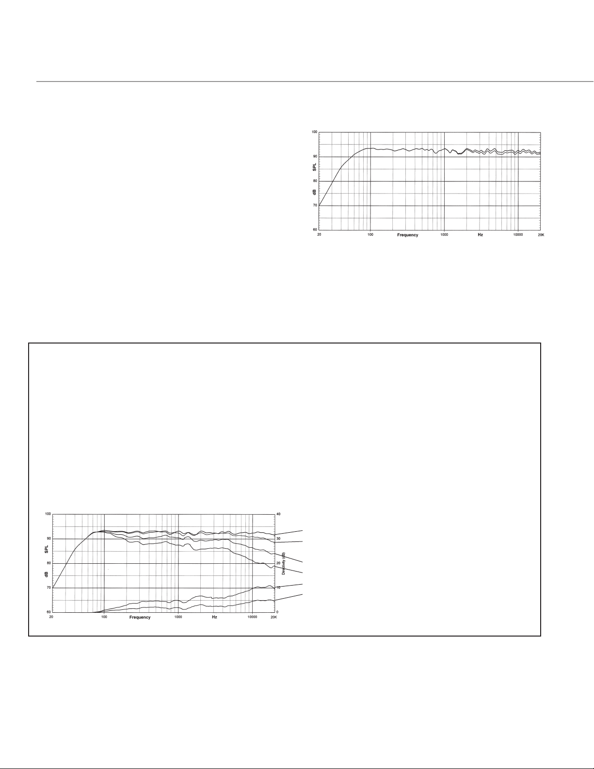
The data shown below is a set of spatially measured
graphs that are the heart of JBL’s philosophy.
LSR6332 Response Curves
1. On-Axis Response
2. Spatially Averaged Response over a range of +/- 30°
Horizontal & +/- 15° Vertical
3. First Reflection Sound Power
4. Total Radiated Sound Power
5. DI of On-Axis Response
6. DI of First Reflections
Page 3

Specifications:
System:
Transducers:
Physical:
Caution: Unsafe mounting or overhead suspension of any heavy load can result in serious injury and
equipment damage. Mounting of speakers should be done by qualified persons in accordance with all
applicable local safety and construction standards. Be certain to follow the instructions provided by
the manufacturer of the mounting bracket. Before selecting a mounting bracket, be certain that it is
capable of supporting the weight of the speaker to be mounted.
Input Impedance (Nominal): 4 ohm
Anechoic Sensitivity1: 93 dB/2.83 V/1 m (90 dB/ 1 W/ 1 m)
Frequency Response (60 Hz – 22 kHz): +1. -1.5 dB
Low Frequency Extension
2
:
-3 dB: 54 Hz
-10 dB: 35 Hz
Enclosure Resonance Frequency: 33 Hz
Long Term Maximum
Power (IEC265-8): 200 W continuous average; 800 W peak
Recommended Amplifier Power: 150 W - 1000 W (rating into 4-ohm load)
High Frequency Control (2.5 to 20 kHz):
Distortion, 96 dB SPL, 1 m
Low Frequency (below 120 Hz):
Distortion, 102 dB SPL, 1 m
Low Frequency (below 120 Hz):
2nd Harmonic: <1.5%
3rd Harmonic: <1%
Mid and High Frequency
(120 Hz to 20 kHz):
2nd Harmonic: <0.5%
3rd Harmonic: <0.4%
2nd Harmonic: <1.5%
3rd Harmonic: <1%
Mid and High Frequency
(80 Hz to 20 kHz):
2nd Harmonic: <1%
0 dB, -1 dB
3
:
3
:
3rd Harmonic: <1% (Note: <0.4%, 250 Hz - 20 kHz)
Power Nonlinearity (20 Hz to 20 kHz):
Low-Mid Frequency Crossover:
4th Order Acoustic Linkwitz-Riley: 250 Hz
Mid-High Frequency Crossover:
4th Order Acoustic Linkwitz-Riley: 2.2 kHz
30 Watts: <0.4 dB
100 Watts: <1.0 dB
Low Frequency Model: 252G
Diameter: 300 mm (12 in)
Voice Coil: 50 mm (2 in) Differential Drive
coil
Magnet Type: Neodymium
Cone Type: Carbon Fiber Composite
Impedance: 4 ohms
Mid Frequency Model: C500G
Diameter: 125 mm (5 in)
Voice Coil: 50 mm (2 in) aluminum edge wound
Magnet Type: Neodymium
Cone Type: Kevlar™ composite
Impedance: 4 ohms
High Frequency Model: 053TiS
Diameter: 25 mm (1 in) diaphragm
Voice Coil: 25 mm (1 in)
Magnet Type: Ceramic 5
Diaphragm Type: Damped titanium composite
Other Features: Elliptical oblate spheroidal waveguide
Impedance: 4 ohms
Finish: Smooth dark graphite
Enclosure Volume (Net): 50 liter (1.8 cu ft)
Input Connectors: 5-way binding posts
Input Features: Bi-wirable
Mounting: 4 threaded mounting points conforming to industry
standard square pattern, 127 x 70 mm (5 x 2.75 in)
center to center. M6 metric thread.
Baffle Construction: Injection molded structural ABS
Enclosure Construction: 19 mm (3/4 in) MDF
Net Weight: 20.4 kg (45 lb)
Dimensions (WxHxD): 63.5 x 39.4 x 29.2 cm (25.0 x 15.5 x 11.5 in)
®
with dynamic braking
Amplitude & Phase
96 dB/1 m (Distortion raised 20 dB)
102 dB/1 m (Distortion raised 20 dB)
Notes:
All measurements unless otherwise stated made anechoically at 2 meters and referenced to 1 meter by the inverse square law.
The reference measurement microphone position is located perpendicular to the center line of the mid and high frequency transducers, at the point 55 mm (2.2 in) below
the center of the tweeter diaphragm
1
Mean SPL from 100 Hz to 20 kHz.
2
Describes anechoic (4) low frequency response. Acoustic loading provided by the
listening room will increase low frequency bass extension.
3
Distortion measurements performed with the input voltage necessary to produce the
stated A-weighted SPL at the stated measurement distance. Distortion figures refer to
the maximum distortion measured in any 1/10th octave wide band in the stated frequency range.
4
Power nonlinearity figures based on the A-weighted deviation from linear increase in
SPL with linear increase in input power (i.e., power compression) measured after 3
minutes of continuous pink noise excitation at the stated power input.
JBL continually engages in research related to performance improvements. New materials, production methods, and design refinements are introduced into existing products without notice as a routine expression of that philosophy. For this reason, any
current JBL product may differ in some respect from its published description, but will
always equal or exceed the original design specification unless otherwise stated.
Page 4

䉴 LSR6332 Linear Spatial Reference Studio Monitor System
Acoustic Contribution
System Impedance
Impulse Response
Power Compression
1 – 10 WATTS
2 – 30 WATTS
3 – 100 WATTS
Vertical And Horizontal Orientation
LSR6332R (Right) shown
JBL Professional
8500 Balboa Boulevard, P.O. Box 2200
Northridge, California 91329 U.S.A.
A Harman International Company
© Copyright 2004 JBL Professional
SS LSR6332
CRP 5M
8/05
 Loading...