

Page 1
VTX A8 | User Manual
Page 2

VTX A8 | User Manual
GENERAL INFORMATION
VTX A8 - User Manual
Document Number: 1000337283
Version: C - EN
Distribution Date: December 23, 2020
Copyright © 2020 by HARMAN International; all rights reserved
JBL PROFESSIONAL
8500 Balboa Blvd
Northridge, CA 91329
USA
Page 3
VTX A8 | User Manual
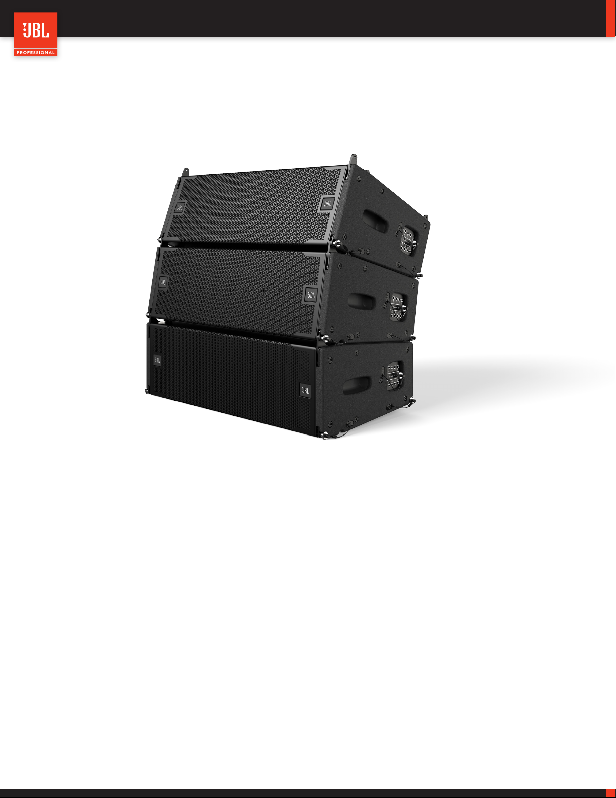
Thank you for purchasing JBL V TX Series products
In more than 75 years of JBL innovations, the VTX Series stands apart as a milestone in the practical application of cre-
ative engineering. VTX products herald the next generation in line array loudspeaker systems: a new era in performance,
system integration and user friendliness. VTX products draw on multiple JBL patents in driver, waveguide, and suspension
technology, as well as custom amplification, DSP, control, and system management designs created in collaboration with
HARMAN Professional sister companies.
VTX loudspeakers marry custom transducer design and in-house manufacture, breakthrough technologies, and a com-
prehensive system approach to deliver a premium experience for all who come into contact with it, from the FOH mixing
engineer to the systems engineer, rigger, road crew, warehouse manager, and, of course, the audience. Designed for
operators of portable and fixed systems alike, the VTX Series features JBL’s legendary sound quality coupled with expert
support and advanced tools that enable optimal specification, configuration, and operation of VTX systems in any venue,
anywhere in the world. The VTX Series delivers a comprehensive solution: the finest sound quality available, plus efficient
and intuitive setup, tuning, networking, and control.
Page 4

VTX A8 | User Manual
TABLE OF CONTENTS
1 - DECLARATION OF CONFORMITY ...........................................................................6
2 - SAFETY .................................................................................................7
2.1 Safety Instructions ....................................................................................7
2.2 General Hardware Information ..........................................................................7
2.3 Attachment to Structures ...............................................................................7
2.4 Important Safety Warning ..............................................................................8
2.5 Are You New to Rigging? ..............................................................................8
2.6 Inspection and Maintenance ............................................................................8
2.7 Symbols ............................................................................................9
3 - SYSTEM COMPONENTS .................................................................................10
4 - COMPATIBLE ACCESSORIES ..............................................................................11
4.1 VTX A8 AF - Array Frame ..............................................................................11
4.2 VTX A8 AF EB - Array Frame Extension Bar ...............................................................11
4.3 VTX A8 MF - Mini Frame ..............................................................................11
4.4 VTX A8 SB - Suspension Bar ...........................................................................12
4.5 VTX A8 VT - Vertical Transporter ........................................................................12
4.6 VTX A8 VT CVR - Soft Cover ...........................................................................12
4.7 VTX A8 BP - Base Plate ...............................................................................12
4.8 VTX RC500 - Rotating Clamp. . . . . . . . . . . . . . . . . . . . . . . . . . . . . . . . . . . . . . . . . . . . . . . . . . . . . . . . . . . . . . . . . . . . . . . . . . . 13
4.9 VTX Delta - Delta Plate ................................................................................13
5 - SOFTWARE .............................................................................................14
5.1 Line Array Calculator 3 TM .............................................................................14
5.2 Array Link TM .......................................................................................14
5.3 Performance Manager TM ..............................................................................14
6 - INTRODUCTION .........................................................................................15
6.1 VTX A8 ............................................................................................15
6.2 VTX B18 ...........................................................................................16
7 - CONNECTIONS .........................................................................................17
7.1 A8 Internal Wiring ....................................................................................18
7.2 B18 Internal Wiring ...................................................................................18
8 - SYSTEM AMPLIFICATION & WIRING ........................................................................19
8.1 Using A8 With Crown I-Tech 4X3500HD ..................................................................19
8.2 Using A8 With Crown I-Tech HD (2-CH) ...................................................................20
8.3 Using A8 and B18 With I-Tech 4X3500HD .................................................................21
Page 5

VTX A8 | User Manual
8.4 Using A8 and B28 With I-Tech 4X3500HD .................................................................22
8.5 Crown V-Rack ......................................................................................22
9 - VTX A8 PRESET LIBRARY .................................................................................23
9.1 VTX A8 Preset Modes and Options ......................................................................23
9.2 VTX B18/B28 Preset Modes and Options .................................................................23
10 - SUBWOOFER OPTIONS .................................................................................24
10.1 SUB / LF Preset Options ..............................................................................24
10.2 Time Alignment .....................................................................................25
11 - CONFIGURATION EXAMPLES ............................................................................26
11.1 Small A8 System ...................................................................................26
11.2 Medium A8 System .................................................................................26
11.3 Large A8 System ...................................................................................27
11.4 Large A8 and A12 System ............................................................................27
12 - FREQUENCY RESPONSE ................................................................................28
13 - LINE ARRAY CONTROL PANEL ...........................................................................29
13.1 Accessing LACP ....................................................................................29
13.2 Filter 1 - Array Size Compensation .....................................................................30
13.3 Filter 2 - Atmospheric Absorption Compensation ..........................................................30
13.4 Filter 3 - HF Throw Distance Compensation ..............................................................30
13.5 Filters 4 & 5 - User PEQ 1 & 2 .........................................................................30
13.6 Example using LACP ................................................................................31
14 - TESTING THE VTX A8 ...................................................................................32
14.1 Using a DMM (Digital Multi Meter) ......................................................................32
14.2 Testing Individual components ........................................................................33
14.3 Using Performance Manager ..........................................................................34
13.4 Performance Manager Readings .......................................................................34
15 - SPECIFICATIONS .......................................................................................35
16 - ACOUSTIC MEASUREMENTS ............................................................................36
17 - DIMENSIONS ..........................................................................................36
18 - CONTACT INFORMATION ................................................................................37
Page 6
1 - DECLARATION OF CONFORMITY
BRAND: JBL Professional
FAMILY NAME: VTX A8 loudspeaker and suspension accessories
MODEL NAMES:
VTX A8 | User Manual
• VTX A8
• VTX A8 AF
• VTX A8 AF EB
• VTX A8 MF
• VTX A8 SB
• VTX A8 BP
We, HARMAN International, declare under our sole responsibility that the product, to which this declaration relates, is in conformity
with the following standards:
STANDARD DESCRIPTION TEST AGENCY
2006/42/EC
MACHINERY DIRECTIVE
• VTX RC500
• VTX A8 VT
Applies to machinery and lays down essential
health and safety requirements
ISO12100
Tested at JBL Professional
2014/35/EC
LOW VOLTAGE DIRECTIVE
Applies to loudspeaker and lays down essential
health and safety requirements.
EN60065
Frank Lacelle
Compliance Manager - Harman International
Tested at JBL Professional
Page 7

VTX A8 | User Manual
2 - SAFETY
2.1 SAFETY INSTRUCTIONS
1. Read these instructions.
2. Keep these instructions.
3. Heed all warnings.
4. Follow all instructions.
5. Do not expose the product to direct rain or sea spray.
6. Clean only with a dry cloth.
7. Do not install near any heat sources such as radiators, heat registers, stoves, or other apparatus that produce heat.
8. Only use attachments/accessories specified by the manufacturer.
9. Use only with a cart, stand, tripod, bracket, or table specified by the manufacturer or sold with the apparatus. When a cart is used,
use caution when moving the cart/apparatus combination to avoid injury from tip-over.
10. Refer all servicing to qualified service personnel. Servicing is required when the apparatus has been damaged in any way, such as if
liquid has been spilled or objects have fallen into the apparatus, or if the apparatus has been exposed to rain or moisture, does not
operate normally, or has been dropped.
11. Contact JBL Professional for advanced servicing issues.
12. CAUTION - DO NOT PERFORM ANY SERVICING UNLESS YOU ARE QUALIFIED TO DO SO.
13. Prolonged exposure to excessive SPL can cause hearing damage. The loudspeaker is easily capable of generating sound pressure
levels (SPL) sufficient to cause permanent hearing damage to performers, production crew, and audience members. Caution should
be taken to avoid prolonged exposure to SPL in excess of 90 dB.
14. Read the System Rigging Manual before installation and use of the product.
2.2 GENERAL HARDWARE INFORMATION
Any hardware used in an overhead suspension application must be load rated for the intended use. Generally, this type of hardware
is available from rigging supply houses, industrial supply catalogs, and specialized rigging distributors. Local hardware stores do not
usually stock these products. Compliant hardware will be referenced with a working load limit (WLL) and a traceability code.
2.3 ATTACHMENT TO STRUCTURES
A licensed Professional Engineer must approve the placement and method of attachment to the structure prior to the installation of any
overhead object. The following performance standards should be provided to the Professional Engineer for design purposes: Uniform
Building Code as applicable, Municipal Building Code as applicable, and Seismic Code as applicable. The installation of the hardware
and method of attachment must be carried out in the manner specified by the Professional Engineer. Improper installation may result in
damage, injury, or death.
7
Page 8

VTX A8 | User Manual
2.4 IMPORTANT SAFETY WARNING
The information in this section has been assembled from recognized engineering data and is intended for informational purposes only.
None of the information in this section should be used without first obtaining competent advice with respect to applicability to a given
circumstance. None of the information presented herein is intended as a representation or warranty on the part of JBL. Anyone making
use of this information assumes all liability arising from such use.
All information presented herein is based upon materials and practices common to North America and may not directly apply to other
countries because of differing material dimensions, specifications, and/or local regulations. Users in other countries should consult with
appropriate engineering and regulatory authorities for specific guidelines.
Correct use of all included hardware is required for secure system suspension. Careful calculations should always be performed to
ensure that all components are used within their working load limits before the array is suspended. Never exceed the maximum recom-
mended load ratings.
Before suspending any speaker system, always inspect all components (enclosure, rigging frames, pins, eyebolts, track fittings, etc.) for
cracks, deformations, corrosion, or missing/loose/damaged parts that could reduce strength and safety of the array. Do not suspend
the speaker until the proper corrective action has been taken. Use only load-rated hardware when suspending JBL suspendable loud-
speaker models.
2.5 ARE YOU NEW TO RIGGING?
If you are new to rigging, you should:
• Know the rules for safe rigging.
• Attend a safe rigging seminar.
• Meet and establish a relationship with a licensed mechanical or structural engineer. Get in the habit of asking them questions in-
stead of assuming their answers. Learn from what they tell you.
• Research and understand the codes, practices and requirements of the venues where you intend to operate your sound system.
2.6 INSPECTION AND MAINTENANCE
Suspension systems are comprised of mechanical devices and, as such, require regular inspection and routine maintenance to ensure
proper functionality. Before suspending or pole mounting any speaker system, always inspect all components (enclosure, suspension
frames or brackets, pins, eyebolts, etc.) for cracks, deformations, corrosion, or missing/loose/damaged parts that could reduce strength
and safety of the array. Do not suspend or pole mount a speaker until the proper corrective action has been taken.
Installed systems should be inspected at least once a year. The inspection must include a visual survey of all corners and load-bearing
surfaces for signs of cracking, water damage, delamination, or any other condition that may decrease the strength of the loudspeaker
enclosure.
Accessory suspension hardware provided with or for VTX systems must be inspected for fatigue at least once a year or as required by
local ordinance. The inspection must include a visual survey of the material for signs of corrosion, bending, or any other condition that
may decrease the strength of the fastener. Additionally, any eyebolts must be checked for possible spin-out of the enclosure.
For all other hardware and fittings, refer to the hardware manufacturer’s inspection and maintenance guidelines for process.
8
Page 9
VTX A8 | User Manual
JBL is not responsible for the application of its products for any purpose or the misuse of this information for any purpose. Furthermore,
JBL is not responsible for the abuse of its products caused by avoiding compliance with inspection and maintenance procedures or
any other abuse.
Prior to suspending the system, an expert, trained and experienced in suspending speaker systems, should inspect all parts and com-
ponents.
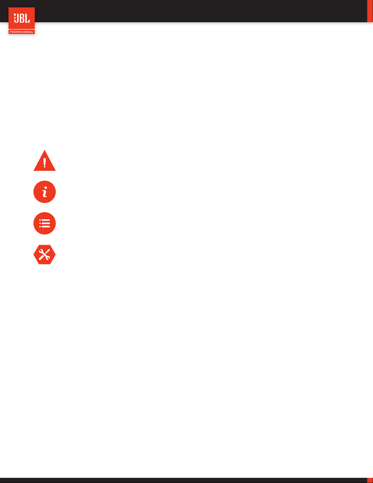
2.7 SYMBOLS
The following symbols are used in this document:
CAUTION: This symbol gives notice of a potential risk of harm to the individual or the equipment. Instruction
marked with this symbol must be strictly followed.
TIP: This symbol gives notice of helpful, relevant information about the topic.
INSTRUCTIONS: This symbol gives notice of instructions that must be followed for proper installation and use of
the product.
TOOLS REQUIRED: This symbol gives notice of tools that must be used for proper installation and use of the
product.
9
Page 10
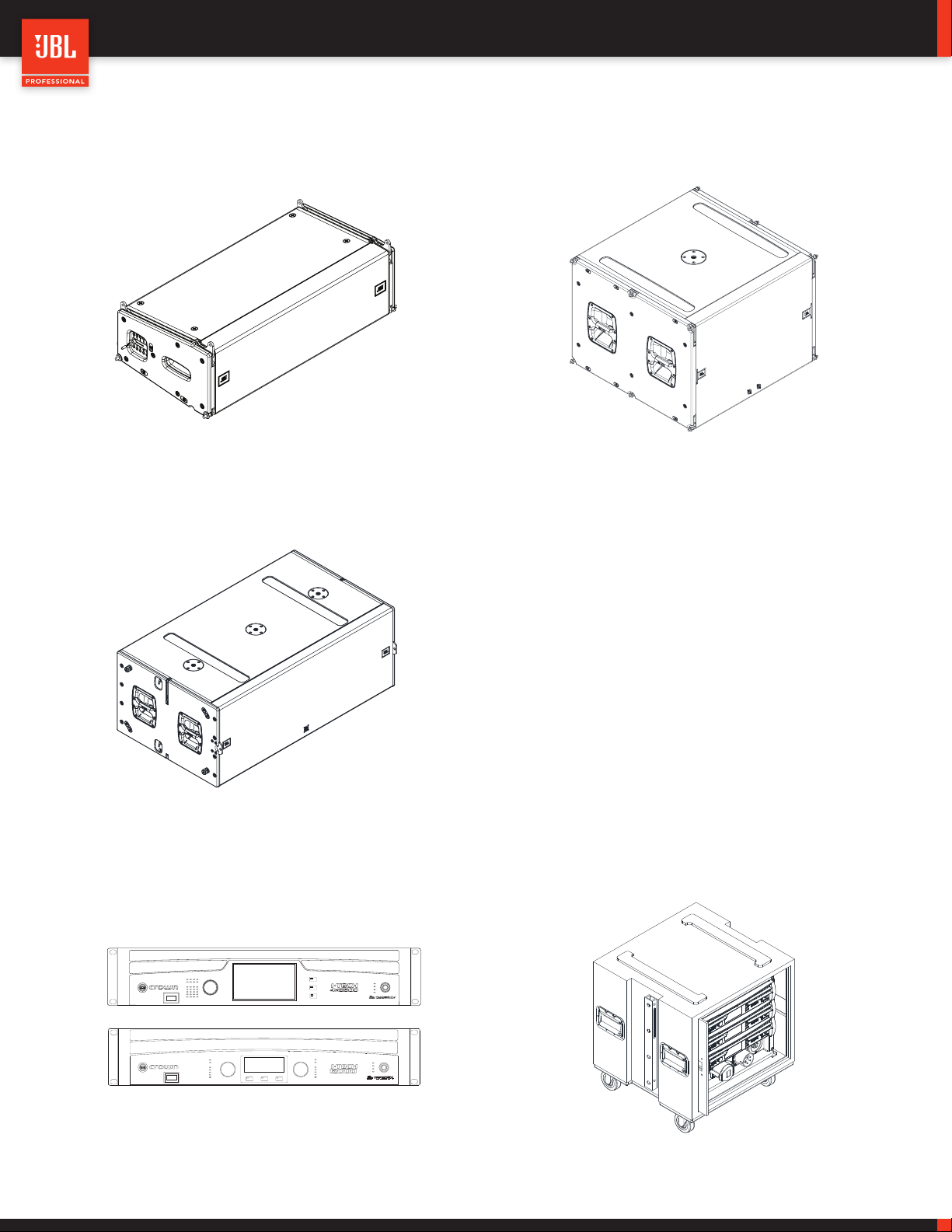
3 - SYSTEM COMPONENTS
VTX A8 VTX B18
VTX A8 | User Manual
VTX B28
Fault
Thermal
1
234
Clip
-10
-20
Signal
Ready
Fault
1
Thermal
1
Clip
-10
-20
Signal
Menu/Exit Prev Next
Ready
Menu/Exit
Prev
Next
Fault
2
Thermal
2
Clip
-10
-20
Signal
Ready
DRIVECORE SERIES
Power
Bridge 1/2
Bridge 3/4
Data
Power
Bridge 1/2
Bridge 3/4
Data
Crown I-Tech HD Amplifiers Crown Audio V-Rack
10
Page 11
VTX A8 | User Manual
4 - COMPATIBLE ACCESSORIES
All listed accessories are compatible with the VTX A8 and, in some cases, the VTX B18. For subwoofer specific accessories refer to the
B18 User Manual and Rigging Manual found at www.jblpro.com.
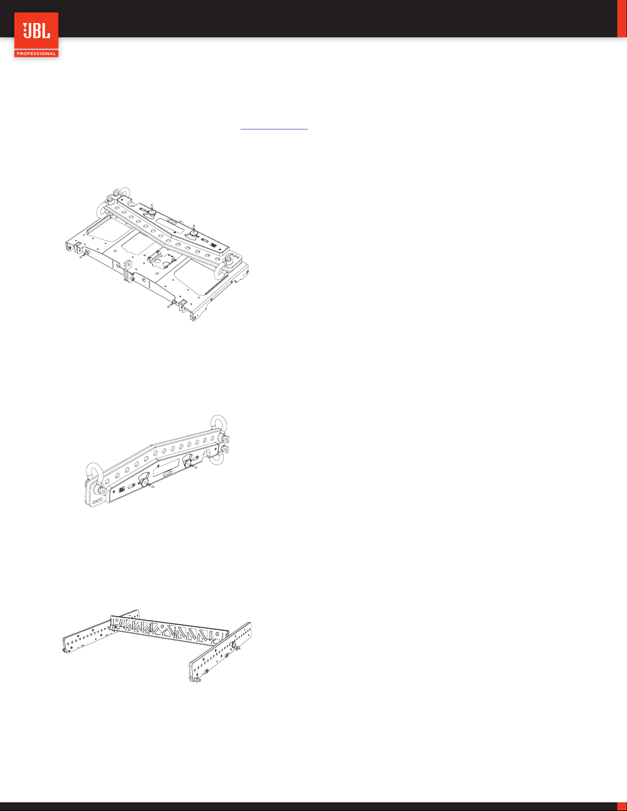
4.1 VTX A8 AF - ARRAY FRAME
• Compatible with VTX A8 and VTX B18
• Maximum Limit: (24) VTX A8 / (13) VTX B18
• 0.5 degree pick-point resolution
• Built-in storage position for extension bar
• Includes (1) VTX A8 AF EB extension bar
• Support for third-party laser inclinometers
• Compatible shackle size: 5/8 in
4.2 VTX A8 AF EB - ARRAY FRAME EXTENSION BAR
• Extension Bar for use with VTX A8 AF
• Single, front-to-back or side-by-side pick point options
• Includes (3) shackles and mounting brackets
• Compatible shackle size: 5/8 in
4.3 VTX A8 MF - MINI FRAME
• Compatible with VTX A8 and VTX B18
• Maximum Limit: (10) VTX A8 / (4) VTX B18
• Single-point and side-by-side pick-point options
• Three-part collapsible design
• Compatible shackle size: 1/2 in
11
Page 12
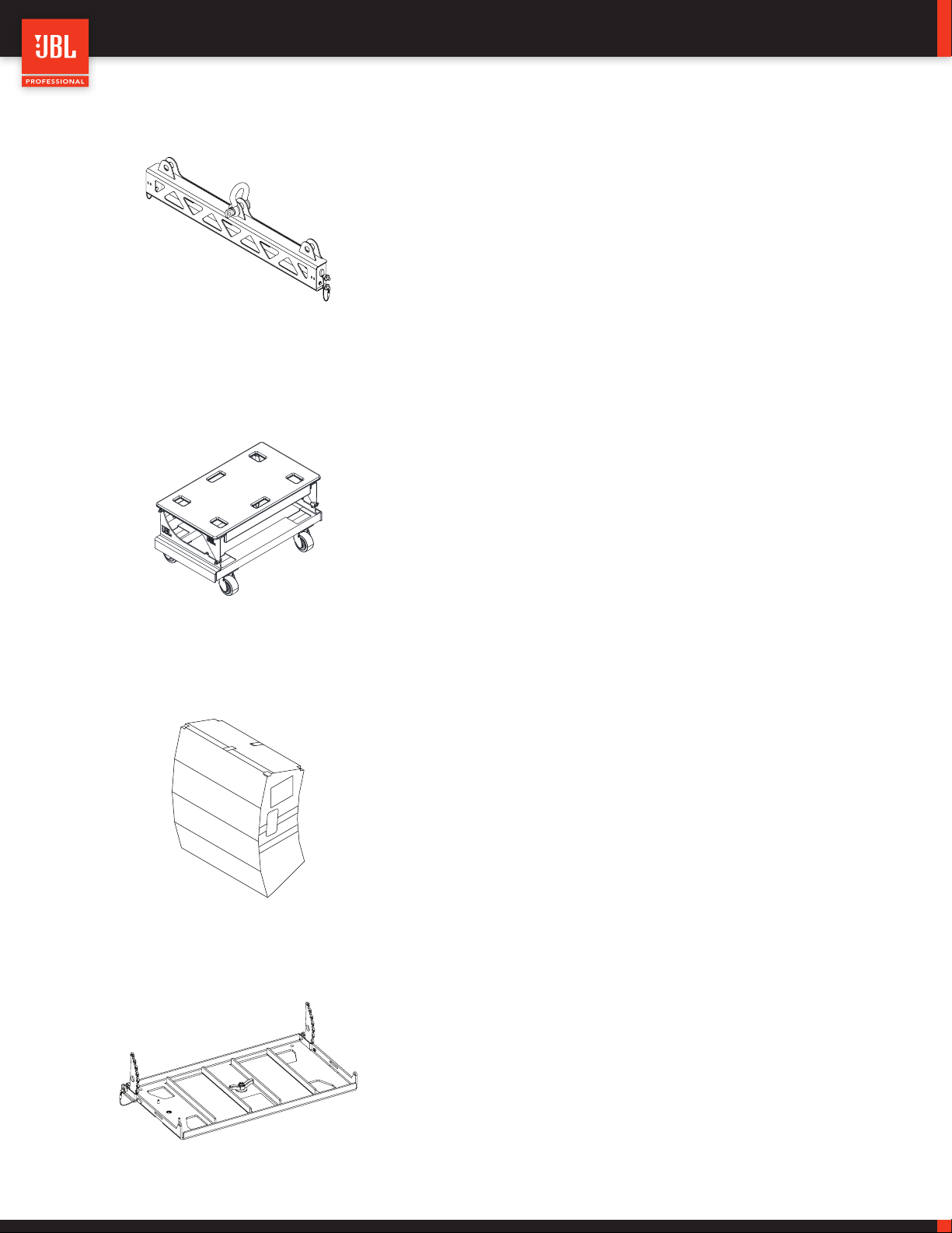
4.4 VTX A8 SB - SUSPENSION BAR
• Compatible with VTX A8 and VTX B18
• Maximum Limit: (24) VTX A8 / (16) VTX B18
• Used for pull-back applications
• Shackle Size: 5/8 in
4.5 VTX A8 VT - VERTICAL TRANSPORTER
• Vertical transport cart for (4) VTX A8 enclosures
• Truck-friendly dimensions
VTX A8 | User Manual
4.6 VTX A8 VT CVR - SOFT COVER
• Includes a hard top (VT-TOP)
• Built-in stacking features for easy storage
• Heavy-duty casters
• Heavy-duty soft cover for VTX A8 enclosures
• Covers four VTX A8 enclosures on a VTX A8 VT
• Includes input panel flaps for testing purposes
• Clear see-through pocket for shipping labels
• Handle cutouts for easy transportation
• Folds and stores in the VTX A8 VT
4.7 VTX A8 BP - BASE PLATE
• Used for ground stacking VTX A8
• Maximum Limit: (8) VTX A8 cabinets
• Connects VTX A8 cabinets to subwoofers
• Universal M20 attachment method
• Tilt range: -15 degrees to +5 degrees
12
Page 13

4.8 VTX RC500 - ROTATING CLAMP
4.9 VTX DELTA - DELTA PLATE
VTX A8 | User Manual
• Universal truss/pipe clamp adapter
• Working Load Limit: 500 kg (1,100 lbs)
• Adjustable clamping mechanism
• Pipe range: 1 – 2.0 in
• Includes bearing for smooth 360-degree rotation
• 10-degree rotation marks for horizontal array aiming
• Universal delta plate accessory for VTX systems
• Allows for +/- 10 degree horizontal adjustments
• Includes three 5/8 in shackles
• Working Load Limit: 2,177 kg (4,800 lbs)
TIP: For subwoofer-specific accessories, refer to the subwoofer user and rigging manuals found at www.JBLpro.com.
CAUTION: Always use components and accessories specified and approved by JBL Professional. When a cart is
used, use caution when moving the cart to avoid injury from tip-over.
13
Page 14

5 - SOFTWARE
VTX A8 | User Manual
5.1 LINE ARRAY CALCULATOR 3 TM
LAC is simulation software for designing and predicting VTX Se-
ries systems. LAC predicts the acoustical performance of line array
systems, as well as flown and ground-stacked subwoofer arrays.
Subwoofer delay values can be generated for electronic delay
steering (EDS) using the built-in coverage calculator. LAC also per-
forms mechanical validation of rigging hardware, calculates weight
limits, and generates safety warnings.
www.jblpro.com/lac3
5.2 ARRAY LINK TM
Array Link is a mobile companion app that works in conjunction
with LAC software to assist in deployment of VTX Series systems.
Array Link uses a QR code system to transfer all mechanical ar-
ray information from the main LAC application to a mobile phone.
All relevant rigging and mechanical options are presented in an
easy-to-understand layout. The application is compatible with
iOS® and AndroidTM and can be obtained from their respective app
stores.
5.3 PERFORMANCE MANAGER TM
Performance Manage is a configuration and control application for
networked audio systems. Performance Manager’s user interface
guides system designers through the complete system design,
configuration, and control processes. A dedicated show mode
provides all monitoring and control functions needed to deliver a
complete picture of the system’s performance in real time.
www.jblpro.com/performancemanager
14
Page 15

6 - INTRODUCTION
6.1 VTX A8
VTX A8 | User Manual
The VTX A8 is a next-generation line array element that delivers JBL Professional’s flagship VTX A Series technology in a compact solu-
tion for small to mid-size rental and installed applications. The VTX A8 was designed to solve the diverse sound reinforcement needs
of production companies, rental houses, theaters, houses of worship, as well as production applications requiring front fills, side arrays
or other auxiliary support for larger-scale VTX systems. Proprietary woofers and our latest-generation high-frequency transducer and
waveguide technology, provide unmatched performance, efficiency, and a consistent 110-degrees of horizontal coverage. The A8 com-
bines two 8-inch woofers, four 3.5-inch midrange drivers and two 2-inch high frequency drivers in a single low-profile cabinet. Propri-
etary double-flared low frequency ports, precisely calculated for greater low frequency performance extend the usable operating range
down to 49 Hz. The VTX A8 shares the VTX A Series’ patented rigging mechanism and suspension system for streamlined deployment,
while a comprehensive suite of accessories open up a world of configuration options.
INSIDE THE INNOVATIONS
For VTX A8, transducers were engineered from the ground up by JBL
to match the physical characteristics of its compact enclosure. Cus-
tom-designed low and mid frequency sections along with flagship
VTX A-Series two-inch compression drivers deliver higher output,
lower distortion and greater low frequency extension. Physical de-
sign refinements integrate more drivers in a smaller, lighter cabinet,
for maximum output in a dramatically reduced footprint. It all adds
up to big-system JBL sound in a flexible, compact line array system.
INNOVATIVE RIGGING
The VTX A8 rigging is identical to the A12 rigging, for quick,
easy deployment of integrated systems. The rigging features
an auto-locking mechanism, which allows the selection of an-
gles while components are on the ground; once the system is
suspended, the mechanism automatically locks cabinet angles
in designated positions. Set angles simply by pulling and plac-
ing a pin—it’s that easy.
3-WAY, 2-CHANNEL DESIGN
The VTX A8 features a three-way design, but utilizes a passive net-
work to drive both the MF and HF sections with a single amplifier
channel. Reducing system amplifier count translates to simpler con-
figuration, less total weight and truck space, and lower overall costs.
ACCESSORIES
Multiple accessory options provide flexibility in the VTX A8’s
mounting, integration and installation capabilities. Highlights
include a Base Plate that mounts the A8 on top of ground-
stacked subwoofers such as the new B18. The truss clamp
and mini frame enable the A8 to be mounted on a truss, mak-
ing it ideal for trade shows or small productions.
15
Page 16

6.2 VTX B18
VTX A8 | User Manual
The VTX B18 is JBL Professional’s single 18-inch subwoofer, designed to complement VTX full-range sound reinforcement systems. The
VTX B18 features JBL’s 2288H 18-inch woofer, engineered for improved linearity, increased sensitivity and extra-long excursion. The
2288H is based on JBL’s Differential Drive, dual voice coil, dual gap technology, which delivers better heat dissipation, lower power com-
pression, and wider dynamic range than conventional single-coil designs. The B18 incorporates a patented Slip Stream™ double-flared
exponential low frequency port design to improve airflow and reduce audible turbulence, even at maximum excursion. The B18 shares
the industrial design of the VTX A-Series products and has the same width and suspension hardware as the VTX A8, allowing the two
products to be used together in a variety of flown or ground stacked configurations. B18 subwoofers can be deployed in omnidirectional
or cardioid arrays, ground stacked, or in suspended configurations of up to 16 enclosures.
TRANSDUCER DESIGN
The VTX B18 features a JBL 2288H 18-inch high-performance woof-
er engineered from the ground up to deliver transparent, linear bass
response down to 28 Hz. The 18-inch driver leverages a patented
fourth-generation Differential Drive technology to deliver maximum
sensitivity and power handling in a light, compact design.
CONTROLLABLE COVERAGE
The B18 makes it simple to form omnidirectional or cardioid
arrays. Speaker connectors are available on both front and
rear panels, streamlining cable management in either config-
uration. A switch on the rear input panel allows for selecting
between channel 1 or 2 of the NL4 cable, minimizing cable
requirements.
VTX A8 COMPATIBILITY
The B18 rigging system is compatible with the VTX A8 rigging sys-
tem, allowing B18 subwoofers to be suspended above an A8 array.
The VTX B18 rigging system allows for omnidirectional or cardioid
configurations in small and large-scale flown or ground-stacked ar-
rays. All VTX A8 suspension accessories are compatible and arrays
of up to 16 enclosures can be created.
VTX BUILD QUALITY
The VTX B18 adopts the VTX A-Series’ signature full-face grill
design, which minimizes exposed components and protects
the loudspeaker from extreme conditions. The enclosed grill
helps the system achieve a higher Ingress Protection (IP55)
rating.
16
Page 17

VTX A8 | User Manual
7 - CONNECTIONS
The JBL VTX A8 is equipped with two Neutrik NL4 speakON connectors. The NL4 connectors are wired in parallel and can be used as
the system input or as a through connection for daisy-chaining multiple cabinets together. The NL4 connectors are installed upside
down so that the locking pin position can be seen from under the array.
NL4 Connectors : IN/OUT
A8
Compact Dual 8” Line Array Element
PINOUT
Pin 1
LF
Pin 2
MHF
IN/OUT IN/OUT
Designed in Los Angeles, CA
Made in Mexico
The VTX B18 is equipped with four Neutrik NL4 speakON connectors, two at the rear for the cabinet and two at the front grill. All four NL4
connectors are wired in parallel and can be used interchangeably. The NL4 connectors at the front of the B18 are typically used when
the B18s are setup in a cardioid configuration, where some of the enclosures are pointed backwards. All NL4 connectors are installed
upside down so that the NL4 locking pin position can be seen from under the array.
Rear NL4 Connectors : IN/OUT
B18
Compact Single 18” Subwoofer
IN/OUT IN/OUT
SN
A
B
Channel Selection
Front NL4 Connectors : IN/OUT
Channel Selection Switch
A channel selection switch is available at the rear of the B18, which selects between Pin 1 and Pin 2 of the NL4 connector. The switch is
wired after the NL connectors and affects all connections equally. For more information on the B18, refer to the VTX B18 User Manual.
CAUTION: Always use high-quality insulated speaker cables made by reputable manufacturers. Keep cable length
as short as possible with sufficient gauge for the application.
17
Page 18

7.1 A8 INTERNAL WIRING
NL4
1+
1-
2+
2-
1+
1-
2+
2-
Passive Network
VTX A8 | User Manual
LF
MF / HF
7.2 B18 INTERNAL WIRING
FRONT NL4 REAR PANEL NL4
1+
1-
2+
2-
MF
1+
1-
2+
2-
Pin Selection
Switch
A B
HF
SUB
1+
1-
2+
2-
1+
1-
2+
2-
18
Page 19

VTX A8 | User Manual
8 - SYSTEM AMPLIFICATION & WIRING
Like all other VTX systems, the VTX A8 and B18 cabinets are powered exclusively by Crown I-Tech HD amplifiers, providing consisten-
cy and optimum performance anywhere in the world. All speaker processing is performed using the I-Tech HD’s internal processing,
which includes the advanced LevelMaxTM three-stage limiter suite, ensuring proper, reliable operation under any conditions. LevelMax
incorporates excursion control, RMS limiting, and long-term thermal protection for the transducers. The I-Tech HD amplifiers also offer a
user-adjustable input section for equalization, time alignment, and electronic delay steering. Standard JBL presets are available for both
the Crown I-Tech 4x3500HD and I-Tech 12000HD. The most up-to-date presets are available for download from www.jblpro.com, and
bundled in the latest version of Performance Manager control software.
8.1 USING A8 WITH CROWN I-TECH 4X3500HD
When using Crown I-Tech 4x3500HD amplifiers, up to six VTX A8 loudspeakers (three per circuit) can be powered per amplifier. Based
on the power demands of the A8, this allows for optimum power-to-transducer ratio without compromising the maximum SPL capabil-
ities of the system. Circuits with two cabinets can be used to create smaller coverage areas in the venue for finer control. The example
below illustrates how to connect six VTX A8 cabinets to an I-Tech 4x3500HD amplifier using standard four-contact NL4 cables.
Amplifier Rear Panel
CH1/CH2CH1/CH2 CH3/CHCH3/CH44
OUTPUTSOUTPUTS
NL4 Cables
Crown I-Tech 4x3500HD (6) VTX A8
Amplifier Channels
Channel 1 A8 LF
Channel 2 A8 MF/HF
Channel 3 A8 LF
Channel 4 A8 MF/HF
19
Page 20

VTX A8 | User Manual
Standard NL8 cables can be used to connect VTX A8 cabinets to a Crown I-Tech 4x3500HD amplifier using an NL8-to-two-NL4 break-
out cable. Using this breakout cable, up to six VTX A8 cabinets can be connected to a four-channel amplifier using a single NL8 cable,
saving cables and simplifying wiring.
Crown I-Tech 4x3500HD
Amplifier Rear Panel
CH1/CH2CH1/CH2 CH3/CHCH3/CH44
OUTPUTSOUTPUTS
NL8 Cable
(6) VTX A8
8.2 USING A8 WITH CROWN I-TECH HD (2-CH)
When using Crown I-Tech HD amplifiers (two-channel), up to three VTX A8 loudspeakers can be powered per amplifier. One channel is
used for powering the low frequency section and another for the mid and high frequency sections. Based on the power demands of the
A8, this allows for optimum power-to-transducer ratio without compromising the system’s maximum SPL capabilities. Circuits with two
cabinets can be used to create smaller coverage areas in the venue for finer control. The example below illustrates how to connect three
VTX A8 cabinets to a two-channel I-Tech HD amplifier using a standard four-contact NL4 cable.
Amplifier Rear Panel
Amplifier Channels
Channel 1 A8 LF
Channel 2 A8 MF/HF
NL4 Cable
(3) VTX A8Crown I-TECH HD
20
Page 21

VTX A8 | User Manual
8.3 USING A8 AND B18 WITH I-TECH 4X3500HD
A8 and B18 products can be combined on a single I-Tech 4x3500HD amplifier. In this case, the amplifier has enough resources to power
four B18 subwoofers and up to three A8 cabinets without compromising SPL or the long-term thermal capabilities of the amplifier.
Channel Selection
Switch
Amplifier Channels
Channel 1 B18 1 & 2
Channel 2 B18 3 & 4
Channel 3 A8 LF
Channel 4 A8 MHF
Amplifier Rear Panel
CH1/CH2CH1/CH2 CH3/CHCH3/CH44
OUTPUTSOUTPUTS
A
A
A B
A B
B
B
Crown I-Tech 4x3500HD
(4) VTX B18
(3) VTX A8
CAUTION: Attempting to drive more than four B18 enclosures from a single 4X3500HD is not recommended and
may degrade performance and compromise long-term thermal capabilities of the amplifier.
21
Page 22

VTX A8 | User Manual
8.4 USING A8 AND B28 WITH I-TECH 4X3500HD
When using Crown I-Tech 4x3500HD amplifiers, up to two VTX B28 subwoofers can be powered per amplifier and the remaining chan-
nels can be used to power a JBL full-range speaker, such as the VTX A8. The example below illustrates how to connect two VTX B28
cabinets and three VTX A8 to a four-channel I-Tech HD amplifier. A cable breaking the NL4 connector out to two NL2 connectors can
be used to drive one B28 each from amplifier channels 1 and 2. A four-conductor NL4 cable is employed in this arrangement, reducing
cabling requirements. Amplifier channels 3 and 4 remain available for driving a full-range product, such as the VTX A8.
Amplifier Rear Panel
CH1/CH2CH1/CH2 CH3/CHCH3/CH44
OUTPUTSOUTPUTS
NL4 Cable
I-Tech 4x3500HD
Amplifier Channels
NL4 Cable
(2) VTX B28
Channel 1 B28 1
Channel 2 B28 2
Channel 3 A8 LF
Channel 4 A8 MHF
(3) VTX A8
CAUTION: Attempting to drive more than two B28 enclosures from a single 4X3500HD is not recommended and
may degrade performance and compromise long-term thermal capabilities of the amplifier.
8.5 CROWN V-RACK
VTX Series systems are compatible with the Crown V-Rack 12000HD and Crown V-Rack 4x3500HD touring racks. The number of cab-
inets supported by each amplifier and the wiring options remain the same as the Crown I-Tech examples illustrated in this document.
For more information on Crown V-Rack products, refer to the V-Rack User Manual and documentation.
22
Page 23

VTX A8 | User Manual
9 - VTX A8 PRESET LIBRARY
The VTX A8 preset library includes standard array and fill (FL) operating modes, along with full-range and 80 Hz low frequency process-
ing modes. VTX presets are exclusively developed for Crown I-Tech HD amplifiers and come bundled with Performance Manager control
software. Audio ArchitectTM presets are also available and can be downloaded from www.jblpro.com. Below is a detailed description of
VTX A8 operating modes and subwoofer processing options. Refer to the Preset Library setup sheets for preset descriptions, memory
locations and output channel assignments.
9.1 VTX A8 PRESET MODES AND OPTIONS
Two preset modes and two low frequency processing options are available:
VTX A8 FL: The FL presets (short for FILL) have nominally flat frequency response and are to be used in situations where one or two A8
cabinets are appropriate, such as distributed front fills. With this preset, the acoustical low frequency response of the system extends
down to 49 Hz (full range).
VTX A8 FL 80: The FL 80 presets have nominally flat frequency response and are to be used in situations where one or two A8 cabinets
are appropriate, such as distributed front fills. With this preset, the acoustical low frequency response of the system is set to 80 Hz and
used when subwoofers are available.
VTX A8: This is the standard VTX A8 preset for array use. A high frequency shelving response is applied to offset LF/MF array buildup
for nominally-focused arrays (equally spaced impact points over the desired audience coverage area). With this preset, the acoustical
low frequency response of the system extends down to 49 Hz (full-range).
VTX A8 80: This is the standard VTX A8 preset for array use with subwoofers. A high frequency shelving response is applied to offset
LF/MF array buildup for nominally focused arrays (equally spaced impact points over the desired audience coverage area). With this
preset, the acoustical low frequency response of the system is set to 80 Hz. The VTX A8 80 preset will generate the highest A-weighted
maximum sound pressure level.
9.2 VTX B18/B28 PRESET MODES AND OPTIONS
VTX BXX 60: The 60 Hz preset mode extends the upper frequency response of the subwoofer to 60 Hz. The 60 Hz preset is normally
used when VTX cabinets (like the A8 or A12) are used in full-range mode.
VTX BXX 60 REAR: The 60 Hz rear preset was designed to work in conjunction with the standard 60 Hz preset to drive rear-facing B18
cabinets in cardioid configurations.
VTX BXX 80: The 80 Hz preset mode extends the upper frequency response of the subwoofer to 80 Hz. The 80 Hz preset is normally
used when VTX full-range cabinets (like the VTX A8 or A12) are set to 80 Hz.
VTX BXX 80 REAR: The 80 Hz rear preset was designed to be work in conjunction with the standard 80 Hz preset to drive rear-facing
B18 cabinets in cardioid configurations.
TIP: The VTX A8 presets provide a well-balanced tonal starting point for a given array size. The Array Size Compensation
filter found in the JBL Line Array Control Panel (LACP) can be used to further fine-tune the tonal balance of an array for a
given size and shape. Please refer to the LACP section for more information.
23
Page 24

VTX A8 | User Manual
Frequency (Hz)
SPL (dB)
20
10 - SUBWOOFER OPTIONS
VTX A8 presets are designed for a 3:2 minimum cabinet ratio when used with the VTX B18, and a 3:1 ratio when used with dual 18-inch
subwoofers like the VTX B28, G28 or VTX S28. The minimum recommended ratios provide sufficient headroom for both the subwoofers
and the full-range cabinets to reach MAX SPL (limiters) at the same time, while maintaining a minimum of 10 dB SUB to full-range low
frequency contour. Other ratios can be used depending on the desired tonal balance target, MAX SPL and application.
VT X A8 VT X B18 VT X B28
10.1 SUB / LF PRESET OPTIONS
As previously mentioned, there are two LF presets available for the A8 system: one is the VTX A8 (full-range) preset, which extends the
frequency response of the system down to 49 Hz; the other is the VTX A8 80 (80 Hz) preset, which extends the frequency response of the
system down to 80 Hz. The VTX A8 (full-range) preset is used when the system is operated without subwoofers or when the application
calls for extended LF response from the main arrays. The VTX A8 80 (80 Hz) preset is used only when subwoofers are available and when
the highest A-weighted sound pressure level (SPL) is required. When multiple A8 arrays are used (i.e. main and side arrays), all VTX A8
arrays should be operated in the same LF mode for headroom consistency.
Example 1: A8 80 | SUB: 80 Example 2: A8 FR | SUB: 60 or 80
20
10
10
SUB: 80Hz
0
SPL (dB)
-10
-20
20 100 1000
Frequency (Hz)
24
0
-10
-20
20 100 1000
SUB: 60Hz
Page 25

VTX A8 | User Manual
10.2 TIME ALIGNMENT
The VTX A8 presets provide proper system summation with companion VTX subwoofers (all models) in physically coupled configura-
tions (stacked or suspended), and when used with corresponding subwoofer presets. This pre-alignment is done at the factory, allowing
any VTX subwoofer to be used with other VTX products without needing specific subwoofer presets for each system and configuration.
VTX A8 VTX B18 VTX B28
Additional time alignment delay should be added, as necessary, to account for physical path length differences between suspended
A8 arrays and ground-stacked VTX subwoofers. If no acoustic measurement system is available, delay values can be calculated based
on the geometric path difference between a reference point (i.e. FOH position) and each system. This is an effective method, since all
VTX presets include a factory pre-delay to correctly align all components. When the latency of a system is unknown, this method is not
effective and should not be used. This can occur when the signal paths of different parts of the system vary in latency.
Path Difference = dFlown Array - dSub
Sub Delay =
Path Diff
Sub Delay =
dFlown Array
dSub
Path Difference (meters)
343 (meters / second)
or
Path Difference (feet)
1140 (feet / second)
25
dSub
Page 26

11 - CONFIGURATION EXAMPLES
11.1 SMALL A8 SYSTEM
VTX A8 | User Manual
11.2 MEDIUM A8 SYSTEM
26
Page 27

11.3 LARGE A8 SYSTEM
VTX A8 | User Manual
11.4 LARGE A8 AND A12 SYSTEM
27
Page 28

VTX A8 | User Manual
12 - FREQUENCY RESPONSE
The frequency response of a line array is determined by many factors, including the array size (number of cabinets), array curvature
(cabinet-to-cabinet angles) and the listening distance. JBL factory presets are designed to create a well-balanced tonal starting point
for a given set of array conditions. For example, the standard VTX A8 array presets are designed to work optimally with arrays of 8-12
cabinets and equal impact spacing for a flat listening plane. An array with these parameters generates a flat HF frequency response with
a gradual increase in LF energy. The frequency at which the response starts rising depends on the array parameters mentioned above.
A relatively short array will start rising lower in frequency, while a longer array starts rising at a higher frequency. Below are frequency
response examples of A8 arrays using the standard VTX A8 presets and no additional equalization/correction (flat).
Example 1 : A8 Frequency response vs number of cabinets
20
Frequency response of a 12-cabinet A8 array
10
0
SPL (dB)
-10
-20
20 100 1000 10000 20000
Frequency (Hz)
Example 2: Standard preset vs 80 Hz preset
20
10
0
SPL (dB)
-10
-20
20 100 1000 10000 20000
Frequency (Hz)
Frequency response of an eight-cabinet A8 array
Frequency response of a six-cabinet A8 array
Frequency response of a four-cabinet A8 array
Frequency response of a 12-cabinet A8 array
Frequency response of a 12-cabinet A8 array using the 80
Hz preset
Since the factory preset cannot account for all variables and array configurations, user adjustment of certain DSP parameters is neces-
sary to achieve the desired tonal balance for a given array and application. The LF response of any VTX line array system can be easily
adjusted using the Array Size Compensation Filter in the JBL Line Array Control Panel. The Array Size Compensation Filter was specif-
ically designed to compensate for LF/MF buildup with a single, adjustable parameter. Lowering the gain value of this filter shifts lower
the frequency at which LF response starts rising— similar to the behavior when array length is shortened.
28
Page 29

13 - LINE ARRAY CONTROL PANEL
VTX A8 | User Manual
The JBL Line Array Control Panel (LACP) was designed to tailor
the tonal balance of a line array using the five included, adjust-
able, DSP filters. Each filter serves a specific, intended purpose
and accelerates the tuning process. Two of these filters are global
adjustments grouped across the entire array, and three filters are
for circuit-specific adjustments. LACP parameters can be mod-
eled using the Line Array Calculator and then applied to amplifiers
in real time using Performance Manager control software.
13.1 ACCESSING LACP
LACP filters can be modeled in the Line Array Calculator 3 and then imported into Performance Manager for deployment to actual de-
vices. To access LACP within the Line Array Calculator, first use LAC’s grouping features to create circuit groups. The groups should
represent the actual array amplification and wiring to enable realistic and accurate DSP adjustments. Click on the LACP button next to
any circuit group to edit it.
29
Page 30

VTX A8 | User Manual
13.2 FILTER 1 - ARRAY SIZE COMPENSATION
Filter 1 is used to correct for LF/MF buildup when the array size or shape differs from that for which the factory preset was designed. LF
adjustments should be applied to all cabinets within the array; therefore, filter 1 is automatically applied globally. Filter 1 is a continuously
variable LF shelving filter, and its parameters (corner frequency and slope) are adjusted based on the applied gain value. Array buildup
is different for each configuration, and Filter 1 is optimized to correct for this effect using only one parameter (Gain).
13.3 FILTER 2 - ATMOSPHERIC ABSORPTION COMPENSATION
Filter 2 is used to compensate for large variations in temperature and humidity, which can have an impact on overall HF energy. Filter 2 is
applied globally and can be used to quickly brighten or darken an array. This filter can also be used for artistic purposes to adjust overall
system tonal balance. The result of atmospheric changes can be modeled in LAC by adjusting the temperature and humidity controls.
13.4 FILTER 3 - HF THROW DISTANCE COMPENSATION
Filter 3 is typically used to correct for distance offsets between different sections of an array. The Type, Frequency and Q parameters are
linked across the entire array, but the Gain parameter is adjustable per circuit group. This filter can be used to reduce HF energy close
to an array and increase HF energy to areas further away, where air absorption has a bigger impact.
13.5 FILTERS 4 & 5 - USER PEQ 1 & 2
Filters 4 and 5 are User parametric EQs, which can be applied to individual circuit groups as needed. The Frequency and Q parameters
are not linked across circuits and, for this reason, it is recommended that User PEQ 1 & 2 are used only for moderate gain changes of
frequencies above 1kHz. In this range, the directivity of the high frequency waveguides is narrow enough that changes done to one
circuit group will have minimal effects in other areas of the venue.
30
Page 31

VTX A8 | User Manual
13.6 EXAMPLE USING LACP
This example is for an array of 12 VTX A8 cabinets. The standard A8 preset is used with the Array Size Compensation filter set to –3 dB
to offset LF buildup and achieve a flatter frequency response. As seen from the illustration below, Array Size Compensation is globally
applied to all array circuits. The bottom circuit includes some attenuation from HF Throw Distance Compensation (Filter 3) to correct
for proximity differences. Some simple adjustments to the LACP filters will get an A8 system to a very good staring point. The need for
further adjustments will be dependent on the room and the specific application.
TIP: The LACP parameters used in LAC to predict an array can be easily deployed to an actual array in Performance
Manager. For information on how to import LACP parameters into Performance Manager, please refer to the Performance
Manager documentation.
31
Page 32

VTX A8 | User Manual
14 - TESTING THE VTX A8
Speakers need to be periodically checked and maintained to assure long-term performance and reliability. While the VTX A8 is designed
for the utmost reliability, it is important to confirm that the system is operating within specified tolerances to ensure optimal performance
for years to come. Below are two methods that can be used to check and verify proper transducer performance in a VTX A8 system.
14.1 USING A DMM (DIGITAL MULTI METER)
This method is best suited for when the speaker system is in the shop. A DCR (DC resistance) test with a multimeter can give a very
accurate reading of how many transducers are properly wired together and within their standard operating tolerances. This test is ap-
propriate for individual cabinets and not groups.
With the A8 speaker unconnected to any amplifiers, set a DMM to the resistance (Ω) setting and place the probes across the Pin1+/- and
Pin 2+/- leads. Record the values indicated on the DMM for each pair of leads and refer to the chart below to either confirm correct read-
ings or investigate out-of-tolerance DCR readings. Note that a passive network is used between the MF and HF sections, so any major
deviations from the values listed below should be further examined by removing the input panel and testing the individual components.
A8 MF/HF Section (Pin 2)
DCR Tolerance
All drivers functioning 6.5 Ω +/- 0.2 Ω
Any driver shorted 0.2 Ω -
A8 LF Section (Pin 1)
DCR Tolerance
All woofers functioning 5.2 Ω +/- 0.2 Ω
One woofer open 10.1 Ω +/- 0.2 Ω
Two woofers open OL -
Any driver shorted 0.2 Ω -
B18
DCR Tolerance
B18 functioning 4.5 Ω +/- 0.2 Ω
Driver shorted 0.2 Ω -
Compact Dual 8” Line Array Element
IN/OUT IN/OUT
Designed in Los Angeles, CA
Made in Mexico
A8
PINOUT
Pin 1
LF
Pin 2
MHF
NOTES:
• The DCR values listed above assume room temperature transducers. If measurements are taken right after use, when the transduc-
ers are warm, the values will vary. For best results, test the speakers cold.
• The DCR value of a transducer gives an accurate representation of its electrical state, but mechanical defects are not characterized
by this test. Refer to the VTX A8 Service Manual for instructions on performing a rub-and-buzz test with a sine wave generator.
32
Page 33

VTX A8 | User Manual
14.2 TESTING INDIVIDUAL COMPONENTS
Testing the individual sections of an A8 enclosure requires removing the input panel and bypassing the passive network. Remove the
(10) T15 screws holding the panel, then slide the input panel out of the A8 enclosure. Once the panel has been removed, disconnect the
MolexTM connector from the board as illustrated below.
The MolexTM connector has 12 pins that can be used with a DMM to test the individual sections of the A8 speaker. The pin assignments
of the Molex connector are listed below. Note that the locking tab of the connector should be oriented face up. Insert the DMM test leads
into the pins to take the measurements. The DCR values of each section should be within the given tolerances of the values listed below.
Since each pair of MF transducers is wired in series, if an open (overload) is measured, one or both of the transducers might be defective.
Pins Section DCR Tolerance
Pins 1 & 2 LF Right 10.1 Ω +/- 0.2 Ω
Pins 7 & 8 LF Left 10.1 Ω +/- 0.2 Ω
Pins 3 & 4 MF Right 12 Ω +/- 0.2 Ω
Pins 9 & 10 MF Left 12 Ω +/- 0.2 Ω
Pins 5 & 11 HF 1 20 Ω +/- 0.2 Ω
Pins 6 & 12 HF 2 20 Ω +/- 0.2 Ω
7 8
1 2
9 10 11 12
3 4 5 6
TOOLS REQUIRED: A size 15 TORX screwdriver is required to remove the screws holding the input panel on the A8 en-
closure. A high-quality digital multimeter is required for measuring the transducers.
33
Page 34

VTX A8 | User Manual
14.3 USING PERFORMANCE MANAGER
When in the field, the Test System Mode in the Performance Manager software can be used to test an A8 system. This test method is
quick and especially useful for determining whether all speaker cables, including cabinet-to-cabinet NL jumpers, are properly function-
ing.
To perform the test, Performance Manager uses the I-Tech HD’s built-in noise generator in conjunction with the amplifier’s current draw
and voltage sensing capabilities to generate a nominal load impedance reading for each amplifier output channel. Since broadband pink
noise is used as the test stimulus, the returned value is considered to be an impedance value, and it will differ from the resistance values
given earlier in this document (which are taken using DC voltage as the stimulus). `
STEPS:
1
• Make sure Performance Manager is online and connected to the devices.
2
• Navigate to the Test System Mode and make sure all speakers are muted.
3
• Switch the Noise Generator to the ON position and change the level to a value between -30 dB and -10 dB. Values lower than
-30 dB may be insufficient to trigger a reading.
4
• Unmute the speaker or a bandpass to start the measurement. The measured value is displayed on the speakers.
13.4 PERFORMANCE MANAGER READINGS
Below are the expected impedance values for circuits of A8 cabinets. The measurements below were taken at room temperature with a
cable length of 25 m (82 ft). Acceptable tolerance is +/- 0.5 Ω.
1 x VTX A8 2 x VTX A8 3 x VTX A8 4 x VTX A8
Variances in temperature, cable length, wire gauge and usage can make the measurements recorded by Performance Manager more
susceptible to drift. However, variations in conditions like temperature are common across all similar circuits of a system. More important
than the individual component values is consistency across similar circuits. For example, all three-cabinet circuits for an array should
measure similarly. If one is off by several ohms, there is likely something wrong with that specific circuit.
34
Page 35

15 - SPECIFICATIONS
SYSTEM
Frequency Range (-10 dB):
49 Hz - 19 kHz (Preset: VTX A8)
VTX A8 | User Manual
Coverage Pattern (-6 dB)
Horizontal:
Vertical:
System Input Power Rating
LF :
MF/HF :
Maximum Peak Output²:
System Amplification:
Required Amplifier Channels:
Number of Cabinets per Circuit:
System Impedance
LF :
MF/HF :
TRANSDUCERS
Low Frequency :
Mid Frequency :
High Frequency :
110 degrees nominal (300 Hz-18 kHz)
Varies with array size and configuration
1
600 W Continuous (IEC/100 hour)
390 W Continuous (IEC/100 hour)
139 dB (Preset: VTX A8)
Crown I-Tech HD (all models)
Crown I-Tech 4x3500HD
Two-Channels, Bi-Amp (LF|MHF)
(3) VTX A8
8 ohms
8 ohms
(2) JBL 258J, 8 in diameter, dual 2.5 in diameter voice coil, Neodymium Differential Drive®
(4) JBL 2163H, 3 in diameter, 1.5 in diameter voice coil, Neodymium magnet
(2) JBL 2423K, 2 in diameter annular diaphragm, 2 in diameter voice coil, Neodymium compression drivers
ENCLOSURE
Construction :
IP Rating3 :
Suspension :
9 mm 9-ply Finnish birch plywood, black DuraFlexTM finish, four integral recessed handholds
IP55 (IEC 60529)
High-grade steel with anti-corrosion coating, captive suspension plates, quick release pins, auto-locking mechanism for setting angles
Inter-enclosure Angle :
0.25, 0.5, 1, 1.5, 2, 2.5, 3, 4, 6, 8, 10
Powder-coated 1.5mm (16-gauge) hex-perforated steel with acoustically transparent black cloth backing
Grill :
Connectors
Neutrik® speakON® NL4 (2)
Type :
Pin Assignments :
Dimensions (H x W x D) :
Pins 1 ± (LF), Pins 2 ± (MF/HF)
227 mm x 761 mm x 375 mm
8.9 in x 29.9 in x 14.7 in
Net Weight :
Footnotes:
1: IEC Standard: IEC shaped noise with 6 dB crest factor based on nominal impedance and a duration of 100 hours. Continuous is defined as 2x RMS
2: Peak, unweighted SPL, measured under full-space conditions at 1 meter using broadband pink noise with a 12 dB crest factor and specified preset
3: Front face at 0 degrees or greater down angle to allow the cabinet to drain water. Suspension components fully weather rated for indoor or covered outdoor conditions where humidity is nominally under 50% and not local
to bodies of corrosive materials. Unused speakON connectors must be sealed using silicone to protect against water and moisture.
JBL continually engages in research related to product improvement. Some materials, production methods and design refinements are introduced into existing products without notice as a routine expression of that
philosophy. For this reason, any current JBL product may differ in some respect from its published description, but will always equal or exceed the original design specifications unless otherwise stated.
29.5 kg (65 lbs)
35
Page 36

16 - ACOUSTIC MEASUREMENTS
Frequency (Hz)
20 180
VTX A8 | User Manual
FREQUENCY RESPONSE
10
0
SPL (dB)
-10
-20
20 100 1000 10000 20000
VTX A8 FL VTX A8 FL 80 VTX A8 Phase
17 - DIMENSIONS
90
0
-90
-180
BEAMWIDTH
360
100
10
20 100 1000 10000 20000
Horizontal Beamwidth (-6 dB)
227 mm (8.9 in)
761 mm (29.9 in)
375 mm (14.7 in)
36
Page 37

18 - CONTACT INFORMATION
UNITED STATES OF AMERICA
VTX A8 | User Manual
HARMAN Professional Solutions
8500 Balboa Blvd.
Northridge, CA 91329
USA
+1 (844) 776-4899
www.jblpro.com
PROFESSIONAL CONTACTS, OUTSIDE THE U.S.A.:
Contact the JBL Professional distributor in your area. A complete list of JBL Professional international distributors is provided at our
U.S.A. website: www.jblpro.com
HARMAN Professional EMEA
Westside
London Road
Hemel Hempstead
HP3 9TD
United Kingdom
www.pro.harman.com
www.jblpro.com/support
U.S.A. Technical Support
+1 (800) 852-5776
HProTechSupportUSA@Harman.com
www.jblpro.com
HARMAN Professional APAC
108 Pasir Panjang Road
#02-08 Golden Agri Plaza
Singapore 118535
+65 6870-5000
www.pro.harman.com
www.jblpro.com/support
HARMAN Professional China
20F, China Merchants Port Plaza, #1
Gongye 3rd Road, Shekou, Nanshan
Dist.
Shenzhen, 518067, China
400 166 7806
www.harman.com/China
HARMAN Professional India
Prestige Technology Park
Jupiter 2A Block, 4th Floor
Marathahalli Ring Road
Bangalore 560103, India
+1 (800) 208-8880
www.harman.com/India
India In-Country Support
www.harman.com/india/india-service-center
China In-Country Support
ChinaPRO.Service@harman.com
HARMAN Professional Brazil
Br386, Km435 92480-000
Nova Santa Rita Rs
Brazil
+55 51 34794000
www.harman.com/Brasil
www.jblaudio.com.br
Brazil In-Country Support
tecnica@harman.com
37
Page 38

 Loading...