

Page 1
VTX A12 | User Manual
Page 2

VTX A12 | User Manual
GENERAL INFORMATION
VTX A12 - User Manual
Document Number: 1000297494
Version: D - EN
Distribution Date: December 3, 2020
Copyright © 2020 by HARMAN International; all rights reserved
JBL PROFESSIONAL
8500 Balboa Blvd
Northridge, CA 91329
USA
Page 3
VTX A12 | User Manual
Thank you for purchasing JBL V TX Series products
In more than 75 years of JBL innovations, the VTX Series stands apart as a milestone in the practical application of cre-
ative engineering. VTX products herald the next generation in line array loudspeaker systems: a new era in performance,
system integration and user friendliness. VTX products draw on multiple JBL patents in driver, waveguide, and suspension
technology, as well as custom amplification, DSP, control, and system management designs created in collaboration with
HARMAN Professional sister companies.
VTX loudspeakers marry custom transducer design and in-house manufacture, breakthrough technologies, and a com-
prehensive system approach to deliver a premium experience for all who come into contact with it, from the FOH mixing
engineer to the systems engineer, rigger, road crew, warehouse manager, and, of course, the audience. Designed for
operators of portable and fixed systems alike, the VTX Series features JBL’s legendary sound quality coupled with expert
support and advanced tools that enable optimal specification, configuration, and operation of VTX systems in any venue,
anywhere in the world. The VTX Series delivers a comprehensive solution: the finest sound quality available, plus efficient
and intuitive setup, tuning, networking, and control.
Page 4

VTX A12 | User Manual
TABLE OF CONTENTS
1 - DECLARATION OF CONFORMITY ...........................................................................6
2 - SAFETY .................................................................................................7
2.1 Safety Instructions ....................................................................................7
2.2 General Hardware Information ..........................................................................7
2.4 Important Safety Warning ..............................................................................8
2.5 Are You New to Rigging? ..............................................................................8
2.6 Inspection and Maintenance ............................................................................8
2.7 Symbols ............................................................................................9
3 - SYSTEM COMPONENTS .................................................................................10
4 - COMPATIBLE ACCESSORIES ..............................................................................11
4.1 VTX A12 AF - Array Frame .............................................................................11
4.2 VTX A12 AF EB - Array Frame Extension Bar ..............................................................11
4.3 VTX A12 SB - Suspension Bar ..........................................................................11
4.4 VTX A12 VT - Vertical Transporter .......................................................................12
4.5 VTX A12 VT CVR - Soft Cover ..........................................................................12
4.6 - VTX A12 VT GND - Ground Stack Accessory .............................................................12
4.7 VTX Delta - Delta Plate ................................................................................12
4.8 VTX A12 BP - Base Plate ..............................................................................13
5 - SOFTWARE .............................................................................................14
5.1 Line Array Calculator 3TM ..............................................................................14
5.2 Array LinkTM ........................................................................................14
5.3 Performance ManagerTM ..............................................................................14
6 - INTRODUCTION .........................................................................................15
6.1 VTX A12/VTX A12W ..................................................................................15
6.2 VTX A12 vs VTX A12W ................................................................................16
6.3 Identifying A12 and A12W .............................................................................16
7 - CONNECTIONS .........................................................................................17
7.1 Internal Wiring ......................................................................................17
8 - SYSTEM AMPLIFICATION .................................................................................18
8.1 Using the A12 with Crown I-Tech 4x3500HD ...............................................................18
8.2 Using the A12 with Crown I-Tech 12000HD ................................................................19
8.3 Crown Audio V-Rack .................................................................................19
9 - VTX A12 PRESET LIBRARY ................................................................................20
9.1 VTX A12 Preset Modes and Options .....................................................................20
Page 5

VTX A12 | User Manual
10 - SUBWOOFER OPTIONS .................................................................................21
10.1 SUB/LF Preset Options ...............................................................................21
10.2 Preset Example 1 ...................................................................................22
10.3 Preset Example 2 ...................................................................................22
10.4 Time Alignment .....................................................................................23
11 - FREQUENCY RESPONSE ................................................................................24
12 - LINE ARRAY CONTROL PANEL ...........................................................................25
12.1 Accessing LACP ....................................................................................25
12.2 Filter 1 - Array Size Compensation .....................................................................26
12.3 Filter 2 - Atmospheric Absorption Compensation ..........................................................26
12.4 Filter 3 - HF Throw Distance Compensation ..............................................................26
12.5 Filters 4 & 5 - User PEQ 1 & 2 .........................................................................26
12.6 Example using LACP ................................................................................27
13 - TESTING VTX A12 ......................................................................................28
13.1 Using a DMM (Digital MultiMeter) ......................................................................28
13.2 Using Performance Manager ..........................................................................29
13.3 Performance Manager Readings .......................................................................29
14 - SPECIFICATIONS .......................................................................................30
14.2 VTX A12 Specifications ..............................................................................30
14.2 VTX A12W Specifications .............................................................................31
15 - ACOUSTIC MEASUREMENTS ............................................................................32
15.1 VTX A12 ..........................................................................................32
15.2 VTX A12W ........................................................................................32
16 - DIMENSIONS ..........................................................................................33
17 - CONTACTS INFORMATION ...............................................................................34
Page 6
1 - DECLARATION OF CONFORMITY
BRAND: JBL Professional
FAMILY NAME: VTX A12 loudspeaker and suspension accessories
MODEL NAMES:
VTX A12 | User Manual
• VTX A12
• VTX A12W
• VTX A12 AF
• VTX A12 AF EB
• VTX A12 SB
• VTX A12 VT
We, HARMAN International, declare under our sole responsibility that the product, to which this declaration relates, is in conformity
with the following standards:
STANDARD DESCRIPTION TEST AGENCY
2006/42/EC
MACHINERY DIRECTIVE
• VTX A12 VT GND
• VTX DELTA
Applies to machinery and lays down essential
health and safety requirements
ISO12100
Tested at JBL Professional
2014/35/EC
LOW VOLTAGE DIRECTIVE
Applies to loudspeaker and lays down essential
health and safety requirements.
EN60065
Frank Lacelle
Compliance Manager - Harman International
Tested at JBL Professional
Page 7

VTX A12 | User Manual
2 - SAFETY
2.1 SAFETY INSTRUCTIONS
1. Read these instructions.
2. Keep these instructions.
3. Heed all warnings.
4. Follow all instructions.
5. Do not expose the product to direct rain or sea spray.
6. Clean only with a dry cloth.
7. Do not install near any heat sources such as radiators, heat registers, stoves, or other apparatus that produce heat.
8. Only use attachments/accessories specified by the manufacturer.
9. Use only with a cart, stand, tripod, bracket, or table specified by the manufacturer or sold with the apparatus. When a cart is used,
use caution when moving the cart/apparatus combination to avoid injury from tip-over.
10. Refer all servicing to qualified service personnel. Servicing is required when the apparatus has been damaged in any way, such as if
liquid has been spilled or objects have fallen into the apparatus, or if the apparatus has been exposed to rain or moisture, does not
operate normally, or has been dropped.
11. Contact JBL Professional for advanced servicing issues.
12. CAUTION - DO NOT PERFORM ANY SERVICING UNLESS YOU ARE QUALIFIED TO DO SO.
13. Prolonged exposure to excessive SPL can cause hearing damage. The loudspeaker is easily capable of generating sound pressure
levels (SPL) sufficient to cause permanent hearing damage to performers, production crew, and audience members. Caution should
be taken to avoid prolonged exposure to SPL in excess of 90 dB.
14. Read the System Rigging Manual before installation and use of the product.
2.2 GENERAL HARDWARE INFORMATION
Any hardware used in an overhead suspension application must be load rated for the intended use. Generally, this type of hardware
is available from rigging supply houses, industrial supply catalogs, and specialized rigging distributors. Local hardware stores do not
usually stock these products. Compliant hardware will be referenced with a working load limit (WLL) and a traceability code.
2.3 ATTACHMENT TO STRUCTURES
A licensed Professional Engineer must approve the placement and method of attachment to the structure prior to the installation of any
overhead object. The following performance standards should be provided to the Professional Engineer for design purposes: Uniform
Building Code as applicable, Municipal Building Code as applicable, and Seismic Code as applicable. The installation of the hardware
and method of attachment must be carried out in the manner specified by the Professional Engineer. Improper installation may result in
damage, injury, or death.
7
Page 8

VTX A12 | User Manual
2.4 IMPORTANT SAFETY WARNING
The information in this section has been assembled from recognized engineering data and is intended for informational purposes only.
None of the information in this section should be used without first obtaining competent advice with respect to applicability to a given
circumstance. None of the information presented herein is intended as a representation or warranty on the part of JBL. Anyone making
use of this information assumes all liability arising from such use.
All information presented herein is based upon materials and practices common to North America and may not directly apply to other
countries because of differing material dimensions, specifications, and/or local regulations. Users in other countries should consult with
appropriate engineering and regulatory authorities for specific guidelines.
Correct use of all included hardware is required for secure system suspension. Careful calculations should always be performed to
ensure that all components are used within their working load limits before the array is suspended. Never exceed the maximum recom-
mended load ratings.
Before suspending any speaker system, always inspect all components (enclosure, rigging frames, pins, eyebolts, track fittings, etc.) for
cracks, deformations, corrosion, or missing/loose/damaged parts that could reduce strength and safety of the array. Do not suspend
the speaker until the proper corrective action has been taken. Use only load-rated hardware when suspending JBL suspendable loud-
speaker models.
2.5 ARE YOU NEW TO RIGGING?
If you are new to rigging, you should:
• Know the rules for safe rigging.
• Attend a safe rigging seminar.
• Meet and establish a relationship with a licensed mechanical or structural engineer. Get in the habit of asking them questions in-
stead of assuming their answers. Learn from what they tell you.
• Research and understand the codes, practices and requirements of the venues where you intend to operate your sound system.
2.6 INSPECTION AND MAINTENANCE
Suspension systems are comprised of mechanical devices and, as such, require regular inspection and routine maintenance to ensure
proper functionality. Before suspending or pole mounting any speaker system, always inspect all components (enclosure, suspension
frames or brackets, pins, eyebolts, etc.) for cracks, deformations, corrosion, or missing/loose/damaged parts that could reduce strength
and safety of the array. Do not suspend or pole mount a speaker until the proper corrective action has been taken.
Installed systems should be inspected at least once a year. The inspection must include a visual survey of all corners and load-bearing
surfaces for signs of cracking, water damage, delamination, or any other condition that may decrease the strength of the loudspeaker
enclosure.
Accessory suspension hardware provided with or for VTX systems must be inspected for fatigue at least once a year or as required by
local ordinance. The inspection must include a visual survey of the material for signs of corrosion, bending, or any other condition that
may decrease the strength of the fastener. Additionally, any eyebolts must be checked for possible spin-out of the enclosure.
For all other hardware and fittings, refer to the hardware manufacturer’s inspection and maintenance guidelines for process.
8
Page 9
VTX A12 | User Manual
JBL is not responsible for the application of its products for any purpose or the misuse of this information for any purpose. Furthermore,
JBL is not responsible for the abuse of its products caused by avoiding compliance with inspection and maintenance procedures or
any other abuse.
Prior to suspending the system, an expert, trained and experienced in suspending speaker systems, should inspect all parts and com-
ponents.
2.7 SYMBOLS
The following symbols are used in this document:
CAUTION: This symbol gives notice of a potential risk of harm to the individual or the equipment. Instruction
marked with this symbol must be strictly followed.
TIP: This symbol gives notice of helpful, relevant information about the topic.
INSTRUCTIONS: This symbol gives notice of instructions that must be followed for proper installation and use of
the product.
TOOLS REQUIRED: This symbol gives notice of tools that must be used for proper installation and use of the
product.
9
Page 10
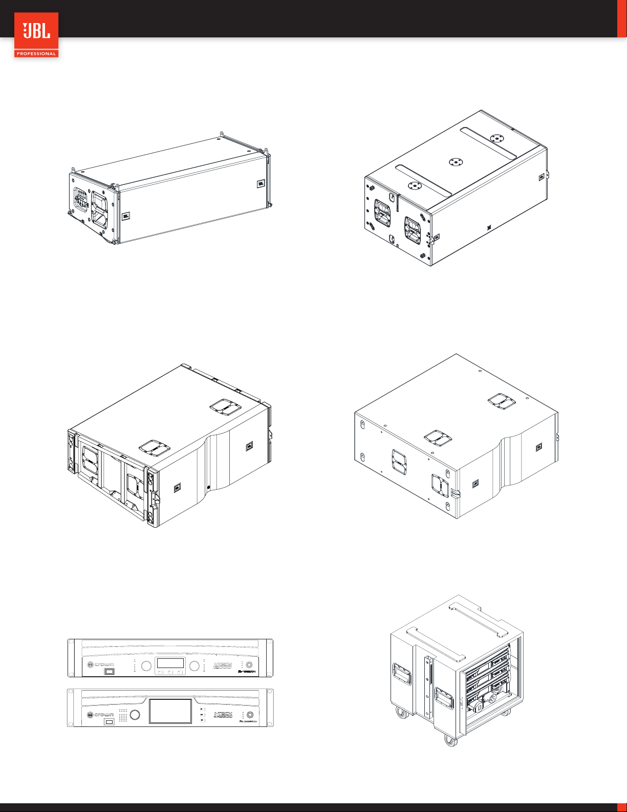
3 - SYSTEM COMPONENTS
VTX A12 | User Manual
VTX A12 / VTX A12W
VTX B28
VTX G28VTX S28
Fault
1
Thermal
1
Clip
-10
-20
Signal
Menu/Exit Prev Next
Ready
Fault
Thermal
1
234
Clip
-10
-20
Signal
Ready
Fault
2
Thermal
2
Clip
-10
-20
Signal
Ready
Menu/Exit
Prev
Next
DRIVECORE SERIES
Power
Bridge 1/2
Bridge 3/4
Data
Power
Bridge 1/2
Bridge 3/4
Data
Crown I-Tech HD Amplifiers Crown V-Rack
10
Page 11
VTX A12 | User Manual
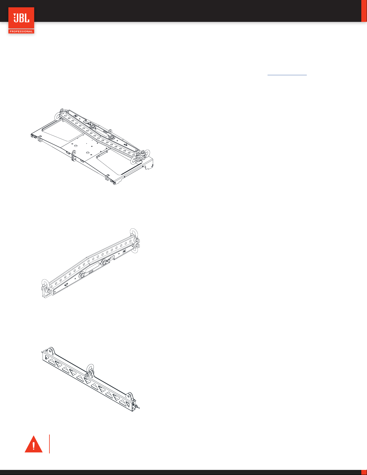
4 - COMPATIBLE ACCESSORIES
All listed accessories are compatible with both the VTX A12 and A12W. For more information on the accessories, refer to the accessory
specification sheets. For more information on usage, refer to the VTX A12 Rigging Manual available at www.jblpro.com.
4.1 VTX A12 AF - ARRAY FRAME
• Array Frame for suspending VTX A12 enclosures
• One Extension Bar included
• Built-in storage position for Extension Bar
• Single, front-to-back and side-by-side suspension points
• High-resolution single-point selection
• Support for up to (24) VTX A12 (array geometry dependent)
• Included laser bracket for LAP-TEQ and RECLINE
4.2 VTX A12 AF EB - ARRAY FRAME EXTENSION BAR
• Extension Bar for use with the VTX A12 AF
• Two Extension Bars can be used for side-by-side suspension
• Support for up to (24) VTX A12 (array geometry dependent)
• Three 5/8-inch shackles included
• Lightweight design
4.3 VTX A12 SB - SUSPENSION BAR
• Compact suspension bar for VTX A12
• Connects to the top or bottom cabinet of an array
• Used to implement pull-back
• Used for suspending VTX A12 enclosures
• Support for up to (18) VTX A12
• Lightweight design
CAUTION: Always use components and accessories specified and approved by JBL Professional. When a cart is used,
use caution when moving the cart to avoid injury from tip-over.
11
Page 12

4.4 VTX A12 VT - VERTICAL TRANSPORTER
• Vertical Transport cart for four VTX A12 enclosures
• Truck pack-friendly dimensions
• Hard top included for easy stacking and transportation
• Built-in stacking features for easy storage
• Ground stacking support with optional accessory
• Heavy-duty casters
• Constructed from steel and aluminum parts
4.5 VTX A12 VT CVR - SOFT COVER
• Heavy-duty cover for four VTX A12 enclosures
VTX A12 | User Manual
• Includes input panel access flaps for easy testing
• Clear see-through pocket for shipping labels
• Handle cutouts for easy transportation
• Padded front section for grill protection
4.6 - VTX A12 VT GND - GROUND STACK ACCESSORY
• Outrigger system for ground stacking VTX A12
• Support for up to six VTX A12 enclosures
• Four screw jacks are included for adjusting height
• Zero-gravity angle set hinge system
• Range: -15 to +5 degrees
• Connects to the VTX A12 VT
4.7 VTX DELTA - DELTA PLATE
• Universal delta plate accessory for VTX systems
• Support for up to (24) VTX enclosures
• Allows for +/- 10-degree horizontal adjustments
• Includes three 5/8-inch shackles
• Working Load Limit: 2,177 kg (4,800 lbs)
12
Page 13

4.8 VTX A12 BP - BASE PLATE
VTX A12 | User Manual
• Enables ground stacking VTX A12 arrays
• Universal M20 threaded pole mount
• Attaches directly to VTX B28 subwoofer enclosure
• Array angles selectable between -15 degrees and +5 degrees
• Two-part lightweight design
• Support for up to six VTX A12 enclosures
• Connects directly to the VTX B28
13
Page 14

5 - SOFTWARE
VTX A12 | User Manual
5.1 LINE ARRAY CALCULATOR 3TM
LAC-3 is simulation software for designing and predicting VTX Se-
ries systems. LAC-3 predicts the acoustical performance of line
array systems, as well as flown and ground-stacked subwoofer ar-
rays. Subwoofer delay values can be generated for electronic delay
steering (EDS) using the built-in coverage calculator. LAC-3 also
performs mechanical validation of rigging hardware, calculates
weight limits, and generates safety warnings.
www.jblpro.com/lac3
5.2 ARRAY LINKTM
Array Link is a mobile companion app that works in conjunction
with LAC-3 software to assist in deployment of VTX Series sys-
tems. Array Link uses a QR code system to transfer all mechani-
cal array information from the main LAC-3 application to a mobile
phone. All relevant rigging and mechanical options are presented in
an easy-to-understand layout. The application is compatible with
iOS® and AndroidTM and can be obtained from their respective
app stores.
5.3 PERFORMANCE MANAGERTM
Performance Manager is a configuration and control application for
networked audio systems. Performance Manager’s user interface
guides system designers through the complete system design,
configuration, and control processes. A dedicated show mode
provides all monitoring and control functions needed to deliver a
complete picture of the system’s performance in real time.
www.jblpro.com/performancemanager
14
Page 15

6 - INTRODUCTION
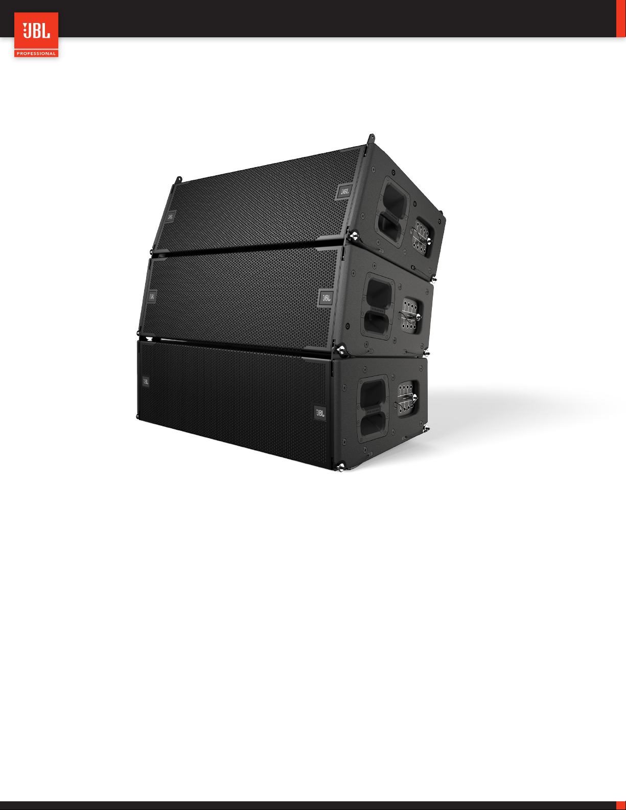
6.1 VTX A12/VTX A12W
VTX A12 | User Manual
JBL VTX A12 is a complete tour sound solution for mid- to large-sized touring applications and high-end fixed installations. VTX A12
was designed from scratch to address the unique challenges of rental companies, FOH engineers, and tour sound production crews.
Next-generation JBL transducer technology and waveguide design deliver unmatched performance, efficiency, and coverage. A pat-
ented JBL rigging mechanism and redesigned suspension system streamline deployment and setup. The VTX A12W is acoustically and
mechanically compatible with the A12 and offers a wider (120-degree) horizontal coverage pattern. VTX A12W can be used standalone
for applications that require wide horizontal coverage or in conjunction with A12 for combination arrays. Refinements to the mechanical
design maximize reliability and versatility, while minimizing size and dramatically reducing weight. VTX A12 isn’t just a superior line ar-
ray—it’s a completely new way to approach tour sound.
KEY MESSAGES
PERFORMANCE
JBL Professional is the world’s leading manufacturer of loudspeaker
systems, using custom-designed and built drivers for optimal per-
formance.
VTX A12’s high frequency (HF) section features three uniquely de-
signed drivers that combine the HF phasing plug and waveguide into
one part providing better tolerances and increased sensitivity above
10 kHz, while reducing distortion and overall weight.
The patented Radiation Boundary Integrator incorporates four 5.5-
inch mid frequency drivers into the high frequency waveguide while
providing a smooth surface for the high frequency horn.
A lightweight 12-inch low frequency woofer (LF) features a fourth-gen-
eration Differential Drive design that adds dual magnets to its dual
voice coil/dual gap construction, and a host of proprietary JBL tech-
nologies for increased excursion, power handling, and sensitivity.
INNOVATIVE RIGGING
VTX A12 marks a giant leap forward in how loudspeakers are
rigged and transported. Four array elements are stacked on
the vertical transporter cart for fast deployment. The rigging
features an auto-locking mechanism, which allows the selec-
tion of angles while components are on the ground; once the
system is suspended, the mechanism automatically locks cab-
inet angles in the designated positions. Set angles simply by
pulling and placing a pin—it’s that easy.
ACCESSORIES
Multiple accessory options provide flexibility in the VTX A12’s
mounting, integration and installation capabilities. Highlights
include a Base Plate that mounts the A12 on top of ground-
stacked subwoofers such as the B28. The array frame and
vertical transporter cart were purpose-built to meet both U.S.
and international truck pack dimensions for the most efficient
system transportation.
15
Page 16

VTX A12 | User Manual
A12
A12 W
A12
A12 W
A12
A12 W
6.2 VTX A12 VS VTX A12W
The A12 is available in standard and wide-coverage versions. The A12 offers 90-degree horizontal coverage, while the A12W offers
120-degree horizontal coverage. The A12 and A12W are acoustically and mechanically compatible, and can be used to create homog-
enous or combination arrays. The A12W’s wider horizontal coverage pattern can be especially useful in providing additional coverage in
short-throw and medium-throw applications.
Mixed arrays of A12 and A12W cabinets can be built to satisfy specific coverage needs. As the listening distance from an array decreas-
es, so does its coverage width. Depending on the venue geometry, A12W speakers can be used at the bottom of an array for broad near-
field coverage. The use of identical components in the A12 and A12W ensures that the transition between the two models is seamless,
without noticeable discrepancies in voicing or headroom.
Since the A12 and A12W require different processing presets to function correctly, they should never be assigned to the same circuit
group. Plan array circuiting accordingly.
6.3 IDENTIFYING A12 AND A12W
From the front, the A12 and A12W look identical, resulting in a clean and consistent look, even when creating mixed arrays. The A12W
input panel is colored blue to differentiate the two models, even when the system is suspended and/or at a distance.
16
Page 17

VTX A12 | User Manual
7 - CONNECTIONS
The VTX A12 is equipped with two Neutrik NL8 speakON connectors, which are wired in parallel, so that one can be used to receive
input while the other acts as a through connection for daisy-chaining cabinets. The NL8 connectors are installed upside down, so that
the NL8 locking pin position can be seen from under the array.
VTX A12 internal NL8 pinout
NL8 Pin Pin 1 +/- Pin 2 +/- Pin 3 +/- Pin 4 +/-
Transducers LF Left LF Right MF HF
7.1 INTERNAL WIRING
LF
1+
1-
2+
2-
3+
3-
4+
4-
1+
1-
2+
2-
3+
3-
4+
4-
MF
HF
CAUTION: Always use high-quality insulated speaker cables from reputable manufacturers. Use cables with a
wire gauge sufficient for the application and keep cable length as short as possible.
17
Page 18

VTX A12 | User Manual
8 - SYSTEM AMPLIFICATION
Like all VTX systems, the VTX A12 is powered exclusively by Crown I-Tech HD amplifiers for optimum performance and consistency
around the world. Crown I-Tech HD Series amplifiers feature BSS Audio OMNIDRIVEHD™ processing on each amplifier channel, includ-
ing the acclaimed LevelMAX™ Limiter Suite and support for linear-phase FIR filters. All A12 processing is performed by the I-Tech HD’s
internal DSP; no other DSP is required. Crown amplifiers include a user-adjustable input section for room correction equalization, array
size compensation, and circuit adjustments.
Standard A12 presets are available for both the Crown I-Tech 4x3500HD and Crown I-Tech 12000HD. The most up-to-date presets
are available for download from www.jblpro.com, and are always bundled in the latest version of JBL’s Performance Manager control
software.
CAUTION: The A12 and A12W require different presets, as each set of presets is designed for a specific speaker
type. A12 and A12W presets are not interchangeable, so the two models cannot be used within the same circuit
group. Independent amplifier drive is required.
8.1 USING THE A12 WITH CROWN I-TECH 4X3500HD
A Crown I-Tech 4x3500HD amplifier can power up to three A12 loudspeakers. Based on the power demands of the A12, this allows for
optimum power-to-transducer ratio without compromising the maximum SPL capabilities of the system. When finer control of coverage
in a venue is needed, smaller coverage areas can be created by using circuits of two cabinets.
Crown I-Tech 4x3500HD JBL VTX A12
Amplifier Channels
Channel 1 A12 LF
Channel 2 A12 LF
Channel 3 A12 MF
Channel 4 A12 HF
18
Page 19

VTX A12 | User Manual
8.2 USING THE A12 WITH CROWN I-TECH 12000HD
A pair of Crown I-Tech 12000HD amplifiers can power up to three VTX A12 loudspeakers. One Crown I-Tech 12000HD powers the low
frequency section, while the other drives the mid and high frequency sections. Based on the power demands of the A12, this allows for
optimum power-to-transducer ratio without compromising the maximum SPL capabilities of the system. When finer control of coverage
in a venue is needed, smaller coverage areas can be created by using circuits of two cabinets.
Crown I-Tech 12000HD JBL VTX A12
Amplifier 1 - Channels
Channel 1 A12 MF
Channel 2 A12 HF
Amplifier 2 - Channels
Channel 1 A12 LF
Channel 2 A12 LF
TIP: Other channel assignments can be implemented when using two-channel Crown I-Tech HD amplifiers. Use JBL’s Per-
formance Manager control software to assign speaker presets.
CAUTION: Make sure the total number of VTX A12 enclosures per circuit/amplifier does not exceed the recom-
mended maximum.
8.3 CROWN AUDIO V-RACK
VTX A12 systems are compatible with the Crown V-Rack 12000HD and Crown V-Rack 4x3500HD touring racks. The number of sup-
ported cabinets per amplifier and wiring options remain the same as the Crown I-Tech examples illustrated in this document. For more
information on the Crown V-Rack products, refer to the V-Rack User Manuals and documentation.
19
Page 20

VTX A12 | User Manual
9 - VTX A12 PRESET LIBRARY
The VTX A12 preset library includes standard array and fill (FL) operating modes, along with full-range and 80 Hz low frequency proc-
cessing for combinations of the A12 with VTX subwoofers. Presets for cardioid array configurations are included for all VTX subwoofer
models. VTX presets are exclusively developed for Crown I-Tech HD amplifiers and come bundled with Performance Manager control
software. Audio Architect™ presets are also available and can be downloaded from www.jblpro.com. Please see below for a detailed
description of VTX A12 operating modes and subwoofer processing options, and refer to the Preset Library setup sheets for preset
descriptions, memory locations, and output channel assignments.
9.1 VTX A12 PRESET MODES AND OPTIONS
Two preset modes and two low frequency processing options are available:
VTX A12 FL: The FL presets (short for FILL) have a nominally flat frequency response and are designed for situations where one or two
A12 cabinets are appropriate, such as for distributed front fills. With this preset, the acoustical low frequency response of the system
extends down to 45 Hz (full-range).
VTX A12 FL 80: The FL 80 presets have nominally flat frequency response and are to be used in situations where one or two A12 cabi-
nets are appropriate, such as for distributed front fills. With this preset, the acoustical low frequency response of the system is set to 80
Hz and used when subwoofers are available.
VTX A12: This is the standard VTX A12 preset for array use. A high frequency shelving response is applied to offset LF/MF array buildup
for nominally focused arrays (equally spaced impact points over the desired audience coverage area). With this preset, the acoustical
low frequency response of the system extends down to 45 Hz (full-range).
VTX A12 80: This is the standard VTX A12 preset for array use with subwoofers. A high frequency shelving response is applied to offset
LF/MF array buildup for nominally focused arrays (equally spaced impact points over the desired audience coverage area). With this
preset, the acoustical low frequency response of the system is set to 80 Hz. The VTX A12 80 preset will generate the highest A-weighted
maximum sound pressure level.
CAUTION: All preset options are available for both the VTX A12 (90-degree coverage pattern) and the VTX A12W
(120-degree coverage pattern). A12 and A12W presets cannot be used interchangeably. Always use the appropri-
ate preset to guarantee proper system performance.
TIP:
• Both the full-range and 80 Hz presets can be used with subwoofers, depending on the application and subwoofer
arrangement. For more information on subwoofer use, see chapter 10 – Subwoofer Options.
• Mixing FL and standard presets in the same array is not recommended.
• The VTX A12 presets provide a well-balanced tonal starting point for a given array size. The Array Size Compensation
filter in the JBL Line Array Control Panel (LACP) can be used to further fine-tune tonal balance for a given array size
and shape. Please refer to chapter 12 - Line Array Control Panel for more information.
20
Page 21

VTX A12 | User Manual
Frequency (Hz)
SPL (dB)
20
10 - SUBWOOFER OPTIONS
VTX A12 presets are designed for a 3:2 minimum ratio of A12 cabinets to VTX B28 or S28/G28 subwoofers. The 3:2 ratio provides suffi-
cient headroom for both the subwoofers and the A12s to reach their MAX SPL (i.e. limiter threshold) at the same time, while maintaining
a minimum of 10 dB subwoofer to full-range low frequency contour. Other ratios can be used depending on the desired tonal balance
target, MAX SPL, and application.
VT X A12 VT X B28
10.1 SUB/LF PRESET OPTIONS
As mentioned, there are two LF presets available for the A12 system: the VTX A12 (full-range) preset, which extends the frequency re-
sponse of the system down to 45 Hz, and the VTX A12 80 (80 Hz) preset, which extends the frequency response of the system down
to 80 Hz. The VTX A12 (full-range) preset is used when the system is operated without subwoofers or when the application calls for
extended LF response from the main arrays. The VTX A12 80 (80 Hz) preset is used only when subwoofers are available and the highest
A-weighted sound pressure level (SPL) is required. When multiple A12 arrays are used (e.g. main and side arrays), all A12 arrays should
be operated in the same LF mode for headroom consistency and proper summation. Subwoofers are typically set to the mode corre-
sponding to the mode selected for the A12.
Example 1: A12 80 | SUB: 80 Example 2: A12 FR | SUB: 60/80
20
10
10
SUB: 80Hz
0
SPL (dB)
-10
-20
20 100 1000
Frequency (Hz)
21
0
-10
-20
20 100 1000
SUB: 60Hz
Page 22

10.2 PRESET EXAMPLE 1
VTX A12 | User Manual
A12 Full-range or 80 Hz
VTX B28 60 Hz or 80 Hz
10.3 PRESET EXAMPLE 2
A12 Full-range or 80 Hz
VTX B28 60 Hz or 80 Hz
VTX B28 80 VTX B28 80
VTX A12 80 VTX A12 80
VTX A8 FL 80
VTX B28 80
22
Page 23

VTX A12 | User Manual
10.4 TIME ALIGNMENT
The VTX A12 presets provide proper system summation with companion VTX subwoofers in physically coupled configurations (stacked
or suspended), and when used with corresponding subwoofer presets. This pre-alignment is done at the factory, allowing any VTX sub-
woofer to be used with any VTX loudspeaker without the need for subwoofer presets specific to each system and configuration. When
the VTX A12 is operated in full-range mode with companion subwoofers, some additional delay should be applied to the subwoofers to
match the A12.
VTX A12 VTX B28
Additional time alignment delay should be added as needed to account for physical path length differences between suspended A12
arrays and ground-stacked subwoofers. If no acoustic measurement system is available, delay values can be calculated based on the
geometric path difference between a reference point (i.e. FOH position) and each system. This method is effective because every VTX
preset includes a factory pre-delay to correctly align all components. When the latency of a system is unknown, this method is not ef-
fective and should not be used. This can occur when the signal paths of different parts of the system vary in latency.
Path Difference = dFlown Array - dSub
Sub Delay =
Path Diff
Sub Delay =
Path Difference (meters)
343 (meters / second)
or
Path Difference (feet)
1140 (feet / second)
23
dFlown Array
dSub
dSub
Page 24

VTX A12 | User Manual
11 - FREQUENCY RESPONSE
The frequency response of a line array is determined by many factors, including the array size (number of boxes), array curvature (cab-
inet-to-cabinet angles) and listening distance. JBL factory presets are designed to create a well-balanced tonal starting point for given
array conditions. For example, the standard array presets are designed to work optimally with array sizes between eight and 12 cabinets
and equal impact spacing for a flat listening plane. An array with these parameters generates a flat HF frequency response with a grad-
ual rise in LF energy. The frequency at which the response starts rising depends on the array parameters mentioned above. A relatively
short array starts rising at a lower frequency than a longer array. Below are examples of the frequency responses of A12 arrays using the
standard VTX A12 presets with no additional equalization/correction (flat).
Example 1 : A12 Frequency response vs number of cabinets
20
Frequency response of a 12-cabinet A12 array
10
0
SPL (dB)
-10
-20
20 100 1000 10000 20000
Frequency (Hz)
Example 2: Standard preset vs 80 preset
20
10
0
SPL (dB)
-10
-20
20 100 1000 10000 20000
Frequency (Hz)
Frequency response of an eight-cabinet A12 array
Frequency response of a six-cabinet A12 array
Frequency response of a four-cabinet A12 array
Frequency response of a 12-cabinet A12 array
Frequency response of a 12-cabinet A12 array using the
80 Hz preset
Since a factory preset cannot account for all variables and array configurations, user adjustment of certain DSP parameters is neces-
sary to achieve the desired tonal balance for a given array and application. The LF response of any VTX line array system can be easily
adjusted using the Array Size Compensation Filter in the Line Array Control Panel. The Array Size Compensation Filter was specifically
designed to compensate for LF/MF buildup with a single, adjustable parameter. Lowering the gain value of this filter shifts down the
frequency at which LF response starts rising — similar to shortening the length of an array.
24
Page 25

12 - LINE ARRAY CONTROL PANEL
VTX A12 | User Manual
The JBL Line Array Control Panel (LACP) was designed to tailor
the tonal balance of a line array with its five adjustable DSP filters.
Each filter serves a specific purpose and accelerates the system
tuning process. Two filters are global, grouped across the entire
array, while the other three filters are designated for circuit-spe-
cific adjustments.
12.1 ACCESSING LACP
LACP filters can be modeled in Line Array Calculator 3 software and then imported into Performance Manager for deployment to actual
devices. To access LACP within Line Array Calculator 3 use the grouping feature to create circuit groups. The groups should represent
the actual array amplification. This enables realistic and accurate DSP adjustments. After creating the circuit groups, click the LACP
button under the DSP column. Global filters, like Filters 1 and 2, are automatically applied to all circuit groups in the array.
25
Page 26

VTX A12 | User Manual
12.2 FILTER 1 - ARRAY SIZE COMPENSATION
Filter 1 is used to correct for LF/MF buildup when the array size or shape differ from that for which the factory preset was designed.
Filter 1 is automatically applied globally to provide uniform LF adjustments to all cabinets in the array. Filter 1 is a continuously variable
low-shelving filter. Its parameters (corner frequency and slope) are adjusted based on the applied gain value. Array buildup is different
for each configuration, and Filter 1 is optimized to correct for this effect using only one parameter (Gain).
12.3 FILTER 2 - ATMOSPHERIC ABSORPTION COMPENSATION
Filter 2 compensates for atmospheric conditions such as large variations in temperature and humidity, which can impact overall HF
energy. Filter 2 is applied globally and can be used to quickly brighten or darken an array. This filter can also be used to adjust overall
system tonal balance to taste.
12.4 FILTER 3 - HF THROW DISTANCE COMPENSATION
Filter 3 is used to correct for distance offsets between different sections of an array. The Type, Frequency, and Q parameters are linked
across the entire array, but the Gain parameter is adjustable per circuit group. This filter can be used to reduce HF energy delivered close
to an array and increase HF energy reaching further areas, where air absorption has a bigger impact.
12.5 FILTERS 4 & 5 - USER PEQ 1 & 2
Filters 4 and 5 are User parametric EQs, which can be applied to individual circuit groups. As the Frequency and Q parameters are not
linked across circuits, it is recommended that User PEQ 1 & 2 be used only for moderate gain changes of frequencies above 1kHz.
26
Page 27

VTX A12 | User Manual
12.6 EXAMPLE USING LACP
This example is for a 12-cabinet VTX A12 array. The standard A12 preset is used, with the Array Size Compensation filter set to –3 dB
to offset LF buildup and achieve a flatter frequency response. As seen from the illustration below, Array Size Compensation is globally
applied to all array circuits. The HF Throw Distance compensation filter (Filter 3) on the bottom circuit can apply HF attenuation to correct
for proximity differences. Simple adjustments to the LACP filters can get an A12 system to a very good staring point. Further required
adjustments will depend on the room and specific application.
TIP: The LACP parameters used in LAC-3 to predict an array can be easily applied to an actual array in Performance
Manager. For information on how to import LACP parameters into Performance Manager, please refer to the Performance
Manager documentation.
27
Page 28

VTX A12 | User Manual
13 - TESTING VTX A12
Speakers need to be periodically checked and maintained to assure long-term performance and reliability. While the VTX A12 is designed
for the utmost reliability, it is important to confirm that the system is operating within specified tolerances to ensure optimal performance
for years to come. Below are two methods that can be used to check and verify proper transducer performance in a VTX A12 system.
13.1 USING A DMM (DIGITAL MULTIMETER)
This method is best suited for when the speaker system is in the shop. A DCR (DC resistance) test with a multimeter can give a very
accurate reading of how many transducers are properly wired together and within their standard operating tolerances. This test is ap-
propriate for individual cabinets and not groups.
With the A12 speaker unconnected to any amplifiers, set a DMM to the resistance (Ω) setting and place the probes across the 1+/-, 2+/-,
3+/-, and 4+/- leads. Record the values indicated on the DMM for each pair of leads and refer to the chart below to either confirm correct
readings or investigate out-of-tolerance DCR readings.
HF Section (Pin 4)
DCR Tolerance
All drivers functioning 7.0 Ω +/- 0.2 Ω
1 x HF Driver open 10.3 Ω +/- 0.2 Ω
2 x HF Drivers open 20.5 Ω +/- 0.2 Ω
3 x HF Drivers open OL -
Any driver shorted 0.2 Ω -
MF Section (Pin 3)
DCR Tolerance
All woofers functioning 5.4 Ω +/- 0.2 Ω
1 x woofer open 10.8 Ω +/- 0.2 Ω
LF Section (Pin 1 / 2)
DCR Tolerance
Functioning woofer 5.5 Ω +/- 0.2 Ω
Shorted 0.2 Ω -
Notes:
• The DCR values listed above assume room temperature transducers. If measurements are taken right after use, when the transduc-
ers are warm, the values will vary. For best results, test the speakers cold.
• The DCR value of a transducer gives an accurate representation of its electrical state, but mechanical defects are not characterized
by this test. Refer to the VTX A12 Service Manual for instructions on performing a rub-and-buzz test with a sine wave generator.
28
Page 29

VTX A12 | User Manual
13.2 USING PERFORMANCE MANAGER
When in the field, the Test System Mode in Performance Manager can be used to test an A12 system. This test method is quick and
especially useful for determining whether all the speaker cables, including cabinet-to-cabinet NL8 jumpers, are properly functioning.
To perform the test, Performance Manager uses the I-Tech HD’s built-in noise generator, in conjunction with the amplifier’s current draw
and voltage-sensing capabilities, to generate a nominal load impedance reading for each amplifier output channel. Since broadband
pink noise is used as the test stimulus, the returned value is considered to be an impedance value, and it will differ from the resistance
values given earlier in this document (which are taken using DC voltage as the stimulus). `
STEPS:
1
• Make sure Performance Manager is online and connected to the devices.
2
• Navigate to the Test System Mode and make sure all speakers are muted.
3
• Switch the Noise Generator to the ON position and set the level to a value between -30 dB and -10 dB. Values lower than -30
dB may not be sufficient to trigger a reading.
4
• Unmute the speaker or a bandpass to start the measurement. The measured value is displayed on the speakers.
13.3 PERFORMANCE MANAGER READINGS
Below are the expected impedance values for a single VTX A12, a circuit of two A12 cabinets, and a circuit of three A12s. The measure-
ments below were taken at room temperature with a cable length of 25 m (82 ft). Acceptable tolerance is +/- 0.5 Ω.
1 x VTX A12 2 x VTX A12 3 x VTX A12
Variances in temperature, cable length, wire gauge, and usage can make the measurements recorded by Performance Manager more
susceptible to drift. However, variations in conditions like temperature are common across all similar circuits of a system. More important
than the individual component values is consistency across similar circuits. For example, all three-cabinet circuits for an array should
measure similarly. If one is off by several ohms, there is likely something wrong with that specific circuit.
29
Page 30

14 - SPECIFICATIONS
SYSTEM
14.2 VTX A12 SPECIFICATIONS
Frequency Range (-10 dB):
46 Hz - 19 kHz (Preset: VTX A12)
VTX A12 | User Manual
Coverage Pattern (-6 dB)
Horizontal:
Vertical:
System Input Power Rating
MF:
HF:
Maximum Peak Output²:
System Amplification:
Required Amplifier Channels:
Number of Cabinets per Circuit:
System Impedance:
TRANSDUCERS
Low Frequency :
Mid Frequency :
High Frequency :
90 degrees nominal (250 Hz - 18 kHz)
Varies with array size and configuration
1
2x 800W Continuous (IEC/100 hour)
LF:
400W Continuous (IEC/100 hour)
150W Continuous (IEC/100 hour)
146 dB (Preset: VTX A12)
Crown I-Tech 9000HD
Crown I-Tech 12000HD
Crown I-Tech 4x3500HD
(4) channels (LF|LF|MF|HF)
(3) VTX A12
LF: 2x 8 ohms | MF: 8 ohms | HF: 8 ohms
(2) JBL 2264H, 12 in diameter, dual 3 in diameter voice coil, Neodymium Differential Drive®
(4) JBL 2165H, 5.5 in diameter, dual 2 in diameter voice coil, Neodymium Differential Drive®
(3) JBL 2423K, 2 in diameter annular diaphragm, 2 in diameter voice coil, Neodymium compression drivers
ENCLOSURE
Construction :
IP Rating3 :
Suspension :
15 mm 11-ply Finnish birch plywood, Black DuraFlexTM finish, four integral recessed handles
IP55 EN (60529)
High-grade steel with anti-corrosion coating, captive suspension plates, quick release pins, auto-locking mechanism for setting angles
Inter-enclosure Angle (deg) :
0.25, 0.5, 1, 1.5, 2, 2.5, 3, 4, 6, 8, 10
Powder coated 1.8 mm (14-guage), hex-perforated steel with acoustically transparent black cloth backing
Grill :
Connectors
(2) Neutrik® speakON® NL-8
Type :
Pin Assignments :
Pins 1 ± (LF), Pins 2 ± (LF),
Pins 3 ± (MF), Pins 4 ± (HF)
Dimensions (H x W x D) :
330 mm x 1118 mm x 495 mm
13 in x 44 in x 19.5 in
Net Weight :
Footnotes:
1: IEC Standard: IEC shaped noise with 6 dB crest factor based on nominal impedance and a duration of 100 hours
2: Peak, unweighted SPL, measured under full-space conditions at 1 meter using broadband pink noise with a 12dB crest factor and specified preset
3: Front face at 0 degree or greater down angle to allow the cabinet to drain water. Suspension components fully weather rated for indoor or covered outdoor conditions where humidity is nominally under 50% and not local
to bodies of corrosive materials. Unused speakON connectors must be sealed using silicone to protect against water and moisture
JBL continually engages in research related to product improvement. Some materials, production methods and design refinements are introduced into existing products without notice as a routine expression of that
philosophy. For this reason, any current JBL product may differ in some respect from its published description, but will always equal or exceed the original design specifications unless otherwise stated.
60.8 kg (134 lbs)
30
Page 31

14.2 VTX A12W SPECIFICATIONS
SYSTEM
Frequency Range (-10 dB):
46 Hz - 19 kHz (Preset: VTX A12W)
VTX A12 | User Manual
Coverage Pattern (-6 dB)
Horizontal:
Vertical:
System Input Power Rating
MF:
HF:
Maximum Peak Output²:
System Amplification:
Required Amplifier Channels:
Number of Cabinets per Circuit:
System Impedance:
TRANSDUCERS
Low Frequency :
Mid Frequency :
High Frequency :
120 degrees nominal (250 Hz - 18 kHz)
Varies with array size and configuration
1
2x 800W Continuous (IEC/100 hour)
LF:
400W Continuous (IEC/100 hour)
150W Continuous (IEC/100 hour)
146 dB (Preset: VTX A12W)
Crown I-Tech 9000HD
Crown I-Tech 12000HD
Crown I-Tech 4x3500HD
(4) channels (LF|LF|MF|HF)
(3) VTX A12W
LF: 2x 8 ohms | MF: 8 ohms | HF: 8 ohms
(2) JBL 2264H, 12 in diameter, dual 3 in diameter voice coil, Neodymium Differential Drive®
(4) JBL 2165H, 5.5 in diameter, dual 2 in diameter voice coil, Neodymium Differential Drive®
(3) JBL 2423K, 2 in diameter annular diaphragm, 2 in diameter voice coil, Neodymium compression drivers
ENCLOSURE
Construction :
IP Rating3 :
Suspension :
15 mm 11-ply Finnish birch plywood, Black DuraFlexTM finish, four integral recessed handles
IP55 EN (60529)
High-grade steel with anti-corrosion coating, captive suspension plates, quick release pins, auto-locking mechanism for setting angles
Inter-enclosure Angle (deg) :
0.25, 0.5, 1, 1.5, 2, 2.5, 3, 4, 6, 8, 10
Powder coated 1.8 mm (14-guage), hex-perforated steel with acoustically transparent black cloth backing
Grill :
Connectors
(2) Neutrik® speakON® NL-8
Type :
Pin Assignments :
Pins 1 ± (LF), Pins 2 ± (LF),
Pins 3 ± (MF), Pins 4 ± (HF)
Dimensions (H x W x D) :
330 mm x 1118 mm x 495 mm
13 in x 44 in x 19.5 in
Net Weight :
Footnotes:
1: IEC Standard: IEC shaped noise with 6 dB crest factor based on nominal impedance and a duration of 100 hours
2: Peak, unweighted SPL, measured under full-space conditions at 1 meter using broadband pink noise with a 12 dB crest factor and specified preset
3: Front face at 0 degree or greater down angle to allow the cabinet to drain water. Suspension components fully weather rated for indoor or covered outdoor conditions where humidity is nominally under 50% and not local
to bodies of corrosive materials. Unused speakON connectors must be sealed using silicone to protect against water and moisture
JBL continually engages in research related to product improvement. Some materials, production methods and design refinements are introduced into existing products without notice as a routine expression of that
philosophy. For this reason, any current JBL product may differ in some respect from its published description, but will always equal or exceed the original design specifications unless otherwise stated.
60.8 kg (134 lbs)
31
Page 32

15 - ACOUSTIC MEASUREMENTS
Frequency (Hz)
20 180
-180
SPL (dB)
20000
Frequency (Hz)
360
-6 dB Beamwidth (degrees)
Frequency (Hz)
20 180
-180
SPL (dB)
20000
Frequency (Hz)
360
-6 dB Beamwidth (degrees)
15.1 VTX A12
VTX A12 | User Manual
FREQUENCY RESPONSE
10
0
-10
-20
20 100 1000 10000 20000
VTX A12 FL VTX A12 FL 80 VTX A12 Phase
15.2 VTX A12W
FREQUENCY RESPONSE
10
0
BEAMWIDTH
90
0
-90
100
10
20 100 1000
Horizontal Beamwidth
BEAMWIDTH
90
0
100
-10
-20
20 100 1000 10000 20000
VTX A12W FL VTX A12W FL 80 VTX A12W Phase
-90
10
20 100 1000
Horizontal Beamwidth
32
Page 33

16 - DIMENSIONS
VTX A12 | User Manual
1091 mm (43 in)
330 mm (13 in)
1117 mm (44 in)
165 mm (6.5 in)
203 mm (7.9 in)
10.00°
493 mm (19.4 in)
33
Page 34

17 - CONTACTS INFORMATION
UNITED STATES OF AMERICA
VTX A12 | User Manual
HARMAN Professional Solutions
8500 Balboa Blvd.
Northridge, CA 91329
USA
+1 (844) 776-4899
www.jblpro.com
PROFESSIONAL CONTACTS OUTSIDE THE U.S.A.:
Contact the JBL Professional distributor in your area. A complete list of JBL Professional international distributors is provided at our
U.S.A. website: www.jblpro.com
HARMAN Professional EMEA
Westside
London Road
Hemel Hempstead
HP3 9TD
United Kingdom
www.pro.harman.com
www.jblpro.com/support
U.S.A. Technical Support
+1 (800) 852-5776
HProTechSupportUSA@Harman.com
www.jblpro.com
HARMAN Professional APAC
108 Pasir Panjang Road
#02-08 Golden Agri Plaza
Singapore 118535
+65 6870-5000
www.pro.harman.com
www.jblpro.com/support
HARMAN Professional China
20F, China Merchants Port Plaza, #1
Gongye 3rd Road, Shekou, Nanshan
Dist.
Shenzhen, 518067, China
400 166 7806
www.harman.com/China
HARMAN Professional India
Prestige Technology Park
Jupiter 2A Block, 4th Floor
Marathahalli Ring Road
Bangalore 560103, India
+1 (800) 208-8880
www.harman.com/India
India In-Country Support
www.harman.com/india/india-service-center
China In-Country Support
ChinaPRO.Service@harman.com
HARMAN Professional Brazil
Br386, Km435 92480-000
Nova Santa Rita Rs
Brazil
+55 51 34794000
www.harman.com/Brasil
www.jblaudio.com.br
Brazil In-Country Support
tecnica@harman.com
34
Page 35

 Loading...