


VMA Series
VMA160
VMA1120
VMA1240
VMA260
VMA2120
Commercial Series
1 Channel & 2 Channel Mixer-Amplifier
Operation Manual
1 2 3 4 MUSIC
VMA 160
VMA 260
1
1 2 3 MUSIC 1 4 5 6 MUSIC 2
1
4
MASTER
USB
MASTER 2MASTER 1
USB

Contents
Important Safety Information ..............................................................................................................................3
EC - Declaration of Conformity ...........................................................................................................................5
1.0 Welcome .......................................................................................................................................................6
1.1 Features ....................................................................................................................................................6
1.2 Front Panel Controls & Indicators .............................................................................................................7
1.3 Rear Panel Controls & Connectors (VMA160, VMA1120, VMA1240) ......................................................8
1.4 Rear Panel Controls & Connectors (VMA260 & VMA2120)
2.0 Setup ..........................................................................................................................................................10
2.1 Unpacking Your Amplier ......................................................................................................................10
2.2 Installing Your Amplier ..........................................................................................................................10
2.3 Ensuring Proper Cooling ........................................................................................................................13
2.4 Choosing Input Wire & Connectors ........................................................................................................13
2.5 Output Wiring & Connectors ..................................................................................................................14
2.6 Wiring Your Audio System ......................................................................................................................15
2.7 Connecting to AC Mains .......................................................................................................................16
2.8 Protecting Your Speakers ......................................................................................................................16
2.9 Startup Procedure .................................................................................................................................16
3.0 Operation ....................................................................................................................................................17
3.1 Precautions .............................................................................................................................................17
3.2 Input Routing ..........................................................................................................................................18
3.3 Conguration Settings ............................................................................................................................18
3.3.1 70V/100V Output Selection .............................................................................................................18
3.3.2 Chime Function ...............................................................................................................................18
3.3.3 Line/Mic Gain Switch ......................................................................................................................18
3.3.4 Phantom Power ...............................................................................................................................18
3.4 VOX Function ..........................................................................................................................................19
3.5 Priority Muting .........................................................................................................................................19
3.6 Remote Volume Control ..........................................................................................................................19
3.7 Media Player ...........................................................................................................................................20
3.7.1 Bluetooth Operation ........................................................................................................................20
3.7.2 USB Operation ................................................................................................................................20
3.7.3 Additional Media Player Information ...............................................................................................21
3.7.4 Firmware Upgrade Procedure ........................................................................................................21
4.0 Troubleshooting ..........................................................................................................................................22
Appendix A: Target Performance Specications .............................................................................................23
Appendix B: Block Diagrams ...........................................................................................................................24
Appendix C: Contact Information .....................................................................................................................27
.............................................................9
This manual does not include all of the details of design, production, or variation of the equipment. Nor does it cover every
possible situation which may arise during installation, operation or maintenance.
The information provided in this manual was deemed accurate as of the publication date. However, updates to this information
may have occurred.
Trademark Notice: JBL is registered trademark of JBL International. Crown and DriveCore are registered trademarks of Crown
Audio. Other trademarks are the property of their respective owners.
© 2016 JBL Commercial, 10653 S. River Front Parkway, Suite 300 South Jordan, UT 84095, USA. All Rights Reserved.
2

IMPORTANT SAFETY INFORMATION
WARNING
RISK OF ELETRIC SHOCK
DO NOT OPEN
AVERTISSEMENT:
RISQUE DE CHOC ELECTRIQUE - NE PAS OUVRIR
WARNING:
TO THE REDUCE THE RISK OF FIRE OR ELECTRIC
SHOCK DO NOT EXPOSE THIS EQUIPMENT TO RAIN OR MOISTURE
The symb ols shown ab ove are internationally accepted sy mbols
that warn o f potential hazards with electr ical produ cts. The li ghtning flash w ith arrow point in an equilateral tria ngle means th at
there are dangerous vo ltages present within t he unit. The exclamation poin t in an equilateral triangle indicates that it is nece ssary fo r
the user to refer to the owner’s manual.
These sy mbols warn that the re are no user servi ceable parts in side
the unit. D o not open the unit. Do not at tempt to service the u nit
yourself. Refer all servicing to qualified personnel. Opening the
chassis f or any reason will vo id the manufact urer’s warrant y. Do not
get the uni t wet. If liquid is spi lled on the unit, shu t it off immediate ly
and take it to a dealer for s ervice. D isconnec t the unit during
storms to prevent damage.
SAFETY INSTRUCTIONS
NOTI CE FOR C USTOMERS IF YOUR UN IT IS EQ UIPP ED WITH A POWER
CORD.
WARNING: THIS APPLIANCE SHALL BE CONNECTED TO A MAINS SOCKET
OUTLET WITH A PROTECTIVE EARTHING CONNECTION.
The cores in the mains lead are colored in accordance with the following code:
GREEN and YELLOW - Earth BLUE - Neutral BROWN - Live
As colors of the cores in the mains lead of this appliance may not correspond with the colored markings identifying the terminals in your plug,
proceed as follows:
•
The core which is colored green and yellow must be connected to the
terminal in the plug marked with the letter E, or with the earth symbol,
or colored green, or green and yellow.
•
The core which is colored blue must be connected to the terminal
marked N or colored black.
•
The core which is colored brown must be connected to the terminal
marked L or colored red.
This equipment may require the use of a different line cord, attachment
plug, or both, depending on the available power source at installation. If
the attachment plug needs to be changed, refer servicing to qualified service personnel who should refer to the table below. The green/yellow wire
shall be connected directly to the units chassis.
CONDUCTOR
L LIVE BROWN BLACK
N NEUTRAL BLUE WHITE
E EARTH GND GREEN/YEL GREEN
WARNING: If the ground is defeated, certain fault conditions in the unit or in
the system to which it is connected can result in full line voltage between
chassis and earth ground. Severe injury or death can then result if the
chassis and earth ground are touched simultaneously.
WIRE COLOR
Normal Alt
WARNING FOR YOUR PROTECTION
READ THESE INSTRUCTIONS:
KEEP THESE INSTRUCTIONS
HEED ALL WARNINGS
FOLLOW ALL INSTRUCTIONS
THE A PPAR ATUS SH ALL N OT BE EXPOSED TO DRI PPING OR
SPL ASHING LIQUID A ND NO OB JECT FILL ED WITH LIQUID, SU CH
AS VASES, SH ALL BE PLAC ED ON TH E APPARATUS
CLE AN ONLY WITH A DRY CLOTH.
DO NOT BLOCK AN Y OF TH E VENTILATION OP ENIN GS. IN STALL I N
ACCORDANCE WITH THE MANUFACTURER’S INSTRUCTIONS.
DO NOT INSTALL NEA R ANY H EAT SOU RCES S UCH AS
RADIATORS, HEAT R EGISTERS, STOVE S, OR OTHER AP PARATUS
(INCLUDING AMPLIFIERS) THAT PRODUCE HEAT.
ONLY USE ATTACHMENTS/ACCESSORIES SPECIFIED BY THE
MANUFACTURER.
UNPLUG TH IS APPA RATU S DURING LIGHTNING STORMS O R WHEN
UNUSED FOR LONG PERIODS OF TIME.
Do not defeat the safet y purpose of the polarized or grounding-type
plug. A polarized plug has t wo blades with one wider than the
other. A grounding type plug has two blades and a third grounding
prong. The wide blade or third prong are provided for your safety. If
the provided plug does not fit your outlet, consult an electrician for
replacement of the obsolete outlet.
Protect the power cord from being walked on or pinched particularly
at plugs, convenience receptacles, and the point w here they exit from
the apparatus.
Use only with the cart stand, tripod bracket, or table specified by
the manufacture, or sold with the apparatus. When a cart is used,
use caution when moving the cart/apparatus combination to avoid
injury from tip-over. Refer all servicing to qualified service personnel.
Servicing is required when the apparatus has been damaged in any
way, such as power-supply cord or plug is damaged, liquid has been
spilled or objects have fallen into the apparatus, the apparatus has
been exposed to rain or moisture, does not operate normally, or has
been dropped.
POWE R ON/O FF SWI TCH: For products provided with a power
switch, the power switch DOES NOT break the connection from the
mains.
MAI NS DIS CONN ECT: The plug shall remain readily operable. For
rack-mount or installation where plug is not accessible, an all-pole
mains switch with a cont act separation of at leas t 3 mm in each
pole shall be incorporated into the electrical installation of the rack
or building.
FOR UNITS EQUIPPED WI TH EX TER NAL LY ACCES SIBLE FUS E
RECE PTACLE: Replace fuse with same type and rating only.
MULTIPLE- INPU T VOLTAGE: T his equipment may require the use
of a different line cord, attachment plug, or both, depending on the
available power source at installation. Connec t this equipment only to
the power source indicated on the equipment rear panel. To reduce
the risk of fire or electric shock, refer servicing to qualified service
personnel or equivalent.
If connected to 240V supply, a suitable CSA/UL certified power cord shall
be used for this supply.
3
IMPORTANT SAFETY INFORMATION
A molded mains plug that has been cut off from the cord is unsafe.
Discard the mains plug at a suitable disposal facility. NEVER UNDER ANY
CIRCUMSTANCES SHOULD YOU INSERT A DAMAGED OR CUT MAINS PLUG
INTO A 13 AMP POWER SOCKET. Do not use the mains plug without the
fuse cover in place. Replacement fuse covers can be obtained from your
local retailer. Replacement fuses are 13 amps and MUST be ASTA approved
to BS1362.
U.K. MAINS PLUG WARNING
ELECTROMAGNETIC
This device complies with part 15 of the FCC Rules and the Product speci-
COMPATIBILITY
fications noted on the Declaration of Conformity. Operation is subject to the
following two conditions:
•
This device may not cause harmful
interference, and
•
This device must accept any interference received, including interfer-
ence that may cause undesired operation.
Operation of this unit within significant
electromagnetic fields should be avoided.
•
Use only shielded interconnecting cables.
USE GROUNDED OUTLET ONLY!
Apparatet må tilkoples jordet stikkontakt
Apparaten skall anslutas till jordat uttag
Laite on liitettävä suojakoskettimilla varustettuun pistorasiaan
MAGNETIC FIELD
CAUTION! Do not locate sensitive high-gain equipment such as
preamplifiers or tape decks directly above or below the unit. Because this
amplifier has a high power density, it has a strong magnetic field which
can induce hum into unshielded devices that are located nearby. The field
is strongest just above and below the unit.
If an equipment rack is used, we recommend locating the amplifier(s)
in the bottom of the rack and the preamplifier or other sensitive equip
ment at the top.
If you want to dispose this product, do not mix it with
general household waste. There is a separate collection
system for used electronic products in accordance with
legislation that requires proper treatment, recovery
and recycling.
Private household in the 25 member states of the EU, in Switzerland
and Norway may return their used electronic products free of charge
to designated collection facilities or to a retailer (if you purchase a
similar new one).
For Countries not mentioned above, please contact your local authorities for a correct method of disposal.
By doing so you will ensure that your disposed product undergoes
the necessary treatment, recovery and recycling and thus prevent
potential negative effects on the environment and human health.
FEDERAL COMMUNICATION
COMMISSION INTERFERENCE STATEMENT
This equipment has been tested and found to comply with the limits for a Class B digital
device, pursuant to Part 15 of the FCC Rules. These limits are designed to provide
reasonable protection against harmful interference in a residential installation. This
equipment generates, uses and can radiate radio frequency energy and, if not installed
and used in accordance with the instructions, may cause harmful interference to radio
communications. However, there is no guarantee that interference will not occur in a
particular installation. If this equipment does cause harmful interference to radio or
television reception, which can be determined by turning the equipment off and on, the
user is encouraged to try to correct the interference by one of the following measures:
• Reorient or relocate the receiving antenna.
• Increase the separation between the equipment and receiver.
• Connect the equipment into an outlet on a circuit different from that to which
the receiver is connected.
• Consult the dealer or an experienced radio/TV technician for help.
FCC CAUTION
Any changes or modifications not expressly approved by the party responsible for
compliance could void the user’s authority to operate this equipment.
This device complies with Part 15 of the FCC Rules. Operation is subject to the
following two conditions:
1. This device may not cause harmful interference, and
2. This device must accept any interference received, including interference that
may cause undesired operation.
IMPORTANT NOTE
This equipment complies with FCC radiation exposure limits set forth for an
uncontrolled environment. This transmitter module must not be colocated or operated
in conjunction with any other antenna or transmitter. This End equipment should be
installed and operated with a minimum distance of 20 centimeters between the radiator
and your body.
CANADA STATEMENT
This device complies with Industry Canada’s licence-exempt RSSs. Operation is subject
to the following two conditions:
1. This device may not cause interference; and
2. This device must accept any interference, including interference that may cause
undesired operation of the device.
This device complies with Industry Canada’s licence-exempt RSSs. Operation is subject
to the following two conditions:
1. l’appareil ne doit pas produire de brouillage;
2. l’utilisateur de l’appareil doit accepter tout brouillage radioélectrique subi,même
si le brouillage est susceptible d’en compromettre le fonctionnement.
-
CAUTION EXPOSURE
This device meets the exemption from the routine evaluation limits in section 2.5 of
RSS102 and users can obtain Canadian information on RF exposure and compliance.
Le dispositif répond à l’exemption des limites d’évaluation de routine dans la section
2.5 de RSS102 et les utilisateurs peuvent obtenir des renseignements canadiens sur
l’exposition aux RF et le respect.
THE FINAL END PRODUCT MUST BE LABELLED IN
A VISIBLE AREA WITH THE FOLLOWING
The Industry Canada certification label of a module shall be clearly visible at all times
when installed in the host device, otherwise the host device must be labelled to display
the Industry Canada certification number of the module, preceded by the words
“Contains transmitter module”, or the word “Contains”, or similar wording expressing
the same meaning, as follows: “Contains transmitter module IC: 6132A-MB8811VMA”
This End equipment should be installed and operated with a minimum distance of 20
centimeters between the radiator and your body.
Cet équipement devrait être installé et actionné avec une distance minimum de 20
centimètres entre le radiateur et votre corps.
The end user manual shall include all required regulatory information/warning as shown
in this manual.
4

EC - DECLARATION OF CONFORMITY
Brand: JBL
Equipment Type: Commercial Mixer-Amplifiers
Model names: VMA160, VMA1120, VMA1240, VMA260, VMA2120
We, Harman International, declare under our sole responsibility that the product, to which this declaration relates, is in
conformity with the following standards.
Report No. Description
EN 55103-1:2009
+A1:2012
EN 55103-1:2009
+A1:2012
EN 61000-3-2:2014 Limits for Harmonic Current Emissions (equipment input current less than or equal to 16A)
EN 61000-3-3:2013 Limitation of Voltage Fluctuations and Flicker in Low-Voltage Supply systems Rated Current
EN 55022:2010 Limits and Methods of Measurement of Radio Disturbance Characteristics of ITE: Radiated
EN 55103-2:2009 EMC Compatibility – Product Family Standard for Audio, Video, Audio-Visual and
EN 61000-4-2:2009 Ed 9 Electrostatic Discharge Immunity (Environment E2-Criteria B, 4k V Contact, 8k V Air
EN 61000-4-3:2010
Ed 3.2
EN 61000-4-4:2012
Ed 12
EN 61000-4-5:2014 Surge Immunity (Criteria B)
EN 61000-4-6:2014 Immunity to Conducted Disturbances Induced by Radio-Frequency Fields (Criteria A)
EN 61000-4-11:2004 Voltage Dips, Short Interruptions and Voltage Variation
Safety Standard:
IEC 60065:2014 Ed8
EN 60065:2014
EMC Compatibility – Product Family Standard for Audio, Video, Audio-Visual and
Entertainment Lighting Control Apparatus for Professional Use, Part 1: Emissions
Field Emissions – Annex A @ 10cm and 20cm
less than or equal to 16A
& Conducted, Class B Limits
Entertainment Lighting Control Apparatus for Professional Use, Part 2: Immunity
Discharge)
Radiated, Radio-Frequency, EMC Immunity (Environment E2, Criteria A)
Electrical Fast Transient/Burst Immunity (Criteria B)
Safety Requirements – Audio, Video, and Similar Electronic Apparatus
Due to line current harmonics, we recommend that you contact your supply authority before connection.
We certify that the product identified above conforms to the requirements of the EMC Council Directive 89/336/EEC as amended
by 92/31/EEC, and the Low Voltage Directive 73/23/EC as amended by 93/68/EEC.
European Representative’s
Name and Address:
Harman Professional Solutions
Salisbury House
London Wall, EC2M 5QQ
United Kingdom
Responsible for the technical
documentation is:
Wilson Zhou
Wilson.Zhou@harman.com
5

1.0 Welcome
The JBL® VMA Series of Mixer-Ampliers are professional tools designed and built
for Installed sound applications. There are both single channel and two channel
models with ve or eight mixer channels, respectively. They provide mixer capability
with independent level control for each input channel and amplication with a choice
of low impedance, 70V or 100V outputs.
The product includes a rack mounting kit for installations to a cabinet. Provisions are
included for remote volume control using the JBL CSR-V control module.
1.1 Features
• 5 or 8 inputs with 1 or 2 outputs, respectively
• Ideal for commercial and industrial use
• Euroblock, RCA and TRS type input connectors available.
• Independent Bass and Treble controls for each output channel
• VOX ducking during announcements
• Remote volume control capability using JBL CSR-V module and standard
ethernet cable
• Priority muting using PTT switch closure
• Configurable output routing
• Barrier block output connections to drive 8 Ohm, 70V or 100V speaker
systems.
• 3 Year Warranty
• Media Player capable of playing MP3 files from Bluetooth or USB drive.
*Warranty is only valid within the United States of America. For information on
warranty outside of the U.S.A., please contact your local distributor.
6
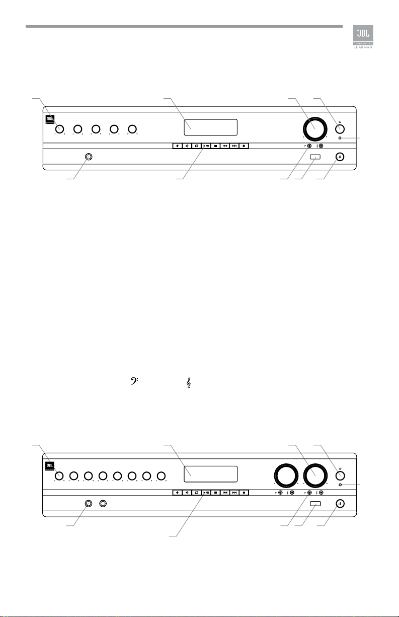
1.2 Front Panel Controls & Indicators
G
A B
1234MUSIC
VMA 160
1
F G
C D
H
MASTER
E
USB
I J
Figure 1.2.1 Front Panel, 1 Channel Model
A. Input Level Controls
B. Media Player Display
C. Output Volume Control(s) Including an Illuminated ring around the output volume
control will light green with signal presence while red indicates clipping, i.e. the
signal has reached the threshold of audible distortion
D. Power Switch
E. Power on LED illuminates blue when power is switched on.
F. Input 1 - Front panel audio input capability via 1/4” TRS connector. The two
channel model includes a second, similar input (Input 4).
G. Media Player Controls
H. Tone Controls - Bass
I. USB Audio Input
J. Bluetooth Key and Indicator
and Treble potentiometers for each output channel.
A B
123 MUSIC 1 4 5 6 MUSIC 2
1
VMA 260
4
F
Figure 1.2.2 Front Panel, 2 Channel Model
C D
H
MASTER 2MASTER 1
E
USB
I J
7

1.3 Rear Panel Controls & Connectors (VMA160, VMA1120, VMA1240)
A B
WARNING
- TO REDUCE THE RISK OF FIRE OR ELECTRICAL SHOCK, DO NOT EXPOSE THIS EQUIPMENT TO RAIN OR MOISTURE.
AVERTISSEMENT
- RISQUE DE CHOC ÉLECTRIQUE - NE PAS OUVRIR.
AVERTISSEMENT
- ÉNERGIE ÉLECTRIQUE DANGEREUSE VOIR LA NOTICE DE FONCTIONNEMENT.
CLASS 2 OUTPUT WIRING PERMITTED
OUTPUTS
100V
70V
COM
CONFORMS TO
UL STD .60065
CERTIFIED TO CSA STD.
C22.2 NO .60065
REMOTE
(CSR-V)
CONTAINS FCC ID: API-MB8811VMA
CONTAINS IC: 6132A-MB8811VMA
CMIIT ID: 2016DJ2941
F
C
CAUTION
RISK OF ELECTRIC SHOCK
DO NOT OPEN
HARMAN INTERNATIONAL
1718 W. Mishawaka Rd.,
Elkhart, IN 46517
Apparatet må tilkoples jordet stikkontakt
Apparaten skall anslutas till jordat uttag
Laite on liitettävä suojakoskettimilla
varustettuun pistorasiaan
CAN-ICES-3(B)/NMB-3(B)
INPUT1
FRONT
PANEL
1-70V/100V Output
2-Chime
3-Input 1 Line/Mic
4-Input 2 Line/Mic
5-Input 2 Phantom
6-Input 3 Line/Mic
7-Input 4 Line/Mic
8-Input 4 Phantom
ONONMIC
MICONMIC
MIC
ON
VOX
(Input 2)
OFF
OFF
OFF
OFF
LINE
LINE
LINE
LINE
G H I
D E
THIS DEVICE COMPLIES WITH PART 15 OF THE FCC RULES. OPERATION IS SUBJECT TO THE FOLLOWING CONDITIONS:
1) THIS DEVICE MAY NOT CAUSE HARMFUL INTERFERENCE, AND
2) THIS DEVICE MUST ACCEPT ANY INTERFERENCE RECEIVED, INCLUDING INTERFERENCE THAT MAY CAUSE
UNDESIRED OPERATION.
PRIORITY
INPUT4
MONO
SUM
MADE IN CHINA
MUSICINPUT2 INPUT3
MONO
SUM
ATTENTION - POUR RÉDUIRE LE
RISQUE DE CHOCK ÉLECTRIQUE, LA
FICHE CENTRALE DE LA PRISE DOIT
ÊTRE BRANCHÉE POUR MAINTENIR
LA MISE À LA TERRE.
CAUTION - TO REDUCE THE RISK OF
ELECTRIC SHOCK, GROUNDING OF
THE CENTER PIN OF THE PLUG MUST
BE MAINTAINED.
100V ~
120V ~
220V-240V ~
50/60Hz 225W
VMA 1240
Figure 1.3.1 Rear Panel - VMA 1240
A. Amplier output connectors.
B. Remote volume connectors – RJ-45 style connector to connect to JBL CSR-V
control module.
C. VOX sensitivity adjustment for Input 1.
D. Input 4 may use either Euroblock or RCA style connector.
E. AC Power Inlet – Detachable IEC.
F. Conguration switches control mic/line gain settings and phantom power for the
inputs as well as enable the chime and 70V/100V output mode.
G. Input 2 – Euroblock connector provides for audio input and priority contacts that
will duck other channels during an announcement when contacts closed using a
switch.
H. Input 3 accepts a 1/4” TRS connector.
I. Music input uses a Dual RCA Connector. Stereo, unbalanced sources will be
summed together.
8

1.4 Rear Panel Controls & Connectors (VMA260 & VMA2120)
INPUT2
1-70V/100V Output
2-Chime
3-Input 1 Line/Mic
4-Input 2 Line/Mic
5-Input 2 Phantom
6-Input 3 Line/Mic
7-Input 3 Phantom
CH1 Settings
8-Not Used
E
MUSIC1 MUSIC2
MADE IN CHINA
INPUT3
MONO
SUM
OFF
ON
OFF
ON
LINE
MIC
LINE
MIC
OFF
ON
LINE
MIC
OFF
ON
NC
NC
MONO
SUM
HARMAN INTERNATIONAL
1718 W. Mishawaka Rd.,
Elkhart, IN 46517
INPUT4
FRONT
PANEL
CH2 VOX
(Input 5)
INPUT5 INPUT6
PRIORITY
1-70V/100V Output
2-Chime
3-Input 4 Line/Mic
4-Input 5 Line/Mic
5-Input 5 Phantom
6-Input 6 Line/Mic
CH2 Settings
7-Input 6 Phantom
8-Not Used
CONFORMS TO
UL STD .60065
CERTIFIED TO CSA STD.
C22.2 NO .60065
M N
100V ~
120V ~
220V-240V ~
MONO
SUM
ATTENTION - POUR RÉDUIRE LE
RISQUE DE CHOCK ÉLECTRIQUE, LA
FICHE CENTRALE DE LA PRISE DOIT
ÊTRE BRANCHÉE POUR MAINTENIR
LA MISE À LA TERRE.
CAUTION - TO REDUCE THE RISK OF
ELECTRIC SHOCK, GROUNDING OF
THE CENTER PIN OF THE PLUG MUST
BE MAINTAINED.
50/60Hz 175W
VMA 260
MONO
SUM
OFF
ON
OFF
ON
LINE
MIC
LINE
MIC
OFF
ON
LINE
MIC
OFF
ON
NC
NC
A B
Apparatet må tilkoples jordet stikkontakt
Apparaten skall anslutas till jordat uttag
Laite on liitettävä suojakoskettimilla
varustettuun pistorasiaan
CH1
CH2
CAUTION
RISK OF ELECTRIC SHOCK
DO NOT OPEN
CAN-ICES-3(B)/NMB-3(B)
OUTPUTS
100V
70V
CLASS 2 OUTPUT WIRING PERMITTED
COM
C D F HG
THIS DEVICE COMPLIES WITH PART 15 OF THE FCC RULES. OPERATION
IS SUBJECT TO THE FOLLOWING CONDITIONS:
1) THIS DEVICE MAY NOT CAUSE HARMFUL INTERFERENCE, AND
2) THIS DEVICE MUST ACCEPT ANY INTERFERENCE RECEIVED,
INCLUDING INTERFERENCE THAT MAY CAUSE UNDESIRED OPERATION.
WARNING
- TO REDUCE
THE RISK OF FIRE OR
ELECTRICAL SHOCK, DO NOT
EXPOSE THIS EQUIPMENT TO
RAIN OR MOISTURE.
AVERTISSEMENT
RISQUE DE CHOC
ÉLECTRIQUE - NE PAS
OUVRIR.
AVERTISSEMENT
ÉNERGIE ÉLECTRIQUE
DANGEREUSE VOIR LA
NOTICE DE
FONCTIONNEMENT.
INPUT1
FRONT
PANEL
REMOTE (CSR-V)
CH2
CH1
1-Input 1 to CH2
2-Input 2 to CH2
3-Input 3 to CH2
4-Music 1 to CH2
5-BT/USB to CH2
6-Input 4 to CH1
7-Input 5 to CH1
8-Input 6 to CH1
Signal Routing
9-Music 2 to CH1
10-Not Used
I K L
PRIORITY
CH1 VOX
(Input 2)
CONTAINS FCC ID: API-MB8811VMA
CONTAINS IC: 6132A-MB8811VMA
CMIIT ID: 2016DJ2940
OFFON
J
Figure 1.4.1 Rear Panel - VMA 260
A. Amplier output connectors.
B. Remote volume connectors – RJ-45 style connector to connect to JBL CSR-V
control modules.
C. Input 2 – Input audio through either the Euroblock connector or the 1/4” TRS
connector. Pins 4 and 5 of the Euroblock are priority contacts that will duck other
channels during an announcement when the contacts are closed using a switch.
D. Input 3 accepts input through either the 3-pin Euroblock or the Dual RCA jacks.
Stereo, unbalanced sources will be summed into a mono signal.
E. Music1 input uses a Dual RCA Connector. Stereo, unbalanced sources will be
summed together.
F. Input 5 – Input audio through either the Euroblock connector or the 1/4” TRS
connector. Pins 4 and 5 of the Euroblock are priority contacts that will duck other
channels during an announcement when the contacts are closed using a switch.
G. Input 6 accepts input through either the 3-pin Euroblock or the Dual RCA jacks.
Stereo, unbalanced sources will be summed together.
H. Music2 input uses a Dual RCA Connector. Stereo, unbalanced sources will be
summed together.
I. Signal Routing DIP switch is used to route inputs to both output channels. By
default, each group of inputs is routed only to its respective output channel (Input
1 – Music1 are routed to output CH1, Input 4 – Music2 are routed to output CH2).
J. VOX sensitivity adjustment for Input 1.
K. CH1 Settings DIP switch is used to enable the 70V/100V output option, turn on
the chime feature, select input gain, and enable phantom power for CH1.
L. VOX sensitivity adjustment for Input 4.
M. CH2 Settings DIP switch is used to enable the 70V/100V output option, turn on
the chime feature, select input gain, and enable phantom power for CH2.
N. AC Power Inlet – Detachable IEC.
9

2.0 Setup
2.1 Unpacking Your Amplier
Please unpack and inspect your amplier for any damage that may have occurred
during transit. If damage is found, notify the transportation company immediately.
Only you can initiate a claim for shipping damage. We will be happy to help
as needed. Save the shipping carton as evidence of damage for the shipper’s
inspection.
We also recommend that you save all packing materials so you will have them if you
ever need to transport the unit. Never ship the unit without the factory pack.
WARNING: Before you start to set up your amplier, make sure you read and
observe the Important Safety Instructions found at the beginning of this manual.
2.2 Installing Your Amplier
CAUTION: Before you begin, make sure your amplier is disconnected from the
power source and all level controls turned completely down (counterclockwise).
Note: We recommend that any sensitive equipment be located at least 8 inches (20
cm) away from the amplier.
To install the amplier, you can use one of the following approaches:
• Rack mount the amplier with the rack mounting kit, see Figure 2.2.2.
• Place a single amplier on a surface with 12 inches of air space around
the unit for convection cooling. Rubber feet are included and can be
attached onto the underside of the chassis. For amplier dimensions,
see Figure 2.2.1.
10

88.10 mm
[3.47 in]
FRONT VIEW
1 2 3 MUSIC 1 4 5 6 MUSIC 2
1
VMA 260
4
SIDE VIEW
432.00 mm
[17.00 in]
401.00 mm
[15.79 in]
Figure 2.2.1 Dimensions
MASTER 2MASTER 1
USB
Front Angle Brackets
Figure 2.2.2 Mounting Kit
Rear Angle Brackets
Rear Flat Brackets
11

Figure 2.2.3 Rack Mounting the Mixer-Amplifier
To install, refer to Figure 2.2.3 and follow the steps below:
1. Attach the front angle brackets to each side of the front of the amplier using the
screws provided.
2. Attach the rear at brackets to each side of the rear of the amplier with the
screws provided.
3. Install the unit into the cabinet using the rack mount screws through the front
angle brackets. For details of installation in the chassis of the cabinet, refer to
the user guide of your cabinet.
4. Align the rear angle brackets with the proper holes at the rear of the cabinet and
attach using rack mount screws.
5. With the rear angle brackets to the outside of the at brackets, attach them each
using a screw passing through two washers, the rear at bracket and the rear
angle bracket as shown in the gure.
12
2.3 Ensuring Proper Cooling
When using an equipment rack, keep a minimum space of 4 inches (10 cm) from
the top surface of the unit. Close any open spaces in the rack with blank panels. DO
NOT block any air vents. The side walls of the rack should be a minimum of 2 inches
(5 cm) from the amplier sides. The back of the rack should be open.
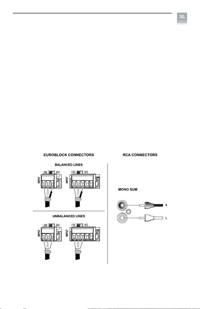
2.4 Choosing Input Wire & Connectors
We recommend using pre-built or professionally wired balanced line (two-conductor
plus shield) 22-24 gauge cables to connect the amplier balanced input by using the
included Euroblock connectors, see Figure 2.4.1. Unbalanced lines may be used,
but may result in hum or RF noise if using very long cable runs.
You can also use RCA connectors to connect audio devices, for example, CD/DVD
player. However, do not use both Euroblock and RCA audio input connectors on a
single channel at the same time.
NOTE: Custom wiring should only be performed by qualied personnel.
AUDIO
SOURCE
AUDIO
SOURCE
AUDIO
SOURCE
AUDIO
SOURCE
Figure 2.4.1 Input Wiring
NOTE: Two RCA connectors are provided for summing left and right channels from a
stereo source. Do not use both Euroblock and RCA connectors concurrently for any
single input channel.
13
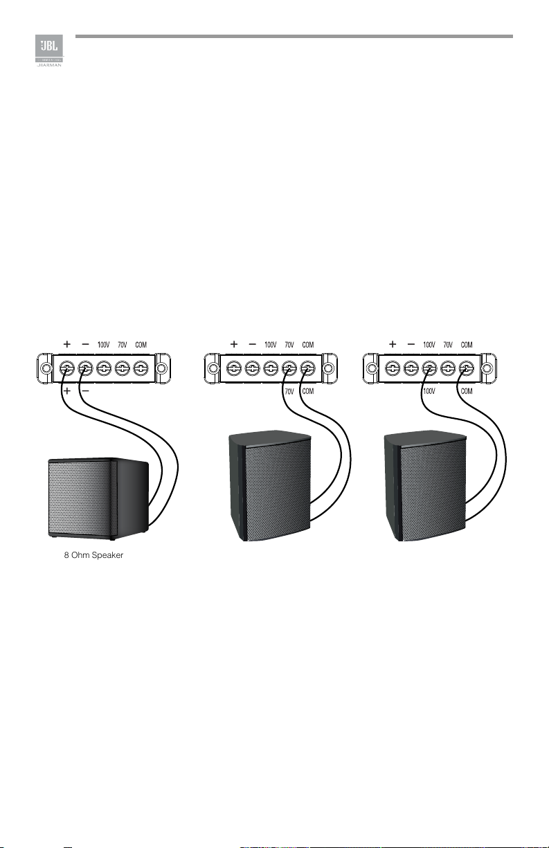
2.5 Output Wiring & Connectors
To drive distributed speaker systems designed to operate at 70V or 100V, connect to
the corresponding output terminals.
JBL recommends using pre-built or professionally wired, high-quality, two-conductor,
heavy gauge speaker wire. Speaker wires should be twisted cable, if possible. To
prevent the possibility of short-circuits, the wires should be stripped back no greater
than 6 mm (1/4 inch), see Figure 2.5.1.
Suggested below are guidelines to select the appropriate size of wire based on the
distance from amplier to speaker. Check with local code as this may vary.
Distance Wire Size
Up to 25 ft. (7.6m) 16AWG
26-40 ft. (7.9-12.2m) 14AWG
8 Ohm Speaker 100V Speaker System70V Speaker System
Figure 2.5.1 Output Wiring
14

2.6 Wiring Your Audio System
WARNING
- TO REDUCE THE RISK OF FIRE OR ELECTRICAL SHOCK, DO NOT EXPOSE THIS EQUIPMENT TO RAIN OR MOISTURE.
AVERTISSEMENT
- RISQUE DE CHOC ÉLECTRIQUE - NE PAS OUVRIR.
AVERTISSEMENT
- ÉNERGIE ÉLECTRIQUE DANGEREUSE VOIR LA NOTICE DE FONCTIONNEMENT.
CLASS 2 OUTPUT WIRING PERMITTED
OUTPUTS
100V
70V
COM
CONFORMS TO
UL STD .60065
CERTIFIED TO CSA STD.
C22.2 NO .60065
REMOTE
(CSR-V)
CONTAINS FCC ID: API-MB8811VMA
CONTAINS IC: 6132A-MB8811VMA
CMIIT ID: 2016DJ2941
LEVEL
CSR-V
CAUTION
RISK OF ELECTRIC SHOCK
DO NOT OPEN
CAN-ICES-3(B)/NMB-3(B)
HARMAN INTERNATIONAL
1718 W. Mishawaka Rd.,
Elkhart, IN 46517
1-70V/100V Output
2-Chime
3-Input 1 Line/Mic
ONONMIC
OFF
OFF
LINE
4-Input 2 Line/Mic
5-Input 2 Phantom
MICONMIC
OFF
LINE
6-Input 3 Line/Mic
LINE
7-Input 4 Line/Mic
8-Input 4 Phantom
MIC
ON
OFF
LINE
Apparatet må tilkoples jordet stikkontakt
Apparaten skall anslutas till jordat uttag
Laite on liitettävä suojakoskettimilla
varustettuun pistorasiaan
THIS DEVICE COMPLIES WITH PART 15 OF THE FCC RULES. OPERATION IS SUBJECT TO THE FOLLOWING CONDITIONS:
1) THIS DEVICE MAY NOT CAUSE HARMFUL INTERFERENCE, AND
2) THIS DEVICE MUST ACCEPT ANY INTERFERENCE RECEIVED, INCLUDING INTERFERENCE THAT MAY CAUSE
UNDESIRED OPERATION.
INPUT1
FRONT
PANEL
VOX
(Input 2)
PRIORITY
CD /OPTICAL
SPK 1 + 2 VIRTUAL
INPUT4
MADE IN CHINA
MUSICINPUT2 INPUT3
RISQUE DE CHOCK ÉLECTRIQUE, LA
FICHE CENTRALE DE LA PRISE DOIT
ÊTRE BRANCHÉE POUR MAINTENIR
CAUTION - TO REDUCE THE RISK OF
ELECTRIC SHOCK, GROUNDING OF
THE CENTER PIN OF THE PLUG MUST
MONO
MONO
SUM
SUM
ATTENTION - POUR RÉDUIRE LE
LA MISE À LA TERRE.
BE MAINTAINED.
100V ~
120V ~
220V-240V ~
50/60Hz 225W
VMA 1240
Figure 2.6.1 Wiring Audio System
Typical input and output connections are shown in Figure 2.6.1.
INPUTS: Connect input wiring for both channels using either the RCA or the
Euroblock input for each channel.
OUTPUTS: You may use either low impedance or high impedance speakers. Always
be sure to maintain the proper polarity when wiring speakers.
Low Impedance Speakers should be driven using the +/- pins of the amplier output
connector. The minimum impedance an amplier channel can drive is 4 Ohms.
Therefore, you can connect up to four 16 Ohm speakers, two 8 Ohm speakers or one
4 Ohm speaker to an amplier output channel.
High Impedance Speakers should be driven using the appropriate (70V or 100V) pin
to speaker (+) and the COM pin to speaker (-) of the amplier output connector. The
minimum impedance that can be driven from each output is provided in Appendix
A. Note that the HI-Z switch must be ON in order to provide audio to the high
impedance outputs.
WARNING: Do not connect to both low impedance speakers and high impedance
speakers from the same audio output channel.
15

2.7 Connecting to AC Mains
Connect your amplier to the AC mains power source (power outlet) with the
supplied AC power cord. First, connect the IEC end of the cord set to the IEC
connector on the amplier; then, plug the other end of the cord set to the AC mains.
When properly connected to a live power source, the power LED should illuminate
blue.
WARNING: The third prong of this connector (ground) is an important safety feature.
Do not attempt to disable this ground connection by using an adapter or other
methods.
Ampliers don’t create energy. The AC mains voltage and current must be sufcient
to deliver the power you expect. You must operate your amplier from an AC mains
power source with not more than a 10% variation above or below the specied line
voltage and within the specied frequency range indicated on the back panel of the
amplier. If you are unsure of the output voltage of your AC mains, please consult
your electrician.
2.8 Protecting Your Speakers
It’s wise to avoid clipping the amplier signal. Not only does clipping sound bad, but
it can damage high-frequency drivers. The built-in clip limiter prevents clipping.
Also, avoid sending strong subsonic signals to the amplier. High-level, low-
frequency signals from breath pops or dropped microphones can blow out drivers.
You can switch to the HI-Z mode which, in addition to switching in the output
transformers for 70V and 100V speakers, activates the high-pass lter. The lter
prevents potentially damaging subsonic signals from going to the amplier by
eliminating signals below 70Hz.
2.9 Startup Procedure
Use the following procedure when rst turning on your amplier:
1. Turn down the level of your audio source.
2. Turn down the level controls of the amplier.
3. Power up the amplier. The blue Power LED should be ON.
4. Turn up the level of your audio source to an optimum level.
5. Turn up the Level controls on the amplier until the desired loudness or power
level is achieved.
If you ever need to make any wiring or installation changes, don’t forget to
disconnect the power cord.
16

3.0 Operation
3.1 Precautions
Your amplier is protected from internal and external faults, but you should still take
the following precautions for optimum performance and safety:
1. Before use, your amplier rst must be congured for proper operation,
including input and output wiring hookup. Improper wiring can result in serious
operating difculties.
For information on wiring and conguration, please consult the Setup section of
this manual.
2. Use care when making connections, selecting signal sources and controlling the
output level.
3. Always be sure to have all levels at minimum when connecting or disconnecting
audio sources from the inputs, especially when MIC is selected from the MIC/
LINE switch. Failure to do so may cause the amplier or speaker to go into a
protection mode or even cause damage.
4. WARNING: Never connect the output to a power supply, battery or power main.
Electrical shock may result.
5. Tampering with the circuitry, or making unauthorized circuit changes may be
hazardous and invalidates all agency listings.
6. Do not operate the amplier with the red Clip LEDs constantly ashing.
7. Do not overdrive the mixer, which will cause clipped signal to be sent to
the amplier. Such signals will be reproduced with extreme accuracy, and
loudspeaker damage may result.
8. Do not operate the amplier with less than the rated load impedance. Due to
the amplier’s output protection, such a conguration may result in premature
clipping and speaker damage.
9. Use the amplier in a well-ventilated environment and do not use it in ambient
temperature conditions in excess of 40°C. Failure to do so will result in the
automatic disconnection from the power supply as the overheat auto protection
function will be activated and there will not be any audio signal coming out
of the amplier. In this case, turn down the volume to the minimum, and the
amplier will soon resume working. When the amplier returns to normal
temperature you may turn the volume up to a safe level.
10. If the line voltage to the amplier is too low, the low voltage protection function
will be activated.
CAUTION: JBL is not liable for damage that results from overdriving other
system components.
17

3.2 Input Routing
CH1 Settings
MIC
MIC
MIC
The two-channel models, VMA260 and VMA2120,
include a default routing of Input channels 1-3, Music
1 and the Bluetooth/USB source to amplier 1. Input
channels 4-6 and Music 2 are routed to amplier 2.
The user may take any input and have it routed to
both outputs by selecting the appropriate switch. For
example, if you set switch 1 to ON, Input 1 will be
routed to both AMP1 and AMP2.
3.3 Conguration Settings
A DIP switch is available for each output channel to congure the unit to your
specic system.
3.3.1 70V/100V Output Selection
When this switch is in the “OFF” position, the amplier is congured to drive low
impedance speakers, (4 Ohms ,minimum) The 70V/100V switch will activate the builtin output transformer allowing the unit to directly drive 70V or 100V speaker systems
when connected to the appropriate output terminals. As an added feature when
driving the high impedance speakers, the system automatically apply a 70Hz high
pass lter.
3.3.2 Chime Function
Turning chime ON will enable a chime sound
at the onset of an announcement when priority
muting is invoked. (See section 3.5, Priority
Muting, on the following page.)
1-70V/100V Output
2-Chime
3-Input 1 Line/Mic
4-Input 2 Line/Mic
5-Input 2 Phantom
6-Input 3 Line/Mic
7-Input 3 Phantom
8-Not Used
3.3.3 Line/Mic Gain Switch
Additional gain is available for use with sources,
in particular microphones, that have low output levels. Switching to MIC position
activates 48dB additional gain. Use only when necessary as the added gain may
cause higher noise levels.
3.3.4 Phantom Power
Phantom power (27V) can be applied to specic mic inputs by turning on the
appropriate Phantom Power switch.
18
OFF
OFF
LINE
LINE
OFF
LINE
OFF
ON
ON
ON
NC
ON
NC

3.4 VOX Function
Voice activated ducking is available on input channel 2 of the VMA160, VMA1120
and VMA1240. The feature is available for both input channels 2 and 5 of the
VMA260, and VMA2120. The audio input level required to activate ducking is set
using the trim pot on the rear panel. Adjusting in the counterclockwise direction will
reduce that level while the full clockwise setting will disable the VOX function.
3.5 Priority Muting
VMA160, VMA1120 and VMA1240 may use Input channel 2 as a priority channel,
muting all other channels when pins 4 and 5 are shorted using a switch closure.
The VMA260, and VMA2120 lets Input2 operate with priority over all inputs into
output amplier CH1. Similarly, Input5 can exercise priority over all inputs into output
amplier CH2. Input2 will have priority over both ampliers CH1 and CH2 if the
routing DIP switch #2 is set to ON.
3.6 Remote Volume Control
Remote volume control can be implemented using a CSR-V controller connected via
an Ethernet cable to the RJ45 connector on the back panel. For the VMA260 and
VMA2120, there are two connectors, one for each amplier output.
19

3.7 Media Player
3.7.1 Bluetooth Operation
To activate Bluetooth, perform the following:
1. Press the Bluetooth Key until the Bluetooth Indicator begins to ash.
2. Enable Bluetooth of your source media player and search for “JBL
COMMERCIAL (XX)”. Establish a connection. (Note that the “XX” represents
the last two digits of the MAC address which allows the user to have multiple
systems in close proximity.)
3. Once connected, the Bluetooth Indicator will stop ashing and remain
illuminated.
4. Press the VOLUME UP/VOLUME DOWN keys to increase or decrease the
volume.
5. Press the NEXT key to jump to the beginning of the next track.
6. Press the PREVIOUS key once to jump to the beginning of the current track or
twice to the previous track.
7. Press the STOP key to stop playing. (Note: This may not work for some
Bluetooth devices.)
8. Press the PLAY/PAUSE key to pause or resume playing.
9. To disconnect, either press the Bluetooth Key or disable Bluetooth at the media
player source device. (Note: Play will resume automatically upon reconnect if
disconnected by pressing the Bluetooth Key.)
10. Press the REC key to start recording. (Note: Media player signals are not
recorded.)
Note: Bluetooth signal is muted when broadcasting the chime tone.
3.7.2 USB Operation
1. Insert a USB Drive to the USB Audio Input and the number of folders and les on
the USB Drive will be displayed.
2. Press PREVIOUS or NEXT Key to scroll the playable media.
3. Press the VOLUME UP/VOLUME DOWN keys to increase or decrease the
volume.
4. Press the REPEAT Key to enter different repeat modes:
• REPEAT CURRENT – Repeat the current track.
• REPEAT ALL – Repeat all tracks.
• REPEAT ALL 30Min Message – Play the track with the predened name,
“MESSAGE_1.mp3” every 30 minutes while repeating all other tracks.
20

• REPEAT ALL 60Min Message – Play the track with the predened name,
“MESSAGE_1.mp3” every 60 minutes while repeating all other tracks.
• REPEAT OFF – No repeat.
5. Press the PLAY/PAUSE key to pause or resume playing.
6. Press the STOP key to stop playing.
7. Press the PREVIOUS Key once to jump to the beginning of the current track or
twice to the previous track.
8. Hold down the PREVIOUS Key to rewind.
9. Press the NEXT Key to jump to the beginning of the next track.
10. Hold down the NEXT Key to fast forward.
11. Press the REC key to start recording. (Note: Media player signals are not
recorded.)
3.7.3 Additional Media Player Information
Bluetooth playback will always have priority over USB.
The default media player volume is maximum.
USB and Bluetooth signals cannot be recorded.
While playing from the USB or Bluetooth source, the signal being played is
interrupted momentarily when a chime tone is sounding in another channel.
Hidden functions are available by pressing and holding a media player key for more
than 1 second then pressing and holding the Bluetooth key along with it.
• RECORD (>1s) + BT Displays the BT MAC address
• STOP (>1s) + BT Displays the rmware version
• PLAY (>1s) + BT Illuminates all dots in the display
• REPEAT (>1s) + BT Factory Reset
3.7.4 Firmware Upgrade Procedure
1. Place the rmware le “*.mcs” onto a blank USB Drive.
2. Insert the USB Drive.
3. Display will show “USB UPGRADE”.
4. Wait until display shows “USB SUCCESS” and the display turns off.
5. Power off the unit.
6. Remove the USB Drive.
7. Power on the unit, the upgrade procedure is nished.
21

4.0 Troubleshooting
CONDITION: No power to the mixer-amplier so that the power LED is not
illuminated.
POSSIBLE REASON: The mixer-amplier is not plugged into the power outlet.
CONDITION: No sound or low sound.
POSSIBLE REASON: The input signal is not present or at a very low level.
POSSIBLE REASON: The Master Volume control is turned down.
POSSIBLE REASON: A CSR-V is connected and turned down.
POSSIBLE REASON: Mixer channel inputs are turned down.
POSSIBLE REASON: A Priority switch is closed, muting all except the priority input.
POSSIBLE REASON: The 70V/100V switch is OFF while using the 70V or 100V
outputs.
CONDITION: Distorted sound.
POSSIBLE REASON: Input signal level is too high. Please turn down the input level
controls. Note that the mixer-amplier should not be operated at a level that allows
the clip indicator (red ring around the Master Volume) to be constantly ON.
POSSIBLE REASON: Master Volume is too high.
POSSIBLE REASON: MIC/LINE switch is in MIC position when using a line level
source.
22

Appendix A: Target Performance Specications
Performance VMA160 VMA1120 VMA1240 VMA260 VMA2120
Max Output Power per Channel
into 4 Ω or 8 Ω; 1kHz, ≤ 0.5% THD
Insertion Loss
(70V & 100V outputs)
Number of Input Channels
Number of Output Channels
Tone Controls
(Bass and Treble non-detented
potentiometers on each channel)
Input Sensitivity
(to obtain full rated power into 8
Ω load)
Frequency Response
(measured at 2.83V
load impedance at any output)
Total Harmonic Distortion (THD)
(measured at 2.83V
load impedance at any output)
Signal-to-Noise Ratio
(Ref. Rated Power, mixer levels
@ min., master volume @ max.
A-weighted)
Input Impedance
(nominal)
Phantom Power
Crosstalk
(reference rated power, volume at
mid position, 1kHz)
Nominal AC Line Voltages
Minimum Load Impedance
Low Impedance Output
70V Output
100V Output
Operating Temperature/
Humidity
Storage Temperature
Dimensions & Weight
Net Weight
Dimensions
Shipping Weight
into rated
RMS
into rated
RMS
60W 120W 240W 60W 120W
1 dB maximum
5 5 5 8 8
1 1 1 2 2
Bass +/-14dB @ 50Hz
Treble +/-14dB @ 10kHz
4 Ω
80 Ω
160 Ω
19.4 lb
(8.8 kg)
24.6 lb
(11.2 kg)
Mic Input: 5.5mV
Line Input: 1.3V
RCA Input (stereo in): 130mV
4/8 Ω Output: 20Hz - 20kHz, +/-2dB
70V/100V Outputs: 80Hz - 15kHz +/-3dB
Power Amp Output: <0.5%, 20Hz - 20kHz
>76dB
Mic: 400 Ω
Line: 20 kΩ (balanced)
RCA: 50 kΩ
27VDC
-70 dB
100V, 120V, 220V, 220-240V, 50/60 Hz
4 Ω
40 Ω
80 Ω
0°C to 35°C @ 95% R.H. (non-condensing)
20.2 lb
(9.2 kg)
25.5 lb
(11.6 kg)
4 Ω
20 Ω
40 Ω
-20°C to 85°C
25.5 lb
(11.6 kg)
Width: 17.0 in. (432 mm)
Depth: 16.3 in. (415 mm)
Height: 3.5 in. (88 mm)
30.8 lb
(14 kg)
RMS
RMS
RMS
4 Ω
80 Ω
160 Ω
25.5 lb
(11.6 kg)
30.8 lb
(14 kg)
(13.3 kg)
(15.7 kg)
29.3 lb
34.5 lb
4 Ω
40 Ω
80 Ω
Note: For AC power draw and thermal dissipation information, please visit our
website. www.jblcommercialproducts.com
23

Appendix B: Block Diagrams
TO CH2
VMA260 & VMA2120
Input 1 Mic/Line
[1/4" Bal]
Input 2 Mic/Line [Bal]
1/4" Bal
Input 2 PTT
Input 3 Mic/Line [Bal]
Summed RCA
Music 1 Line
[Summed RCA]
BT/USB
+27V
+27V
TO CH2
Control:
- Chime CH2 ON/OFF
- Input 5 PTT
VOX
*CH1_BT_SW*
Input 4 to Ch 1
Input 5 to Ch 1
Input 6 to Ch 1
Music 2 to Ch 1
TO CH2
TO CH2
TO CH2
Attenuation
Input 4
Input 5
Input 6
(VOX/PTT)
CH1_PRIORITY
Music 2
*CH2_CTRL_3*
- Input 1 to Ch 2
*CH2_CTRL_4*
- Input 2 to Ch 2
- CH1_PRIORITY
Input 3 to Ch 2
Music 1 to Ch 2
TO CH1
TO CH1
TO CH1
TO CH1
Input 1
Input 2
Input 3
Music 1
Input 2 to Ch2
*CH2_CTRL_1*
Control:
- Input 1 to Ch 2
- CH1_PRIORITY
- CH2_PRIORITY
Attenuation
(VOX/PTT)
CH2_PRIORITY
Input 4 Mic/Line
[1/4" bal]
Input 5 Mic/Line [Bal]
1/4" Bal
Input 5 PTT
Input 6 Mic/Line [Bal]
Summed RCA
Music 2 Line
[Summed RCA]
BT/USB
+27V
+27V
- Chime CH2 ON/OFF
- BT/USB to CH2
- Input 2 PTT
- Input 5 PTT
VOX
*CH2_BT_SW*
24

VMA260 & VMA2120 Continued
Hi-Z Switch
TONE
CONTROL
HPF
MASTER VOLUME
VCA
REMOTE VOLUME
Feedback
SDRAM
SPICLIP
POWER
AMP
CRYSTAL
OUTPUT
TRANSFORMER
(CH 1)
100V
70V
COMMON
-
+
TONE
CONTROL
Hi-Z Switch
HPF
MASTER VOLUME
REMOTE VOLUME
VCA
Feedback
FLASH
SPICLIP
POWER
AMP
MCU
BT MODULE
DAC
BT/USB
MCU SECTION
100V
OUTPUT
TRANSFORMER
(CH 2)
70V
COMMON
-
+
25

VMA160, VMA1120 & VMA1240
Input 1 Mic/Line
[1/4" Bal]
+27V
Input 2 Mic/Line [Bal]
Input 2 PTT
Input 3 Mic/Line
[1/4" Bal]
Input 4 Mic/Line [Bal]
Summed RCA
Music Line
[Summed RCA]
BT/USB
TONE
CONTROL
Hi-Z Switch
+27V
HPF
MASTER VOLUME
REMOTE VOLUME
VCA
Feedback
VOX
Attenuation
(VOX/PTT)
CH1_PRIORITY
OUTPUT
TRANSFORMER
100V
70V
COMMON
SPI CLIP
POWER
AMP
-
+
CRYSTAL
SDRAM
DAC
MCU
FLASH
BT MODULE
BT/USB
MCU SECTION
26

Appendix C: Contact Information
For additional information, please consult JBL Professional Customer Service, your
system installer or retailer.
On The World Wide Web:
www.jblcommercialproducts.com
Professional Contacts, Outside the USA:
Contact the JBL Professional Distributor in your area. A complete list of JBL
Professional international distributors is provided at our U.S.A. Website: www.jblpro.
com.
27

JBL Commercial
10653 South River Front Parkway,
Suite 300
South Jordan, Utah 84095
Part Number: 5078447-A Issue: 09/16
 Loading...